

Page 1
by FisKerPr ice®
KAWASAKI® NINJA ATV
ASSEMBLY MANUAL
YOUTH SERIES VEHICLE • USE TYPE H BATTERIES ONLY
AA BATTERIES FOR SOUND BOX NOT INCLUDED
FOR WIODELS AO4590/74590-9993
WARNING
A
Children can be harmed by the small parts, sharp edges and sharp points in the unassembled state,
or by electrical items. Care should be taken in unpacking and
assembly of the vehicle. Children should NOT handle parts, batteries, or help in assembly.
Page 2

TOLL-FREE SERVICE LINES
Multi (twenty-five) service lines, open from 8:00 AM to 7:00 PM
Monday through Friday and Saturday, 9:00 AM to 5:00 PM
1-800-348-0751
¿Habla Español? Si usted tiene alguna pregunta ó necesita asistencia
llame gratis 1-800-348-0755 para los Estados Unidos.
A NATIONAL SERVICE CENTER NETWORK
Over 300 service centers
nationwide
Our service centers will repair or
replace parts under warranty at
no charge
ALWAYS CHARGE THE
BATTERIES A FULL
18 HOURS THE FIRST
TIME. AFTER THAT,
RECHARGE FOR
14 HOURS.
THIS VEHICLE USES A POWER
WHEELS® TYPE H BATTERY AND A •
POWER WHEELS TYPE H CHARGER
ONLY NO OTHER TYPE WILL WORK. •
Even with proper care, the rechargeable
battery will not last forever. The replacement •
battery
must be a Type H battery.
Eor vehicles beyond warranty,
our service centers will perform
repairs for a minimal charge
purchase, contact:
Dealer where your vehicle was
purchased.
Power Wheels Customer Service
1-800-348-0751
Authorized Service Center^^^^^^^^^^^^^
(See Authorized Service Center list).
IMPORTANT
in the unlikely event that any of the parts are missing or damaged,
contact customer service 1 “800-348-0751.
Page 3
'V
________________
LOWER HEADLIGHT ROUSING
fim
~ ~T'X
k..
HEADLIGHT GUARD
AND RIM
SOUND BOX
_____
_____________
upper HEADLIGHT HOUSING
MUDFLAP (2)
Page 4

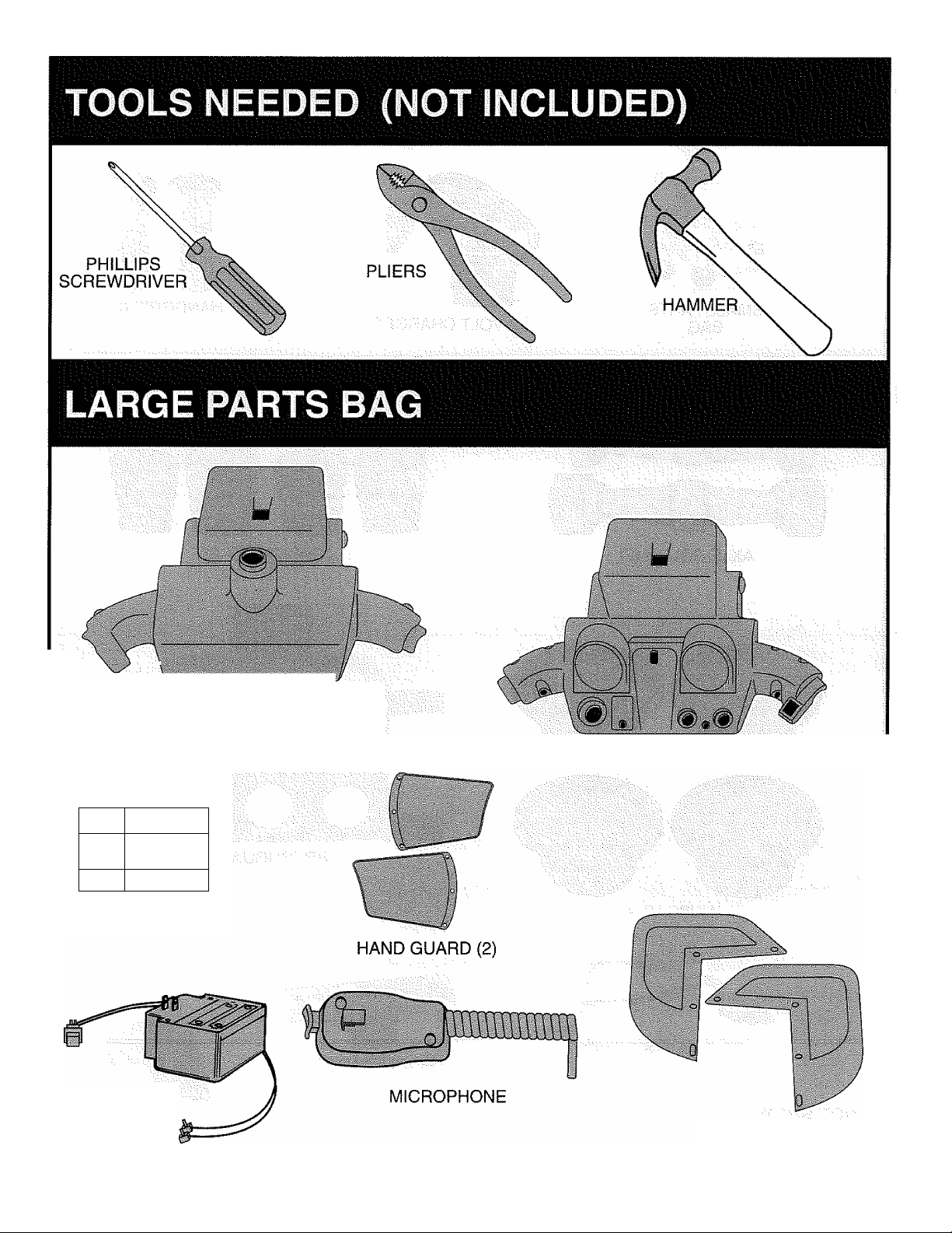
SMALL: PARTS
BAG
AXLE COVER (2) SHOCK SET (2)
12-VOLT CHARGER
HANDGRIP (2)
NOT SHOWN:
LITERATURE BAG
HUBCAP (4)
HANDLEBAR NECK
COVER PLATE
Page 5

Page 6
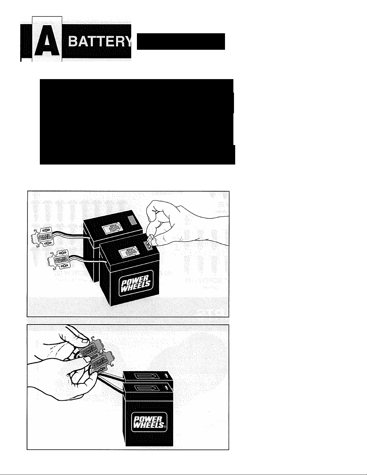
CHARGING
FOLLpW EACH STEP CAREFUL
It is important that you use only Power Wheels®
Type H batteries.
These batteries have the correct plug connectors
and dimensions necessary for proper battery com
partment fit.
For more information on these 6-volt Type H batter
ies, please refer to your Owner’s Manual.
r
ASSEMBLY
BY
ADULTS
' =-||||;||f
DO NOT
OMIT ANY
STEPS
INSERT 30 amp fuses into
batteries.
A
STACK battery connectors.
Page 7

3
YOUR vehicle has the Power
Wheels® Lock-In™
Connectors.
SQUEEZE tabs on charger
and push into battery
connectors to lock in.
(To disconnect, simply
squeeze tabs and puli.)
FIRST TIME
HRS.
A C A U T I O N
Leaving the batteries in a discharged
condition will ruin them. Batteries
must be charged once a month even if
the vehicle is not used. Carefully read
;;the battery care instructions in the v
Owner’s Manual
to obtain the best battery life.
4
PLUG battery charger into
wail outlet,
CRARGE battery for a
minimum of 18 hours for the
first charge. (After that 14
hours is enough.) Power
Wheels recommends not
chargirig over 30 hours.
Page 8

WHEELS
1
TURN VEHICLE UPSIDE
DOWN.
slide two large washers on
rear axle.
SLIDE rear drive wheel onto
rear axle.
ALIGN ribs on driver with
slots on gearbox.
2
PLACE deep hubcap onto
outside of wheel.
3
SLIDE hex bushing onto axle,
through hubcap, into wheel.
8
Page 9

Page 10

3
PLACE hubcap into outside
of wheel.
4
SLIDE hex bushing onto axle,
through hubcap, into wheel.
10
5
HAMMER a large retainer
onto axle.
REPEÁT for other side.
Page 11

ALIGN three holes in
handlebar and neck.
PLACE steering column
through neck and handlebar
for afignrhent.
Note: Pimple should face
away from neck.
PUSH 1J1/2” screw through
each outer hole.
ATTACH lock nut on end of
each screw.
TIGHTEN with screwdriver
and pliers.
2
REMOVE steering column
from handlebar assembly.
SLIDE steering column
through hole #1 in bottom of
steering linkage and through
top of body.
PLACE curved end of
steering column through hole
#2 in top bar of steering
linkage.(lf assembly is difficult,
insert steering column into hole
#2 and curved end into hole #1.)
Page 12

2
OBTAIN upper headlight
housing,
THREAD switch and wire
through hole.
SNAP switch into hole.
ATTACH sound box harness
to sound box.
3
POSITION VEHICLE WITH
ALL FOUR WHEELS ON
FLOpR.
ATTACH cover plate with two
1/2” screws (silver).
TIGHTEN.
12
SLIDE lower headlight
housing on steering column.
SLIDE on neck and
handlebar.
Note: If neck/handlebar does
not fit right, check that
handlebar dimple is on top.
Page 13

HOLD bottom of steering
column.
HAMMER retainer onto top of
steering column.
6
PLACE upper housing over
lower housing (making sure
wire is tucked inside
housing).
ATTACH upper and lower
housing with six 1/2” screws
(black).
13
7
ATTACH rim (with sound box)
to front of upper and lower
handlebar housing with four
1/2” screws (black).^
Page 14

8
REMOVE headlight guard.
APPLY HEADLIGHT
DECAL.
SNAP headlight guard back
into rim.
9
MOISTEN handgrip with
warm water.
SLIDE handgrip onto end of
handlebar.
REPEAT on other side.
14
Page 15

2
INSERT radio dials into holes
in right side of dash.
3
PLACE brushguard around
top of roll-bar.
INSERT 3/4” screw
(two places).
TIGHTEN.
15
4
BEND brushguard around
roll-bar.
INSERT 3/4” screws
(four places).
TIGHTEN.
Page 16

WINDSHIELD/
SNAP windshieici on to front
of handiebar housing
attach hand guard to
windshield with three 1/2”
screws (black).
REPEAT on other side.
Page 17

ATTACH shocks with two 1/2”
screws (black).
REPEAT for other side.
3
PLACE short axle cover
behind axie.
SNAP into place.
PLACE long axle cover to
axle.
SNAP into place.
PROPER DEGAL APPLICATION WILL KEEP THE
DECALS LOOKING THEIR BEST!
WASH your hands before applying decals.
WIPE the vehicle with a soft dry cloth to remove dust.
REMOVE decal from backing sheet.
ALIGN decal in desired position.
L/V^ down one edge of decal/then slowly lay down the
rest of the decal rubbing toward the center as
you go.
After decal is in position,
RUB the decal firmly with the cloth to be sure adhesive
is in firm contact.
17
Page 18

2
PLACE batteries in vehicle v
with connectors facing to the
side of battery compartment.
SQUEEZE tabs on motor
harness and push into battery
connectors to lock in.
3
INSERT ends of battery
retainer into holes in body.
18
Page 19

4
PUSH carriage bolt through
underside of vehicle and
battety retainer.
ATTACH small washer and
wing nut.
TIGHTEN securely.
5
SLIDE tabs on front of seat
into openings at front of
battery compartment.
PRESS rear of seat down
until locking tabs snap into
place on each side.
IMPORTANT:.;::.:,
Carefully read your Owner’s Manual for important
safety messages and operating instructions
before using your vehicle.
REMEMBER
THE FIRST TIME ...
Charge the batteries for a minimum of “18 hours.
AFTER,THAT,;
Charge the batteries a minimum of 14 hours.
HiGH-SPEED CONNECTION
Your vehicle is now ready to go. For safety
reasons, it will only operate in low speeds.
To connect high-speed see Owner’s Manual.
19
OWNER'S MANUAL
KAWASAKr
NINJA ATV
PL£A5E READ THIS MANUAL AND KEEP IT
This moriucd contaim irT^x>rtQnt ^formaJlon
: • Ploase t« sure .to sove your iocorpt, •;;
: IF YOU HAVE OU£$TtONS OR NEED ASiST^CS;
^ Engllth Of $poni(h.
MMMEMCCt C
FOR FUTURE REFERENCE
•ihot you y/i5l nood to rof Gfertce.
T1£ASECAliTOU‘l^li
POMR SVHEEL5 CUSTOMER S^CI
Custonsei SeMce RopiAMrutolN«»
om to take your cQlt in
i-eoO'Me'075i
E»ta manual tombldn
dtsponlble on ospalSol.
Page 20

WHEEtS
by Fisher^Price®
KAWASAKI®
NINJA ATV
FOR MODELS AO4590 / 74590-9993
Power Wheels
Fort Wayne, Indiana
©KAWASAKI IS A LICENSED TRADEMARKS OF KAWASAKI MOTOR CORP.
©1994 FISHER PRICE, INC. - ALL RIGHTS RESERVED
U.S. PATENTS 4,555,451; 4,558,263; DES 327,512; 5,051,550; AND U.S. PATENTS PENDING
CAUTION \ Electric vehicle not recommended for children under 3 years of age.
As with all electrical products, precautions should be observed during handling and use to
prevent electrical shock.
CHARGER: TYPE H INPUT: 120 VAC 60 HZ 28W
OUTPUT: 12VDC 1200 MA
P/N 80037-0259
 Loading...