How it Works
Log In / Sign Up
Buy Points
How it Works
FAQ
Contact Us
Questions and Suggestions
Users
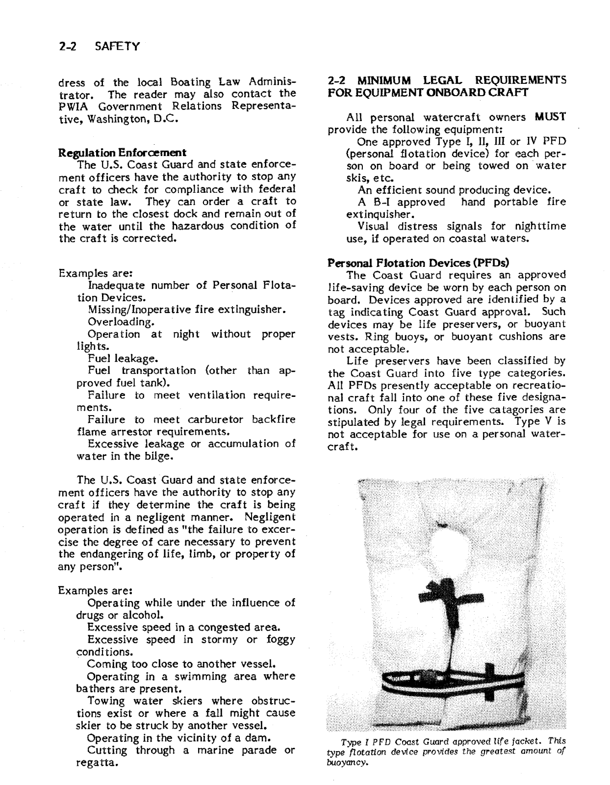
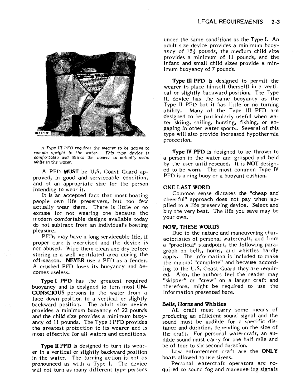
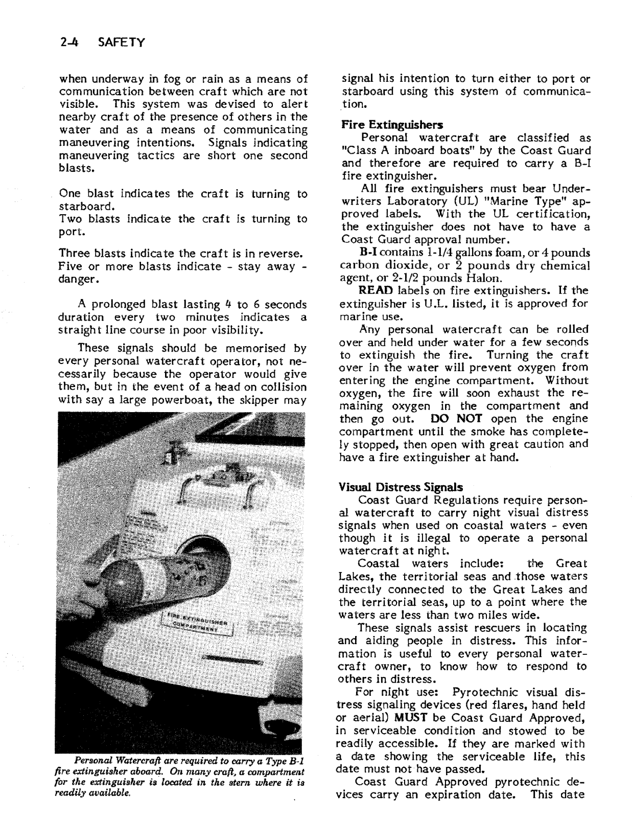
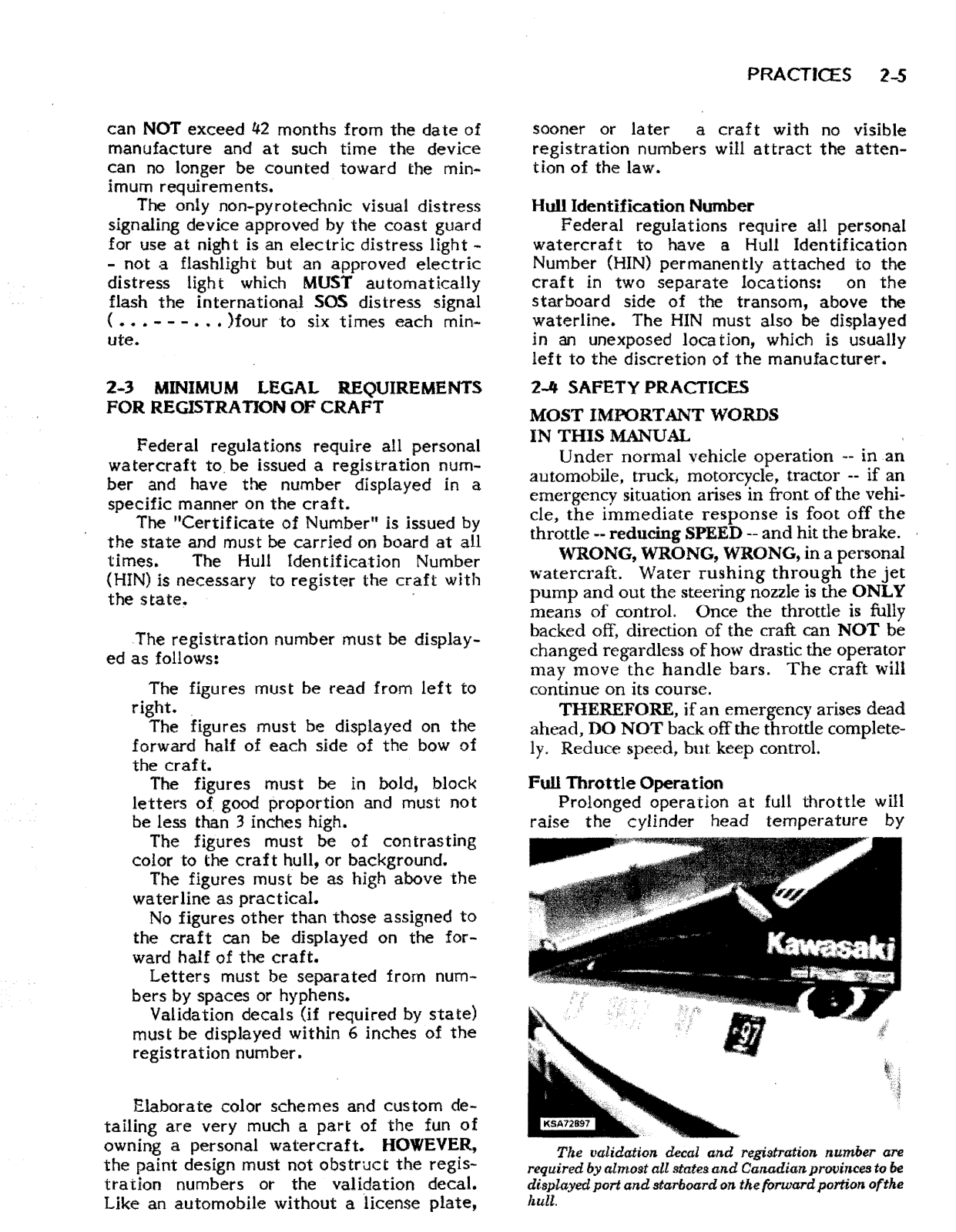
Kawasaki
Loading...
#
90 G3SS
90 GA1-A
90 GA2-A
900
900 CLASSIC
900 CLASSIC - BROCHURE 2010
900 CLASSIC LT
900 CLASSIC LT - BROCHURE 2010
900 CUSTOM
900 CUSTOM - BROCHURE 2010
900Z1-A 1974
840109
840116
840121
840128
840131
840135
2
840138
840139
840150
840168
840169
2
840184
840194
840223
840225
840271
840272
840273
840276
840327
840328
840329
840330
840378
840441
840442
840443
840444
840457
840458
840460
840475
840517
840557
2
840563
840589
840595
840638
840639
2
840641
840644
840646
840700
840844
843327
840131-1HR
840138-1HR
99994-1299
A
A1 1970
A1 1971
a2
A7 1970
A7 1971
AO4590
ASTRO SA340-A1
ASTRO SA440-A1
B
Band Saw
BAYOU 250
3
BAYOU 250 (2003)
Bayou 300
Bayou 300 1999
BF650 4X4
BF650 4X4 - BROCHURE 2010
BF650 4X4I
BF650 4X4I - BROCHURE 2009
BF650 4X4I - BROCHURE 2010
BF750 4X4I
2
BF750 4X4I - BROCHURE 2009
BF750 4X4I - BROCHURE 2010
BRUTE FORCE 300
BRUTE FORCE 650
Brute Force 650 4x4
2
BRUTE FORCE 750
2
BRUTE FORCE 750 2008
BRUTE FORCE 750 4×4i
2
BRUTE FORCE 750 4×4iEPS
Brute Force 750 4x4i
6
BRUTE FORCE 750 4x4iEPS
2
C
C7478
CD1677
COMPONENT #690551-1HR
Concours 1000GTR
CONCOURS 14
6
CONCOURS 14 ABS
5
Concours 14 ABS 2013
CONCOURS 14 ABS 2014
Contours 1000GTR
D
D-TRACKER
D-TRACKER 125
10
Loading...
Loading...
Nothing found
900
Service Manual
245 pgs
46.87 Mb
0
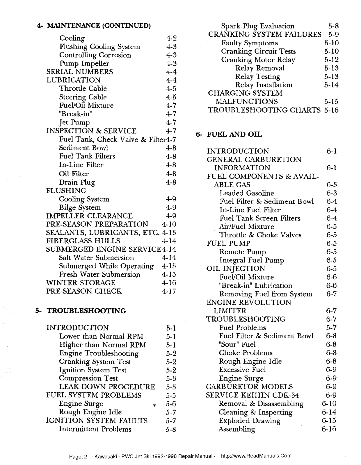
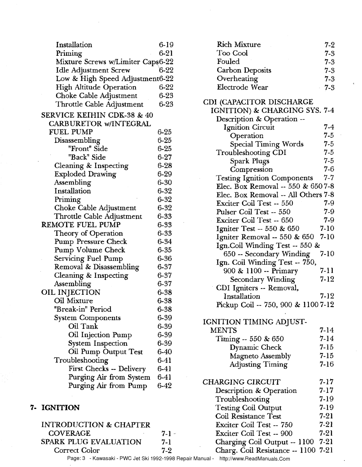
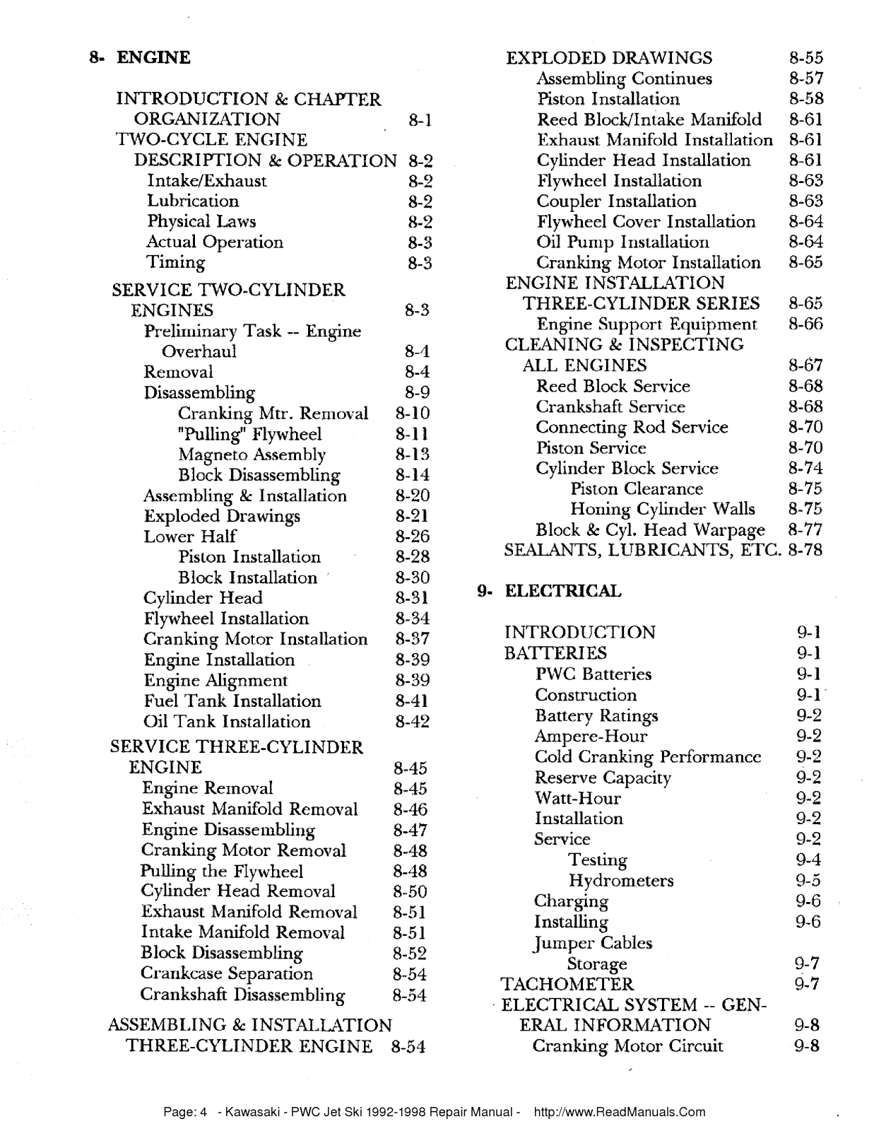
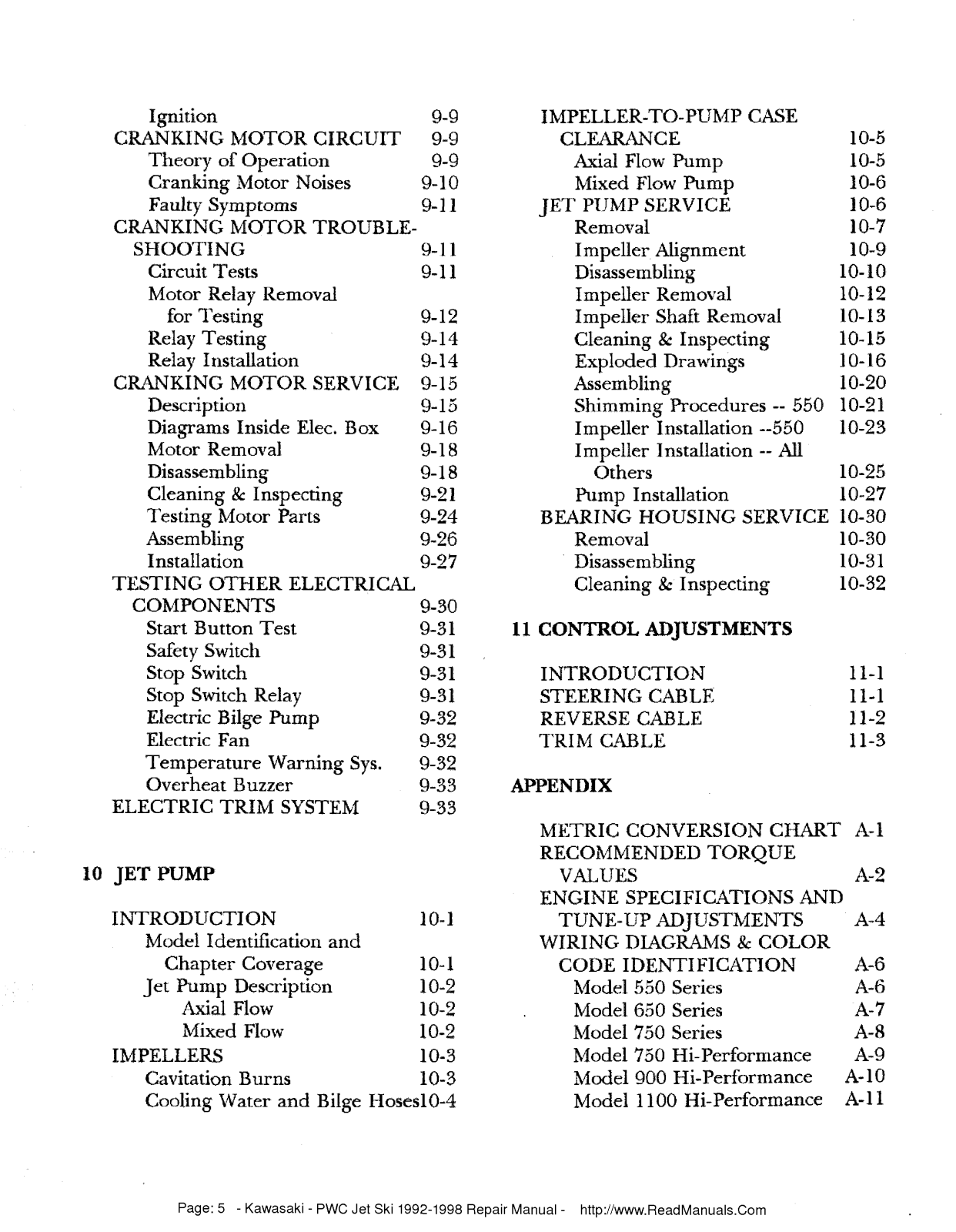
Table of contents
Loading...
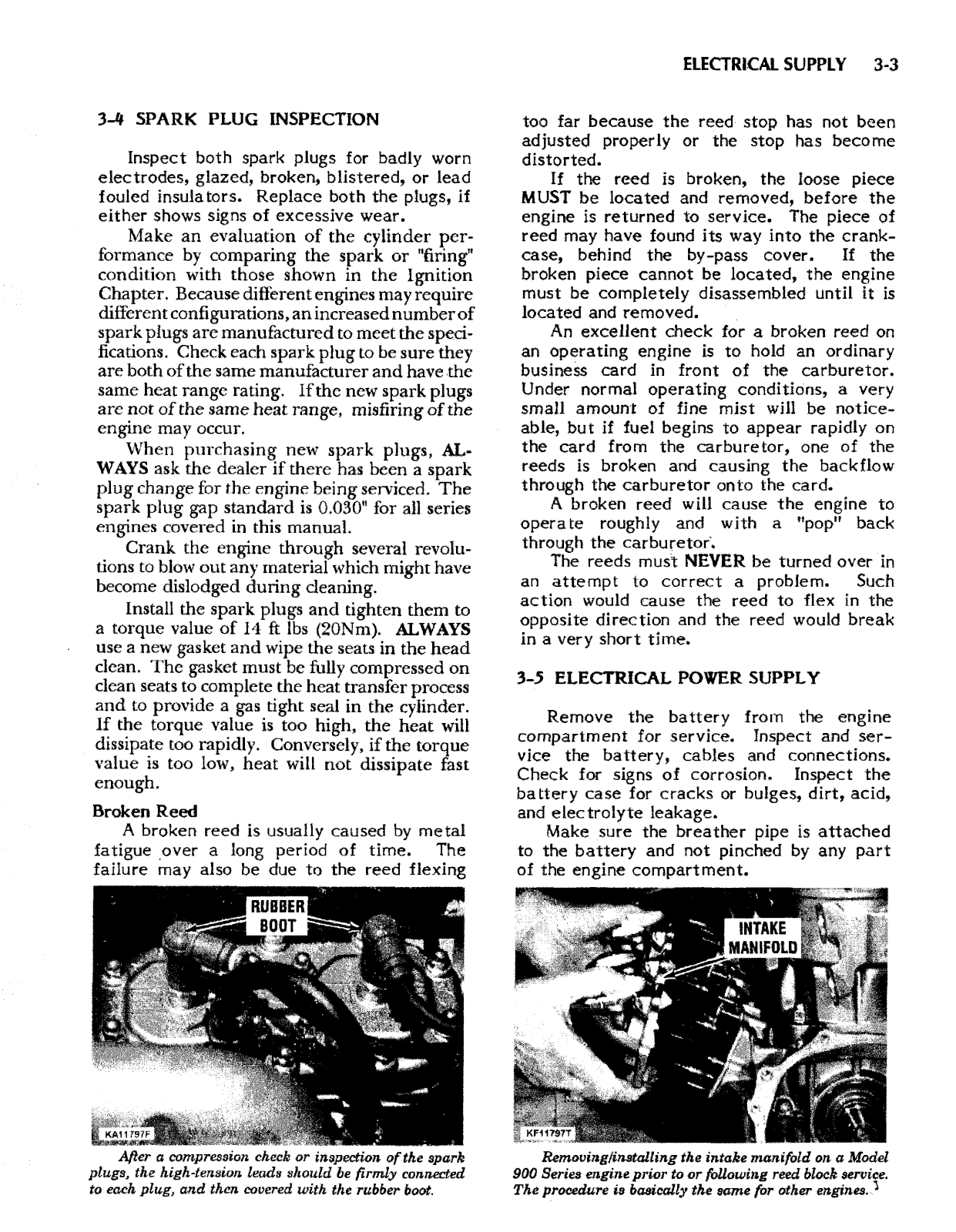
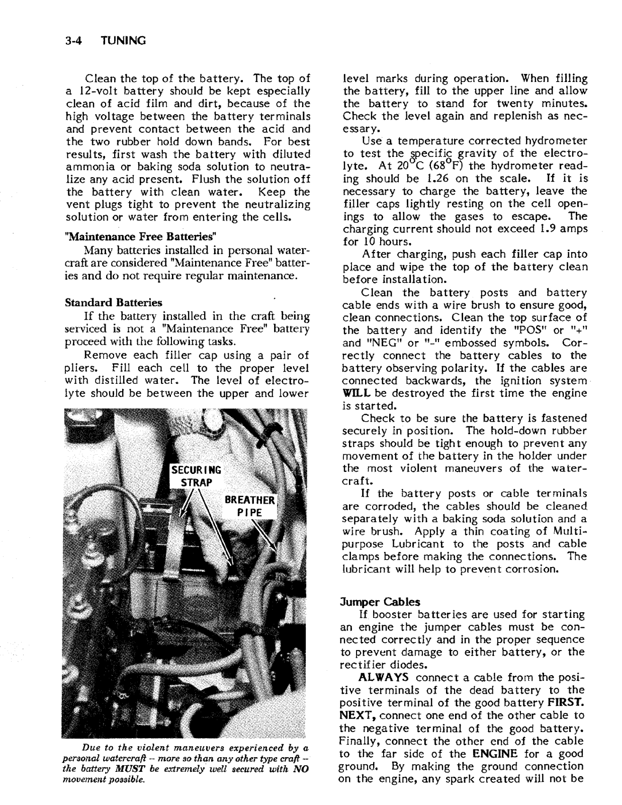
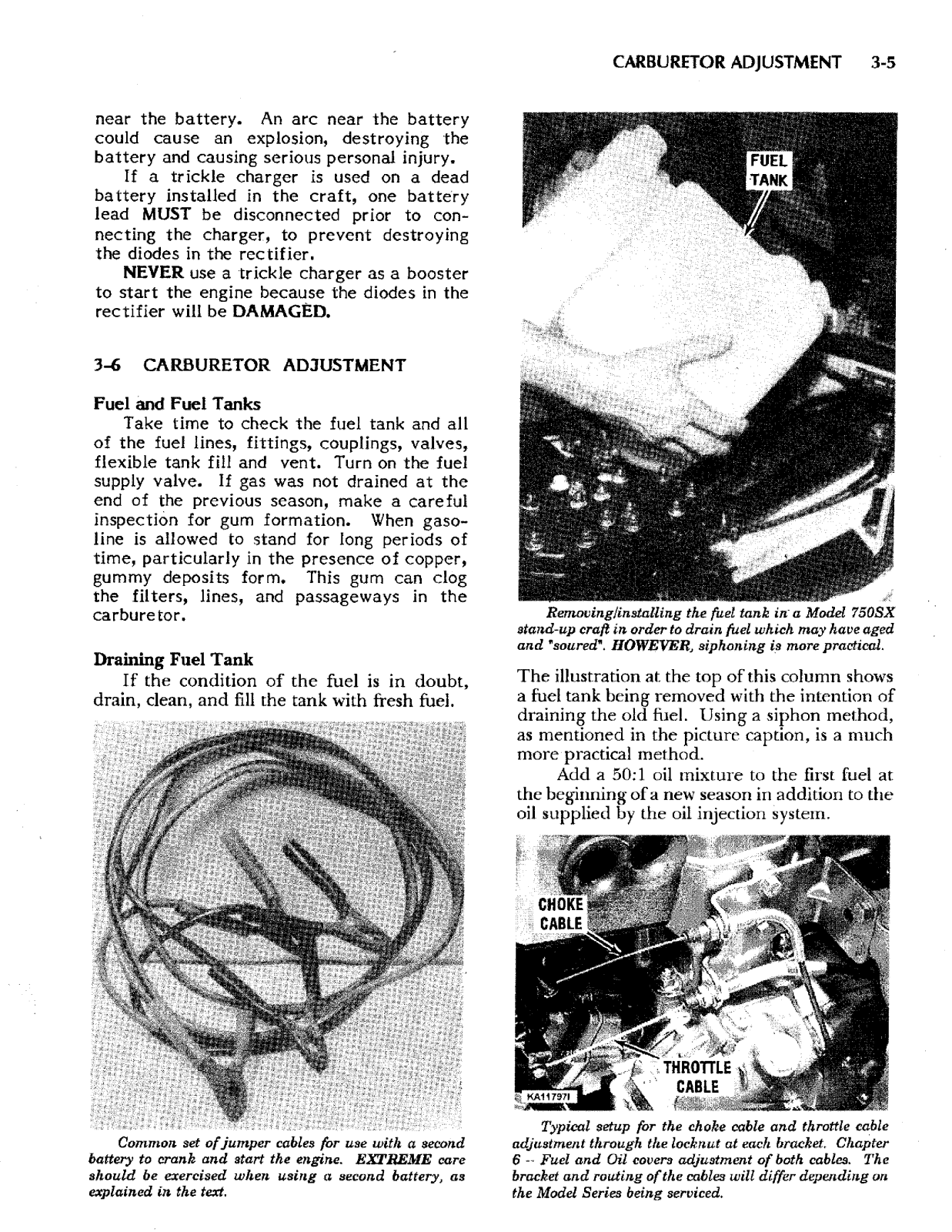
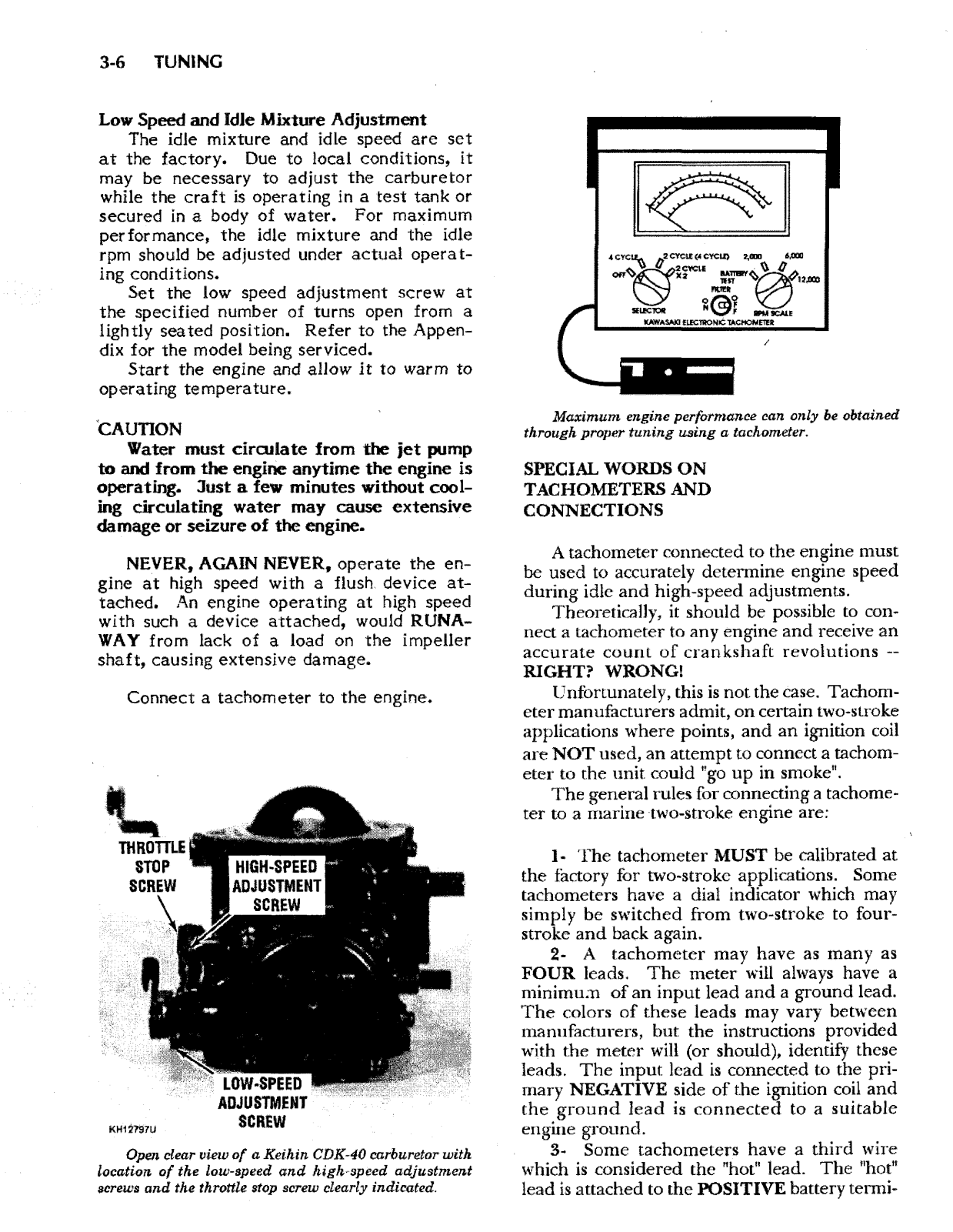
Kawasaki 900 Service Manual
...
Kawasaki Service Manual
Download
Specifications and Main Features
Frequently Asked Questions
User Manual
Download
Loading...
+
215
hidden pages
Unhide
You need points to download manuals.
1 point = 1 manual.
You can buy points or you can get point for every manual you upload.
Buy points
Upload your manuals
 Loading...