

Page 1

Service Manual
– GP –
HYBRID PIANO
Manufacturing Start Date 2014/05
KAWAI MUSICAL INSTRUMENTS
MANUFACTURING CO.,LTD.
KPSZ-0804
Date of issue : July 2015
Copyright © 2015 Kawai Musical Instruments Mfg. Co., Ltd. All rights reserved.
Page 2

– 2 –
■CONTENTS
SPECIFICATION 3
〔1〕INFORMATION 4
〔2〕BASICSTRUCTURE 4
【A】OperationofMuteMechanism 4
【B】OverviewofHammerSensor 5
〔3〕ADJUSTMENTS 6
【A】ExtractionofActionUnit 6
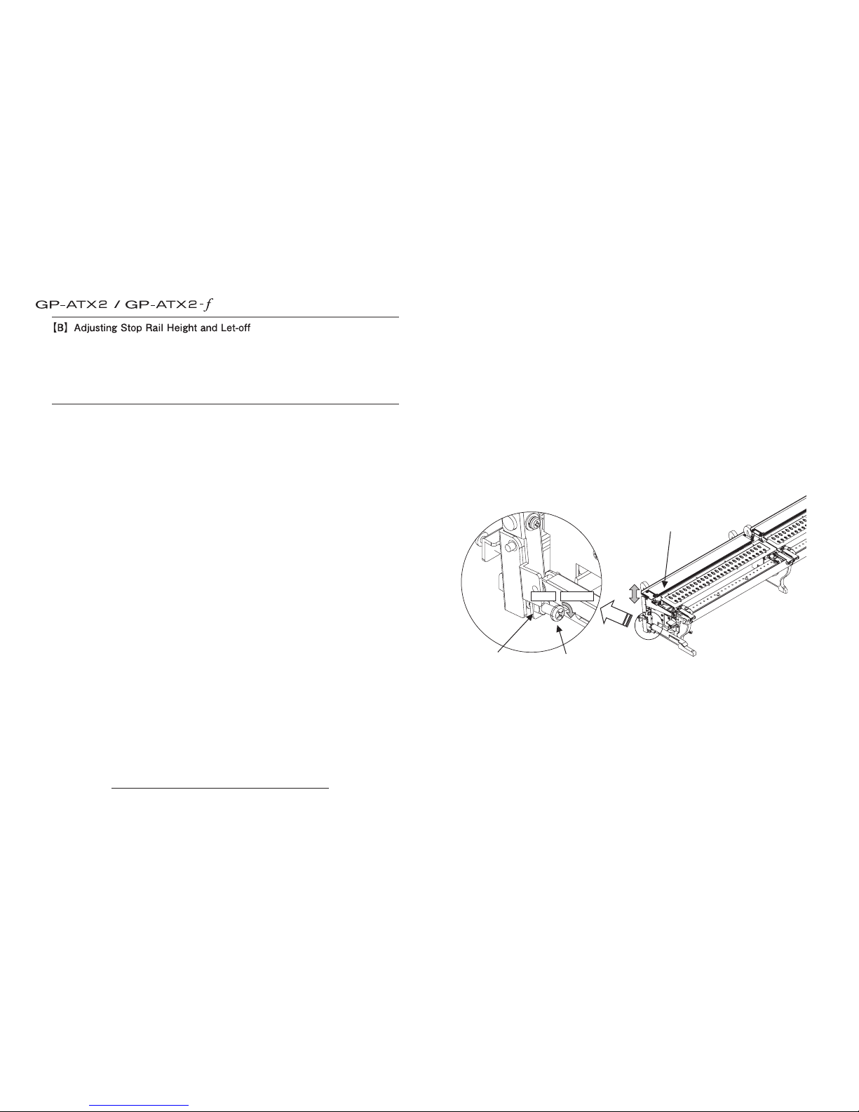
【B】AdjustingStopRailHeightandLet-o 9
【C】AdjustingtheSensorHeight 11
【D】AdjustingthePedalSensor 12
【E】AdjustingtheActuator(Transducer) 12
【F】ReplacingandadjustingtheDriveLever(P) 13
〔4〕CHECKANDADJUSTMODES 14
【A】ActivatingtheCheckMode 14
【B】CheckingSwitchesandPedalSensors 14
【C】CheckingtheLCD 15
【D】CheckingKeyboardandMIDI 16
【E】CheckingtheSoundSource 16
【F】CheckingtheL/RChannel 16
【G】CheckingtheHammerSensor 16
【H】AdjustingVolumeInconsistency 17
【I】CheckingSoftwareVersionandCheckSum18
〔5〕TROUBLESHOOTING 19
【A】ProblemswithStarting 19
【B】ProblemswiththeController 19
【C】ProblemswitthePedals 21
【D】ProblemswithemittingSounds 22
【E】ProblemswithMechanicalNoise 23
【F】ProblemswithMutingtheAcousticSound 24
【G】ProblemswithKeyTouch 25
【H】ProblemswithOtherMechanism 25
【I】ProblemswiththeSoundboardSpeaker 26
〔6〕PARTSLIST&ASSEMBLINGINSTRUCTIONS 28
【A】Controller 28
【B】SoundSystemUnit 33
【C】D-SubBox 35
【D】Sensor 36
【E】StopRail 38
【F】StopRailArm 40
【G】Bracket 41
【H】DriveRod 43
【I】DriveLever 44
【J】Action 46
【K】ControllerandMuteLever 50
【L】Speaker 51
【M】Actuator(Transducer) 53
〔7〕ELECTRICPARTSLIST 55
〔8〕BLOCKDIAGRAM 56
〔9〕CABLEWIRINGSPECIFICATION 57
ControlBox 57
PWBChassis 58
SpeakerUnit 58
〔10〕CIRCUITDIAGRAM 60
KEP-539~544 60
KEP-545 62
KEP-503,KEP-267 63
KEP-276 64
KKB-036 65
KKB-037 67
〔11〕PWBASSYSPECIFICATION 69
KEP-339(11) 69
KEP-539~544(1),KEP-545~546(1) 70
KEP-267(2),KEP-503(2),KEP-276(2) 71
KKB-036(1),KKB-037(1) 72
〔12〕SOFTWARE 73
Page 3

– 3 –
Internal Sounds 27 voices
Polyphony max. 256 notes
Keyboard Modes Dual Mode, Split Mode, Four Hands Mode (Volume/Balance adjustable)
Reverb Type: Room, Lounge, Small Hall, Concert Hall, Live Hall, Cathedral
Parameters: Reverb Depth, Reverb Time
Eects Type: Stereo Delay, Ping Delay, Triple Delay, Chorus, Classic Chorus, Tremolo, Classic Tremolo,
Auto Pan, Classic Auto Pan, Phaser, Rotary, Combination eects x 4, Amplied Eects x 3
Parameters: Dry/Wet, Time, Speed, Mono/Stereo, Accel./Rotary Speed – Parameters dependent on eect.
Virtual Technician Touch Curve: Light+, Light, Normal, Heavy, Heavy+, O (Constant), User 1, User 2
Voicing: Normal, Mellow 1, Mellow 2 , Dynamic, Bright 1, Bright 2
Resonance, Noise
& Eects:
Damper Resonance, Damper Noise, String Resonance, Key-o Eect (incl. Key-o Release),
Fall-back Noise, Hammer Delay, Topboard, Decay Time, Soft Pedal Depth
Temperament &
Tuning:
Equal (Piano), Pure Major, Pure minor, Pythagorean, Meantone, Werckmeister, Kirnberger,
Equal (Flat), Equal (Stretch), User Temperament, Key of Temperament
Others: Stretch Tuning, User Tuning, User Key Volume, Half-Pedal Adjust, Minimum Touch
Internal Recorder 10 song, 2 track recorder – approximately 90,000 note memory capacity
USB Functions Playback: MP3, WAV, SMF
Record: MP3, WAV
Others: Load Internal Song, Load User Memory, Save Internal Song, Save SMF Song, Save User Memory,
Rename File, Delete File, Format USB.
Convert Song to Audio, Overdub Audio
Metronome Beat: 1/4, 2/4, 3/4, 4/4, 5/4, 3/8, 6/8, 7/8, 9/8, 12/8 + 100 drum rhythms
Tempo: 10 - 400 bpm (20 - 800 bpm for eighth note rhythms)
Music Menu Demo Songs: 22 songs
Piano Music: 29 or 42 pieces ¹
Lesson Function: Finger exercises + Alfred or Burgmüller, Czerny, Beyer, and Bach lesson books ¹
Other Settings &
Functions
Key Transpose, Song Transpose, Tone Control (incl. User EQ), Speaker Volume*, Phones Volume, Line In Level,
Line Out Volume, Audio Recorder Gain, Wall EQ*, Tuning, Damper Hold, LCD Contrast, User Memory, Factory Reset,
Lower Octave Shift, Lower Pedal On/O, Split Balance, Layer Octave Shift, Layer Dynamics, Dual Balance, MIDI Channel,
Send PGM#, Local Control, Transmit PGM#, Multi-timbral Mode, Channel Mute, Auto Power O
Display 128 x 64 pixel LCD with backlight
Pedals Damper (with half-pedal support), Soft, Sostenuto (switchable from Soft for Upright Piano)
Jacks LINE IN (stereo mini), LINE OUT (stereo mini), Headphones x 2,
MIDI (IN/OUT), USB to Device
Speaker System
(ATX2-f only)
Speakers: 12cm x 2
Soundboard Speaker System
Output Power: 15W + 10W
Power Consumption ATX2: 35W
ATX2-f: 25W
* ATX2-f only. / ¹ depending on market location.
■SPECIFICATION
Page 4

– 4 –
Silent Mode
Mute Lever
Standard
Play Mode
Keybed Right
Down Surface
Wire
to inside of Piano
Figure 1
Standard Play Mode
DRIVE LEVER (A)
*Parts attached to Action
(Action not present in the drawing)
Rod (axis of rotation)
Wire
to Mute Lever
Silent Mode
Stop Rail Arm
Stop Rail
Drive Lever (P)
Figure 2 (Perspective from high tone keys side)
Figure 3 (Perspective from lower tone key side)
〔1〕INFORMATION
This guide describes the basic structure of the Grand Piano ANYTIME X2, and provides instructions on
how to perform adjustments and troubleshooting.
Please refer to this guide for maintenance services.
〔2〕BASIC STRUCTURE
ANYTIME X2 is an hybrid instrument that incorporates an acoustic piano and a digital piano, therefore
it has a unique structure which is different from both acoustic and digital pianos. Also different from the
traditional Anytime series, it adopts a new mechanism which captures the playing information from the
hammer's movement.
【Switching the Modes】
To switch from Standard Play Mode to Silent Mode, use the mute lever located on the high tone keys
side under the keybed as shown in Figure 1.
Then, turn the volume knob of controller to the right to turn on the digital sound generator.
【Internal Behavior】
1. When the mute switching lever is pulled, the wire inside the piano is pulled (Figure 2) and the drive
lever (P) linked with the wire rotates.
2. When the dDrive lever (P) rotates, the lower part of the drive lever (A) attached to the action (shown
in Figure 2) is pushed and pivots on the rod.
3. When the drive lever (A) rotates, the connected stop rail arm turns and goes down, as shown in
Figure 3. In this way, the hammer shank is stopped just before striking the string.
* In GP-ATX2 , adjusting the wire tension will not have any effect on the height of the stop rail.
Since an unnecessary adjustment of the wire tension will cause the following malfunctions, use the
proper screw for adjusting the the stop rail height as indicated in step 〔3〕 .】B【
[Wire Tension]
・Too tense : When the mute lever is pulled, the drive lever (P) might miss the stopper.
・Too loose : In the Standard mode, the drive lever (P) might stand up too much and interfere the
lower part of drive lever (A).
* After exchanging the wire, adjust the wire tension following step 〔3〕 【F-7】.
* If the drive lever (P) is not properly installed, it might cause the following malfunctions.
[DRIVE LEVER (P) - Install position]
・
Too forward : It will make the adjustment difficult to perform as the stop rail goes down too much.
・
Too backward : It will make the adjustment difficult to perform as the stop rail goes up too much.
* For exchanging the drive lever (P), first follow the instruction 〔3〕 【F】, then adjust the stop rail height
as indicated in step 〔3〕 【B】.
Page 5

– 5 –
Strings
46mm
Sensor PWB A-D Assy.
Sensor Mount Rail
Shutter
Sensor Cover
Hammer Shank
(Strings side) (Keyboard side)
PS3 PS2
PS1
Velocity
Key being
depressed
Auxiliary
The GP-ATX2 Hammer Sensing System is composed of three optical sensors to detect the hammer's
movement.The system adopted before AT II was sensinng the keys movements and detecting only two
points in the keys passage.
The New GP-ATX2 Hammer Sensing System remarkably improves the capability of detecting the subtle
key touch and the repeated strokes, and greatly enhances the playability multiplied by the new sound
source.
【B-1】Structure
of detector
Figure 4 shows a simplified cross-section view of the GP-ATX2 Hammer Sensing detector.
All 88 keys are equipped with three pair of light emitter/receiver and are deployed as P1, P2 and P3
from the keyboard side.The PS1 unit detects the key being depressed, the PS2 unit detects the auxiliary
signal of the hammer, and the PS3 detects the velocity of the hammer movement.
【B-2】Explanation
of Behavior
)thgieh liar pot knahs eht gnitsujda rof 】B【 ③ ees ,thgieh rosnes eht gnitsujda rof 】C【 〕3〔 eeS(.tinu noitca eht gnitsujda nehw dnim ni siht peeK .ytilibayalp eht secneuflni yltaerg rettuhs dna rosnes fo noitisop evitaler ehT※
⑧ Detected key being released
PS1 sensor is conducted,
and determines that
the key is released.
The electronic sound ceases.
⑦ Starting releasing key
The hammer shank starts
going down.
PS2, and the PS3 sensors
are blocked.
⑥ Hammer being stopped
The hammer shank collides
against the stop rail.
⑤ Once detection of velocity is completed,
the PS3 sensor is conducted,
and an electronic sound
comes out.
③ Starting to detect the velocity
PS3 sensor is blocked.
② Detecting key being depressed
PS1 sensor is blocked.
① Before key is depressed
String All the sensors are conducted.
④
PS2 sensor is blocked.
Page 6

– 6 –
* The keys are abbreviated in this drawing.
Cleat (Upper)
Binde
Cleat (Lower)
Figure 2 Figure 3 Figure 1
Stop Rail
Pin Block
(Wrest Plank)
Pull it up until
it stops
Set Lever
Sensor
〔3〕ADJUSTMENTS
[Preparation]
・Phillips Screwdriver Large
・Phillips Screwdriver No.2
The action unit of GP-ATX2 is equipped with mute mechanism, sensor units, cables, etc.
Therefore if you try to extract the action unit in the same way of a standard piano, this might damage
the piano components or the ATX2 parts, because these parts might touch against the piano body, or the
cables might be pulled too stronghly and therefore damaged.
The clearance between mute mechanism and piano body (pin block=wrest plank etc.) may be smaller
than on a standard piano.
Before performing regulation and voicing, pull out the action unit and turn sensors and stop rails, always
as indicated in the following steps.
A DVD with a series of of operations is available. To request it, please contact Kawai Japan or your local
distributor.
[Instructions] - Pulling out the Action -
【A-1】 Set back the position of the mute lever located on the high tone keys side under the keybed
to
unlock the Silent Mode.
【A-2】 Remove fall-board, keyblock (wooden parts outer side of keyborad) and keybed.
* A holding screw for the keyblock is a countersunk screw. Use a larger Phillips screwdriver
to
extract it.
【A-3】 Release the binder and remove the upper and lower cleats (indicated with circle), then pull
out
the connector as shown in Figure 1.
【A-4】 Pull up the set lever until it stops, as shown in Figure 2.
* By doing this, the stop rail goes down until a position where the stop rail does not touch
the
pin block, as shown in Figure 3.
【A-5】 Extract the action unit carefully, making sure that the sensors do not touch the pin block and
the
cables do not get entangled.
Page 7

– 7 –
Screw
Screw
Screw
Screw
Screw
Screw
Rotate to this side
Figure 4
Figure 5
[Instructions] - Rotating the Sensor -
【A-6】
Loosen all six screws fully, as shown in Figure 4.
* Loosen each screws by around three rotations in turn, do not loosen the screws fully one by
one.
* The screws will not drop off easily even after fully loosened because they are provided with a
a drop prevention washer.
【A-7】
Lift the sensor unit end and rotate it slowly to this side, as shown in Figure 5.
* The sensor units are independent between the lower tone and medium/high tone areas. You
may need to rotate them separately.
Page 8

– 8 –
Lift the stop rail end
With holding down the set lever
Turn it up until it halts
Figure 7
Bush
Washer Screw
Figure 6
Pin of Drive Rod
This goes off from
the drive rod pin.
Figure 8
Stop Rail Arm
U-Shaped Part
[Instructions] - Turning the Stop Rail -
【A-8】
Pull down the set lever to release the action part from the mount/dismount state.
【A-9】
Remove the washer screw and bush (semitransparent) located on the side of the action unit low tone part, as
shown in Figure 6.
* This screw helps preventing the stop rail from dropping off.
【A-10】
Lift up the end side of the stop rail and turn it to this side until it halts, as shown in figure 7.
* The U-shaped part of stop rail will come off from the screwdriver rod as shown in Figure 8.
* If you lift up the stop rail with pushing the set lever down slantwise, it will smoothly turn.
*
When you get back the stop rail, make it sure that all the five U-shaped part will perfectly fit to the pin of drive rod.
( Alligning the U-shape to the pin, pull the set lever with holding down the stop rail, then it will smoothly fit to
the pin)
By observing the above steps, you can safely extract the action unit of GP-ATX2.
Rotating the sensor units and stop rails will make easier performing regulation and voicing.
For restoring the action unit, perform the above steps in the reversed way.
Do not forget to pull down and set the set lever back, and also to re-connect and fix the cables with the
binders after putting the action back into the piano.
Page 9
– 9 –
Stop rail
Adjust screw
Lock nut
goes down
goes up
[Preparation]
・Phillips Screwdriver Large
・Phillips Screwdriver No.2 (longer shaft)
・8 mm Wrench
・Capstan Pliers
・Let-off measuring jig (if the jig for 4 mm is not available, use the one for 3 mm)
In the GP-ATX2, the hammer shank stops just before the string using the stop rail (let-off is 4 mm) in order to
enhance the pianist’s key touch feel and expression, and to keep the same touch feel even when in silent mode.
For this reason, it is very important to adjust the let-off and the height of the stop rail not only for the key
touch feel but also for the mute function.
These two have mutual relationship, so that you need to adjust them both at one time.
These adjustments also influence the sensing efficiency of the musical performance by the sensor. After
ot woH 】C【 〕3〔 ot refeR( .dedeen fi ti tsujda-er dna thgieh rosnes eht kcehc ,stnemtsujda eseht gnimrofrep
check and adjust)
The adjustments are always rigorously performed at the factory before shipping. If re-adjustment is
needed due to age deterioration or malfunction, please implement the following procedure.
[Work Procedure] - Adjusting the entire stop rail height -
Follow these procedures for adjusting the stop rail height across the board in case the muting functionality
becomes lower throughout all keys.
【B-1】 Pull the mute lever located under the keybed (at the treble side) to switch to the Silent Mode.
【B-2】 Adjust the let-off of No.1 key (or any other keys) by 4 mm using the jig.
* If the 4 mm jig is not available, adjust it by 4 mm by visual judgment using the 3 mm jig
instead.
【B-3】
1 erugiF ni nwohs tun kcol eht ylluf nesool dna noitca eht tuo llup ,】A【 〕3〔 fo pets eht ot gnidroccA
using the 8 mm wrench. After loosening the lock nut, put the action back into the piano and set back the
set lever, then place the keyblock at the bass side. (It is recommended not to tighten the screw fully)
【B-4】 Adjust the height of the stop rail aligning it to the let-off position of the hammer shank for No.1
.)desu fi 】2-B【 ta detsujda yek rehtona ro( yek
* Depress the key slowly several times, rotate the adjust screw (Figure 1), and move the stop
rail as close as possible to the let-off position of the hammer shank.
Rotate clockwise : stop rail lowers, Rotate counterclockwise : stop rail lifts.
* Using a longer Phillips screwdriver No.2 it is possible to perform the adjustment while keeping
the action inside the piano.
* Looking through the interspace of the shank flange makes the work easier.
* In this situation, when the action comes forward, the stop rail lifts and it becomes ready to
emit sound (i.e. to strike the string). In such a case, it is better to work on it while holding
down the reed end of the bass section by hand (For this reason, the keyblock is placed first.)
Caution : Never perform any adjustment using a wire at the mute lever side.
Changing the tension of the wire may produce abnormal noise due to interposition of
the internal parts.
【B-5】 Check the muting state.
* Criteria for judging
・ Hit strongly each section of the keyboard five times in a row with three fingers of your
dominant hand, and make sure that the hammer does not strike the string.
・ If the string was hit during the above, repeat the procedure from 【B-2】 for re-adjusting.
【B-6】 After finishing the adjustment, pull out the action and tighten the lock nut without changing the
adjust screw position.
【B-7】 Put the action back into the piano and re-install keyslip, keyblock and fallboard.
Set back the mute lever if needed.
Figure 1
Page 10

– 10 –
▼ ▼ ▼ ▼▼ ▼▼ ▼
Adjust screw A
Lock nut A
Lock nut B
Lock nut B
Adjust screw B
(Upper)
Adjust screw B
(Lower)
Indicator
(Guideline)
Adjusting
point
Adjusting
point
Adjusting
point
Adjusting
point
Adjusting
point
Read the number on the scale
This indicates “4.5”.
(Longer scale line means 0.5)
Figure 2
Figure 3
Figure 4
Screw for hammer rail
(attached here)
Rail positioning fitting
[Work Procedure] - Adjusting the stop rail height per section -
In the GP, the distance between the keybed and the string undersurfaces may vary depending on the
areas of the piano.
In the GP-ATX, it is possible to adjust the stop rail height per section to follow the variation of this
distance, and make sure that the muting happens at the 4 mm point of let-off.
This procedure should be implemented when the adjustment per section is needed if the muting works
only partially.
【B-8】
Using the jig, adjust by 4 mm the let-off of the keys at both ends of each section (8 keys in total).
* If the 4 mm jig is not available, adjust it by 4 mm by visual judgment using the 3 mm jig
instead.
【B-9】
Switch to the Silent Mode, and write down the value of the scale located at the bass side of the
stop rail, as shown in Figure 2.
【B-10】
Attach the rail positioning fitting on the action as shown in Figure 3.
* The rail positioning fitting is fixed with a screw at the treble side of the rear chambranle
(threshold, Kamachi).
* One screw for the hammer rail is attached at the bass side end of the action.
【B-11】
Loosen the lock nut A (Figure 4) and rotate the adjust screw A so that the scale indicator at the
netsaf ot A tun kcol eht nethgit nehT .】9-B【 ni daer eulav eht ot stniop liar pots eht fo edis ssab
the stop rail.
* By doing this, the height of the stop rail across the board becomes equal to that of when it was
in the piano.
【B-12】
Adjust the height of the stop rail aligning it to the let-off position of both ends of each section.
* There are eight areas to adjust as shown in Figure 2.
* Loosen the lock nut B (Figure 4) and adjust the height using the adjust screw B (Upper).
Rotate clockwise : Lower Rotate counterclockwise : Lift
* Adjust both forward and backward ends to make it parallel to the hammer shank.
Then rotate the adjust screw B (Upper) about one time per turn.
※ Especially for counterclockwise rotation, the adjust screw B (Upper) could drop off from the
adjust screw B (Lower).
If that happens, remove the adjust screw B (Upper) once and apply a slight coat of instant
glue on the screw hole of the adjust screw B (Lower) then tighten the adjust screw B (Upper).
* After completing the adjustment, tighten the lock nut B without changing the adjust position
of the adjust screw B (Lower).
【B-13】
Align the let-off of the remaining keys to the stop rail.
* Move the hammer shank at the let-off position as close as possible to the stop rail.
【B-14】
Remove the rail positioning fitting and fasten the stop rail at the original
position on the rear chambranle (threshold).
【B-15】
Put the action back into the piano and re-install keyslip, keyblock and
fallboard.
【B-16】
Check the muting state.
* Criteria for judging
・ Hit strongly each section of the keyboard five times in
a row with three fingers of your dominant hand, and
make sure that the hammer does not strike the string.
・ If the string was hit during the above, repeat the
.gnitsujda-er rof 】8-B【 morf erudecorp
Page 11

– 11 –
▼ ▼▼ ▼ ▼ ▼
Figure 1
Figure 2
Six points to adjust indicated by circles
Sensor height adjust screw
Shutter
Sensor
[Preparation]
・Phillips Screwdriver No.2
・Flat screwdriver No.2
The height of the sensor is one of the elements that has a direct influence on the emission of the electronic
sound and the muting position.
For instances, if the sensor is located at an extremely high position, the position of emitting sound may be higher
than the position where the hammer stops by the stop rail. In this state, no electronic sound will be emitted.
On the contrary, if the sensor is located too low, this may cause deterioration of the functionality in detecting
consecutive key stroking. This could also cause collision of the shutter (root part of hammer shank) and the assy.
In the following cases an adjustment is needed.
・ No sound is emitted (especially with weak strokes)
> The sensor position is too high
・ When playing in the acoustic mode, the sensor collides
with the shutter by strong stroking (snapping noise)
> The sensor position is too low
・ Poor performance in detecting consecutive key stroking > The sensor position is too low
Also, when the height of the stop rail is lowered or the sensor PWB is replaced, please check and adjust
the functionality according to these procedures. The adjustment can be performed per section.
[Work Procedure]
【C-1】 Extract the action and rotate the sensor following the instruction steps .】7-A【 - 】1-A【 】A【 〕3〔
【C-2】 There are six height adjust screws which are shown in Figure 1.
【C-3】 Adjust upwards and downwards the adjust screw for the sensor height (Figure 2) using a flat
screwdriver.
※ Rotate clockwise : Lower Rotate counterclockwise : Lift
【C-4】 Set the sensor back and fasten with the screw, then put the action back into the piano following
.】1-C【 fo erudecorp esrever eht
【C-5】 Check the height of the sensor .
* Criteria for judging
・ Emits electronic sound by weak stroking at the center and both ends of each section.
・ The sensor does not collide with the shutter by strong stroking (no snapping noise) when
playing in the acoustic mode.
・ If it does not pass the criteria above, repeat the procedure from 【C-1】 for re-adjusting.
* For your information
・ If only the center area of the section does not pass the test, it might be good to correct the
warp of the sensor PWB frame by bending it with your hands.
・ If the sound stops immediately after a strong stroke, adjust the position of the backstop
higher (less than 15 mm high from the strings).
Page 12

– 12 –
Sostenuto Pedal Rod
Soft Pedal Rod
When pressed down
Adjust by tightening
the screw
Loud Pedal Rod
Loosen four screws on both
sides and remove the cover.
[Preparation]
・Phillips Screwdriver No.2
In the GP-ATX2, the sensors sensing the movement of pedals are housed in the box located over the pedal
rods. A type of guard called “push nut” is fixed on the pedal rod, and this drives functionally the volume
(for Loud pedal) and the limit switches (for Soft sensor and Sostenuto sensor) linked with the movement
of the pedal. If the timing of pedal effect for the electronic sound seems odd or it does not work, adjust
these sensors by moving them upwards or downwards.
[Work Procedure]
【D-1】 Loosen and remove the set screws (total 4) from both sides of the cover.
【D-2】 Moving the pedal, check if the positional relationship of push nut, switch and volume is correct.
【D-3】 Loosen the set screws that are fastening the sensor stay on the case, then adjust the sensor by
moving it upwards and downwards.
※ While listening to the sound through the headphone, press down the damper pedal and check
the timing of disengagement of the damper from the string and the effect of the damper on
the electronic sound; then adjust the switch positions accordingly.
【D-4】 If the sensor looks normal but it does not work properly, one of its parts could be faulty.Replace
it accordingly.
[Preparation]
・Phillips Screwdriver No.2
・10 mm Wrench
The GP-ATX2-f is equipped with a soundboard speaker.
The actuator (transducer) must be pushed down with proper force on the soundboard, so that the
soundboard can vibrate efficiently and emit the sound properly.
The adjustments are always rigorously performed at the factory before shipping. If re-adjustment is
needed due to age deterioration or malfunction, please implement the following procedure.
[Work Procedure] - Adjusting the Transducer -
This procedure should be done in case the soundboard speaker emits clipping noise etc.
【E-1】 Turn the power off.
【E-2】 Loosen the four screws ④ that fasten
the transducer (actuator) cover ① to
remove the cover.
【E-3】
Loosen nut ③ using the 10 mm wrench.
【E-4】 Looking at adjust scr ew ④ from
underneath, rotate it clockwise to
loosen once.
Again, looking at adjust
sc rew ④ from underneath, rotat e
it counterclockwise and adju st the
position so that the actuator cushion
⑥
comes in touch with the soundboard
(the torque for ④ becomes heavier).
【E-5】
Rotate adjust screw ④ counterclockwise
one more time (alway s look in g u p
from unde rneath) and push actuator
(transducer) ⑤ down on the soundboard
underface.
【E-6】 Tighten nut ③ to fasten the actuator.
Check if nut ⑦ i s not loose. I f it is
loose, tighten it up using the wrench.
【E-7】 Reinstall the cover of the transducer
with four screws.
*Pass through the
notching of the
actuator cover.
Soundboard
Support
①
②
⑥
⑤
④
③
③
④
⑦
⑤
②
Speaker relay 2
Cable (L)
KPBB-0806
【D】 【E】
Adjusting the Actuator (Transducer)Adjusting the Pedal Sensor
Page 13

– 13 –
Gap :1-2 mm
Figure 4
Length A
Length A
・ GM, GX-1 : 456±1mm
・ GX-2 to 5 : 466±1mm
Stopper rubber
Drive lever (P)
At Silent ModeAt Acoustic Mode
Around 12 degree
forward tilt
[Preparation]
・Phillips Screwdriver No. 2
The install position of the drive lever (P) is very important since it has direct influence on the muting
performance (See 〔2〕 【A】 for details). When replacing the drive lever (P), follow carefully the procedures
below, and install it paying attention to the lengthwise position (Length A) from the keybed front side.
[Work Procedure]
【F-1】
E .1 erugiF ni elcric a yb detacidni si )P( revel evird ehT .】A【 〕3〔 pets ot gnidrocca noitca eht tcartx
【F-2】
Fig. 2 - ① Remove two screws and the wire set fitting.
【F-3】
Fig. 2 - ② Remove the wire.
【F-4】
Fig. 2 - ③ Remove two tapping screws, drive lever (P) assy and spacer.
【F-5】
Fig. 3 - ①
Align the spacer wood with the hollow of the action crosspiece, then place the spacer on it.
* It is advisable l to use double-sided tape for fastening.
【F-6】
Fig. 3 - ② Attach drive lever (P) assy following the reverse procedure of Figure 2.
* Adjust it using the elongate hole of the drive lever (P) assy as the lengthwise position becomes
equal to the Length A in Figure 4.
* Check if the lengthwise position is as shown in Figure 5.
If it exceeds the range of Figure 5, adjust the thickness of the spacer.
【F-7】
Using the adjust screw (white resin) of the shift lever, adjust the wire tension to make it like the
drawing at the top of Figure 4.
* Switch to the Silent mode and adjust to 1-2 mm the gap between the drive lever (P) and the
stopper rubber, then check that the angle is 12 degree inthe Acoustic mode.
Figure 2
= How to install = = How to install =
Figure 1
Figure 3
Action crosspiece
hollow
Align both centers
Off center allowance :
within 2 mm
Roller
Drive lever (A)
Drive lever (P)
Figure 5 View from above
① ①
②
②
③
Drive base (P) assy
Spacer
Wire
Wire set fitting
Screw
Spacer Wood (attached to the spacer)
* Spacer not shown in the drawing.
Page 14

– 14 –
〔4〕 CHECK AND ADJUST MODES
※ This section describes the modes needed for performing checking and adjustments when a problem occurs.
※ Before running these modes, you need to switch to the Silent Mode by pulling the mute lever located
under the keybed (at the treble side).
【A】 Activating the Check Mode
Starting from power-o
Press down and hold the [◀], [▲] and [▶] buttons simultaneously, then turn the power on. When the
message below appears on the LCD display, release the buttons.
Left screen turns to right one after a while.
(* : di ers depending on models and market location.)
※ To exit from the Check Mode, turn the power o .
【B】 Checking Switches and Pedal Sensors
① Press all the buttons in rotation and check if the corresponding button name appears on the LCD display
and “○” at the corresponding position change as follows; ○→●→◦
Also, make sure that the LED light is turning on and o when pressing the buttons except “Value”
buttons [◀], [▲], [▼], [▶]. LED color of REC button is red, and the others are green.
※ If nothing appears on the LCD or the LED does not turn on and o when the button is depressed, the
circuit board inside the switch panel may be defective.
[ 1 ]
[ 2 ]
[ REC ]
Page 15

– 15 –
② Press down each pedal, and check if the following message appears on the LCD for each pedal.
Soft Sostenuto
Damper
XXX : Check if the value varies from 0 to 127 depending on how deeply the damper pedal is
being depressed.
If the LCD display doesn't show the above, the sensing system of pedals need to be adjusted.
③ Adjust the switch position according to 【D】“Adjusting the Pedal Sensor”.
※ If the messages do not appear on the LCD even after adjusting all the Soft, Sostenuto and Damper
switches, check cable and connector of each switch.
【C】 Checking the LCD
Starting from the Check mode of the switch
press [1] and [3] buttons simultaneously.
When the message above appears, press the [EFFECTS] or [REVERB] button.
・Press [EFFECTS] button, and make sure if all the dots turn o .
・Press [REVERB], and make sure if all the dots turn on.
If dots are missing when the [REVERB] button is pressed, the LCD is faulty.
Page 16

– 16 –
【D】 Checking Keyboard and MIDI
From the 【C】“Checking the LCD” state, press the [Play/Stop] button one time.
The following message will appear on the LCD.
Connect MIDI IN with MIDI OUT in a loop using a MIDI cable.
Press any keys and check if the sound is emitted from the headphone (for the -f model, you can use the
speaker instead). If no sound is emitted, the MIDI board may be faulty.
※ Check rst if all the cables are properly connected.
【E】 Checking the Sound Source
From 【D】“Checking Keyboard and MIDI” state, press [▶] button repeatedly until the message below is
shown in the LCD display.
After this message is displayed, check if every key tone is emitted by half-tone from the lowest bass tone.
※ By performing this, it is veried that the sound source is functioning all over the diapason.
※ It is recommended to decrease the volume.
【F】 Checking the L/R Channel
From 【E】“Checking the Sound Source” state, press the [▶] button. LCD display will show as below.
Use the headphone and check that a sound comes out from the L channel when the [EFFECTS] button is
pressed, and that the same happens from the R channel when the [REVERB] button is pressed.
※ It is recommended to decrease the volume since a pure tone will be emitted.
【G】 Checking the Hammer Sensor
From 【F】“Checking the L/R Channel” state, press the [▶] button repeatedly until LCD display shows as
below.
When a key is pressed down, the sound will be emitted at the strongest touch regardless of how strong
you press.
Press down all the keys one by one and check if all of them emit a sound.
※ It is recommended to decrease the volume beforehand since sounds by the strongest touch will be
emitted.
※ If there is a key that does not emit a sound, the sensor may be faulty.
Page 17

– 17 –
【H】 Adjusting Volume Inconsistency
Perform this operation if the sound volume balance is obviously inconsistent when each key is pressed
down with the same strength.
This operation must be performed also after replacing the sound source board.
※ Usually the electronic sound volume is set as at with the balance between the keys. However, the key
touches sometimes are not even because generally smoothness and friction are slightly dierent per
each key on the piano keyboard and action.
This adjustment will be performed for correcting such inconsistency of feel.
From 【A】“Activating the Check Mode” state, press [PIANO] and [MUSIC]
buttons simultaneously. LCD display will show as right.
In this state, check the sound volume consistency.
If the volume of a key is lower or higher than the other keys, press and
hold the key, and then press down the highest (88th) key to increase the
value by 1, or press the second highest (87th) key to decrease by 1.
The example display right shows when Key No.40 is increased its value by 5.
(The value of each piano is adjusted before shipment from our factory, so
each shows adjusted value respectively, however, when the sound source
board is replaced, the value become 0 for all keys.)
If you adjust the value with 87th and 88th keys while pressing and holding some of other keys
simultaneously, the value adjustment will be applied to all the keys being depressed.
If you press 87th and 88th keys without pressing any keys from 1st to 86th, the value adjustment will be
applied to all the 88 keys.
Key: all = down
E.Adjust(REC to Save)
Key: all = up
E.Adjust(REC to Save)
※ 87th and 88th keys are not adjustable since they are dedicated for the volume adjusting operation.
※ By pressing 87th and 88th keys simultaneously, all the value adjustments you set will be cleared.
After nishing the operations, press [REC] button to store the settings.
E.Adjust(REC to Save)
E.Adjust(REC to Save)
※ If you turn the power o without pressing [REC] button, the value adjustment you set will not be stored.
E.Adjust(REC to Save)
Key: xx = xxxx
Key: 040 = +5
E.Adjust(REC to Save)
Page 18

– 18 –
【 I 】 Checking Software Version and Check Sum
Turn the power o .
Press and hold [EFFECTS], [▼], and [REVERB] buttons simultaneously, then turn the power on. When the
message below is shown in the LCD display, release the buttons.
x di ers depending on the model and market area.
y and z di er depending on the software version.
The version of software and the sum value will be shown in the display.
To exit from this mode, turn the power o .
Page 19

– 19 –
●
Does not turn on.
Possible
Cause 1 : The AC adapter may be disconnected or out of order.
Solution 1 : Check the AC adapter connection and the output voltage.
Possible
Cause 2 : The connector may be disconnected.
Solution 1 : dna tinu ecruos dnuos eht fo revoc rotcennoc eht nepo ,】B【 〕6〔 ot gnirrefeR
check if all connectors are firmly inserted.
Solution 2 : srotcennoc lla fi kcehc dna tinu ecruos dnuos eht nepo ,】B【 〕6〔 ot gnirrefeR
are firmly inserted.
Solution 3 : fo rotcennoc eht fi kcehc dna rellortnoc eht elbmessasid 】A【 〕6〔 ot gnirrefeR
panel board is disconnected.
Solution 4 : Check if the cable is broken.
Possible
Cause 3 : The switch board may be faulty.
Solution 1 : Check the analog board inside the sound source unit and the soldering on the
volume board of the controller.
Solution 2 : Replace the analog board inside the sound source unit.
Solution 3 : Replace the volume board inside the controller.
●
The controller turns on and emits electronic sounds but nothing is displayed on the
LCD, and the switch does not work.
Possible
Cause 1 : The connector may be disconnected.
Solution 1 : dna tinu ecruos dnuos eht fo revoc rotcennoc eht nepo ,】B【 〕6〔 ot gnirrefeR
check if all connectors are firmly inserted.
Solution 2 : srotcennoc lla fi kcehc dna tinu ecruos dnuos eht nepo ,】B【 〕6〔 ot gnirrefeR
are firmly inserted.
Solution 3 : fo rotcennoc eht fi kcehc dna rellortnoc eht elbmessasid ,】A【 〕6〔 ot gnirrefeR
panel board is displaced.
Solution 4 : Check if any wire is broken.
Possible
Cause 2 : The switch board may be faulty .
Solution 1 : Check the soldering surfaces on the switch panel board.
Solution 2 : Replace the switch panel board.
Page 20

– 20 –
● Nothing is displayed on the LCD but the switch panel works.
Possible
Cause 1 : The connector may be disconnected.
Solution 1 :
and check if the connector between the panel board and LCD unit is
disconnected.
Possible
Cause 2 : The LCD unit may be out of order.
Solution 1 : Replace the LCD unit.
Possible
Cause 3 : The switch board may be faulty.
Solution 1 : Check the soldering surface on the switch panel board.
Solution 2 : Replace the switch panel board.
●
The panel switch get stuck and does not spring back.
Possible
Cause 1 : A burr on the key top prevents it from springing back.
Solution 1 :
and remove the burr on the key top.
●
No sound comes from LINE OUT.
Possible
Cause 1 : Are the IN and OUT terminals correctly connected?
Solution 1 : Check the connection.
Possible
Cause 2 : The connector may be disconnected.
Solution 1 :
dna tinu ecruos dnuos eht fo revoc rotcennoc eht nepo ,】B【 〕6〔 ot gnirrefeR
check if all connectors are firmly inserted.
Solution 2 :
srotcennoc lla fi kcehc dna tinu ecruos dnuos eht nepo ,】B【 〕6〔 ot gnirrefeR
are firmly inserted.
Solution 3 :
fo rotcennoc eht fi kcehc dna rellortnoc eht elbmessasid ,】A【 〕6〔 ot gnirrefeR
LINE board is displaced.
Solution 4 : Check if the cable is snapped or not.
Possible
Cause 3 : The switch board may be faulty.
Solution 1 : Check the analog board inside the sound source unit and the soldering surfac
e
on the LINE board of the controller.
Solution 2 : Replace the analog board inside the sound source unit.
Solution 3 :
Replace the LINE board inside the controller.
Page 21

– 21 –
● The MIDI does not work.
First, refer to 〔4〕 【D】 and run it in the check mode.
If it functions normally, the problem might be in the MIDI device connected to it.
If it does not function normally, try the following solutions.
Possible
Cause 1 : Are the IN and OUT terminals correctly connected?
Solution 1 : Check the connection.
Possible
Cause 2 : The connector may be disconnected.
Solution 1 : Check all connectors and cables, as well as the LINE board.
Possible
Cause 3: The switch board may be faulty.
Solution 1 : Check the soldering surface of LINE board, as well as the board itself. If
no
clue is found, replace the board.
●
No sound comes from the headphone.
Possible
Cause 1 : Is the headphone plug not fully inserted?
Solution 1 : Plug it in firmly.
Possible
Cause 2 : The headphone may be out of order.
Solution 1 : Try to connect the headphone to another device and recheck.
Solution 2 : Try to use another headphone.
Possible
Cause 3 : The connector may be disconnected.
Solution 1 : Check all connectors and cables as well as the LINE board.
Possible
Cause 4 : The switch board may be faulty.
Solution 1 : Check the soldering surfaces of the LINE board, as well as the board itself.
If
no clue is found, replace the board.
●
The pedal does not work for the electronic sound play.
Possible
Cause 1 : A connector may be disconnected.
Solution 1 : Check the connectors of sound source unit.
Solution 2 :
srotcennoc lla fi kcehc dna tinu ecruos dnuos eht nepo ,】B【 〕6〔 ot gnirrefeR
are firmly inserted.
Possible
Cause 2 : The position adjustment of the pedal sensor may be incorrect.
Solution 1 :
Possible
Cause 3 : The pedal sensor may be faulty.
Solution 1 : Refer to .ylreporp gnikrow si rosnes ladep eht fi kcehc dna ,】B【 〕4〔
Solution 2 : Replace the pedal sensor.
●
The pedal effect carries on for electronic sound.
Possible
Cause 1 : The position adjustment of the pedal sensor may be incorrect.
Solution 1 :
Page 22

– 22 –
●
No acoustic or electronic sound comes out even if a key is depressed.
Possible
Cause 1 : Does the shank stop rail stay at the position where the action goes in and out?
Solution 1 : .revel tes eht kcab tes dna ,】A【 〕3〔 ot refeR
Possible
Cause 2 : If the demo tune is playing normally, the connector of the hammer sensor might be
disconnected.
Solution 1 : Check if the connector of the sensor is disconnected. The connector is
located
inside the side board and at the side of the bass.
Solution 2 :
dna tinu ecruos dnuos eht fo revoc rotcennoc eht nepo ,】B【 〕6〔 ot gnirrefeR
check if all connectors are firmly inserted.
Solution 3 :
srotcennoc lla fi kcehc dna tinu ecruos dnuos eht nepo ,】B【 〕6〔 ot gnirrefeR
are firmly inserted.
Solution 4 :
Check if one of the relay connectors inside the sound source unit is disconnected.
●
No sound comes from any of the 4th keys.
Possible
Cause 1 : The connector is disconnected or the cable is broken.
Solution 1 : If this happens at the second and following sections of the sensor PWB,
check
the cable connectivity between the sensor boards.
Solution 2 : If you cannot solve the problem following Solution 1 or if the error
happens
in the first section, remove the connector cover of the sound source unit and
.】B【 〕6〔 ot gnirrefer ,)2( yaler rosnes eht fo stcatnoc elbac eht kcehc
Solution 3 : Check if the sensor relay (2) is broken.
Possible
Cause 2 : Failure of FPGA board.
Solution 1 : .draob AGPF eht ecalper ,】C【 〕6〔 ot gnirrefeR
●
Only a certain key does not emit sound or it rarely does.
Possible
Cause 1 : The hammer stop position at the mute mechanism is too far from the string. Or the sensor
does not detect it well.
Solution 1 :
Solution 2 :
per key.
Possible
Cause 2 : The shutter is missing or broken.
Solution 1 :
attach the shutter.
Possible
Cause 3 : Something is abnormal with the sensor.
Solution 1 : Replace the board.
Page 23

– 23 –
● No sound is emitted on the consecutive keys on the keyboard.
Possible
Cause 1 : The install position of the sensor PWB assy is floating upwards (too far from the shutter).
Solution 1 :
Possible
Cause 2 : Something abnormal with the sensor board.
Solution 1 :
gnitsujdA“ 】C【 〕3〔 ot gnidrocca ti tsujda dna llatsni ,draob eht gnicalper retfA
●
Volume levels are variable or only strong keystroke makes sound, while a light keystroke does not.
Possible
Cause 1 : The hammer stop position at the mute mechanism is too far from the string. Or the sensor
does not detect it well.
Solution 1 :
Solution 2 :
key by key.
●
No sound occasionally comes out with consecutive keystroking.
Possible
Cause 1 : The sensor malfunctions when the hammer hits strongly by consecutive stroking.
Solution 1 : Bring the sensor closer to the string side.
Solution 2 :
●
Sound was stopped or deadened while depressing the key.
Possible
Cause 1 : The hammer gets back to the sound stop position when it returns to the backstop.
Solution 1 : Adjust the backstop at a position of 15 mm from the string.
●
Noise can be heard before the hammer reach the string or the hammer sticks on it.
Possible
Cause 1 : The shutter and sensor positions are too close in the front-back direction, and the shutter
touches inside the sensor cover.
Solution 1 : Loosen the screws of the sensor PWB frame or the sensor PWB assy,
then
adjust the sensor PWB frame.
Possible
Cause 2 : The shutter and sensor positions are too close vertically and the shutter touches the
bottom of the sensor cover.
Solution 1 :
Referring to〔3〕【C】“Adjusting the Sensor Height”, adjust the height of sensor.
Possible
Cause 3 : The unit width is too long vertically and the pin block (wrest plank) is located too low,
therefore the shutter touches the lower surface of the pin block.
Solution 1 :
Plane the lower surface of the pin block.
Page 24

– 24 –
● Mechanical noise can be heard from a certain key while keystroking.
Possible
Cause 1 : The gluing between the shutter and hammer shank is out of alignment. Or the gluing
dimension is too small. Or its end is detached.
Solution 1 : Apply an additional layer of bonding agent (Cemedine Super X Clear) on it.
Possible
Cause 2 : The gluing between the hammer shank and hammer is out of alignment.
Solution 1 : Apply and additional layer of instant wood glue on it.
Possible
Cause 3 : The damper stop rail locates too high and the damper lever jumps and hits the sustaining
(sostenuto) rod when the key is stroked strongly.
Solution 1 : Adjust the position of the damper stop rail to fasten firmly.
●
Noise can be heard when the soft pedal is released.
Possible
Cause 1 : The sensor PWB frame is touching the "jaw" of the frame.
Solution 1 : Loosen the screws fastening the sensor PWB frame, then move the frame
towards the treble side.
●
Sound is emitted in the entire or certain key area while keystroked strongly.
Possible
Cause 1 : The shank stop rail is too close to the string (too high).
Solution 1 : .liar pots knahs eht fo thgieh eht tsujda dna ,】B【 〕3〔 ot refeR
Possible
Cause 2 : The hammer shank does not knock the shank stop rail in parallel.
Solution 1 : .liar pots knahs eht fo thgieh eht tsujda dna ,】B【 〕3〔 ot refeR
●
When keystroked strongly on the bass area of the second section, a slight sound can be
heard despite the muting mode.
Possible
Cause 1 : Even though the hammer shank is blocked, the damper rubs the string when it goes up.
This emits a slight sound.
Solution 1 : This is as designed.
●
Even when the damper pedal is stepped on, the sound of string does not fade away.
Possible
Cause 1 : Since the damper is detaching from the strings, the sound will not fade away.
Solution 1 :
Because of the piano's structure, this cannot be canceled.
Page 25

– 25 –
●
In the entire key area or in certain keys, there is no feel of smoothness before letting off.
Possible
Cause 1 : The hammer shank is touching the shank stop rail before letting off.
Solution 1 : dnuos gnittime tuohtiw egnar eht ni liar pots eht esiar ,】B【 〕3〔 ot gnirrefeR
when keystroked strongly.
Solution 2 : Expand the let off within 4 mm.
●
The hammer shank collides against the stop rail before letting off.
Possible
Cause 1 : Is the set lever released? (The set lever is used to extract/reinstall the action.)
Solution 1 : .revel tes eht esaeler ,】A【 〕3〔 ot gnirrefeR
●
The feel of key touches differ depending on the sections.
Possible
Cause 1 : The hammer shank touches the cables between the sensor PWB assys.
Solution 1 : eht neewteb selbac eht eldnub dna rosnes eht nepo ,】A【 〕3〔 ot gnirrefeR
boards with a banding band etc.
Possible
Cause 2 : The hammer shank and the stop rail are touching.
Solution 1 : tekcarb eht fo wercs eht nesool neht ,rosnes eht nepo ,】A【 〕3〔 ot gnirrefeR
and adjust the position.
●
The mute lever is heavy or does not return. The terminal of the wire came off.
Possible
Cause 1 : The roller of the drive lever (P) located inside the piano is not rotating.
Solution 1 : )P( revel evird eht ecalper ro 】G【 〕3〔 ni denialpxe sa rellor eht ecalpeR
including the roller.
Solution 2 : Replace the wire whose terminal came off.
●
The action cannot be extracted due to obstacle.
Possible
Cause 1 : The set lever at the left end of action is not pulled up.
Solution 1 : .uoy sdrawot ti gnillup yb revel tes eht tfil ,】A【 〕3〔 ot gnirrefeR
Possible
Cause 2 : The binder of the cables at the left side of the piano body is not released.
Solution 1 : .rednib eht esaeler ,】A【 〕3〔ot gnirrefeR
Possible
Cause 3 : The large connector located at the inner left side of the piano body is not removed.
Solution 1 : dna rewol eht ta detacol sgnittfi tes eriw eht ffo ekat ,】A【 〕3〔 ot gnirrefeR
upper sides of the connectors, then remove the connectors.
Page 26

– 26 –
● The fallboard does not open and close smoothly.
Possible
Cause 1 : The cable touches the fallboard at the inner left side of the piano body.
Solution 1 : Bundle and push backwards the cables using the binder.
●
After releasing the Mute mode, additional keystrokes are needed before the piano starts
emitting sounds.
Possible
Cause 1 : The mute mechanism does not function well.
Solution 1 : Replace the springs of the mute mechanism on the inner side of the piano and
on the action.
Solution 2 : Loosen the screws on the drive part of the entire mute mechanism, and
adjust any distortion of the assembly.
●
No sound comes from the soundboard speaker.
Possible
Cause 1 : The headphone is connected or in use.
Solution 1 : This is as designed.Plug off the headphone from the controller.
Possible
Cause 2 : The connector may be disconnected.
Solution 1 : Check the connectors of the sound source unit.
Possible
Cause 3 : A connector inside the sound source unit is disconnected.
Solution 1 : .srotcennoc eht kcehc dna tinu ecruos dnuos eht nepo ,】B【 〕6〔 ot gnirrefeR
Possible
Cause 4 : There are some problems with the sound system PWB board.
Solution 1 : dnuos eht ecalper dna tinu ecruos dnuos eht nepo ,】B【 〕6〔 ot gnirrefeR
system PWB board.
●
Sound comes out from the supplementary speaker on the pillar, but no sound comes
from the soundboard.
Possible
Cause 1 : Pressing force of the transducer is not properly adjusted.
Solution 1 : Referring to 〔3〕 【E】, adjust the pressing force of the transducer.
Possible
Cause 2:The cable of the transducer (actuator) is disconnected.
Solution 1 :
Referring to 〔3〕 【E】, remove the actuator (transducer) cover and check the
connection of the cables.
Possible
Cause 3 : The transducer (actuator) is faulty.
Solution 1 : .draob )recudsnart( rotautca eht ecalper ,】M【 〕6〔 ot gnirrefeR
●
The transducer is functioning, but no sound comes from the supplementary speaker on
the pillar.
Possible
Cause 1 : The wire inside the speaker box is disconnected.
Solution 1 : .xob rekaeps eht edisni eriw eht kcehc ,】L【 〕6〔 ot gnirrefeR
Possible
Cause 2 : The speaker unit is out of order.
Solution 1 :
.xob rekaeps eht edisni tinu eht ecalper ,】L【 〕6〔 ot gnirrefeR
Page 27

– 27 –
● The soundboard speaker does not sound loud enough.
Possible
Cause 1 : There are some problems with the sound system PWB board.
Solution 1 :
dnuos eht ecalper dna tinu ecruos dnuos eht nepo ,】B【 〕6〔 ot gnirrefeR
system PWB board.
Possible
Cause 2 : This is as designed. (The soundboard speaker is an intermediate means between
headphone and acoustic sound.)
Solution 1 : If you connect the external amplifier and speaker to the LINE OUT o
f
controller, you will hear the sound that the amplifierr can perform.
Page 28

– 28 –
04
03
09
02
08
10
07
06
05
06
06
9
01
〔6〕 PARTS LIST & ASSEMBLING INSTRUCTIONS
【A】 Controller
【A-1】 Control Box
No. Parts Name Code No.
01 Controller Assy. A02245
02 Controller Chassis Assy. —
03 Control Panel Assy. —
04 Slide Rail Assy. —
05 +Binding Head P-Tite 3*8 WHC or BKC 798319
06 +Binding Head S-Tite 3*8 Black 798007
07 Hand grip 953754
08 Knob 812038
09 Cushion 953764
10 Power Switch Button 810031
Page 29

– 29 –
01
02
03
04
05
06
08
07
10
09
〔6〕 PARTS LIST & ASSEMBLING INSTRUCTIONS
【A】 Controller
【A-2】 Control Panel Parts
No. Parts Name Code No.
01 Control Panel 953743
02 M PWB Assy. (KEP-503) —
03 +Binding Head P-Tite 3*6 Black 798528
04 +Binding Head P-Tite 3*8 WHC or BKC 798319
05 E PWB Assy. (KEP-545) 238925
06 Key Top with Lens Black2 (DCRE-0003) 950867
07 Key Top Gray2 (DCRE-0009) UP 950897
08 Key Top Gray4 (DCRE-0009) RIGHT 950898
09 LCD cover 953745
10 Key Top Cushion 953744
Page 30

– 30 –
01
08
02
03
04
05
06
07
09
〔6〕 PARTS LIST & ASSEMBLING INSTRUCTIONS
【A】 Controller
【A-3】 Controller Chassis Parts
No. Parts Name Code No.
01 Controller Chassis 953746
02 PWB Assy. (KEP-546) 238925
03 PWB Assy. (KEP-541) 238923
04 Power Switch, LED, Volume PWB support Assy. —
05 +Binding Head S-Tite 3*8 Black 798007
06 +Binding Head S-Tite 3*8 798030
07 PWB Assy. (KEP-542) 238923
08 +Binding Head P-Tite 3*8 WHC or BKC 798319
09 Binder 721220
Page 31

– 31 –
01
02
03
04
05
06
07
〔6〕 PARTS LIST & ASSEMBLING INSTRUCTIONS
【A】 Controller
【A-4】 Power SW, LED, Volume Unit Parts
No. Parts Name Code No.
01 Power Switch, LED, Volume PWB support Assy. 953747
02 Power Switch 816981
03 PWB Assy. (KEP-540) 238923
04 PWB Assy. (KEP-544) 238923
05 +Binding Head S-Tite 3*8 798030
06 Spacer 953748
07 Nut 812420
Page 32

– 32 –
01
03
02
04
08
05
06
07
09
〔6〕 PARTS LIST & ASSEMBLING INSTRUCTIONS
【A】 Controller
【A-5】 Slide Rail Unit Parts
No. Parts Name Code No.
01 Slide Rail 953750
02 Slide rail board 953751
03 Fixing board 953749
04 +Truss Screw 797854
05 +Countersunk Screw M3*6 798227
06 Ball fastener 953752
07 Spacer 953753
08 +Countersunk Screw M2.6*12 799036
09 Hex Nut 799037
Page 33

– 33 –
2
3
4
5
7
6 8
9
10
11
12
13
1
〔6〕 PARTS LIST & ASSEMBLING INSTRUCTIONS
【B】 Sound System Unit
【B-1】 Sound System Assy.
No. Parts Name Code No.
1 Sound System Assy. A02253
2 PCB chassis assy. A02261
3
Sideboard for sound system
PCB chassis (2)
910031
4
Sideboard for sound system
PCB chassis (1)
910015
5 Protector (1 piece) 952443
6 PWB Assy. (KEP-539) A01621
7 PWB Assy. (KEP-339) A02288
8 +Binding Head S-Tite 3*6 953628
9 +Binding Head S-Tite (Black) 3*6 953610
10 PWB Assy. (KEP-543) A01630
11 PWB Chassis Cover 910082
12 Connector Cover 916986
13 Binder 851108
Page 34

– 34 –
1
3
2
4
〔6〕 PARTS LIST & ASSEMBLING INSTRUCTIONS
【B】 Sound System Unit
【B-2】 Amplier PWB
No. Parts Name Code No.
1 Sound System Assy. A02253
2 +Binding Head S-Tite 3*6 953628
3 PWB Assy. (KEP-276) 918512
4 PWB spacer 918024
Page 35

– 35 –
INSULOK tie T-18R
* Face the bindig part
to this side
FPGA relay(2) cable
Tighten together with ground terminal
Wiring diagram
Sensor relay(1) cable
Assembling
Instruction
1. Fasten SFPGA PWB assy ② on FPGA PWB cover assy ① with four screws ⑤ .
*
Install assy in the direction shown in the drawing.
2. Insert sensor relay (1) into the hole of FPGA PWB cover assy ① , then fasten D-sub connector ③ and
D-sub spring ④ with two screws ⑤ .
3. Connect sensor relay (1) to the two connectors on the FPGA PWB.
4. Connect sensor relay (2) to one connector on the FPGA PWB, then fasten it with INSULOK tie.
No. Description Description Remarks PN
1 FPGA PWB Cover Assy FPGA PWB cover assy 910121
2 FPGA PWB Assy FPGA PWB assy KEP-267 (2) 238361
3
D-sub Socket
(SENSOR Relay (1) Cable)
D-sub socket
(Sensor relay (1) cable)
Sensor relay (1) cable 950669
4 D-sub. Spring D-sub Spring D110277 950683
5
+
BINDING TAPTITE SCREW
S TITE
+
Binding taptite screw S tite
M3 x 6 812255
〔6〕 PARTS LIST & ASSEMBLING INSTRUCTIONS
【C】 D-sub Box
Page 36

– 36 –
1
2
Sensor cover floating
○ ×
Sensor cover and assy adhered
Assembling Instruction
1. Fit sensor cover ② into the hole of sensor PWB ① .
* 【IMPORTANT】 Make sure the sensor cover is pushed deeply, and
does not float. (shown in the drawing left down)
Table1
Name of Sensor PWB A-D assy, Corresponding Sensor PWB, Number of Sensor Cover
Name of Sensor PWB A-D assy
Sensor PWB Number of sensor cover
Sensor PWB (1) assy
KKB-036 A (1)
[KKB-037 A (1)]
30
[26]
Sensor PWB (2) assy
KKB-036 B (1)
[KKB-037 B (1)]
16
[28]
Sensor PWB (3) assy
KKB-036 C (1)
[KKB-037 C (1)]
22
[18]
Sensor PWB (4) assy
KKB-036 D (1)
[KKB-037 D (1)]
20
[16]
Without[ ]=GM,GE,RX-1, with[ ]= RX-2,3,5
No. Description Description Remarks PN
1 Sensor PWB A-D Assy Sensor PWB (A-D assy) See D-2
2 Sensor Cover Sensor cover 909050
〔6〕 PARTS LIST & ASSEMBLING INSTRUCTIONS
【D】 Sensor
【D-1】 Sensor Cover
Page 37

– 37 –
〔6〕 PARTS LIST & ASSEMBLING INSTRUCTIONS
【D】 Sensor
【D-2】 Sensor PWB Frame Assy
Section 1 Section 2 Section 3 Section 4
Assembling
Instruction
1. Fasten sensor PWB (1) assy ③ on sensor PWB frame (1) assy ① with eight screws ⑦ .
2. Fasten sensor PWB (2) (3) (4) assys ④⑤⑥ to sensor PWB frame (2) assy ② with 18 screws ⑦ (50
screws for RX-2, 3, 5).
*
After assembled, make sure that the warp of both assy sides in each section shown in the drawing
below stays within 1 mm.
*
If the warp above mentioned is more than 1 mm, correct it by bending the PWB frame by hands.
No. Description Description Remarks PN
1 Sensor PWB Frame (1) Assy Sensor PWB frame (1) assy 909068 [909122]
2 Sensor PWB Frame (2) Assy Sensor PWB frame (2) assy 909157 [909351]
3 Sensor PWB (1) Assy Sensor PWB (1) assy KKB-036A(1) [KKB-037A(1)] 238359 [238360]
4 Sensor PWB (2) Assy Sensor PWB (2) assy KKB-036B(1) [KKB-037B(1)] 238359 [238360]
5 Sensor PWB (3) Assy Sensor PWB (3) assy
KKB-036C(1) [KKB-037C(1)]
238359 [238360]
6 Sensor PWB (4) Assy Sensor PWB (4) assy
KKB-036D(1) [KKB-037D(1)]
238359 [238360]
7
+ PAN WASHER DOUBLE
SEMS MACHINE SCREW
+ Pan washer double SEMS
machine screw
M3 x 4
798899
Without [ ]= GM,GE,RX-1
With[ ]= RX-2,3,5
Page 38

– 38 –
6
2
1
4
3
5
6
7
22
1
Detail A
Stop rail cushion (1), Stop rail support plate (1) Attaching position
22
Stop rail cushion (1) Attaching position
Align to the edge of R corner
Mating surfaces
Detail A
Mating surfaces
Align to the bend
2
Assembling Instruction
1. Attach two pieces of stop rail cushion (1) ② on shank stop rail (1) ① .
* Observe the attaching position shown in the drawing below.
2. Attach stop rail upper cushion (1) ③ and stop rail support plate (1) ④ on shank stop rail (1) ① .
* Observe the attaching position shown in the drawing below.
3. Insert four screws ⑤ and eight polyslider washers ⑥ into shank stop rail (1) ① .
4. Attach action scale sticker ⑦ on shank stop rail (1) ① .
* Observe the attaching position shown in Detail A.
No. Description Description Remarks PN
1 Shank Stop Rail (1) Shank stop rail (1) 917419 [915769]
2 Stop Rail Cushion (1) Stop rail cushion (1) 917443 [915807]
3 Stop Rail Upper Cushion (1) Stop rail upper cushion (1) 917478 [915874]
4 Stop Rail Board (1) Stop rail board (1) 917451 [915858]
5
+
BINDING WASHER DOUBLE
SEMS MACHINE SCREW
+ Binding washer double
SEMS machine screw
M3 x 6 442569
6 Polyslider Washer Polyslider washer t=0.8
2.85- 7 916382
7 Action Scale Sticker Action scale sticker 915882
Without [ ]=
GM,GE,RX-1
With[ ]= RX-2,3,5
〔6〕 PARTS LIST & ASSEMBLING INSTRUCTIONS
【E】 Stop Rail
【E-1】 Shank Stop Rail (1)
Page 39

– 39 –
5
2
1
4
3
6
2
6
10
1
10
Align to the edge of R corner
Mating surfaces
Stop rail cushion (2) Attaching position
Stop rail cushion (2), Stop rail support plate (2) Attaching position
Assembling Instruction
1. Attach two pieces of stop rail cushion (2) (3) (4) ② on shank stop rail (2) (3) (4) ① .
* Observe the attaching position shown in the drawing below.
2. Attach stop rail upper cushion (2) (3) ③ and stop rail support plate (2) (3) ④ on shank stop rail (2) (3) ① .
* Observe the attaching position shown in the drawing below.
3. Insert four screws ⑤ and eight polyslider washers ⑥ into shank stop rail (2) (3) (4) ① .
No. Description Description Remarks PN
Shank Stop Rail (2) Shank stop rail (2)
917494 [915971]
1 Shank Stop Rail (3) Shank stop rail (3)
917656 [916242]
Shank Stop Rail (4) Shank stop rail (4)
917711 [916358]
Stop Rail Cushion (2) Stop rail cushion (2)
917508 [915980]
2 Stop Rail Cushion (3) Stop rail cushion (3)
917664 [916269]
Stop Rail Cushion (4) Stop rail cushion (4)
916366 [916366]
3
Stop Rail Upper Cushion (2) Stop Rail Upper Cushion (2)
917591 [916021]
Stop Rail Upper Cushion (3) Stop Rail Upper Cushion (3)
917699 [916293]
4
Stop Rail Board (2) Shank Stop Rail Board (2)
917583 [915998]
Stop Rail Board (3) Shank Stop Rail Board (3)
917681 [916277]
5
+
BINDING WASHER DOUBLE
SEMS MACHINE SCREW
+ Binding washer double
SEMS machine screw
M3 x 6 442569
6 Polyslider washer Polyslider Washer t=0.8
2.85- 7 916382
Without [ ]= GM,GE,RX-1
With[ ]= RX-2,3,5
〔6〕 PARTS LIST & ASSEMBLING INSTRUCTIONS
【E】 Stop Rail
【E-2】 Shank Stop Rail (2) (3) (4)
Page 40

– 40 –
Assembling Instruction
1. Insert hexagon nut ⑦ into sensor screw ④ .
2. Insert sensor screw ⑥ into stop rail arm (1) (2) (3) ① until the point shown in the drawing below.
3. Tighten hexagon nuts ⑦ and fasten sensor screws ⑥ .
* Assemble a pair of stop rail arm (1) (2) L&R per unit. (See the drawing below for the configuration)
* Assemble two stop rail arm (3) per unit.
Stop rail arm (1) L/R
Stop rail arm (2) L/R
Stop rail arm (3)
No. Description Description Remarks PN
1 Stop Rail Arm (1) L Stop rail arm (1) L 915360
2 Stop Rail Arm (1) R Stop rail arm (1) R 915386
3 Stop Rail Arm (2) L Stop rail arm (2) L 915424
4 Stop Rail Arm (2) R Stop rail arm (2) R 915459
5 Stop Rail Arm (3) Stop rail arm (3) 915556
6 Sensor Screw Sensor screw CN-14R 914762
7 Nut Hexagon nut M4 917222
〔6〕 PARTS LIST & ASSEMBLING INSTRUCTIONS
【F】 Stop Rail Arm
【F-1】 Stop Rail Arm (1)L/R, (2)L/R, (3)
Page 41

– 41 –
10
6
6
8
11
2
1
7
4
3
5
9
8
12
10
10
13
14
15
Additional processing on muffler arm bush
*Cut at position shown below.
Cutting position
⑬Muffler Arm Bush
(Flange)
Assembling Instruction
1. Fasten spring hook ② on the stop rail bracket (1) ① with two screws ⑧ .
2. Fasten rail arm bearing ③ on the stop rail bracket (1) ① with two screws ⑧ .
3. Insert muffler arm bush ④ into rail arm bearing ③ in the direction shown in the drawing.
4. Fasten adjust base (1) ⑤ on stop rail bracket (1) ① with two screws ⑨ .
5. Insert and fasten sensor screw ⑥ into adjust base (1) ⑤ until the point shown in the drawing below.
* Fasten it perpendicularly
6. Sandwich spring set fittings ⑦ with two polyslider washers ⑩, then fasten it on the stop rail bracket (1
)
① with screw ⑮ .
* Adjust fastening torque of screw ⑮ in order to rotate smoothly the spring set fittings.
7. Keeping the state of step 6 above, fasten nut ⑪ and tighten screw ⑮ .
8. Attach spring hook felt ⑫ on the bent part of spring hook ② .
9. Attach flange ⑬ cut off from muffler arm bush ④ , on spring hook ② with screw ⑭ .
* Assemble one piece per unit.
No. Description Description Remarks PN
1 Stop Rail Bracket (1) Stop rail bracket (1) 921751
2 Spring Hook Spring hook 914584
3 Rail Arm Bearing Rail arm bearing 914282
4 Muffler Arm Bush Muffler arm bush 463400
5 Adjust Base (1) Adjust base (1) 914657
6 Sensor Screw Sensor screw CN-14R 914762
7 Spring Set Ftgs. Spring set Fittings 914614
8 +
BINDING MACHINE SCREW
+ Binding machine screw M3 x 6 Black 878804
9
+
BINDING TAPTITE SCREW
P TITE
+
Binding taptite screw P tite
M3 x 10 Black 914941
10 Polyslider Washer Polyslider washer t=0.5
4.2- 10 914851
11 HEXAGON NUT Nut M4 917222
12 Spring Hook Felt Spring hook felt 914959
13 Muffler Arm Bush (Flange) Muffler arm bush (Flange) 463400
14
+ PAN WASHER DOUBLE
SEMS MACHINE SCREW
+ Pan washer double SEMS
machine screw
M4 x 10
917206
15 + TRUSS MACHINE SCREW + Truss machine screw M4 x 8 878782
〔6〕 PARTS LIST & ASSEMBLING INSTRUCTIONS
【G】 Bracket
【G-1】 Stop Rail Bracket (1)
Page 42

– 42 –
5
6
2
1
3
4
7
3
2
10
5
5
6
2
1
3
4
7
3
2
10
5
6
3
1
2
4
7
5
Assembling Instruction
1. Fasten two rail arm bearings ② on stop rail bracket (2) ① with four screws ⑥ .
3. Insert two muffler arm bushes ③ into rail arm bearing ② in the direction shown in the drawing.
4. Fasten adjust base (2) ④ on stop rail bracket (2) ① with two screws ⑦ .
5. Insert and fasten two sensor screws ⑤ into adjust base (2) ④ until the point shown in the drawing
below.
* Fasten it perpendiculary.
* Assemble one piece per unit.
Assembling Instruction
1. Fasten rail arm bearing ② on rail arm bracket (3) ① with two screws ⑥ .
3. Insert muffler arm bush ③ into rail arm bearing ② in the direction shown in the drawing.
4. Fasten adjust base (3) ④ on stop rail bracket (1) ① with two screws ⑦ .
5. Insert and fasten sensor screw ⑤ into adjust base (1) ④ until the point shown in the drawing below.
* Fasten it perpendicularly.
* Assemble three pieces per unit.
No. Description Description Remarks PN
1 Stop Rail Bracket (2) Stop rail bracket (2) 914169
2 Rail Arm Bearing Rail arm bearing 914282
3 Muffler Arm Bush Muffler arm bush 463400
4 Adjust Base (2) Adjust base (2) 914975
5 Sensor Screw Sensor screw CN-14R 914762
6 +
BINDING MACHINE SCREW + Binding machine screw M3 x 6 Black 878804
7
+
BINDING TAPTITE SCREW
P TITE
+
Binding taptite screw P tite
M3 x 10 Black 914941
No. Description Description Remarks PN
1 Stop Rail Bracket (3) Stop rail bracket (3) 915050
2 Rail Arm Bearing Rail arm bearing 914282
3 Muffler Arm Bush Muffler arm bush 463400
4 Adjust Base (1) Adjust base (1) 914657
5 Sensor Screw Sensor screw CN-14R 914762
6 +
BINDING MACHINE SCREW
+ Binding machine screw M3 x 6 Black 878804
7
+
BINDING TAPTITE SCREW
P TITE
+
Binding taptite screw P tite
M3 x 10 Black 914941
〔6〕 PARTS LIST & ASSEMBLING INSTRUCTIONS
【G】 Bracket
【G-2】 Stop Rail Bracket (2) 【G-3】 Stop Rail Bracket (3)
Page 43

– 43 –
*
Attaching Position of Cushion Felt.
(circumference sketch)
* Attach the cushion felt at the position circled in the drawing below and let it come close to the pin.
Pin
Assembling Instruction
1. Attach Cushion Felt (1) - (4) ② ③ ④ ⑤ on Drive Rod ① at the position shown in the drawing.
* The attaching position in the circumference of circle should be as shown in the drawing left
below.
No. Description Description Remarks PN
1 Drive Rod Drive Rod 917737 [915122]
2 Cushion Felt (1) Cushion felt (1) 3 x 10 x 410 [360] 917753 [915149]
3 Cushion Felt (2) Cushion felt (2) 3 x 10 x 224 [375] 917800 [915190]
4 Cushion Felt (3) Cushion felt (3) 3 x 10 x 290 [236] 917907 [915203]
5 Cushion Felt (4) Cushion felt (4) 3 x 10 x 263 917915
Without [ ]= GM,GE,RX-1
With[ ]= RX-2,3,5
〔6〕 PARTS LIST & ASSEMBLING INSTRUCTIONS
【H】 Drive Rod
Page 44

– 44 –
* Fastening position for screw ⑤
Detail A
Color the top with white
* Use whiteout.
Detail A
Assembling Instruction
1. Insert nut ⑥ into screw ⑤ .
2. Tighten screw ⑤ into drive Lever (A) ① until the point shown in the
drawing
left below, and tighten nut ⑥ to fix it.
3. Insert cap ⑦ on the tip of screw ⑤ .
* Insert the cap deeply.
4. As shown in the drawing left, insert first muffler arm bushes ③ , then
adjust
lever ② into drive Lever (A) ① .
5. As shown in the drawing right, insert first muffler arm bushes ③ , then
spring
set lever ④ into drive lever (A) ① .
6. Color the edge of drive lever (A) ① with white. (See Detail A)
* Use whiteout
No. Description Description Remarks PN
1 Drive Lever (A) Drive Lever (A) 915246
2 Adjust Lever Adjust lever 915254
3 Muffler Arm Bush Muffler arm bush 463400
4 Spring Set Lever Spring set lever 915262
5 + PAN MACHINE SCREW + Pan machine screw M5 x 30 915297
6 HEXAGON NUT Hexagon nut M5 x 30 917303
7 Cap Cap 846988
〔6〕 PARTS LIST & ASSEMBLING INSTRUCTIONS
【 I 】 Drive Lever
【I-1】 Drive Lever (A)
Page 45

– 45 –
4
1
2
11
3
4
11
13
Apply adhesive around
the rod base (G-17)
6
8
12
7
9
10
14
15
16
16
16
17
5
Apply a slight coat of
grease on the rod
Assembling Instruction
【Refer
to Drawing in Left】
1. Fasten muffler arm support ②
on drive lever base ① with two screws ⑪ .
2. Press fit two bushes ④ to drive lever (P) ③ .
3. Insert the bush part of drive lever (P) ③ into drive lever base ① .
4.
Apply the bond (G-17) on the shaft of drive lever base ①, then insert muffler arm stopper rubber ⑥ on it.
5. Hook up muffler spring ⑬ on drive lever base ① and drive lever (P) ③ .
【Refer
to Drawing in Right】
6. Attach lever base spacer ⑭ behind the action crosspiece inside the rim block of piano with doublesided adhesive tape ⑯ .
* Fill up the hollow for installing the action crosspiece with spacer wood ⑮ .
7. Attach the assembled drive lever base ① on the piano with two screws ⑱ .
* The screws ⑱ should touch the rim of the block.
8. Pass control wire assy ⑩ through wire fittings ⑦ , then insert muffler arm bush ⑧ in it.
9. Pass the outer part of control wire assy ⑩ through muffler wire support ② , then insert wire fittings
⑦ into drive lever base ① .
10. Apply grease on the shaft of drive lever (P) ③ , then insert one polyslider washer and roller on it in
the order shown in the drawing.
11. Fasten wire set fittings ⑨ on drive lever (P) ③ with two screws ⑪ .
【Refer
to drawing below】
12. Check if the centers of roller and adjust lever are well aligned by observing from top of piano.
* If there is more than 3 mm gap, exchange, add or remove Lever base spacers ⑭ as needed.
No. Description Description Remarks PN
1 Drive Lever Base Drive lever base 916510
2 Muffler Wire Support Muffler wire support 471798
3 Drive Lever (P) Drive lever (P) 916528
4 Bush
Bush 53449
5 Roller Roller 916820
6 Muffler Arm Stopper Rubber Muffler arm stopper rubber 562653
7 Wire Ftgs. Wire fittings 916838
8 Muffler Arm Bush Muffler arm bush 463400
9 Wire Set Ftgs. Wire set fittings 916854
10 Control Wire Assy Control wire assy 916978
11 + FLAT MACHINE SCREW + Flat machine screw M3x10 917249
12 +
BINDING MACHINE SCREW
+ Binding machine screw M3x6 Black 878804
13 Muffler Spring Muffler Spring 985252
GM, GE, RX-1 t=6 926396
14 Lever Base Spacer Lever base spacer RX-2, 3 t=9 926370
RX-5 t=3 926418
15 Spacer Wood Spacer wood -
16
Lever Base Both Side
Adhesive Tape
Lever base Double-sided
adhesive tape
-
17 Polyslider Washer Polyslider washer t=0.5
4.2- 10 914851
18
+ TRUSS TAPPING SCREW
TYPE A
+ Truss tapping screw type A
6 x 20 878961
〔6〕 PARTS LIST & ASSEMBLING INSTRUCTIONS
【 I 】 Drive Lever
【I-2】 Drive Lever (P)
Page 46

– 46 –
* Hammer shank assy, wippen assy, keyboard, etc. are omitted in the drawing.
Detail B
Detail BDetail A
Apply position of adhesive Align to the R corner
of hammer shank
Detail A
Assembling
Instruction
1. If the hammer rail and hammer rail screws are attached (not shown in the drawing), remove them.
2. Apply bond on the junction between the hammer shank and the hammer wood following the drawing
on the right.
3. Glue GP shutter ② on the hammer shank as shown in the drawing on the right.
4. Remove screws ⑥ from action assy ① , then fasten stop rail bracket assy ③ ④ ⑤ by tighten it
together with screws ⑥ again.
*
Install one by one as not to change the coordination of action brackets.
How
to apply bond on the hammer shank
*
Bond to use : Aron Alpha (Krazy Glue) for woodworking
*
Apply bond on the junction between the hammer shank and the hammer wood show in Detail A.
*
Leave it at room temperature for more than 30 minutes for recuperating.
How
to apply bond on the shutter
*
Bond to use :Cemedine Super X Clear
*
Align to the curve of hammer shank show in Detail B.
*
Push the shutter thoroughly as not to float.
* Leave it at room temperature for more than 30 minutes for recuperating.
*
While waiting, keep leveling the hammer shank horizontality as not to be
off the shutter position.
No. DESCRIPTION DESCRIPTION REMARKS PN
1 Action Assy Action assy
2 GP Shutter Shutter 915076
3 Stop Rail Bracket (1) Assy. Stop Rail Bracket (1) Assy 914134
4 Stop Rail Bracket (2) Assy. Stop Rail Bracket (2) Assy 914967
5 Stop Rail Bracket (3) Assy. Stop Rail Bracket (3) Assy 914991
6
+ PAN WASHER SEMS
MACHINE SCREW
+
Pan washer SEMS machine
screw
M5 x 15 SPW 918661
〔6〕 PARTS LIST & ASSEMBLING INSTRUCTIONS
【J】 Action
【J-1】 Installing the Shutter and the Stop Bracket
Page 47

– 47 –
Detail C
Detail C
Muffler Spring
Hooking hole
Spring hook
Spring hook fitting
Spring set lever
*
Hammer shank assy, wippen assy, keyboard, etc. are omiited in the drawing.
Additional processing on muffler arm bush
* Cut at position shown below
Cutting position
Flange
Assembling Instruction
1. Set crank rod bearing assy ③ on drive rod assy ② , then fasten it on the
top
rail bracket with screw ⑦ .
2. As show in Detail C, fasten drive lever (A) assy ④ on drive rod assy ②
with
screw ⑧ .
3. Attach screw ⑫ and two polyslider washers ⑨ on the spring set lever of
drive
lever (A) assy ④ . After fitted it into the screw hole of spring set fittings,
fasten
it with nut ⑩ .
* Do not fully tighten up screw ⑧ so that the spring set lever can wo rk
smoothly.
4. Insert five muffler arm bushes ⑤ into the pin of the drive rod.
* Cut one piece of the muffler arm bushes as shown in the drawing below,
then this becomes flange cut ⑥ .
5. Hook up Muffler spring ⑪ in the holes of spring hook and drive lever (A).
No. Description Description Remarks PN
1 Action Assy. (With Shutter) Action assy See J-1
2 Drive Rod Assy Drive rod assy
917729 [915106]
3 Crank Rod Bearing Assy Crank rod bearing assy 848221
4 Drive Lever (A) Assy Drive lever (A) assy 917389
5 Muffler Arm Bush Muffler arm bush 463400
6
Muffler Arm Bush (Flange Cut)
Muffler arm bush 463400
7 +
BINDING MACHINE SCREW
+ Binding machine screw M3 x 6 Black 878804
8
+ PAN WASHER DOUBLE
SEMS MACHINE SCREW
+ Pan washer double SEMS
machine screw
M4 x 10
917206
9 Polyslider Washer Polyslider washer t=0.5
4.2- 10 914851
10 HEXAGON NUT Hexagon nut 917222
11 Muffler Spring Muffler spring 985252
12 + TRUSS MACHINE SCREW + Truss machine screw M4 x 8 878782
Without [ ]= GM,GE,RX-1
With[ ]= RX-2,3,5
〔6〕 PARTS LIST & ASSEMBLING INSTRUCTIONS
【J】 Action
【J-2】 Installing the Drive Rod and the Drive Lever (A)
Page 48

– 48 –
Detail E
Detail E
Height
Adjust screw
Muffler Arm
Bush
* Apply instant glue on the
bottom of screw holes or
around the screw ends
(altogether 16 spots)
Detail E
Detail D
* Nip the drive rod pin with the stop rail arm.
* Hammer shank assy, wippen assy, keyboard, etc.
are omitted in the drawing.
Assembling
Instruction
1. Insert stop rail arm assy ② ③ ④ ⑤ ⑥ to the muffler arm bush of stop rail bracket.
(See Detail D)
*
Deploy the ② ③ ④ ⑤ ⑥ assys as shown in the drawing.
*
Nip the drive rod pin with the bent part of stop rail arm as shown in the drawing left.
2. Fasten Stop rail arm bind fittings ⑪ on Stop rail arm (2) L assy ④ and Stop rail arm (2) R assy ⑤
with one screw ⑫ ⑬ each, then join the ④ and ⑤ .
*
Apply the screws ⑫ ⑬ as shown in the drawing.
3. Tighten the fixed screw of Shank stop rail assy ⑦ ⑧ ⑨ ⑩ with the height adjust screw (socket) of
stop rail arm assy ② ③ ④ ⑤ ⑥ , and fasten them together. (See Detail E)
*
When tightening the screw, rotate it three times per piece in turn.
No. Description Description Remarks PN
1 Action assy. (With Shutter) Action assy See J-2
2 Stop Rail Arm (1) L Assy Stop rail arm (1) L assy 915319
3 Stop Rail Arm (1) R Assy Stop rail arm (1) R assy 915378
4 Stop Rail Arm (2) L Assy Stop rail arm (2) L assy 915394
5 Stop Rail Arm (2) R Assy Stop rail arm (2) R assy 915441
6 Stop Rail Arm (3) Assy Stop rail arm (3) assy 915548
7 Shank Stop Rail (1) Assy Shank stop rail (1) assy 917397 [915742]
8 Shank Stop Rail (2) Assy Shank stop rail (2) assy 917486 [915891]
9 Shank Stop Rail (3) Assy Shank stop rail (3) assy 917648 [916099]
10 Shank Stop Rail (4) Assy Shank stop rail (4) assy 917702 [916340]
11 Stop Rail Arm Bind Ftgs. Stop rail arm bind fittings
915564
12 +
BINDING MACHINE SCREW
+ Binding machine screw M3 x 4 878910
13 +
BINDING MACHINE SCREW
+ Binding machine screw M3 x 10 915700
Without [ ]=
GM,GE,RX-1
With[ ]= RX-2,3,5
〔6〕 PARTS LIST & ASSEMBLING INSTRUCTIONS
【J】 Action
【J-3】 Installing the Stop Rail Arm and the Stop Rail
Page 49

– 49 –
Detail F
Detail F
Screw for
adjusting height
Stop rail bracket axis
* Hammer shank assy, wippen assy, keyboard, etc. are omitted in the drawing.
Position of screw and washer
Screw⑤ + Washer⑥
Screw⑤
Assembling Instruction
1. Insert screws ⑤ to the two end points of sensor (1) assy ③ (from the top), then press
fit nylon washers ⑥ from the bottom to prevent screws ⑤ from dropping.
* Refer to "Position of screw and washer" in the drawing below. ( and so on)
2. In the same way, attach four screws ⑤ and four nylon washers ⑥ on sensor (2) assy ④.
3. Insert six sensor arm assys ② on the axes of stop rail bracket assy. (See Detail F)
4. Fa sten senso r (1) assy ③ and sens or (2) assy ④ on s ensor arm assys ② with six
screws ⑤ .
5. Tighten six screws ⑤ into the height adjust screw socket of stop rail bracket assy,
then fasten sensor (1) assy and sensor (2) assy. (See Detail F)
No. Description Description Remarks PN
1 Action Assy. (With Shutter) Action assy See J-3
2 Sensor Arm Assy Sensor arm assy 916391
3 Sensor (1) Assy Sensor arm (1) assy 909106 [909041]
4 Sensor (2) Assy Sensor arm (2) assy 909343 [909149]
5 +
BINDING MACHINE SCREW
+ Binding machine screw M3 x 6 Black 878804
6 Nylon Washer Nylon washer t=0.5
2.7- 7 916412
Without [ ]= GM,GE,RX-1
With[ ]= RX-2,3,5
〔6〕 PARTS LIST & ASSEMBLING INSTRUCTIONS
【J】 Action
【J-4】 Installing the Sensor Arm and the Sensor
Page 50

– 50 –
1
6
2
3
5
4
〔6〕 PARTS LIST & ASSEMBLING INSTRUCTIONS
【K】 Controller and Mute Lever
Assembling Instruction
1. Attach Controller Assy.⑥ on the underside of keybed ① with four screws ②.
2. Attach mute lever ④ likewise with three screws ③.
3. Attach Muer Arm Stopper Rubber ⑤ with a screw ③.
No. Parts Name Code No.
1 Keybed —
2 + Truss Self Tapping Screw Type A 4*20 (Black) 045934
3 + Truss Self Tapping Screw Type A 4*16 (Black) 878731
4 Mute lever assy. 591611
5 Muer Arm Stopper Rubber 088196
6 Controller Assy A02245
Page 51

– 51 –
Speaker Installing Position
・ Install the speaker while keeping its
terminals in the position shown in the
drawing
Speaker Terminal
Detail B 1 : 1
Edge of Speaker Grill
Detail B
Speaker Grill
Position where speaker cushion is attached
Speaker Terminal
Bass reflex port
Assembling
Instruction
1. Attach speaker ③ on speaker board ② with
four screws ⑩ .
*
Observe the attaching position shown in
the drawing below.
2. Attach speaker cushion ④ along the inner diameter of
speaker grill edge of enclosure ① .
* Refer to Cross section A-A and Detail B.
3. Attach the speaker assy assembled in Step 1 o n
enclosure ① with four screws ⑧ .
* Attach the speaker terminal at the position shown
in the drawing.
4. Attach acoustic material (acoustic absorbing material) ⑤ on enclosure ① .
Insert the bass reflex port into the opening, then fasten it with four filament tapes ⑨ .
* Attach the filament tapes at the area shown in the drawing below right.
5. Attach enclosure cushion (3) (4) ⑥ ⑦ on the edge of enclosure ① .
* Check the holes positions and align them to the outer border of the enclosure.
No. Description Description Remarks PN
1 ENCLOSURE Enclosure 933970
2 Speaker Board Speaker board 918351
3 SPEAKER Speaker 12 cm 815474
4 Speaker Cushion Speaker cushion 5 x 10.5 x 390 816618
5 Acoustic Material Acoustic material 10 x 150 x 180 816619
6 ENCLOSURE CUSHION (3) Enclosure cushion (3) 811364
7 ENCLOSURE CUSHION (4) Enclosure cushion (4) 811365
8
+
BINDING TAPTITE SCREW
P TITE
+ Binding taptite screw P tite M4 x 20 812257
9 Filament Tape Filament tape 12 x 80 798810
10
+ TRUSS SELF TAPPING
SCREW TYPE A
+ Truss self tapping screw
type A
4 x 10 812257
〔6〕 PARTS LIST & ASSEMBLING INSTRUCTIONS
【L】 Speaker
【L-1】 Enclosure
Page 52

– 52 –
Acoustic material, Tacker and Positions
Notching
Wiring the Speaker
【Speaker (L) Assy】
Speaker terminal (Unmarked ) (Red)
↑ ↑
Speaker terminal (Black) (White)
Speaker relay biaxial cable (L)
KPBB-0806
Speaker relay biaxial cable (R)
KPBB-0807
Speaker termina (Unmarked ) (Red)
↑ ↑
Speaker terminal (Black) (Red)
【Speaker (R) Assy】
Assembling Instruction
1. Attach acoustic material ③ on speaker backboard ② with eight tackers ⑧ .
*
Observe the attaching position shown in the drawing below.
2. Connect the speaker cabe to the speaker terminal.
*
Follow the wiring instruction shown in the drawing on the right.
3. Attach speaker backboard ② and enclosure supports (L) (R) ④ ⑤ on
enclosure ① with four screws ⑥ .
*
Insert the cable into the cut of the speaker backboard ② (indicated in circle)
to stabilize it.
4. Fasten speaker backboard ② on enclosure ① with two screws ⑦ .
No. Description Description Remarks PN
1 Enclosure Assy Enclosure assy See L-1
2 Speaker Back Board Speaker backboard 918504
3 Acoustic Material Acoustic material 10 x 150 x 300 816620
4 Enclosure Support (L) Enclosure support (L) 918539
5 Enclosure Support (R) Enclosure support (R) 918521
6 + TRUSS MACHINE SCREW + Truss machine screw M4 x 16 797243
7
+ TRUSS SELF TAPPING
SCREW TYPE A
+ Truss self tapping screw
type A
4 x 12 797985
8 Tacker Tacker W10 x L6 798010
〔6〕 PARTS LIST & ASSEMBLING INSTRUCTIONS
【L】 Speaker
【L-2】 Installing the Speaker Backboard and the Support Fittings
Page 53

– 53 –
Attaching Position of Actuator
Assembling
Instruction
1. Attach actuator cushion ④ on actuator ③ .
*
Observe the attaching position shown in the drawing upper right.
2. Insert one serrated flange hex lock nut ⑥ into hexagon head bolt ⑤ .
3. First insert actuator support ① and plain washer ⑦ on the above mentioned hexagon head bolt, then
insert actuator nut ② on it.
4. Additionaly insert one serrated flange hex lock nut ⑥ .(Pay attention to the direction of nut. See the
drawing below)
5. After that, insert actuator ③ on it, then tighten nut ⑥ firmly.
6. Turn the actuator nut ② for adjusting until its postion becomes as shown in the drawing lower right,
then tighten nut ⑥ firmly.
Attaching Position of Actuator Cushion
* Attach it in the exact same concentric circle with Actuator ③ .
No. Description Description Remarks PN
1 Actuator Support Actuator support 918318
2 Actuator Nut Actuator nut 918334
3 Actuator Actuator KSTR-001 815500
4 ACTUATOR CUSHION Actuator cushion 5 x
85 815781
5 HEXAGON HEAD BOLT Hexagon head bolt M6 x 80 861774
6
SERRATED FLANGE HEX
LOCK NUT
Serrated flange Hex lock nut M6 861766
7 PLAIN WASHER NORMAL Plain washer Normal M6 918628
〔6〕 PARTS LIST & ASSEMBLING INSTRUCTIONS
【M】 Actuator (Transducer)
【M-1】 Assembling the Actuator (Transducer)
Page 54

– 54 –
Transducer terminal (Large) (Small)
↑ ↑
Speaker terminal (Blue) (White)
Wiring the Transducer
Speaker relay biaxial cable (L)
KPBB-0806
Speaker relay
biaxial cable (L)
KPBB-0806
* Pass through the
notching of the
actuator cover.
Support
Soundboard
Support
Assembling Instruction
1. onaip fo rallip eht no )egap suoiverp( 】1-M【 ni delbmessa rotautca eht netsaF
with two screws ⑦ .
2. Adjust the height of actuator following the adusting method below.
3. Wire the cables on the actuator.
* Follow the wiring instruction shown in the drawing in the middle.
4. Fasten actuator cover ⑥ on the pillar with four screws ⑦ .
Adjusting
the Transducer Height
1. ⑤ Loosen nut.
2. Turn the actuator nut ④ until the actuator cushion ③ touches the soundboard and the torque for
actuator nut becomes heavy.
3. Viewing from the bottom, add another rotation counterclockwise to actuator nut ④ to press the
actuator against the soundboard.
4. Tighten nut ⑤ firmly.
No. Description Description Remarks PN
1 Actuator Support Actuator support See M-1
2 Actuator Actuator KSTR-001 815500
3 ACTUATOR CUSHION Actuator cushion 5 x
85 815781
4 Actuator Nut Actuator nut 918334
5
SERRATED FLANGE HEX
LOCK NUT
Serrated flange Hex lock nut M6 861766
6 Actuator Cover Actuator cover 921670
7
+ TRUSS SELF TAPPING
SCREW TYPE A
+ Truss self tapping screw
type A
4 x 16 Black 878804
〔6〕 PARTS LIST & ASSEMBLING INSTRUCTIONS
【M】 Actuator (Transducer)
【M-2】 Installing the Actuator (Transducer) and the Cover Assy
Page 55

– 55 –
Electronic Parts 电子部件
・GP-ATX2
No. TYPE MODEL Destination
A-D:
Combination
Code
120 GA
GM-12、GE-20、
GE-30、GX-1
KKB-036(1) 238359A-D
Combi MD
274567
121 GB GX-2、GX-3、GX-5 KKB-037(1) 238360A-D
Combi MC
274568
Part Name Code
06 KEP-503 (2) 238975 LCD Hold =ATX2(UP)
07 KEP-540 (1) 238923B Volume =ATX2(UP)
08 KEP-541 (1) 238923C Head Phone =ATX2(UP)
09 KEP-542 (1) 238923D Jack =ATX2(UP)
10 KEP-543 (1) 238923E Inlet =ATX2(UP)
11 KEP-544 (1) 238923F LED =ATX2(UP)
12 KEP-545 (1) 238925A Panel =ATX2(UP)
13 KEP-546 (1) 238925B USB to Device =ATX2(UP)
16 LCD 817437 UMNH-8679MD-F 128×64 =MP11
18
Ferrite Core 808599 SFC-8
=ATX2(UP)
19
807763 SFC-10
=ATX2(UP)
20
Heat Sink 808340 PH-0124B-S
122
Spring 950683 D110277
21
AC ADAPTOR 951603 PS-154
=ATX2(UP)
22 949156 Jack-LED =ATX2(UP)
23 953723 Panel-Volume =ATX2(UP)
25 948292 Analog-CPU =ATX2(UP)
123 947670 PH-09-0200-WHT Analog-CPU
124 953129 PH-13-0200-ORG Analog-CPU
27 Standard Power Cable 949674 Analog-CPU =ATX2(UP)
28 LCD Cable 954025 Panel-LCD =ATX2(UP)
125 INLET Cable 953921 Inlet-Analog
126 USB Relay Cable1 954094 Chassis-Joint
127 USB Relay Cable2 954095 Joint-Panel
128 SW Relay Cable 954093 Analog-CPU
129 FPGA Relay1 Cable 953927 FPGA Relay1 Cable Analog-Chassis
130 FPGA Relay2 Cable 950668 Chassis-FPGA =GP-ATX
131 PANEL Relay Cable 953922 Chassis-Joint
132 953923 Chassis-Joint
133 953924 Joint-Panel
134 953925 Joint-Panel
135 Panel Earth Cable 954098 Panel Earth Cable Panel-Chassis
136 PEDAL RELAY Cable 953926 CPU-Chassis
137 PEDAL Cable 954182 H-6380(PH-222) Pedal-Chassis
138 950669 FPGA-Joint
=GP-ATX
139 950674 Sensor-Dsub
=GP-ATX
140
SENSOR 1 Cable 950675 Sensor-Sensor
=GP-ATX
141
SENSOR 2 Cable 950676 Sensor-Sensor
=GP-ATX
D Power Cable Set 816106
US,GE120 815340
CD,GE230 809170
CG 813178
AU 809171
・GP-ATX2-f
No. TYPE MODEL Destination Part Name Code
150 KEP-276 (2) 238367 EQ, Amp =GP-ATX2
151
Speaker Relay1 Cable(L) 950677
Amp-Chassis
152
Speaker Relay1 Cable(R) 950678
Amp-Chassis
153
Speaker Relay2 Cable(L) 950681
Chassis-Speaker
154
Speaker Relay2 Cable(R) 950682
Chassis-Speaker
155 For GX-5
Speaker Relay3 Cable(L) 950932
156
Speaker Power Cable 954183
Amp-Analog
157
Speaker Input Cable 954184
Amp-Analog
158
Speaker Unit 815474
159
Transducer Unit 815500
D: Sensor
A: CPU
USB-1400
SW Relay Cable
PH-02-0150-RED
US-NON POLARIZE-CORD
LCD Cable
PANEL Relay Cable3
BS 2.5M 13A
SC-078-J02
SENSOR RELAY2 Cable
PEDAL RELAY Cable
X-V722/SZC7S
A: CPU B: ANALOG C: Touch
Cable
PH-11-0100-BRN
PH-04-0150-YEL
PH Color Standard Cable
KEP-
339(11)
=ATX2
238921 238923A
KEP-539(1)
Analog/Relay/Power
KEP-267(2)
=ATX2,ATX
238361
PANEL Relay Cable1
SENSOR RELAY1 Cable
Remaks
44
ALL
ALL
EC-511-E07
=GP-ATX for Dsub
=GP-ATX for Dsub
PWR-0150
PANEL Relay Cable2
PANEL Relay Cable4
INLET Cable 3P-VH
Remaks
Speaker Relay1 Cable(L)
Speaker Relay1 Cable(R)
ALL
SENSOR RELAY1 Cable
FE126En 12cm
KSTR-001 8Ω/30W
=GP-ATX-f
=GP-ATX-f
Speaker Relay2 Cable(L)
Speaker Relay2 Cable(R)
Speaker Relay3 Cable(L)
Speaker Power Cable
Speaker Input Cable
P.W.B.组合
〔7〕 ELECTRONIC PARTS LIST
Page 56

– 56 –
Silent mode
detect switch
KEP-339
CPU
DIGITAL 3.3V
(MPU・DSP)
REGULATOR
DIGITAL +5V
KEP-276
AMP
ANALOG+15V
Speaker Unit
Speaker
PEDAL
16.5 MHz
DIGITAL 1.35V
(DSP)
DIGITAL 1.2V
(MPU)
REGULATOR
REGULATOR
DIGITAL 3.3V
(TG)
DIGITAL 1.8V
(TG)
REGULATOR
REGULATOR
POWER AMP
Transducer
Speaker
Speaker Unit
K EP-545
PANEL
LED
DIGITAL +3.3V
DIGITAL +5V
SW
MPU
SH7203
48.0 MHz
32
16
16
SDRAM
SDRAM
HSRAM
8
ANALOG ±12V
ANALOG +5V
REGULA
TOR
(GP-ATX2-f
only)
KEP-503
LCD HOLD
128*64
MPU
PIC16F1933
I/SO
KP734-F2FP
16
16
Buffer
8
FlashROM(32M)
16
KP731-FBFP
TG
16
K023-FP
16 16
FlashROM(512M)
KP682-FFFW
FlashROM(1GM)
KP681-FGFW
KEYBOARD SENSOR
DSP
16
6.0MHz
33.8688
24bit A/D
24bit D/A FILTER
(The sensor used is as follows.)
RESET
24bit D/A
FILTER
GA
KKB-036
(A)~(D)
GB KKB-037
(A)~(D)
KEP-267
TOUCH LSI
DIGITAL +3.3V
DIGITAL +5V
DIGITAL 1.5V
REGULATOR
FPGA
8.0 MHz
KEP-539
ANALOG/
RELAY/POWER
AMP
KEP-546
USB to Device
USB to
Device
KEP-540
VOLUME
MAIN VOLUME
KEP-541
HEADPHONE
HEADPHONE
KEP-542
LINE/MIDI
Buf
+12V
+5V
LINE
IN
LINE
OUT
+5V
MIDI
ANALOG+15V
ANALOG
+
12V
REGULATOR
POWER SW
KEP-544
LED
ANALOG -12V
DC-DC
DIGITAL 5V
DC-DC
Power
KEP-543
INLET
PS-154
AC
ADAPTER
AC Power
Code
LED
GP-ATX2 /
GP-ATX2-f
P.W.B.组合
〔8〕 BLOCK DIAGRAM
Page 57

– 57 –
GP‑ATX2 Control Box
Filament Tape
⑤
① 949156, PH‑02‑0150‑RED
② 953723, PH‑04‑0150‑YEL
③ 954025, LCD Cable
④ 953924, PANEL Relay Cable3
⑤ 953925, PANEL Relay Cable4
⑥ 954095, USB Relay Cable2
⑦ 954098, Panel Earth Cable
Binder
KEP‑544
KEP‑540
KEP‑542
KEP‑541
KEP‑546
KEP‑545
KEP‑503
816600, Cable Cover(L=850mm)
Cable Tie
20±5mm
20±5mm
To PWB Chassis
③
③ ④
④
②
②
①
⑦
⑤
⑥
⑤
④
①
⑤
④
⑥
⑦
〔9〕 CABLE WIRING SPECIFICATION
Page 58

– 58 –
GP‑ATX2 PWB Chassis
21
④
953924, PANEL Relay Cable3
⑤
953925, PANEL Relay Cable4
⑥ 954095, USB Relay Cable2
⑦ 954098, Panel Earth Cable
⑧ 953129, PH‑13‑0200‑ORG
⑨ 949674, PWR‑0150
⑩ 954093, SW Relay Cable
⑪
953922, PANEL Relay Cable1
⑫
953923, PANEL Relay Cable2
⑬ 953921, INLET Cable
⑭ 948292, PH‑11‑0100‑BRN
⑮ 947670, PH‑09‑0200‑WHT
⑯ 954094, USB Relay Cable1
⑰
953926,
Pedal Relay1 Cable
⑱ 953927, FPGA RELAY1 Cable
⑲ 954099, Pedal Earth Cable
⑳ 950668, FPGA Relay2 Cable
938700, Pedal Cable
SFC‑10
SFC‑8
⑧
⑨
⑩
⑨
⑩
⑫
⑧
⑬
⑫
⑫
⑭
⑭
⑱
⑪
⑪
⑮
⑰
⑯
⑮
⑫
⑪
⑯
⑱
⑬
SFC‑10
SFC‑10
⑰
⑥
④
⑤
⑦
⑲
⑳
21
KEP‑339
KEP‑539
KEP‑543
※
Fix with double face tape on bottom side.
/裏面に両面テープで固定する。(808580 : 10x30mm)
Fix with double face tape.
/両面テープで固定する。(808580 : 10x30mm)
※
※シャーシカバー固定ネジとアース線を共締め
/Fix Earth Cable with chassis cover by screw.
SFC‑10
GP-ATX2-f (Speaker Unit) PWB Chassis
950678, Speaker Relay1 Cable(R)
950677, Speaker Relay1 Cable(L)
954183, Speaker Power Cable
954184, Speaker Input Cable
950682, Speaker Relay2 Cable(R)
950681, Speaker Relay2 Cable(L)
SFC‑8
SFC‑10
SFC‑10
22
KEP‑276
KEP‑539
KEP‑543
SFC‑10
26 27
22
23
22
23
24
24
25
25
23
SFC‑10
24
25
26
27
Fix with double face tape.
/両面テープで固定する。(808580 : 10x30mm)
KEP‑339
CABLE WIRING SPECIFICATION
Page 59

– 59 –
②
①
① 952842 Speaker Relay2 Cable(L)
② 952851 Speaker Relay2 Cable(R)
Sound System Assy.
Legs
Keybed
Reinforcement
Lyre Board
Pedal
Sensor
Assy.
Controller Assy.
Speaker (R) Assy.
Speaker (L) Assy.
Actuator
(Transducer)
CABLE WIRING SPECIFICATION
Speaker Unit
Page 60

– 60 –
V+V‑
FG
不
燃
不
燃
V+V‑
V+V‑
FG
V+V‑
CN1
CN2
CN3
CN4
CN5
C
1
C
2
C16
C17
C18
C20
C21
C31
C32
C35
C36
C38
R
2
R
3
R
4
R
1
7
R
R
9
R8
R
21
R13
R
1
4
R16
U4(1/3)
U4(2/3)
U4(3/3)
1Q
Q
2
Q3
Q
4
5Q
Q
6
Q
7
Q8
Q
9
R
93
R37
R
3
8
R
63
3R
3
R32
3R
1
R28
R27
R26
R25
R18
U2(1/3)
U2(2/3)
U2(3/3)
C8
R6
C12
R11
C11
C7
R5
R10
C6
C10
C15
C19
C30
C34
C24
C27
C22
U3(1/3)
U3(2/3)
C23
U3(3/3)
C26
C25
C29
C28
R
2
1
2
R
4
C
3
C
4
U1(1/3)
U1(2/3)
U1(3/3)
C9
C13
R94
C96
C97
C
59
R19
R22
C88
C89
R20
R23
R29
R34
R35
R30
C98
C99
R17
R15
C5
C14
C33
C37
B13B‑PH‑K‑S
B6B‑PH‑K‑S
B8B‑PH‑K‑S
B7B‑PH‑K‑S
B5P‑VH
1
40
/C
5
0
V
1
0
4
/
C
5
0
V
101C/50V
471C/50V
10UF/16V
101C/50V
471C/50V
471C/50V
221C/50V
471C/50V
221C/50V
104C/50V
1
10
R
1
0
1
R
1
0
3
R
01
R2
103R
10
3
R
103R
1
0
2
R
103R
NJM4556AD
NJM4556AD
NJM4556AD
TD
C
1
34
E
S
S2
C
5
3
34
Y
DTA114ES
2
S
C
3
7
2
9
2
CS
3
7
2
9
2
S
C
3
7
9
2
S
2
C
73
9
2
2SC3792
2
S
C
3
7
9
2
1
0
R3
102R
3
3
R0
/
0
.
W5
1
0
2
R
3
03
/R
0
.
5
W
102R
1
0
2
R
103R
102R
103R
102R
103R
NJM4580L
NJM4580L
NJM4580L
101C/50V
103R
101C/50V
103R
471C/50V
471C/50V
103R
103R
10UF/16V
10UF/16V
10UF/16V
10UF/16V
10UF/16V
10UF/16V
10UF/16V
10UF/16V
10UF/16V
NJM4580L
NJM4580L
473C/16V
NJM4580L
101C/50V
471C/50V
101C/50V
471C/50V
1
30
R
1
0
3
R
NJM4580L
NJM4580L
NJM4580L
10UF/16V
10UF/16V
103R
10UF/16V
10UF/16V
1
0
0
U
/
F
1
6
V
103R
103R
10UF/16V
10UF/16V
682R
682R
2.7K
2.7K
103R
103R
JP05
JP05
472R
472R
473C/16V
473C/16V
47UF/16V
47UF/16V
(3‑2C)
(1‑9C)
(1‑11D)
(1‑5I)
(1‑5A)
(1‑15G)
(1‑15J)
(1‑5A)
(1‑5J)
(1‑5A)
(3‑2C)
(1‑9I)
(1‑11D)
(1‑5I)
(3‑2C)
(1‑9I)
(1‑9C)
(1‑5I)
(3‑2C)
(1‑9I)
(1‑9C)
(1‑11D)
12V
12V
12V
15V
HP‑IN
HP‑IN
SPMUTE
SPMUTE
HPMUTE
HPMUTE
‑1
2V
REF1
REF1
REF1
12V
12V
REF1
1
2
1
2
1
2
1 2
1 2
1
2
1
2
3
1
2
3
1
2
1
2
1 2
1 2
1
2
3 1
2
1 2
1
2
3
1
2
3 1
2
1
2
3
84
2
3
1
6
5
7
1
2
1
2
1
2
6
5
7
2
3
1
84
1
2
1 2
3
1
2
3
1
2
1
2
1
2
1
2
1
2
3
1
2
1
2
1
2
1
2
3
4
5
6
7
8
9
10
11
12
13
1
2
3
4
5
6
1
2
1
2
3
4
5
6
7
1
2
3
4
5
6
7
8
1
2
3
4
5
1 2
1 2
1
2
1
2
1 2
1 2
2
3
1
6
5
7
84
1 2
1 2
1 2
1 2
1
2
1
2
1 2
1 2
1 2
1 2
1 2
1 2
1 2
1 2
1 2
1 2
1 2
1 2
2
3
1
6
5
7
1 2
1
2
1
2
1 2
1 2
1 2
1 2
1 2
1 2
84
1
2
1
2
1
2
1
2
1 2
1 2
1 2
1 2
1 2
1
2
1 2
1 2
1 2
1 2
1 2
1 2
1 2
1 2
121
2
1 2
1 2
1 2
1 2 1 2
1 2
1 2
●
●
●●●
●
●
●
●
●
●
●
●
●
●
●
●
●
●
●
●
●
●
●
●
●●●
●●●
●
●
●
●
●
●
●
●
●
●
●
●
●
●
●
●
●
●
●
●
●
●
●
●
●
●
●
●
● ●
●
●
●
●
● ●
●
● ●
●
●
●
●
●
●
●
●
●
●
●
●
●
●
●
●
●
1 2 3 4 5 6 7 8 9 10 11 12 13 14 15 16
A
B
C
D
E
F
G
H
I
J
SIG‑MR
SIG‑ML
SPMUTE
AGND
AGND
LINE‑L
SIG‑SR
SIG‑SL
LINE‑R
A‑12
A+12
HPMUTE
HP SW
AGND
HPR1
HPL1
HPIN
FGND
SIL
SIR
SOR
SOL
AGND
AGND
AGND
AGND
T
O
K
E
P
‑
2
7
6
C
N
7
SIGR
SIGL
SPMUTE
KEP‑539 ANALOG
T
O
K
E
P
‑
3
3
9
C
N
1
4
FGND
FGND
T
O
K
E
‑P
5
4
0
C
N
1
7
T
O
K
E
P
‑
5
4
2
C
2N
2
T
O
K
E
P
‑
5
4
1
C
N
1
8
Rch
Lch
AGND
FGND
Lch
Rch
Rch
Lch
(
A
T
2X
‑
p
o
n
l
y
)
(
A
T
X
2
‑
f
o
n
yl
)
DIR
A1
A2
A3
A4
A5
A6
A7
A8
GND B8
B7
B6
B5
B4
B3
B2
B1
OE
VCC
GND
VCCSELECT
1A
1B
1Y
2A
2B
2Y3Y3B
3A
4Y
4B
4A
STROBE
FG
FG
CN6
CN8
CN9
CN11
R
4
3
R44
R45
R
4
6
R 74
R
4
8
R
4
9
R67
C
3
9
4C
0
C
4
2
4C
3
C
4
5
C
05
CN10
CN7
4
R
0
R
5
0
R
5
1
R
5
2
C
5
1
C
4
4
C
64
C
41
R
5
3
U5
U6
R
6
2
5R
4
R
5
5
R
5
6
R57
R58
R59
R
6
0
R
6
1
R
4
1
R
66
R
4
2
R63
R64
R65
B11B‑PH‑K‑S
B5B‑PH‑K‑S
B14B‑PH‑K‑S
B2B‑PH‑K‑S
01
2
R
1
0
2
R
1
0
3
R
1
4
0
C
/
5
0
V
1
0
4
C
/
5
0V
01
4
C
/
05
V
1
0
C4
/
05
V
1
0
4
C
/
5
0
V
1
0
C
4
/
05
V
B10B‑PH‑K‑S
B9B‑PH‑K‑S
1
0
3
R
1
0
R
3
1
0
3
R
1
0
3
R
1
00
U
F
/
1
V6
1
00 F
U
/
1
6
V
01
0
U
F
/
61
V
01
U0
F
/
1
V6
TC74HCT157
74HCT245N
3
3
2
R
1
0
2
R
1
0
2
R
1
0
2R
222R
222R
222R
3
3
2
R
3
3
R2
4
7
2
R
1
0
3
R
331R
331R
331R
(2‑3I)
(2‑13C)
(2‑13C)
(2‑3I)
12V
FPGAI
FPGAI
FPGAO
FPGAO
3.
3V
3.3V
3.3V
3.3V
1
2
3
4
5
6
7
98
10
11
12
13
14
15
16
1
2
3
4
5
6
7
8
9
1
2
1
2
1
2
1
2
1
2
3
4
5
6
7
8
9
10
121
2
1
2
3
4
5
6
7
8
9
10 11
12
13
14
15
16
17
18
19
20
12121
2
1 2
1 2
1 2
1
2
1
2
1
2
1
2
121
2
1
2
3
4
5
6
7
8
9
10
11
1 2
1 2
1
2
1 2
1
2
3
4
5
6
7
8
9
10
11
12
13
14
121
2
121
2
1
2
3
4
5
6
7
8
9
1
2
1
2
1
2
1
2
1
2
1
2
1
2
1
2
1
2
1
2
1 2
1 2
1 2
●
●
●
●
●●
●
●
●
●●●●
●
●
● ●
●
●
●
●
●
●
● ●
●
●
●
●
●
●
●
●●
●
●
●
●
●
●●●
●
●●
●
●
●
●
●
●
●
●
●
●
●
● ● ● ●
●
●●
●
●
●
●
●
●
●
●
●
●
●
1 2 3 4 5 6 7 8 9 10 11 12 13 14 15 16
A
B
C
D
E
F
G
H
I
GND
+5V
FPGAI
FPGAO
+3.3V
UACK
SEL
GND
+5V
MIN
MOUT
MIN
MOUT
+5V
+5V
+3.3V
RSTX
FPGAO
FPGAO
FPGAI
LEDG
LEDG
LEDV
LEDV
T
O
KE
P
‑
2
6
7
C
N
4
GND
GND
T
O
K
E
P
‑
3
3
9
C
1N
2
T
O
KE
P
‑
3
3
9
C
1N
3
GND
+5V
VO
+3.3V
PNLSS
PWAIT
PNLSCK
PNLSDI
PNLSDO
T
O
KE
P
‑
5
4
5
C
N
3
KEP‑539 RELAY
PNLSS
PNLSCK
PNLSDI
PNLSDO
PNLACK
RSTX
NC
PNLACK
PWAIT
NC
(SelectA:MIDI)
(SelectB:USB)
NC
+5V
GND
T
O
K
E
P
‑
5
24
C
N
2
1
T
O
K
E
P
‑
5
44
C
N
2
4
FPGAO
〔10〕 CIRCUIT DIAGRAM
Page 61

– 61 –
FG5G
5G
CAP+
GND
CAP‑
FB/SHDN
Vout
Vref
OSC
V+
OUT
GND
IN
GND VosS.S
OUT IN
FG
FG
FG
S
TC2
B2
R
L
B1
TC1
S
TC2
B2
R
L
B1
TC1
T1
JA1
JA2
VR1
T2
CN12
CN14
CN15
CN17
CN18
CN13
U8
U9
R68
R69
R
7
0
R
7
1
R
7
2
R73
R74
R75
R77
R
7
8
R
7
9
C52
C53
C54
C55
C
65
C66
C65
06C 16C
C
6
8
C
6
9
C7
0
C
7
1
C
7
2
7C
3
C
7
4
C75
C76
C77
C78
L1
L2
3L
1
D
Q10
Q13Q12
Q11
Q14
6
C
3
C62
C
5
9
C
5
7
C
5
8
D3
L4
U7
D2
CN16
C100
C64
6
C
7
L5
L6
L7
L8
EARTH‑LAND
YKB21‑5101A
YKB21‑5101A
RK09L12B0
EARTH‑LAND
B2P‑VH
B2B‑PH‑K‑S
B3P‑VH
S4B‑PH‑K‑S
S7B‑PH‑K‑S
B4P‑VH
78M12
SI‑8008
223R
224R
1
0
4
R
1
0
3
R
1
2
3
R
2701R
2701R
1001R
103R
1
0
3
R
J
0
P
5
100UF/25V
470UF/25V
222C FILM
1000UF/16V
1
0
0
U0
F
/
1
6
V
1000UF/25V
104C/50V
C401 C401
1
0
4
/
C
5
0
V
1
0
C
2
/
5
V
0
1
U
/
F
5
0
V
1
40
C
/
5
0
V
1
0
2
/C
5
0
V
01
2
C
/
05
V
01
2
/
C
5
0
V
102C/50V
102C/50V
102C/50V
102C/50V
47UH
47UH
P
TL
0
9
H‑
2
0
3
0
R
KE
61
2SC5343
DTC143ESDTC143ES
2SJ649
2SC5343Y
7
4
0
U
F
/
1
V6
2200UF 25V
1
0
U0
F
/
61
V
1
0
0
U
F
1/
6
V
1
0
0
U
F
/
61
V
JP05
10UH
LT1054CP
SF5S4
B3B‑PH‑K‑S
104C/50V
JP05
1
20
C
/
5
0
V
SBT0160W
SBT0160W
SBT0160W
SBT0160W
(1‑9I)
(1‑9C)
(1‑11D)
(1‑5I)
12V
‑12V
REF1
5V
15V
1 2
3
1 21 2
1 4
1
2
2 3
1 2
1
2
1
2
1
2
1
2
1
1
2
3
1
2
1
2
1
2
1
2
1
2
1
2
3
1
2
1
2
1
2
1
2
3
1
2
1
2
1 2
1
2
12
1 2
3 4
5
1
2
1 2
1 2
1 2
1 2
1
2 3
1
2
1 2
1
2
3
1
2
3
1
2
1
2
1
2
3
54
6
7
8
1
1
2
1
2
1
2
1
2
1
2
1
2
1
2
3
4
5
6
7
1
2
3
4
5
6
7
1
2
3
4
5
6
3 6
7
8
1
2
3
4
5
6
7
1
2
1
2
3
4
1 2
1
2
1
2
1
2
1
2
1
2
1 2 1 2
1
2
3
1
2
1
2
1 4
1
2 3
2 3
4
1 4
1
2 3
2 3
4
●
●
●
●
●
●
●
●
●
●
●
●●●
●
●●
●
●
●
●●
●
●
●
●
●
●
●
●
●
●
●
●
●
●
●
●
● ●
●
●
●
●
●
●
●
●
●
●
●
●
●
●
●
●
●
●
●
●
●
● ●
1 2 4 5
●
●
●
●
●
●●
●●
●
1 2 3 4 5 6 7 8 9 10 11 12 13 14 15 16
A
B
C
D
E
F
G
H
I
J
+15V
PGND
+5V
Low ESR
SW2
SW1
T
O
K
E
P
‑
3
3
9
C
6 N
+15V
GND
NC
NC
SWIN
KEEP
GND
T
O
K
E
P
‑
3
3
9
C
N
7
PGND
+15V
TO KEP‑276 CN4
T
O
OP
W
E
R
S
W
AGND
HPIN
FG
H
E
A
D
P
H
O
N
E
S
HPR
HPL
KEP‑539 POWER
KEP-539 - 541(1) POWER,VOLUME,HEADPHONE
KEP‑540 VOLUME KEP‑541 HEADPHONE
FG
FG
T
O
K
E
P
‑
5
4
5
C
2N
T
O
K
E
P
‑
5
3
9
C
N
4
+5V
GND
+5V
VOL
OT
K
E
P
‑
5
4
3
C
N
2
3
2
3
1
F
G
A
K
NCV0
GND
VCC
3
5
2
4
1
3
5
2
4
1
FG
FG
FG
FG
5G
FG
5G
5G
G
F
5G
S
TC2
B2
R
L
B1
TC1
S
TC2
B2
R
L
B1
TC1
FG
5G
5G
5G
JA4
JA3
JA5
T4
JA6
CN19
CN20
R8
0
R
8
1
R
28
R83
R84
R85
R86
L9
L10
L11
L12
L13
R87
R88
R
8
9
R
9
0
9R
1
R
29
7C
9
8C
0
C
8
1
D4
C82
C83
C84
C85
C86
C92
C91
C
9
0
C
8
7
U10
L14
L15
CN21
CN22
CN23
1Q
5
Q
1
6
C94
C93
R
9
3
LED1
YKB21‑5101A
YKF51‑5053
YKB21‑5101A
EARTH‑LAND
LGP7031
‑1200C
DC‑JACK
B2B‑PH‑K‑S
B5B‑PH‑K‑S
33
1
R
1
2
0 R
1
0
3
R
101R
101R
101R
101R
101R
JP
101R
JP05 X 2
JP05 X 2
101R
101R
1
0
4
R
1
40
R
1
0
3
R
1
30
R
1
U0
F
1
/
6
V
1
20
C
/
05
V
4
7
3
/C
1
6
V
1SS133
102C/50V
102C/50V
102C/50V
102C/50V
102C/50V
102C/50V
1
0
2
C
/
05
V
01
2
/
C
5
0
V
PC900V
JP05*2
JP05*2
B8B‑PH‑K‑S
B3PS‑VH
S2B‑PH‑K‑S
TD
C
41
3
E
S
D
T
1 C
4
E3
S
104C/50V
470C/50V
1
30
R
KT2P11‑81‑S13
RED
5V
5V
5V
5V
5V
5V
5V
1
2
3
1
2
1
2
34
5
6
1
2
1 2
1 2
1 2
1 2
1
2
1 2
1 2
1 2
1 2
1
2
3
4
5
6
7
8
9
10
11
12
13
14
61 51
81 71
1
2
1
2
1
2
1
2
1
2
1
2
1
2
3
4
1
2
3
4
1
2
1
2
1
2
1
2
1
2
1 4
1
2 3
2 3
4
1
1
2
1
2
3
4
5
6
7
1
2
1
2
1 2
1 2
1
2
1
2
1
2
3
4
5
6
7
1
2
3
4
5
1
2
3
4
5
6
7
8
1
2
1
2
1
2
3
1
2
1
2
3
1
2
3
1 2
1
2
1
2
●
●
● ●
●
●
●
●●
●
●●
●
●
●
●
●
●
●
●
●
●●
●
●
●
●
●
●
●●●
●
●
●
● ●
●
●
●
●
●
●
1 2 3 4 5 6 7 8 9 10 11 12 13 14 15 16
A
B
C
D
E
F
G
H
I
J
GND
+15V
GND
+
‑
NC
T
O
A
C
A
AD
P
OT
R
KEP‑543 INLET
LED
DG
+5V
MOUT
MIN
M
D
I
I
I
N
M
I
D
I
O
U
T
L
I
N
E
O
TU
L
I
EN
I
N
NC
T
O
K
E
P
‑
5
3
9
NC
3
SIL
SIR
SOR
SOL
AGND
AGND
T
O
K
E
P
‑
5
3
9
C
1N
1
T
O
EK
P
‑
5
3
9
C
N
1
5
T
O
K
E
P
‑
5
3
9
C
N
8
LED
GND
KEP‑544 LED
T
O
K
E
P
‑
5
4
4
C
2N
4
AGND
FGND
KEP‑542 JACK
KEP‑542 - 544(1) JACK,INLET, LED
CIRCUIT DIAGRAM
Page 62

– 62 –
VOUT
VDD
GND
5G 5G
5G 5G
5G
5G 5G
5G 5G 5G
5G
~MCLR/Vpp
RA0/AN0
RA1/AN1
RA2/AN2/Vref‑/CVref
RA3/AN3/Vref+
RA4/T0CKI/C1OUT
RA5/AN4/~SS/C2OUT
Vss
OSC1/CLKI
OSC2/CLKO
RC0/T1OSO/T1CKI
RC1/T1OSI/CCP2
RC2/CCP1
RC3/SCK/SCL
RC4/SDI/SDA
RC5/SDO
RC6/TX/CK
RC7/RX/DT
Vss
Vdd
RB0/INT
RB1
RB2
RB3/PGM
RB4
RB5
RB6/PGC
RB7/PGD
5G
SW1 SW2 SW3
SW4
SW5
SW6
SW7 SW8 SW9
SW10 SW11 SW12
SW13 SW14 SW15
D1 D2 D3
D4
D5
D6
D7 D8 D9
D10 D11 D12
D13 D14 D15
LED13 LED14 LED15
LED10 LED11
LED12
LED7 LED9
CN1
Q1
Q2
Q3
U2
R1
R
2
C
1
C
2
C3
U1
R
1
6
R
1
5
R
1
4
R
1
3
R
1
2
R
1
1
R
10
R
9
R
8
CN2
C
8
C
7
R
1
7
R
1
8
R1
9
LED1 LED2 LED3
C
4
R3
KSHC612AT KSHC612AT KSHC612AT
KSHC612AT
KSHC612AT
KSHC612AT
KSHC612AT KSHC612AT KSHC612AT
KSHC612AT KSHC612AT KSHC612AT
KSHC612AT KSHC612AT KSHC612AT
1SS133 1SS133 1SS133
1SS133
1SS133
1SS133
1SS133 1SS133 1SS133
1SS133 1SS133 1SS133
1SS133 1SS133 1SS133
3105VGT 3105VGT 3105VGT
3105VGT 3105VGT
3105VRT
RED
3105VGT 3105VGT
S5B‑PH‑K‑S
DTC143EK
23
DTC143EK
23
DTC143EK
23
PIC16F1933‑I/SO
1
0
3
R
1
01
R
1
0
2
C
/5
0
V
1
0
4
C
/2
5
V
103C/50V
BD5239G
1
0
3
R
1
0
3
R
1
0
3
R
1
0
3
R
1
0
3
R
1
0
3
R
0
1
3
R
1
0
R3
1
0
1R
S4B‑PH‑K‑S
1
0
6
C
/1
0
V
1
04
C
/
25
V
4
7
1
R
4
71R
4
7
1
R
3105VGT 3105VGT 3105VGT
1
0
4
C
/
2
5V
102R
(2‑12F)
(2‑12F)
(2‑12F)
(2‑12F)
(2‑12F)
(2‑9F)
(2‑9F)
(2‑9F)
(2‑9F)
(2‑9E)
(2‑9F)
5V
5V
5V
LCDSI
LCDCS1
LCDRES
LCDRS
LCDSCK
PNLSCK
PNLSDI
PNLSDO
PNLSS
PWAIT
PACK
5V
5V
1 2 1 2 1 2
1 2 1 2 1 2
1 2 1 2 1 2
1 2 1 2 1 2
1 2
1
3
2
1
3
2
1
2
3
4
5
1
3
2
1 2
1 2 1 2 1 2
1 2 1 2 1 2
1 2 1 2
1 2 1 2
1
2
3
4
5
1
2
3
4
5
6
7
8
9
10
11
12
13
14 15
16
17
18
19
20
21
22
23
24
25
26
27
28
1
2
1
2
121
2
C.T.
N.C.
1 2
1212121
2
1212121
2
1
2
1
2
1
2
1
2
3
4
1
2
1
2
1
2
1
2
1
2
●
●
●
●
●
●
●
●
● ●
●
●
●
●
●
●
●
●
1 2
1 2
1 2
1 2 1 2 1 2
1 2
1 2
1 2 1 2 1 2
1 2 1 2 1 2
1 2 1 2 1 2
●
●
●
●
●
●●●
●●●
●
●
●
●
●
●
●
●
●
●
●
●
●
●
●
●
●
●
●
●
●
●
●
●
●
●
●
●
●
●
●
●
●
●
●
1 2 3 4 5 6 7 8 9 10 11 12 13 14 15 16
A
B
C
D
E
F
G
H
I
D
E
B
U
G
I
/
F
GND
SIG1
+5V
SIG2
SIG3
(METRONOME)
(EFFECT) (REVERB)
( ↓ )
( ← )
( ↑ )
( → )
(PLAY/STOP) (REC)
(PIANO) (OTHERS) (MUSIC)
(SPLIT) (DUAL) (MENU)
3.9V
+5V
+5V
GND
T
O
K
E
P
‑
54
1
NC
1
7
VOL
KEP‑545 PANEL
5G
5G
V+V‑
5G
5G
1
2
3
4
5G
5G
5G
5G
5G
5G
5G
5G
5G
5G
FG
FG
JA1
CN4
R
2
1
R2
0
C
1
5
C
14
C13
1C
2
C
1
1
1C
0
C
9
CN5
R
25
R26
R27
R28
R29
R30
R
31
R
3
2
R
3
3
R
34
R
3
5
EM1
EM2
EM3
EM4
U3(1/5)
U3(2/5)
U3(3/5)
U3(4/5)
U3(5/5)
C
1
9
CN3
R
22
R
2
3
R
2
4
C 61
C
1
8
C
1
7
YKF45‑0029N
S8B‑PH‑K‑S
10
3
R
1
0
3R
1
0
4
C
/
2
V
5
1
04
C
/
2
5V
104C/25V
1
60
C
/
10
V
1
0
4
/C
2
5
V
1
60
C
/
1
0
V
1
04
C
/
2
5V
B6B‑PH‑K‑S
1
0
3
R
222R
222R
222R
222R
222R
3
3
2
R
3
3
2R
3
32
R
3
32
R
3
32
R
B601
B601
B601
B601
TC74HC08AF
TC74HC08AF
TC74HC08AF
TC74HC08AF
TC74HC08AF
1
0
0U
F
/1
6V
S10B‑PH‑K‑S
1
01
C
/5
0
V
1
0
1
C
/5
0
V
10
1
/C
5
0
V
(1‑9H)
(1‑9H)
(1‑9H)
(1‑9H)
(1‑9H)
(1‑3H)
(1‑3H)
(1‑3H)
(1‑
3G)
(1‑3H)
(1‑3G)
5V3.3V
LCDSI
LCDCS1
LCDRES
LCDRS
LCDSCK
5V
PNLSCK
PNLSDI
PNLSDO
3.3V
PNLSS
PWAIT
PACK
5V
5V
5V
5V
1
2
3
4
5
6
7
8
1
2
3
4
5
6
10
9
8
13
12
11
14
7
1
2
1
2
3
4
1212121
2
1 2
1
2
1
2
1
2
121
2
1
2
3
4
5
6
1
2
1
2
1
2
1
2
1
2
1
2
1
2
1
2
1
2
1212121
2
1 2
1 2
1 2
1 2
1
2
1
2
1
2
3
4
5
6
7
8
9
10
1
2
●
●
●●●
●●
●
●
●
●
●
●●●
●
●
●
●
●
●
●
●
●
●
●●●●
●●●
●
●
1 2 3 4 5 6 7 8
10
9
11 12 13 14 15 16
A
B
C
D
E
F
G
H
I
+5V
GND
+3.3V
LCDCS1
LCDRES
LCDRS
LCDSCK
T
O
K
E
P
‑
5
0
3
C
N
1
3
LCDSI
+5V
GND
PNLSCK
PNLSDI
PNLSDO
+3.3V
PACK
PWAIT
PNLSS
US
B
T
o
D
E
V
I
C
E
FG
VBUS
D+
D‑
GND
NC
T
O
K
E
P
‑3
3
9
NC
1
T
O
KE
P
‑
5
3
9
C
N1
0
KEP‑546 USB TO DEVICE
FG
KEP‑545 PANEL
CIRCUIT DIAGRAM
Page 63

– 63 –
KEP‑503(2) LCD Hold
T1
T2
R1
R2
R3
R4
R5
C12
CN1
C1
C2
C3
C4
C5
C6
C7
C8
C9
C10
C11
CN2
6R 7R
103R
103R
EARTH‑LAND
EARTH‑LAND
102C/50V
54132‑3568
0R0R
0R0R
0R0R
105C/25V
105C/25V
105C/25V
105C/25V
105C/25V
105C/25V
105C/25V
105C/25V
105C/25V
105C/25V
105C/25V
S8B‑PH‑K‑S
0R0R
1
2
1
2
1
1
1 2
1
2
3
4
5
6
7
8
9
10
11
12
13
14
15
16
17
18
19
20
21
22
23
24
25
26
27
28
29
30
31
32
33
34
35
1 2
1 2
1 2
1 2
1 2
1 2
1 2
1 2
1 2
1 2
1 2
1 2
1 2
1 2
1
2
1
2
3
4
5
6
7
8
1
2
●
●
●
●
●
●
●
●●
●
●
●
●
●
●
●
●
●
●
●
●
●
●
●
●
●
●
XXX
2 3 4 5 6 7 8 9 10 11 12
C
D
E
F
G
H
GND
+5V
LCD‑K
LCD‑A
2 /CS1
3 CS2
4 RST
5 A0
6 R/W
7 E
8 DB0
9 DB1
10 DB2
11 DB3
12 DB4
13 DB5
16 VDD
17 VSS
18 VOUT
19 CAP3P
20 CAP1N
21 CAP1P
22 CAP2P
23 CAP2N
24 CAP4P
25 V4
26 V3
27 V2
28 V1
29 V0
30 VR
31 C86
32 PS
33 HPM
34 IRS
3.3V
A0
RESET
CS1
SCLK
SDATA
14 DB6(CLK)
15 DB7(DAT)
LCD
T
O
K
E
P
‑
545
C
N
4
1 ESD 1
35 ESD 2
KEP‑267(2)
FG
LG
V+V‑
1‑25pin
26‑50pin 51‑75pin
76‑100pin
GND
GAA2/IO51RSB1
IO52RSB1
GAB2/IO53RSB1
IO95RSB1
GAC2/IO94RSB1
IO93RSB1
IO92RSB1
GND
GFB0/IO87RSB1
GFB0/IO86RSB1
Vcomplf
GFA0/IO85RSB1
Vccplf
GFA1/IO84RSB1
GFA2/IO83RSB1
Vcc
VcciB1
GEC1/IO77RSB1
GEB1/IO75RSB1
GEB0/IO74RSB1
GEA1/IO73RSB1
GEA0/IO72RSB1
VMV1
GNDQ
GEA2/IO71RSB1
GEB2/IO70RSB1
GEC2/IO69RSB1
IO68RSB1
IO67RSB1
IO66RSB1
IO65RSB1
IO64RSB1
IO63RSB1
IO62RSB1
IO61RSB1
Vcc
GND
VcciB1
IO60RSB1
IO59RSB1
IO58RSB1
IO57RSB1
GDC2/IO56RSB1
GDB2/IO55RSB1
GDA2/IO54RSB1
TCK
TDI
TMS
VMV1 GND
Vpump
NC
TDO
TRST
Vjtag
GDA1/IO49RSB0
GDC0/IO46RSB0
GDC1/IO45RSB0
GCC2/IO43RSB0
GCB2/IO42RSB0
GCA0/IO40RSB0
GCA1/IO39RSB0
GCC0/IO36RSB0
VcciB0
GND
Vcc
IO31RSB0
GBC2/IO29RSB0
GBB2/IO27RSB0
IO26RSB0
GCC1/IO35RSB0
GBA2/IO25RSB0
VMV0
GNDQ
GAA0/IO02RSB0
IO01RSB0
IO00RSB0
GBA1/IO24RSB0
GBA0/IO23RSB0
GBB1/IO22RSB0
GBB0/IO21RSB0
GBC1/IO20RSB0
GBC0/IO19RSB0
IO18RSB0
IO17RSB0
IO15RSB0
IO13RSB0
IO11RSB0
VcciB0
GND
Vcc
IO10RSB0
IO09RSB0
IO08RSB0
GAC1/IO07RSB0
GAC0/IO06RSB0
GAB1/IO05RSB0
GAB0/IO04RSB0
GAA1/IO03RSB0
5G 5G 5G
5G
5G
5G
5G
IN
(OUT)
OUT
(IN)
IN
(OUT)
OUT
(IN)
LG
5G
CONT
GND OUT
VDD
5G
5G
GND CTRLNOISE
VinVout
5G
5G
5G
5G
5G 5G
DIR
A1
A2
A3
A4
A5
A6
A7
A8
GND B8
B7
B6
B5
B4
B3
B2
B1
OE
VCC
5G
5G
5G
5G5G
DIR
A1
A2
A3
A4
A5
A6
A7
A8
GND B8
B7
B6
B5
B4
B3
B2
B1
OE
VCC
5G
LG
5G
5G
5G
5G
5G
5G
5G
5G
V+ V‑
VOUT
VDD
GND
C.T.
N.C.
5G
5G
EM18
EM19
EM20
EM21
EM23
EM22
RN12
RN1
R2
R8
RN
2
RN3
RN
4
RN5
RN
6
RN7
RN8
R
N
9
RN10
R
N
1
1
C1
C2
C3
C4
U4
EM1
EM3
EM4
EM5
EM6
EM7
EM8
EM9
EM10
EM11
EM12
EM13
EM14
EM16
EM17
EM24
EM25
EM26
EM27
EM29
X1
C29
U6
EM33
EM34
EM35
EM36
EM37
EM38
EM39
EM40
EM41
EM42
EM43
EM44
EM45
EM46
R4
R5
R6
R7
R10
R11
R12
R14
R15
R17
R18
R20
R21
R22
R24
R25
R26
R27
R29
R32
R33
R34
R37
2
U
C6
C7
C8
C9
C10
C11
C12
C13
C14
C15
C16
C17
C18
C19
C20
C21
C22
C23
C24
C25
C26
C
2
7
C
2
8
C34
C
3
6
C39
C40
C41
C42
C43
C44
C45
C46
R41
R42
U3(1/7)
U3(2/7)
U3(3/7)
U3
(4/7)
U3(5/7)
U3(6/7)
U3(7/7)
U
(5
/1
5
)
5U
(
2
/
5
)
U
(5
3
/
5
)
5U
(
/4
)
5
U5(5/5)
EM32
EM30
U
1
3
C
7
C
3
8
C5
R30
R
3
9
R38
EM47
FL1
FL2
CN2
CN1
R16R13
R19
CN4
R3
EM15
EM2
EM31 EM28
R1
R9
C35
U7
R4
0
3C
1
C
3
0
R
53
3R
6
R
3
1
R
2
8
R23
EM50
EM49
EM48
CN3
102C/50V
102C/50V
102C/50V
102C/50V
104C/25V
104C/25V
104C/25V
104C/25V
104C/25V
103R
104C/25V
TC74HCT7007FP
TC74HCT7007FP
TC74HCT7007FP
TC74HCT7007FP
TC74HCT7007FP
TC74HCT7007FP
TC74HCT7007FP
A3P060
FPGA
0R0R
0R0R
104C/25V
104C/25V
104C/25V
B601
B601
104C/25V
104C/25V
104C/25V B601
B601
B601
B601
2
.
2K
O
MH
*
4
B601
B601
B601
104C/25V
104C/25V
2.2KOHM*4
.3
3K
O
H
M
4*
3
.
3
KO
H
M*
4
104C/25V
B601
B601
104C/25V
104C/25V
104C/25V
0R0R
0R0R
0R0R
MNR14E0ABJ103
MNR14E0ABJ103
104C/25V
104C/25V
B601
B601
B601
B601
B601
B601
B601
B601
B601
B601
B601
B601
B601
B601
B601
B601
B601
B601
B601
B601
B601
B601
B601
B601
M
NR
41
E
A0
JB
1
30
M
NR
1
4
E
0
AB
J
10
3
104C/25V
0R0R
0R0R
2.2KOHM*4
2.2KOHM*4
3.3KOHM*4
3.3KOHM*4
104C/25V
104C/25V
B601
104C/25V
0R0R
0R0R0R0R1.5V
0R0R
0R0R
0R0R 0R0R
104C/25V
B601
101R
0R0R
B601
222R
0R0R
B601
1
0
4C
/
2
5
V
0R0R
0R0R
102R
104C/25V
104C/25V
DSO321SR
8MHZ
104C/25V
101R
150C/50V
103R
103R
B601102C/50V
105C/10V
1
0
6
C/
10
V
1
0
3
C
TAR5S15U
H
D
7
4
C
H
23 F
P
H
7D
4
H
C
23
F
P
H
7D
4H
C
23
F
P
H
7D
4
H
C
2
3
PF
HD74HC32FP
0R0R
0R0R
H
D
7
4
LV
2
45
‑
F
P
0R0R
0R0R
H
D
7
4H
C
24
‑5
F
P
10
U0
F
1/
6V
1
0
0
UF
/
6
.
3
V
100UF/6.3V
S20B‑PHDSS
S20B‑PHDSS
S13B‑PH‑K‑S
R0R0 R0R0
B601
B601
B601
5V
3.3V
5V
3.3V
3.3V 3.3V
3.3V
3.3V 3.3V
3.3V
PS00
PS01
PS02
PS03
UIO0
UIO1
UIO2
UIO3
3.3V
3.3V
3.3V
3.3V
3
.
3
V
3.3V
3.3V
1.5V
1.5V
1.5V
3.3V
INVS
INVS
3.3V
3.3V3.3V
5V
SC0
SC
1
SC2
SC3
SC4
SC 55 V
SC0
SC1
SC2
SC3
SC4
SC5 5V
5V3.3V
UIO0
UIO1
UIO2
UIO3
PS00
PS01
PS02
PS03
5V
5V
3.3V
5V3.3V
3.3V
1.5V
3.3V
LEDV
12V
LEDV
12V
LEDV 12V
3.3V
3.3V
5V
1.5V
5V
3.3V
5V
1
2
3
4
5
6
7
8
9
10
11
12
13
1 2
1 2
1 2
1 2
1 2
1 2
1 2
1 2
1 2
1
2
1
2
1
2
12
34
5 6
9 8
1110
1312
14
7
1 2
3 4
5 6
7 8
1 2
3 4
5 6
7 8
1234567
8
1234567
8
1
2
3
4
5
6
7
8
9
10
11
12
13
14
15
16
17
18
19
20
21
22
23
24
25
26
27
28
29
30
31
32
33
34
35
36
37
38
39
40
41
42
43
44
45
46
47
48
49
50 51
52
53
54
55
56
57
58
59
60
61
62
63
64
65
66
6
7
68
69
70
71
72
73
74
7
5
76
77
78
79
80
81
82
83
84
85
86
87
88
89
90
9
1
92
93
94
95
96
97
98
99
100
1
2
1
2
1
2
1
2
1
2
1
2
12 345 6 78 9
10
1 2
1 2
1 2
1 2
1 2
1 2
1
2
1 2
1 2
1 2
1 2
1 2
1 2
1 2
1 2
1 2
1 2
1 2
1 2
1 2
1 2
1 2
1 2
1 2
1
2
1
2
1
2
1
2
1
2
1
2
123456781234567
8
1
2
1 2
1 2
1 2
1 2
1 2
1 2
1 2
1 2
1 2
1 2
1 2
1 2
1 2
1 2
1 2
1 2
1 2
1 2
1 2
1 2
1 2
1 2
1 2
1 2
1 2
1 2
1 2
123456781234567
8
1 2
1
2
121
2
1 2
3 4
5 6
7 8
1 2
3 4
5 6
7 8
1234567
8
1234567
8
1 2
1 2
1
2
1 2
1
2
1 2
1
2
1
2
121
2
1
2
1
2
121
2
1
2
1 2
1 2
1 2
1 2
1 2
123
123
1 2
1 2
1 2
1 2
1 2
1 2
1
2
1
2
1 2
121
2
1 2
1 2
1
2
1
2
1
2
1
2 3
4
1 2
1 2
1
2
1
2
1
2
1 21 2
1
2
3
4
5
6
7
8
9
10
11
12
13
14
15
16
17
18
19
20
1
2
3
4
5
6
7
8
9
10
11
12
13
14
15
16
17
18
19
20
121
2
1
2
1
2
1
2 1
2
12 3
4 5
1 234 5
6
10
9
8
1312
11
14
7
1
2
1
2
1
2
3
4
5
6
7
8
9
10 11
12
13
14
15
16
17
18
19
20
1
2
3
4
5
6
7
8
9
10 11
12
13
14
15
16
17
18
19
20
1
2
3
4
5
1 2
1
2
1
2
1
2
1
2
●
●
●
●
●
●●●●
●
●
●
●
●
●
● ●
●●
●●
●
●
●
●
●
●
●
● ● ●
●
●●
●
●
●
●
●
●
●
●
●
●
● ● ●
●
●
● ●●
●
●
●
●
●
●
● ●
●
●
●
●
●●●●
●
●
●
●
●●●
●
●
●
●
●
●
● ●
●
●
●
●
●
●
●
●
●
●
● ● ● ● ● ● ●
●
●● ●●●●●
●●●
●
●
●
●
●
●
●
●
●
●
●
●
●
●
●
●
●
●
●
●
●
● ●
●
●
●
●
●
●
●
●
●
●
●
●
●
●
●
●
●
●
●●●●●●
●
●
●
●
●
●
●
●
●●
●
●●
● ●
● ●
●
● ● ●
●
●
●
●
●
●
●
●●●
●
●
●
●
1 2 3 4 5 6 7 8 9 10 11 12 13 14 15 16
A
B
C
D
E
F
G
H
I
J
K
L
LEDV
LEDV
LEDG
LEDG
5G
5G
+5V
+5V
+3.3V
SIN
SOUT
T
C
K
T
D
O
T
M
S
T
RS
T
T
D
I
+
.3
3
V
5
G
G5
N
C
SS0
SS1
V
p
mu
p
KD0
KD1
KD2
KD3
KD4
KD5
KD6
KD7
5G
SA5
SA4
SA3
SA2
SA1
LEDG
LEDG
5G
5V
KD0
KD1
KD2
KD3
KD4
KD5
KD6
KD7
5G
SA5
SA4
SA3
SA2
SA1
LEDG
LEDG
5G
5V
RSTX
RSTX
SIN
SOUT1
SOUT2
A→B
SOUT2
INV0
INV1
INV2
LEDV
LEDV
LEDV
LEDV
T
O
K
E
P‑
2
71
C
1N
0
K
P
5
8
1
‑
1F
F
P
T
O
K
K
B‑
0
3
7
C
N
3
,
4
(
V
I
A
J
U
NC
T
I
ON
C
ON
N
E
C
T
O
R
)
T
O
KK
B
‑
03
7
CN
1
,
2
(
V
I
A
J
U
N
C
T
I
ON
C
O
N
N
E
C
TO
R
)
CIRCUIT DIAGRAM
Page 64

– 64 –
KEP‑276(2) AMP
FG
GND
RINN
RINP
AGND
LINP
LINN
GAIN0
GAIN0
GAIN1
MSTR/SLV‑
SYNC
GND
NG
D
R
OSC
V
REG
V
BYP
A
NG
D
B
S
L
P
L
O
U
TP
L
OU
T
P
L
OUT
N
L
OUT
N
B
S
NL
G
N
D
GND
PVCCL
PVCCL
PGNDL
PGNDL
VCLAMPL
VCLAMPR
PGNDR
PGNDR
PVCCR
PVCCR
GND
NG
D
B
S
R
N
R
O
UT
N
R
O
UT
N
R
OUT
P
RO
UT
P
B
SR
P
S
HUT
D
NOW
‑
MUT
E
F
A
UL
T
A
V
C
C
A
V
C
C
BP
BP
PG
PG
PG
PG
PG
PG
PG
P
G
PG
PG
フ
フ
U1
JP05
J1
EM1
EM2
E
M3
E
M
4
Q2
Q3
Q4
Q5
Q
6
D2
CN1
CN4
CN2
R10
R
1
1
R
1
3
R14
R
51
1R
6
1R
7
R
2
5
C
3
C4
1C
1
1C
2
1C
3
C
1
4
C
1
5
C25
C26
C27
C28
C
03
C31
C32
C33
C34
C35
C36
C
3
7
C
38
C41
C
4
2
EM
5
1C
7
C19
C
1
6
C
81
C20
C21
C22
C23
C29
C24
C5
C6
C7
C105
L1
L3
L2
L4
L5
L7
L6
F1
C40
C39
R1 R5
2R 6R
TPA3100D2PHP
1
50
C
/2
5V
B
6
01
22
0
0
UF
/2
5
V
HZS
4
AL
L
2SC5395 2SC5395
2S
C5
3
95
1
30
R
1
0
0
0
UF
/2
5
V
DTC143EK
2
23
R
100UF/25V
1
30
R
0R0R
B601
B601
1
40
R
1
0
4
R
1
30
C/
5
0
V
220UF/50V
105C/25V
102C/50V
102C/50V
105C/25V
105C/25V
102C/50V
102C/50V
105C/25V
220UF/50V
DTC1
43EK
1
20
C
/5
0
V
10
U
F
/5
0
V
1
0
5
C/
25
V
10
30
R
1
0
U
0
F
1/
6V
10
U
0
F/
1
6
V
B
06
1
103R
B6P‑VH
B4P‑VH
B7P‑VH
J
P
JP
B6
01
2
2
4
C
/2
5
V
224C/25V
2
2
4
C/
25
V
22
4
C/
25
V
224C/25V
224C/25V
224C/25V
224C/25V
105C/50V
105C/50V
105C/25V
105C/25V
105C/25V
105C/25V
A7503AY‑150M
A7503AY‑150M
A7503AY‑150M
A7503AY‑150M
964CM‑0001
964CM‑0001
964CM‑0001
JP
5MM JMP
5MM JMP
681R122R
122R681R
SPMUTE
13VREF1
AMP
15V
AMP
15V
AMP
15V
AMPINR
AMPINL
VREG
VREG
15V
1
2
3
4
5
6
7
8
9
10
11
12
1314151617 181920212223 24
25
26
27
28
29
30
31
32
33
34
35
36
3738392 4041
443444574 684 4
1
2 1
2
121
2
1 2
1 2
1
2
1 2
1 2
1 2
1 2
1
2
1
2
1
2
1 2
1 2
1
2
1
2
1 2
1 2
3
1 2
3
1 2
3
1
2
1
2
1
3
2
1
2
1
2
1
2
1 2
1 2
1 2
1 2
1 2
1 2
1 2
1
3
2
1
2
3
4
1
2 1
2
1
2
1
2
121
2
1
2
1
2
1 2
12
12
1
2
1
2
3
4
5
6
1
2
3
4
5
6
7
1
2
1
2
1 2
1
2
1 2
1
2
1
2
1 2
1 2
1 2
12 12
12 12
1
2
1
2
1
2
1
2
1 2
1
2 3
4
1
2 3
4
1
2 3
4
●
●
●
●●
●
●
●●
●
●
●
●
●●
●●
●
●
●
●
● ● ●●●●
●
●●●
● ●
●
● ●
●●
●
●
●
●
●●
●
●
●
●
●
●●
●
●●
●
●
●
● ●
●
●
●
●●●
●
●
●
●
●
●
●
●
●
●
●
●
●
●
●
●
●
●
●
1 2 3 4 5 6 7 8 9 10 11 12 13 14 15 16
A
B
C
D
E
F
G
H
I
J
SPL+
SPL‑
+15V
20
26
32
36
Amplifier Gain(dB)
Gain Setting at Power amp
Low inpedance
Low inpedance
+15V
SPR+
SPR‑
TRL+
TRL‑
R9
0R0R
104R
‑
R11R10 21 R
0R0R ‑
0R0R‑
104R‑‑ ‑0R0R
‑ ‑ 104R 104R
T
o
K
EP
‑
2
7
1
C
N
2
3
T
o
Sp
e
a
ke
r
(R
)
T
o
S
p
e
a
k
e
r
(L
)
GND
GND
NC
NC
NC
NC
NC
NC
NC
KEP‑276(2)
フ
フ
フ
フ
フ
フ
V+ V‑
フ
フ
フ
フ
フ
フ
フ
フ
フ
フ
フ
フ
U6(1/3)
U6(2/3)
U6(3/3)
CN7
R60
R61
R
6
2
R63
R6
4
R
6
5
R
07
R7
1
R
72
R7
3
R7
4
R7
5
R
7
6
R
78
R
8
0
R8
1
R
8
2
R
8
3
R
8
4
R
85
R86
R
8
8
R
9
0
R
9
1
R
9
2
R
9
3
R
9
4
R9
5
R9
7
R
9
9
1R
00
R
1
01
R102
R103
C
6
8
C7
4
C7
6
C91
C92
C93
C94
C95
T2
T3
T4
T5
T6T7T8
T9
R104
C96
C101
C67C66
C97
C102
R105
R6
7
C
7
9
R
6
9
C
18
R
6
6
R
77
R8
7
R
9
6
C
7
5
C7
8
C
8
3
C
8
4
R68
R
7
9
R8
9
R
9
8
C
77
C
8
0
C
8
5
C
86
C
8
7
C
88
C
8
9
C
9
0
22
4C
1
0
2C
/
5
0
V
472R
1
40
R
1
40
R
1
0
4R
471C/50V
102C/50V
104C/50V
2
21
R
1
22
R
1
2
2
R
1
22
R
6
83
R
68
3
R
6
83
R
6
83
R
2SC3324
CHIP
2SC3324
CHIP
2SC3324
CHIP
2SC3324
CHIP
1
0
3R
1
0
3R
1
0
3
R
1
30
R
472R
1
40
R
1
40
R
6
83
R
1
30
R
1
0
3R
1
0
3R
1
2
2R
21
2R
1
2
2R
1
40
R
21
2
R
31
0
R
6
8
3R
6
8
3R
6
8
3R
22
4C
2SC3324
CHIP
2SC3324
CHIP
2SC3324
CHIP
2SC3324
CHIP
471C/50V
102C/50V
472R
472R
4580
4580
4580
B5P‑VH
0R0R
JP
JP
JPJP
JP
JP
0R0R
1
0
4R
1
53
C
1
4R0
51
3C
2
2
2
R
1
8
R1
3
3
R1
1
01
R
6
83
C
51
4
C
1
0
4C
F
IL
M
47
2
C
2
2
2
R
1
18
R
3
3
R1
1
0
1
R
6
83
C
5
1
4
C
1
4C0
F
I
LM
47
2
C
1
0
3C
F
I
LM
6
18
C
0
1
3
C F
I
LM
68
C
1
REF1
REF1
REF1
13V
13V
13V
SPMUTE
AMP IN L
AMP IN R
1
2
1
2
1
2
1
2
1
2
1
2
1
2
1
2
1
2
1 2
1
2
1
2
1
2
1
2
1
2
1
2
1
2
1
2
1
2
1
2
1 2
2
3
1
6
5
7
8 4
1
2
1
2
1
2
1
2
1
2
1
2
1
2
1
2
1
2
3
1
2
3
1
2
3
1
2
3
1
2
1
2
1
2
1
2
1 2
1
2
1
2
1
2
1
2
1
2
1
2
1
2
1
2
1
2
1
2
1
2
1
2
1
2
1
2
1
2
1
2
1
2
1
2
1
2
1
2
1
2
1
2
1
2
1
2
1
2
1
2
1
2
1
2
1
2
3
1
2
3
1
2
3
1
2
3
1
2
1
2
121
2
1 2
1 2
1 2
1 2
1 2
1 2
1
2
3
4
5
1 2
1 2
●
●●
●
●
●
●
●
●●
●
●
●
●
●
●
●
●
●
●
●●●
●
●
●
●
●
●
●
●
●
●
●
●
●
●
●
●
●●● ●
●●
●
●
●
●
●
●●
●
●
●
●
●
●
●
●
●
●
●
●
●
●
●
●
●
●●
●●
●
●
●
●
●
●
5 6 7 8 9 10 11 12 13 14 15 16
A
B
C
D
E
F
G
H
SIGR
SIGL
SPMUTE
AG
AG
T
O
K
EP
‑
27
1
C
N
4
CIRCUIT DIAGRAM
Page 65

– 65 –
A1
A2
A3
A4
A5
A6
A7
A8
GND
VCC
G1
G2
Y1
Y2
Y3
Y4
Y5
Y6
Y7
Y8
V+V-
A
B
C
G1
Y7
GND Y6
Y5
Y4
Y3
Y2
Y1
Y0
VCC
G2A
G2B
LG
LG
LG LG
LG
LG
LG
LG
LG
LG
LG
LG
LG
5G
5G
5G
5G
5G
5G
5GFG
5G
5G
CN1
CN2
U2(1/5)
U2(2/5)
U2(3/5)
U2(4/5)
U2(5/5)
TR101
LD101
D1
D2
LD105
TR105
LD109 LD113 LD117 LD121 LD125 LD129
TR109 TR113 TR117 TR121 TR125 TR129
LD201
LD301
LD202
LD203
LD204
LD302
LD303
LD304
LD102
LD103
LD104
TR102
TR103
TR104
LD106
TR106
D3 D5 D7 D9 D11 D13 D15
LD110 LD114 LD118 LD122 LD126 LD130
TR110 TR114 TR118
TR122
TR126 TR1 30
LD107 LD1 11 LD115 LD119 LD123 LD127
TR107 TR111 TR115 TR119 TR123
TR127
LD108 LD1 12 LD116 LD120 LD124 LD128TR108 TR112 TR116 TR120 TR124 TR128
D4 D6
D8 D10 D12
D14
TR201
TR301
TR202
TR302
TR203
TR303
TR204
TR304
D16
D17
D31
D32
LD205 LD2 09 LD213 LD217 LD221 LD225 LD229
TR205 TR209 TR213 TR217 TR221 TR225 TR229
LD206 LD2 10 LD214 LD218 LD222 LD226 LD230
TR206
TR210
TR214
TR218
TR222
TR226
TR230
LD305 LD3 09 LD313 LD317 LD321 LD325 LD329
TR305 TR309 TR313 TR317 TR321 TR325 TR329
LD306 LD3 10 LD314 LD318 LD322 LD326 LD330
TR306
TR310
TR314
TR318
TR322 TR326 TR330
LD207 LD2 11 LD215 LD219 LD223 LD227
TR207 TR211 TR215 TR219 TR223 TR227
LD2
08 LD212 LD216 LD220 LD224 LD228TR208 TR212 TR216 TR220 TR224 TR228
TR307 TR311 TR315 TR319 TR323 TR327
LD307 LD3 11 LD315 LD319 LD323 LD327
TR308 TR312 TR316 TR320 TR324 TR328
LD308 LD 312 LD316 LD320 LD324 LD328
D19 D21 D23 D25 D27 D29
D34 D36 D38 D40 D42 D44
D33 D35 D37 D39 D41 D43 D45
D18 D20 D22 D24 D26 D28 D30
U3
U1
RA1
RA2
R3R2R1
R5
R9
R7R6
R11R10
C1C2C3
C4
C5
C6
R4
R8
R12
RA3
C7
C8
C9
C10
C11
C12
C13
C14
RA4
RA5
RA6
B6B-PH-SM4-TB
B12B-PH-SM4-TB
SN74AHCT86
SN74AHCT86
SN74AHCT86
SN74AHCT86
SN74AHCT86
PT
100
GL100
KDS165U
KDS165U
GL100
PT100
GL100 GL100 GL100 GL100 GL100 GL100
PT100 PT100 PT100 PT100 PT100 PT100
GL100
GL100
GL100
GL100
GL100
GL100
GL100
GL100
GL100
GL100
GL100
PT100
PT100
PT100
GL100
PT100
KDS165U KDS165U KDS165U KDS165U KDS165U KDS165U KDS165U
GL100 GL100 GL100 GL100 GL100 GL100
PT100 PT100 PT100
PT100
PT100 PT1 00
GL100 GL1 00
GL100 GL1 00 GL100 GL100
PT100 PT100 PT100 PT100 PT100
PT100
GL100 GL1 00 GL100 GL100 GL100 GL100PT100 PT100 PT100 PT100 PT100 PT100
KDS165
U KDS165U KDS165U KDS165U KDS165U
KDS165U
PT100
PT100
PT100
PT100
PT100
PT100
PT100
PT100
KDS165U
KDS165U
KDS165U
KDS165U
GL100 GL1 00 GL100 GL100 GL100 GL100 GL100
PT100 PT100 PT100 PT100 PT100 PT100 PT100
GL100 GL1 00 GL100 GL100 GL100 GL100 GL100
PT100
PT100
PT100
PT100
PT100
PT100
PT100
GL100 GL1 00 GL100
GL100 GL100 GL100 GL100
PT100 PT100 PT100 PT100 PT100 PT100 PT100
GL100 GL1 00 GL100 GL100 GL100 GL100 GL100
PT100
PT100
PT100
PT100
PT100 PT100 PT100
GL100 GL1 00 GL100 GL100
GL100 GL100
PT100 PT100 PT100 PT100 PT100 PT100
GL100 GL1 00 GL100 GL100 GL100 GL100PT100 PT100 PT100 PT100 PT100 PT100
PT100 PT100 PT100 PT100 PT100 PT100
GL100 GL1 00 GL100 GL100 GL100 GL100
PT100 PT100 PT100 PT100 PT100 PT100GL100 GL100 GL100 GL100 GL100 GL100
KDS165U KDS165U KDS165U KDS165U KDS165U KDS165U
KDS165U KDS165U KDS165U KDS165U KDS165U KDS165U
KDS165U KDS165U KDS165U KDS165U KDS165U KDS165U KDS165U
KDS165U KDS165U KDS165U KDS165U KDS165U KDS165U KDS165U
74VHC
238
74VHCT541
101R
101R
391R391R391R
391R
391R
391R391R
391R391R
106C/10V
104C/25V
104C/25V
104C/25V
104C/25V
104C/25V
821R
821R
821R
272R
104C/25V
104C/25V
104C/25V
104C/25V
104C/25V
104C/25V
104C/25V
104C/25V
182R
182R
182R
5V-2
5V
5V-2
5V-2
5V-2
5V
5V
5V
1
2
3
4
5
6
1
2
3
4
5
6
7
8
9
10
11
12
1
2
3
4
5
6
7
8
9
1011
12
13
14
15
16
17
18
19
20
1
2
3
4
5
6
9
10
8
12
13
11
14
7
1
2 1
2
1
2 3
4
1
2 3
4
1
2 1
12
2
1
2
1
2
1
2
1
2
1
21
2
1
2
1
2
1
2
1
2
1
2
1
2
1
2
1
2
1
2
1
2
1
2
1
2
1
2
1
2
1
2
1
2
1
2
1
2
1
2
1
2 1
212 3
14
2 3
14
2 3
14
2 3
14
2 3
14
2 3
14
2 3
4
1
2
1
2
1
2
1
2
1
2
1
21
2
1
2
1
2
1
2
1
2
1
2
1
2
1
2
1
2
1
2
1
2
1
21
2
1
2
1
2
1
2
1
2
1
2
1
2
1
2
1
2
1
2
1
2
1
21
2
1
2
1
2
1
2
1
2
1
2
1
2 3
14
2 3
14
2 3
14
2 3
14
2 3
14
2 3
4
1
2
1
2
1
2
1
2
1
2
1
2
1
2
1
2
1
2 3
4
1
2 3
4
1
2 3
4
1
2 3
4
1
2
1
2
1
2
1
2
1
2
1
2
1
21
2
1
2
1
2
1
2
1
2
1
2
1
2
1
2
1
2
1
2
1
2
1
2
1
2
1
21
2
1
2
1
2
1
2
1
2
1
2
1
2
1
2
1
2
1
2
1
2
1
2
1
2
1
21
2
1
2
1
2
1
2
1
2
1
2
1
2
1
2
1
2
1
2
1
2
1
2
1
2
1
21
2
1
2
1
2
1
2
1
2
1
2
1
2
1
2
1
2
1
2
1
2
1
2
1
21
2
1
2
1
2
1
2
1
2
1
2
1
2
1
2
1
2
1
2
1
2
1
21
2
1
2
1
2
1
2
1
2
1
2
1
2
1
2
1
2
1
2
1
2
1
21
2
1
2
1
2
1
2
1
2
1
2
1
2
1
2
1
2
1
2
1
2
1
21
2
1
2
1
2
1
2
1
2
1
2
1
2 3
14
2 3
14
2 3
14
2 3
14
2 3
14
2 3
4
1
2 3
14
2 3
14
2 3
14
2 3
14
2 3
14
2 3
4
1
2 3
14
2 3
14
2 3
14
2 3
14
2 3
14
2 3
14
2 3
4
1
2 3
14
2 3
14
2 3
14
2 3
14
2 3
14
2 3
14
2 3
4
1
2
3
4
5
6
7
8 9
10
11
12
13
14
15
16
1 2
3 4
5 6
7 8
1 2
3 4
5 6
7 8
1234567
8
1234567
8
1234567
8
1234567
8
1
2
1
2
1
2
1
2
1
2
1
2
1
2
1
2
1
2
1
2
1
2
1
2
1
2
1
2
1
2
1 2
1 2
1
2
1 2
1 2
1 2
1 2
1 2
1 2
1 2
1 2
●
●
●
●
●
●
●
● ●
●
●
●
●
●
●
●
●
●
●
●
●
●
●
●
●
● ● ● ●
●
●
●
●
●
●
●
●
●
●
●
●
●
●
●
●
●
●
●
●
●
●
●
●
●
●
●
●
●
●
●
●
●
●
●
●
●
●
●
●
●
●
●
●
●
●
●
●
●
●
●
● ●
●
●
●
●
●
●
●
●
●
●
●
●
●
●
●
●
●
●
●
●
● ●
●
●
●
●
●
●
●
● ●
●
●
●
●
●
●
●
●●
●
●
●
●
●
●
● ● ●
●
●
●
●
●
●
●
●
●●
● ●
● ●
●● ●
●● ●
●●●
●
●
●
●
●
●
●
● ●
●●
● ●
●
●
●●●●
●
●
●
●
●
●
●
●
●
●
●
●
● ●
●
●
●
●
●
●
●
●
●
●
●
●
●
●
●
●
●
●
●
●
●
●
●
●
●
●
●
●
●
●
●
●
●
●
●
●
●
●
●
●
●
●
1 2 3 4 5 6 7 8 9 10 11 12 13 14 15 16
A
B
C
D
E
F
G
H
I
J
KD0
KD1
KD2
KD3
KD4
KD5
KD6
KD7
SA1
SA2
SA3
SA4
LEDV
LEDV
LEDG
LEDG
5V
5G
KKB-036(1) (A)
T
O
K
E
P
-
2
6
7
C
N
1
(
V
I
A
J
U
N
C
T
I
O
N
C
O
N
N
E
C
TO
R
)
T
O
K
E
P
-
2
6
7
C
N
1
(
VI
A
J
U
N
C
T
I
O
N
C
O
N
N
E
C
T
O
R
)
A1
A2
A3
A4
A5
A6
A7
A8
GND
VCC
G1
G2
Y1
Y2
Y3
Y4
Y5
Y6
Y7
Y8
V+V-
A
B
C
G1
Y7
GND Y6
Y5
Y4
Y3
Y2
Y1
Y0
VCC
G2A
G2B
LG
LG LG
LG
LG
LG
LG LG
LG
5G
5G
5G
5G
FG
5G
5G
5G
5G
5G
5G
CN4
C15
C16
C17
RA7
RA8
U4
U5(1/5)
U5(2/5)
U5(3/5)
U5(4/5)
U5(5/5)
U6
C20
C18
C19
D46
R14
LD131
LD132
TR131
TR132
LD133
LD134
TR133
TR134
LD137 LD141 LD145
TR137 TR141 TR145
LD138 LD142 LD146
TR138 TR142 TR146
LD135
LD139 LD143
TR135 TR139 TR143
LD136 LD1 40 LD144TR136 TR140 TR144
D48 D50 D52
D47 D49 D51 D53
LD231
LD232
TR231
TR232
D54
LD331
LD332
TR331
TR332
R17
R19
TR233
TR234
LD233
LD234
LD237 LD241 LD245
TR237 TR241 TR245
LD238
LD242
LD246
TR238 TR242 TR246
LD235 LD2 39 LD243
TR235
TR239 TR243
LD236 LD2 40 LD244TR236 TR240 TR244
D56 D58 D60
D55 D57 D59 D61
LD333
LD334
TR333
TR334
D62
D63
LD337
LD341
LD345
TR337 TR341 TR345
LD338 LD342 LD346TR338 TR342 TR346
LD335 LD3 39 LD343
TR335 TR339 TR343
LD336 LD3 40 LD344TR336 TR340 TR344
D65 D67 D69
D64 D66 D68
CN3
CN5
R13 R15
R16
R18
C27
C28
C29
CN6
RA9
C21
C22
C23
C24
C25
C26
RA10
RA11
RA12
B12B-PH-SM4-TB
106C/10V
104C/25V
104C/25V
101R
101R
74VHCT541
SN74AHCT86
SN74AHCT86
SN74AHCT86
SN74AHCT86
SN74AHCT86
74VHC238
104
C/25V
104C/25V
104C/25V
KDS165U
391R
GL100
GL100
PT100
PT100
GL100
GL100
PT100
PT100
GL100 GL100 GL100
PT100 PT100 PT100
GL100 GL100 GL100
PT100 PT100 PT100
GL100
GL100 GL100
PT100 PT100 PT100
GL100 GL1 00 GL100PT100 PT100 PT1
00
KDS165U KDS165U KDS165U
KDS165U KDS165U KDS165U KDS165U
GL100
GL100
PT100
PT100
KDS165U
GL100
GL100
PT100
PT100
391R
391R
PT100
PT100
GL100
GL100
GL100 GL100 GL100
PT100 PT100 PT100
GL100
GL100
GL100
PT100 PT100 PT100
GL100 GL1 00 GL100
PT100 PT100 P
T100
GL100 GL1 00 GL100PT100 PT100 PT100
KDS165U KDS165U KDS165U
KDS165U KDS165U KDS165U KDS165U
GL100
GL100
PT100
PT100
KDS165U
KDS165U
GL100
GL100
GL100
PT100 PT100 PT100
GL100 GL100 GL100PT100 PT100 PT100
GL100 GL1 00 GL100
PT100 PT100 PT100
GL100 GL1 00 GL100PT100 PT100 PT100
KDS165U KDS165U KDS165U
KDS165U KDS165U KDS165U
B6B-PH-SM4-TB
B4B-PH-SM4-TB
821R 821R
821R
821R
104C/25V
104C/25V
106C/10V
B16B-PH-SM4-TB
272R
104C/25V
104C/25V
104C/25V
104C/25V
104C/25V
10
4C/25V
182R
182R
182R
5V-2
5V
5V-2
5V-2
5V-2
5V
5V
5V
5V
5V-2
1
2
3
4
5
6
7
8
9
1011
12
13
14
15
16
17
18
19
20
14
7
1
2
1
2
1
2
1
2
1
2
1
2
1
2
3
4
5
6
7
8 9
10
11
12
13
14
15
16
1
2
1
2
1
2
1
2
1
2
1
2
1 2
1 2
1
2
1 2
1
2
3
4
5
6
7
8
9
10
11
12
1
2
3
4
5
6
9
10
8
12
13
11
1
2 3
4
1
2
1
2
1
2
1
2
1
2
1
2 3
4
1
2 3
4
1 2
3 4
5 6
7 8
1 2
3 4
5 6
7 8
1234567
8
1
2
1
2
1
2 1
2
1
2
1
2
1
2
1
2
1
2
1
21
2
1
2
1
2
1
2
1
2
1
21
2
1
2
1
2
1
2
1
2
1
21
2
1
2
1
2
1
2
1
2
1
21
2
1
2
1
2
1
2 3
14
2 3
14
2 3
4
1
2 3
14
2 3
14
2 3
14
2 3
4
1
2
1
2
1
2
1
212 3
4
1
2
1
2
1
2
1
2
1
21
2
1
2
1
2
1
2
1
2
1
21
2
1
2
1
2
1
2
1
2
1
21
2
1
2
1
2
1
2
1
2
1
21
2
1
2
1
2
1
2 3
14
2 3
14
2 3
4
1
2 3
14
2 3
14
2 3
4
1
2 1
2
1
2 1
2
1
2 3
4
1
2
1
2
1
21
2
1
2
1
2
1
2
1
2
1
21
2
1
2
1
2
1
2
1
2
1
21
2
1
2
1
2
1
2
1
2
1
21
2
1
2
1
2
1
2 3
14
2 3
14
2 3
4
1
2 3
14
2 3
14
2 3
4
1
2
3
4
5
6
1
2
3
4
1
2
3
4
5
6
7
8
9
10
11
12
13
14
15
16
1234567
8
1234567
8
1234567
8
1 2
1 2
1 2
1 2
1 2
1
2
121
2
●
●
●
●
●
● ● ●
●
●
●
●
●
●
●
●
●
●
●
●
●
●●
●
●
●
●
●
●
●
●
●
●
●
●
●
●
●
●
●
●
●
●●
●
●
●
●
●
●
●
●
●
●
●●
●
●
●
●
●
●
●●
●
●
●
●
●
● ●
●
●
●
●
●
●
●
●
●
●
●
●
● ●
●
●
●
●
●
●
●
●
●
●
●
●
●
●
●
●
●
●
●
●
●
●
●
●
●
●
●
●
●
●
●
●
●
●
●
●
●
●
●
●
●
●
●
●
●
●● ●
●● ●
●● ●
●●
●
●
●
● ●
●
●
●
●
● ●
●
●
●
● ●
●
●
●
1 2 3 4 5 6 7 8 9 10 11 12 13 14 15 16
A
B
C
D
E
F
G
H
I
J
KD0
KD1
KD2
KD3
KD4
KD5
KD6
KD7
SA1
SA2
SA3
SA4
LEDV
LEDV
LEDG
LEDG
5V
5G
LEDV
LEDG
5V
5G
KD0_S
KD1_S
KD2_S
KD3_S
KD4_S
KD5_S
KD6_S
KD7_S
KD8_S
KD9_S
KD10_S
KD11_S
SA1
SA2
SA3
SA4
KKB-036(1) (B)
(
V
I
A
J
U
N
C
T
I
O
N
C
O
N
N
E
C
T
O
R
)
T
O
K
E
P
-
2
6
7
C
N
2
T
O
K
E
P
-
2
6
7
C
N
2
(
V
I
A
J
U
N
C
T
I
O
N
C
O
N
N
E
C
T
OR
)
T
O
K
K
B
-
0
3
6
C
N
8
T
O
K
K
B
-
0
3
6
C
N
7
CIRCUIT DIAGRAM
Page 66

– 66 –
A
B
C
G1
Y7
GND Y6
Y5
Y4
Y3
Y2
Y1
Y0
VCC
G2A
G2B
LG
LG LG
LG
LG
LG
LG
LG
LG
LG
LG
A
B
C
G1
Y7
GND Y6
Y5
Y4
Y3
Y2
Y1
Y0
VCC
G2A
G2B
5G
5G
5GFG
5G
5G
R20
LD147
LD148
TR147
TR148
LD149
LD150
D70
LD151
D71
D72
D73
D74
D75
D76
D77
LD152
LD153
LD154
LD155
LD156
LD157
LD158
LD159
LD160
LD161
LD162
TR149
TR150
TR151
TR152
TR153
TR154
TR155
TR156
TR157
TR158
TR159
TR160
TR161
TR162
R21
LD165
TR165
LD166
TR166
LD163 LD167
TR163 TR167
LD164 LD168TR164 TR168
D78 D80
D79
R24R23
LD247
LD248
LD249
LD250
LD251
LD252
LD253
LD254
LD255
LD256
LD257
LD258
LD259
LD260
LD261
LD262
LD263
LD264
LD265
LD266
LD267
LD268
TR247
TR248
TR249
TR250
TR251
TR25
2
TR253
TR254
TR255
TR256
TR257
TR258
TR259
TR260
TR261
TR262
TR263
TR264
TR265
TR266
TR267
TR268
D81
D82
D83
D84
D85
D86
D87
D88
D89
D90
D91
R25
R28R27R26
TR347
TR348
TR349
TR350
TR351
TR352
TR353
TR354
TR355
TR356
TR357
TR358
TR359
TR360
TR361
TR362
TR363
TR364
TR365
TR366
TR367
TR368
LD347
LD348
LD349
LD350
LD351
LD352
LD353
LD354
LD355
LD356
LD357
LD358
LD359
LD360
LD361
LD362
LD363
LD364
LD365
LD366
LD367
LD368
D92
D93
D94
D95
D96
D97
D98
D99
D100
D101
D102
U8
U7
C41
C42
C43
CN9
C
3
3
C34
C3
0
C31
C32
CN10
CN8
R22
CN7
RA13
C35
C36
C37
C38
C39
C40
PT100
PT100
PT100
PT100
821R
391R
PT100
PT100
PT100 PT100 PT100
PT100 PT1 00 PT100
PT100 PT100 PT100
PT100 PT100 PT100
PT100
PT100
391R
PT100 PT100 PT100
PT100 PT100 PT100
PT100 PT100 PT100
PT100 PT100 PT100
PT100
PT100
PT100 PT100 PT100
PT100 PT100 PT100
PT100 PT100 PT100
PT100 PT100 PT100
GL100
GL100
GL100
GL100
KDS165U
KDS165U
GL100 GL100 GL100
GL100 GL100 GL100
GL100 GL100
GL100 GL1 00 GL100
KDS165U KDS165U KDS165U
K
DS165
U KDS165U KDS165U KDS165U
GL100
GL100
KDS165U
GL100 GL100 GL100
GL100
GL100
GL100
GL100 GL 100 GL100
GL100 GL 100 GL100
KDS165U KDS165U KDS165U
KDS165U KDS165U KDS165U
GL100
GL100
KDS165U
GL100
GL100
GL100
GL100 GL100 GL100
GL100 GL 100 GL100
GL100 GL 100 GL100
KDS165U KDS165U KDS165U
KDS165U KDS165U KDS165U
821R
GL100
GL100
PT100
PT100
GL100
GL100
KDS165U
GL100
GL100
PT100
GL100
PT100
GL100 GL100
PT100 PT100
GL100 GL100PT100 PT100
KDS165U KDS165U
KDS165U
391R821R
PT100
PT100
GL100
GL100
KDS165U
PT100 PT100
GL100 GL100
KDS165U KDS165U
PT100 PT100GL100 GL100
PT100
GL100
KDS165U
PT100GL100
GL100 GL100
PT100 PT100
KDS165U KDS165U
PT100 PT100GL100 GL100
391R
391R
74VHC238
74VHC238
104C/25V
104C/25V
106C/10V
B4B-PH-SM4-TB
1
0
4
C
/
2
5
V
104C/25V
106C/10V
104C/25V
104C/25V
B16B-PH-SM4-TB
B16B-PH-SM4-TB
391R
B4B-PH-SM4-TB
272R
104C/25V
104C/25V
104C/25V
104C/25V
104C/25V
104C/25V
5V-2
5V
5V-2
5V-2
5V-2
5V
5V
5V-2
5V
1
2
1
2
1
2
1
2
1
2
1
2
1
2
3
4
5
6
7
8 9
10
11
12
13
14
15
16
1
2
1
2
1
2
1
2
1
2
1
2
1
2
1 2
1
2
1
2
1
2
1
2
1
2
1
2
1
2
1
2
1
2
1
2
1
2
1
2
1
2
1
2
1
2
1
2
1
2
1
2
1
2
1
2
1
2
1
2
1
2
1
2
1
2
1
2
1
2
1
2
1
2
1
2
1
2
1
2
1
2
1
2
1
2
1
2
1
2
1
2
1
2
1
2
1
2
1
2
1
2
1
2
1
2
1
2
1
2
3
4
5
6
7
8
9
10
11
12
13
14
15
16
1 2
1 2
1 2
1 2
1 2
1
2 3
4
1
2
1
2
1
2
1
2
1
2
1
2
1
2 3
4
1
2 3
4
1234567
8
1
2
1
2
1
2
1
2
1
2
1
2
1
2
1
2
1
2
1
2
1
2
1
2
1
2
1
2
1
2 3
14
2 3
1
4
2 3
4
1
2 3
14
2 3
14
2 3
14
2 3
4
1
2
1
2
1
2 3
4
1
2
1
2
1
2
1
2
1
2
1
2
1
2
1
2
1
2
1
2
1
2
1
2
1
2 3
14
2 3
14
2 3
4
1
2 3
14
2 3
14
2 3
4
1
2
1
2
1
2 3
4
1
2
1
2
1
2
1
2
1
2
1
2
1
2
1
2
1
2
1
2
1
2
1
2
1
2 3
14
2 3
14
2 3
4
1
2 3
14
2 3
14
2 3
4
1
2
3
4
1
2
121
2
1
2 1
2
1
2 1
2
1
2
1
21
2
1
2
1
2
1
21
2
1
2
1
2 3
14
2 3
4
1
2 3
4
1
2
1
2
1
2
1
2
1
2 3
4
1
2
1
21
2
1
2
1
2 3
14
2 3
4
1
2
1
21
2
1
2
1
2 1
2
1
2 3
4
1
2 1
2
1
2
1
21
2
1
2
1
2 3
14
2 3
4
1
2
1
21
2
1
2
1
2
1
2
1
2
3
4
5
6
7
8 9
10
11
12
13
14
15
16
1
2
3
4
5
6
7
8
9
10
11
12
13
14
15
16
1
2
1
2
3
4
●
●
●
●
●
● ● ●
●
●
●
●
●
●
●
●
●●
●
●
●
●
●
●
●
●
●
●
●
●
●
●
●
●
●
●●
●
●
●
●
●
●
●
●
●
●
●●
●
●
●
●
●
●
●●
●
●
●
●
●
●●
●
●
●
●
●
●
●
●
●
●
●
●
●●
●
●
●
●
●
●
●
●
●
●
●
●
●
●
●
●
●
●
●
●
●
●
●
●
●
●
●
●●
●
●
●●●●
●
●
●
● ●
●
●
●
●
●
●
●
●
●
●
●
●
●
●●
●
●
●
●
●
●
●
●
●
●
●
●
●
●
●
●
●
●
●
●
●
●
●
●
●
●
●
●
●
●
● ●
●
●●
●
●
●
●
●
●
●
1 2 3 4 5 6 7 8 9 10 11 12 13 14 15 16
A
B
C
D
E
F
G
H
I
J
LEDV
LEDG
5G
5V
KD0_S
KD1_S
KD2_S
KD3_S
KD4_S
KD5_S
KD6_S
KD7_S
KD8_S
KD9_S
KD10_S
KD11_S
SA1
SA2
SA3
SA4
5G
5V
LEDG
LEDV
KD0_S
SA1
SA2
SA3
SA4
KD1_S
KD2_S
KD3_S
KD4_S
KD5_S
KD6_S
KD7_S
KD8_S
KD9_S
KD10_S
KD11_S
KKB-036(1) (C)
T
O
K
K
B
-
0
3
6
C
N
6
T
O
K
K
B
-
0
3
6
C
N
5
T
O
K
K
B
-
0
3
6
C
N
1
1
T
O
K
K
B
-
0
3
6
C
N
1
2
A
B
C
G1
Y7
GND Y6
Y5
Y4
Y3
Y2
Y1
Y0
VCC
G2A
G2B
LG
LG
LG
LG
LG
LG
LG
LG
LG
5G
5G
5GFG
LD169
LD170
LD171
LD172
LD173
LD174
LD175
LD176
LD177
LD178
LD179
LD180
LD181
LD182
LD183
LD184
LD185
LD186
LD187
LD188
TR169
TR170
TR171
TR172
TR173
TR174
TR175
TR176
TR177
TR178
TR179
TR180
TR181
TR182
TR183
TR184
TR185
TR186
TR187
TR188
TR269
TR270
TR271
TR272
TR273
TR274
TR275
TR276
TR277
TR278
TR279
TR280
TR281
TR282
TR283
TR284
TR285
TR286
TR287
TR288
LD269
LD270
LD271
LD272
LD273
LD274
LD275
LD276
LD277
LD278
LD279
LD280
LD281
LD282
LD283
LD284
LD285
LD286
LD287
LD288
LD369
LD370
LD371
LD372
LD373
LD374
LD375
LD376
LD377
LD378
LD379
LD380
LD381
LD382
LD383
LD384
LD385
LD386
LD387
LD388
TR369
TR370
TR371
TR372
TR373
TR374
TR375
TR376
TR377
TR378
TR379
TR380
TR381
TR382
TR383
TR384
TR385
TR386
TR387
TR388
D103
D104
D105
D106
D107
D108
D109
D110
D111
D112
D113
D114
D115
D116
D117
D118
D119
D120
D121
D122
D123
D124
D125
D126
D127
D128
D129
D130
D131
D132
R31R30R29
R33
R36R35
R32 R34
U9
C45
C44
C46
C47
CN11
CN12
RA14
C53
C52
C51
C50
C49
C48
391R391R
PT100
PT100
PT100 P
T100 PT100
PT100
PT100
PT100
PT100 PT100 PT100
PT100 PT100 PT100
PT100
PT100
391R
391R
PT100 PT100 PT100
PT10
0 PT100 PT100
PT100 PT100 PT100
PT100 PT100 PT100
PT100
PT100
PT100 PT100 PT100
PT100 PT100 PT100
PT100 PT100 PT100
PT100 PT100 PT100
PT100
PT100
PT100 PT100
PT100 P
T100
PT100
PT100
PT100 PT100
PT100 PT100
PT100
PT100
PT100 PT100
PT100 PT100
391R
GL100
GL100
GL100 GL100 GL100
GL100 GL100 GL100
GL100
GL100 GL100
GL100 GL100 GL100
KDS165U KDS165U KDS165U
KDS165U KDS165
U KDS165U KDS165U
GL100
GL100
KDS165U
GL100 GL100 GL1
00
GL100
GL100
GL100
GL100 GL100 GL100
GL100 GL100 GL100
KDS165U KDS165U KDS165U
KDS165U KDS165U KDS165U
GL100
GL100
KDS165U
GL100
GL100
GL100
GL100 GL100 GL100
GL100 GL100 GL100
GL100 GL100 GL100
KDS165U KDS165U KDS165U
KDS165U KDS165U KDS165U
GL100
GL100
GL100 GL100
GL100 GL100
KDS165U KDS165U
KDS165U
GL100
GL100
KDS165U
GL100 GL100
KDS165U KDS165U
GL100 GL100
GL100
KDS165U
GL100
GL100 GL100
KDS165U KDS165U
GL10
0 GL100
391R
391R 821R
74VHC238
104C/25V
106C/10V
104C/25V
104C/25V
B4B-PH-SM4-TB
B16B-
PH-SM4-TB
272R
104C/25V
104C/25V
104C/25V
104C/25V
104C/25V
104C/25V
5V-2
5V
5V-2
5V-2
5V-2
5V
1
2
3
4
5
6
7
8 9
10
11
12
13
14
15
16
1
2
1
2
1
2
1
2
1
2
1 2
1
2
1
2
1
2
1
2
1
2
1
2
1
2
1
2
1
2
1
2
1
2
1
2
1
2
1
2
1
2
1
2
1
2
1
2
1
2
1
2
1
2
1
2
1
2
1
2
1
2
1
2
1
2
1
2
1
2
1
2
1
2
1
2
1
2
1
2
1
2
1
2
1
2
1
2
1
2
1
2
1
2
1
2
1
2
1
2
1
2
1
2
1 2
1 2
1 2
1 2
1 2
1
2
1
2
1
2
1
2
1
2
1
2
1
2
1
2
1
2
1
2
1
2
1
2
1
2
1
2
1
2
1
2
1
2
1
2
1
2
1
2
1
2
3
4
5
6
7
8
9
10
11
12
13
14
15
16
1234567
8
1
2
1
2
1
2
1
2
1
2
1
2
1
2
1
2
1
2
1
2
1
2
1
2
1
2
1
2
1
2 3
14
2 3
14
2 3
4
1
2 3
14
2 3
14
2 3
14
2 3
4
1
2
1
2
1
2 3
4
1
2
1
2
1
2
1
2
1
2
1
2
1
2
1
2
1
2
1
2
1
2
1
2
1
2 3
14
2 3
14
2 3
4
1
2 3
14
2 3
14
2 3
4
1
2
1
2
1
2 3
4
1
2
1
2
1
2
1
2
1
2
1
2
1
2
1
2
1
2
1
2
1
2
1
2
1
2 3
14
2 3
14
2 3
4
1
2 3
14
2 3
14
2 3
4
1
2
1
2
1
2
1
2
1
2
1
2
1
2 3
14
2 3
4
1
2 3
4
1
2
1
2
1
2 3
4
1
2
1
2
1
2 3
14
2 3
4
1
2
1
2
1
2
1
2 3
4
1
2
1
2
1
2
1
2 3
14
2 3
4
1
2
1
2
1
2
1
2
3
4
● ● ●
●
●
●
●
●
●●
●
●
●
●
●
●
●
●
●
●
●
●
●
●
●
●
●
●
●
●
●
●
●●
●
●
●
●
●●
●
●
●
●
●●
●
●
●
●
●
●
●
●
●
●
●
●
●●
●
●
●
●
●
●
●
●
●
●
●
●
●
●
●
●
●
●
●
●
●
●●
●
●
●●●●
●
●
●
●
●
●
●
●
●●
●
●
●
●
●
●
●
●
●
●
●
●
●
●
●
●
●
●
●
● ●
● ●
●
●
●
●
●
●●●
●
●
●
●
●
●
1 2 3 4 5 6 7 8 9 10 11 12 13 14 15 16
A
B
C
D
E
F
G
H
I
J
KD0_S
KD1_S
KD2_S
KD3_S
KD4_S
KD5_S
KD6_S
KD7_S
KD8_S
KD9_S
KD10_S
KD11_S
SA1
SA2
SA3
SA4
5G
5V
LEDG
LEDV
KKB-036(1) (D)
T
O
K
K
B
-
0
3
6
C
N
1
0
T
O
K
K
B
-
0
3
6
C
N
9
CIRCUIT DIAGRAM
Page 67

– 67 –
A1
A2
A3
A4
A5
A6
A7
A8
GND
VCC
G1
G2
Y1
Y2
Y3
Y4
Y5
Y6
Y7
Y8
V+V-
A
B
C
G1
Y7
GND Y6
Y5
Y4
Y3
Y2
Y1
Y0
VCC
G2A
G2B
LG
LG LG LG
LG
LG
LG
LG
LG
LG
LG
5G
5G
5G
5G
5G
5G
5GFG
5G
5G
CN1
CN2
U2(1/5)
U2(2/5)
U2(3/5)
U2(4/5)
U2(5/5)
TR101
LD101
D1
D2
LD105
TR105
LD109 LD113 LD117 LD121 LD125
TR109 TR113 TR117 TR121 TR125
LD201
LD301
LD202
LD203
LD204
LD302
LD303
LD304
LD102
LD103
LD104
TR102
TR103
TR104
LD106
TR106
D3 D5 D7 D9 D11 D13
LD110 LD114 LD118 LD122 LD126TR110
TR114 TR118 TR122 TR126
LD107 LD1 11 LD115 LD119 LD123
TR107 TR111 TR115 TR119 TR123
LD108 LD1 12 LD116 LD120 LD124TR108 TR112 TR116 TR120 TR124
D4 D6 D8 D10 D12
TR201
TR301
TR202
TR302
TR203
TR303
TR204
TR304
LD205 LD2 09 LD213 LD217
LD221
LD225
TR205 TR209 TR2
13 TR217 TR221 TR225
LD206
LD210
LD214
LD218 LD222 LD226
TR206
TR210
TR214
TR218
TR222 TR226
LD305
LD309
LD313
LD317
LD321
LD325
TR305 TR309 TR313 TR317 TR321 TR325
LD306
LD310
LD314
LD318
LD322
LD326TR306 TR310
TR314
TR318
TR322 TR326
LD207 LD2 11 LD215 LD219 LD223
TR207 TR211 TR215 TR219 TR223
LD208 LD2 12 LD216 LD220 LD224TR208 TR212 TR216 TR220 TR224
TR307 TR311 TR315 TR319 TR323
LD307 LD3 11 LD315 LD319 LD323
TR308 TR312 TR316 TR320 TR324
LD308
LD312 LD316 LD320 LD324
U3
U1
RA1
RA2
R3R2R1
R7R6R5
C1
C2
C3
C4
C5
C6
R9 R10R8
D14
D15
D16
D17
D1
8
D19
D20
D21
D22
D23
D24
D25
D26
D27
D28
D29
D30
D
31
D32
D33
D34
D35
D36
D37
D38
D39
R4
RA3
C14
C13
C12
C11
C10
C9
C8
C7
RA4
RA5
RA6
B6B-PH-SM4-TB
B12B-PH-SM4-TB
SN74AHCT86
SN74AHCT86
SN74AHCT86
SN74AHCT86
SN74AHCT86
PT100
GL100
KDS165U
KDS165U
GL100
PT100
GL100 GL100 GL100 GL100 GL100
PT100 PT100 PT100 PT100 PT100
GL100
GL100
GL100
GL100
GL100
GL100
GL100
GL100
GL100
GL100
GL100
PT100
PT100
PT100
GL100
PT100
KDS165U KDS165U K
DS165U KDS165U KDS165U KDS165U
GL100 GL100 GL100 GL100 GL100PT100
PT100 PT100 PT100 PT100
GL100 GL1 00 GL100 GL100 GL100
PT100 PT100 PT100 PT
100 PT100
GL100 GL
100 GL100 GL100 GL100PT100 PT100 PT100 PT100 PT100
KDS165U KDS165U KDS165U KDS165U KDS165U
PT100
PT100
PT100
PT100
PT100
PT100
PT100
PT100
KDS165U
KDS165U
KDS165U
KDS165U
GL100 GL1 00 GL100 GL100
GL100
GL100
PT100 PT100 PT100 PT100 PT100 PT100
GL100
GL100
GL100
GL100 GL100 GL100
PT100
PT100
PT100
PT100
PT100 PT100
GL100
GL100
GL100
GL100
GL100
GL100
PT100 PT100 PT100 PT100 PT100 PT100
GL100
GL100
GL100
GL100
GL100
GL100PT100 PT100
PT100
PT100
PT100 PT100
GL100 GL1 00 GL100 GL100 GL100
PT100 PT100 PT100 PT100 PT100
GL100 GL1 00 GL100 GL100 GL100PT100 PT100 PT100 PT100 PT100
PT100 PT
100 PT100 PT100 PT100
GL10
0 GL100 GL100 GL100 GL100
PT100 PT100 PT100 PT100 PT100
GL100
GL100 GL100 GL100 GL100
KDS165
U KDS165U KDS165U KDS165U KDS165U
KDS165U KDS165U KDS165U KDS165U KDS165U
KDS165U KDS165U KDS165U KDS165U KDS165U KDS165U
KDS165U KDS165U KDS165U KDS165U KDS165U KDS165U
74VHC238
74VHCT541
101R
101R
391R391R391R
391R
391 391R 391RR
391R
R
391R
R
106C/10V
104C/25V
104C/25V
104C/25V
104C/25V
104C/25V
821R
272R
104C/25V
104C/25V
104C/25V
104C/25V
104C/25V
104C/25V
104C/25V
104C/25V
182R
182R
182R
5V-2
5V
5V-2
5V-2
5V-2
5V
5V
5V
1
2
3
4
5
6
1
2
3
4
5
6
7
8
9
10
1
1
12
1
2
3
4
5
6
7
8
9
1011
12
13
14
15
16
17
18
19
20
1
2
3
4
5
6
9
10
8
12
13
11
14
7
1
2 1
2
1
2 3
4
1
2 3
4
1
2 1
12
2
1
2
1
2
1
2
1
21
2
1
2
1
2
1
2
1
2
1
2
1
2
1
2
1
2
1
2
1
2
1
2
1
2
1
2
1
2
1
2
1
2
1
2
1
2
1
2 1
212 3
14
2 3
14
2 3
14
2 3
14
2 3
14
2 3
4
1
2
1
2
1
2
1
2
1
21
2
1
2
1
2
1
2
1
2
1
2
1
2
1
2
1
2
1
21
2
1
2
1
2
1
2
1
2
1
2
1
2
1
2
1
2
1
21
2
1
2
1
2
1
2
1
2
1
2 3
14
2 3
14
2 3
14
2 3
14
2 3
4
1
2
1
2
1
2
1
2
1
2
1
2
1
2
1
2
1
2 3
4
1
2 3
4
1
2 3
4
1
2 3
4
1
2
1
2
1
2
1
2
1
2
1
21
2
1
2
1
2
1
2
1
2
1
2
1
2
1
2
1
2
1
2
1
2
1
21
2
1
2
1
2
1
2
1
2
1
2
1
2
1
2
1
2
1
2
1
2
1
21
2
1
2
1
2
1
2
1
2
1
2
1
2
1
2
1
2
1
2
1
2
1
21
2
1
2
1
2
1
2
1
2
1
2
1
2
1
2
1
2
1
2
1
21
2
1
2
1
2
1
2
1
2
1
2
1
2
1
2
1
2
1
21
2
1
2
1
2
1
2
1
2
1
2
1
2
1
2
1
2
1
21
2
1
2
1
2
1
2
1
2
1
2
1
2
1
2
1
2
1
21
2
1
2
1
2
1
2
1
2
1
2 3
14
2 3
14
2 3
14
2 3
14
2 3
4
1
2 3
14
2 3
14
2 3
14
2 3
14
2 3
4
1
2 3
14
2 3
14
2 3
14
2 3
14
2 3
14
2 3
4
1
2 3
14
2 3
1
4
2 3
14
2 3
14
2 3
14
2 3
4
1
2
3
4
5
6
7
8 9
10
11
12
13
14
15
16
1 2
3 4
5 6
7 8
1 2
3 4
5 6
7 8
12345
678
1234567
8
1234567
8
1234567
8
1
2
1
2
1
2
1
2
1
2
1
2
1
2
1
2
1
2
1
2
1
2
1
2
1
2
1 2
1 2
1
2
1 2
1 2
1 2
1 2
1 2
1 2
1 2
1 2
●
●
●
●
●
●
●
● ●
●
●
●
●
●
●
●
●
●
●
●
●
●
●
●
●
●
●
● ● ●
●
●
●
●
●
●
●
●
●
●
●
●
●
●
●
●
●
●
●
●
●
●
●
●
●
●
●
●
●
●
●
●
●
●
●
●
●
●
●
●
●
●
●
●
●
●
●
●
●
●
●
●
●
●
●
●
●
●
●
●
●
●
●
●
●
●
●
● ●
●
●
●
●
●
● ●
●
●●
●
●
●
●
●
●
● ● ●
●
●
●
●
●
●●
●
●
●● ●
●● ●
●●●
●
●
●
●
●
●
●
●
●
● ●
●●
● ●
●
●
●●●●
●
●
●
●
●
●
●
●
●
●
●
●
● ●
●
●
●
●
●
●
●
●
●
●
●
●
●
●
●
●
●
●
●
●
●
●
●
●
●
●
●
●
●
●
●
●
●
1 2 3 4 5 6 7 8 9 10 11 12 13 14 15 16
A
B
C
D
E
F
G
H
I
J
KD0
KD1
KD2
KD3
KD4
KD5
KD6
KD7
SA1
SA2
SA3
SA4
LEDV
LEDV
LEDG
LEDG
5V
5G
KKB-037(1) (A)
T
O
K
E
P
-
2
6
7
C
N
1
(
V
I
A
J
U
N
C
T
I
O
N
C
O
N
N
E
C
T
O
R
)
T
O
K
E
P
-
2
6
7
C
N
1
(
V
I
A
J
U
N
C
T
I
O
N
C
O
N
N
E
C
T
O
R
)
A1
A2
A3
A4
A5
A6
A7
A8
GND
VCC
G1
G2
Y1
Y2
Y3
Y4
Y5
Y6
Y7
Y8
A
B
C
G1
Y7
GND Y6
Y5
Y4
Y3
Y2
Y1
Y0
VCC
G2A
G2B
LG
LG LG
LG
LG
LGLG
LG
V+V-
LG
LG
LG
LGLGLG
5G
5G
5G
5GFG
5G
5G
5G
5G
5G
5G
CN4
C15
C16
C17
RA7
RA8
U4
U6
C20
C18
C19
LD131
LD132
TR131
TR132
LD133
LD134
TR133
TR134
LD137 LD141 LD145
TR137 TR141 TR145
LD138 LD142 LD146
TR138 TR142 TR146
LD135
LD139 LD143
TR135 TR139 TR143
LD136
LD140
LD144TR136 TR140 TR144
LD231
LD232
TR231
TR232
LD331
LD332
TR331
TR332
TR233
TR234
LD233
LD234
LD237 LD241 LD245
TR237 TR241 TR245
LD238
LD242
LD246
TR238 TR242 TR246
LD235
LD239
LD243
TR235 TR239 TR243
LD236 LD240 LD244TR236 TR240 TR244
LD333
LD334
TR333
TR334
LD337
LD341
LD345
TR337 TR341 TR345
LD338 LD342 LD346TR338 TR342 TR346
LD335 LD339 LD343
TR335 TR339 TR34
3
LD336 LD340
LD344TR336 TR340 TR344
CN3
C
N
5
CN6
LD149 LD153
TR149
TR153
LD150 LD154
TR150 TR154
LD147 LD151
LD148 LD152TR148 TR152
TR249
TR253
LD249 LD253
TR250 TR254
LD250
LD254
TR247 TR251
LD247 LD2 51
LD248 LD2 52TR248 TR252
TR349
TR353
U5(4/5)
U5(3/5)
U5(2/5)
U5(1/5)
U5(5/5)
D69
D70
D41
D42
D43
D44
D45
D46
D47
D48
D49
D50
D51
D52
D53
D54
D55
D56
D57
D58
D59
D60
D61
D62
D63
D64
D65
D66
D67
D68
D71
D72
D73
D74
D75
D76
D77
D78
D79
D80
D81
D82
LD127
LD128
LD129
LD130
LD227
LD228
LD229
LD230
LD327
LD328
LD329
LD330
LD347
LD348
LD349
LD350
LD3
51
LD352
LD353
LD354
TR327
TR328
TR329
TR
330
TR347
TR348
TR350
TR351
TR352
TR354
TR227
TR228
TR229
TR230
TR127
TR128
TR129
TR130
TR147 TR151
R14R13R12R11
R15
R16
R18R17
R22R21
R20R19
C
3
1
C
3
0
C
2
9
RA9
C21
C22
C23
C24
C25
C26
C27
C28
RA10
RA11
RA12
B12B-PH-SM4-TB
106C/10V
104C/25V
104C/25V
101R
101R
74VHCT541
74VHC238
104C/25V
104C/25V
104C/25V
KDS165U
391R
GL100
GL100
PT100
PT100
GL100
GL100
PT100
PT100
GL100 GL100 GL100
PT100 PT100 PT100
GL100 GL100 GL100
PT100 PT100 PT100
GL100
GL100 GL100
PT100 PT100 PT100
GL100
GL100
GL100PT100 PT100 PT100
KDS165U KDS165
U KDS165U
KDS165U KDS165U KDS165U KDS165U
GL100
GL100
PT100
PT100
KDS165U
GL100
GL100
PT100
PT100
391R
391R
PT100
PT100
GL10
0
GL100
GL100 GL100 GL100
PT100 PT100 PT100
GL100
GL100
GL100
PT100 PT100 PT
100
GL100
GL100
GL100
PT100 PT100 PT100
GL100 GL100 GL100PT100 PT100 PT100
KDS165U KDS165U KDS165U
KDS165U KDS165U KDS165U KDS165U
GL100
GL100
PT100
PT100
KDS165U
KDS165U
GL100
GL100
GL1
00
PT100 PT100 PT100
GL100 GL100 GL100PT100 PT100 PT100
GL100 GL100 GL100
PT100 PT100 PT100
GL100 GL100 GL100PT100 PT100 PT100
KDS165U KDS165U KDS165U
KDS165U KDS165U KDS165U
B6B-PH-SM4-TB
B
4
B
-
P
H
-
S
M
4
-
T
B
821R 821R
821R
821R
B16B-PH-SM4-TB
GL100 GL100
PT100
PT100
GL100 GL100
PT100 PT100
GL100 GL100
GL100 GL100PT100 PT100
PT100
PT100
GL100 GL100
PT100 PT100
GL100
GL100
PT100 PT100
GL100 GL1 00
GL100 GL1 00PT100 PT100
PT100
PT100
KDS165U
KDS165U
KDS165U
KDS165U
KDS165U
KDS165U
KDS165U
KDS165U
KDS165U
KDS165U
KDS165U
KDS165U
SN74AHCT86
SN74AHCT86
SN74AHCT86
SN74AHCT86
SN74AHCT86
GL100
GL100
PT100
PT100
KDS165U
GL100
GL100
PT100
PT100
KDS165U
GL100 PT100
GL100
PT100
KDS165U
GL100
GL100
PT100
PT100
KDS16
5U
GL100
PT100
GL100
PT100
K
DS165U
GL100
PT100
GL100 PT100
KDS165U
PT100 PT100GL100 GL100
PT100 PT100
GL100 GL100
PT100 PT100GL100 GL100
PT100 PT100
GL100 GL100
391R
391R
821R391R
821R
1
0
6
C
/
1
0
V
1
0
4
C
/
2
5
V
1
0
4
C
/
2
5
V
272R
104C/25V
104C/25V
104C/25V
104C/25V
104C/25V
104C/25V
104C/25V
104C/25V
182R
182R
182R
5V-2
5V
5V-2
5V-2
5V-2
5V
5V
5V
5V
5V-2
1
2
3
4
5
6
7
8
9
1011
12
13
14
15
16
17
18
19
20
1
2
1
2
1
2
1
2
1
2
1
2
1
2
3
4
5
6
7
8 9
10
11
12
13
14
15
16
1
2
1
2
1
2
1
2
1
2
1
2
1 2
1 2
1
2
1 2
1
2
3
4
5
6
7
8
9
10
11
12
1
2 3
4
1
2
1
2
1
2
1
2
1
2
1
2 3
4
1
2 3
4
1 2
3 4
5 6
7 8
1 2
3 4
5 6
7 8
1 2
3 4
5 6
7 8
1
2
1
2
1
2 1
2
1
2
1
2
1
2
1
2
1
2
1
21
2
1
2
1
2
1
2
1
2
1
21
2
1
2
1
2
1
2
1
2
1
21
2
1
2
1
2
1
2
1
2
1
21
2
1
2
1
2
1
2 3
14
2 3
14
2 3
4
1
2 3
14
2 3
14
2 3
14
2 3
4
1
2
1
2
1
2
1
212 3
4
1
2
1
2
1
2
1
2
1
21
2
1
2
1
2
1
2
1
2
1
21
2
1
2
1
2
1
2
1
2
1
21
2
1
2
1
2
1
2
1
2
1
2
1
2
1
2
1
2
1
2 3
14
2 3
14
2 3
4
1
2 3
14
2 3
14
2 3
4
1212
1
2 1
212 3
4
1
2
1
2
1
21
2
1
2
1
2
1
2
1
2
1
21
2
1
2
1
2
1
2
1
2
1
21
2
1
2
1
2
1
2
1
2
1
21
2
1
2
1
2
1
2 3
14
2 3
14
2 3
4
1
2 3
14
2 3
14
2 3
4
1
2
3
4
5
6
1
2
3
4
1
2
3
4
5
6
7
8
9
10
11
12
13
14
15
16
1234567
8
1234567
8
1234567
8
1 2
1 2
1 2
1 2
1 2
1
2
121
2
1
2
1
21
2
1
2
1
2
1
21
2
1
2
1
2
1
2
1
2
1
21
2
1
2
1
2
1
21
2
1
2
1
2
1
21
2
1
2
1
2
1
21
2
1
2
1
2
1
21
2
1
2
1
2
1
2
1
2 3
14
2 3
4
1
2 3
14
2
3
4
1
2 3
14
2 3
4
1
2 3
14
2 3
4
1
2 3
14
2 3
4
1
2 3
14
2 3
4
12
13
11
9
10
8
4
5
6
1
2
3
14
7
1
2
1
2 1
2
1
212 3
4
1
2
1
2 1
2
1
212 3
4
1
2 1
2
1
2 1
2
1
2 3
4
1
2
1
2 1
2
1
212 3
4
1
2 1
2
1
2 1
212 3
4
1
2 1
2
1
2 1
212 3
4
1
2
1
21
2
1
2
1
2
1
21
2
1
2
1
2
1
21
2
1
2
1
2
1
2
1
2
1
2
1
2
1
2
1
2
1
2
1
2
1 2
1 2
●
●
●
●
●
●
●●
●
●
●
●
●
●
●
●
●
●
●
●
●
●
●
●
●●
●
●
●
●
●
●
●
●
●
●
●●
●
●
●
●
●
●
●●
●
●
●
●
●
● ●
●
●
●
●
●
●
●
●
●
●
●
●
● ●
●
●
●
●
●
●
●
●
●
●
●
●
●
●
●
●
●
●
●
●
●
●
●
●
●
●
●●
●
●
●
● ●
●
●
●
●
● ●
●
●
●
●
●
●
●
●●●
●
●
●
●
●
●
●
●
● ●●
●●
●
●
●
●
●
●
●
●
●
●
●
●
●
●
●
●
●
●
●
●
●
●
●
●
●
●
●
●
●
●
●
●
●
●
●
●
●
● ●
●
●
●
●
●
●
●
●
●
●
●
●
●
●
● ● ●
●
●
●
●
●
●
●
●
●
●
●
●
●●
●
●●
●●●
●
●
●
●
●
●
●
●
●
●
●
●
●
●
●
●
●
●
●
●
●
●
●
●
●
●
●●
●
●
●
●
1 2 3 4 5 6 7 8 9 10 11 12 13 14 15 16
A
B
C
D
E
F
G
H
I
J
KD0
KD1
KD2
KD3
KD4
KD5
KD6
KD7
SA1
SA2
SA3
SA4
LEDV
LEDV
LEDG
LEDG
5V
5G
LEDV
LEDG
5V
5G
KD0_S
KD1_S
KD2_S
KD3_S
KD4_S
KD5_S
KD6_S
KD7_S
KD8_S
KD9_S
KD10_S
KD11_S
SA1
SA2
SA3
SA4
KKB-037(1) (B)
T
O
K
E
P
-
2
6
7
C
N
2
T
O
K
E
P
-
2
6
7
C
N
2
T
O
K
K
B
-
0
3
7
C
N
7
T
O
K
K
B
-
0
3
7
C
N
8
CIRCUIT DIAGRAM
Page 68

– 68 –
A
B
C
G1
Y7
GND Y6
Y5
Y4
Y3
Y2
Y1
Y0
VCC
G2A
G2B
LG
LG
LG
LG
LG
LG
LG
LG
LG
A
B
C
G1
Y7
GND Y6
Y5
Y4
Y3
Y2
Y1
Y0
VCC
G2A
G2B
5G
5G
5GFG
5G
5G
U8
U7
CN9
CN10
CN8
C45
C44
C43
C
3
5
C36
C32
C33
C34
LD155
LD156
LD157
LD158
LD159
LD160
LD161
LD162
LD163
LD164
LD165
LD166
LD167
LD168
LD169
LD170
LD171
LD172
TR155
TR156
TR157
TR158
TR159
TR160
TR161
TR162
TR163
TR164
TR165
TR166
TR167
TR168
TR169
TR170
TR171
TR172
D83
D84
D85
D86
D87
D88
D89
D90
D91
LD255
LD256
LD257
LD258
LD259
LD260
LD261
LD262
LD263
LD264
LD265
LD266
LD267
LD268
LD269
LD270
LD271
LD272
TR255
TR256
TR257
TR258
TR259
TR260
TR261
TR262
TR263
TR264
TR265
TR266
TR267
TR268
TR269
TR270
TR271
TR272
TR355
TR356
TR357
TR358
TR359
TR360
TR361
TR362
TR363
TR364
TR365
TR366
TR367
TR368
TR369
TR370
TR371
TR372
LD355
LD356
LD357
LD358
LD359
LD360
LD361
LD362
LD363
LD364
LD365
LD366
LD367
LD368
LD369
LD370
LD371
LD372
D92
D93
D94
D95
D96
D97
D98
D99
D100
D101
D102
D103
D104
D105
D106
D107
D108
D109
R25R24R23
R27R26
R29R28
CN7
RA13
C37
C38
C39
C40
C41
C42
391R
PT100 PT100 PT100
PT100 PT100 PT100
PT100 PT100 PT100
PT100 PT100 PT100
391R
PT100 PT100 PT100
PT100 PT100 PT100
PT100 PT100 PT100
PT100 PT100 PT100
PT100 PT100 PT100
PT100 PT100 PT100
PT100 PT100 PT100
PT100 PT10
0 PT100
GL100 GL100 GL100
GL100 GL100 GL10 0
GL100 GL100
GL100 GL100
GL100
KDS165U KDS165U KDS165U
KDS165U KDS165U KDS165U
GL100 GL100 GL100
GL100
GL100
GL100
GL100 GL100 GL100
GL100 GL100 GL100
KDS165U KDS165U KDS165U
KDS165U KDS165U KDS165U
GL100
GL100
GL100
GL100 GL100 GL100
GL100 GL100 GL100
GL100 GL100 GL100
KDS165U KDS165U KDS165U
KDS165U KDS165U KDS165U
821R
GL100
GL100
PT100
GL100
PT100
GL100 GL100
PT100 PT100
GL100 GL100PT100 PT100
KDS165U KDS165U
KDS165U
391R
PT100
PT100
GL100
GL100
KDS165U
PT100 PT100
GL100
GL100
KDS165U KDS165U
PT100 PT100GL100 GL100
PT100
GL100
KDS165U
PT100GL100
GL100 GL100
PT100 PT100
KDS165U KDS165U
PT100 PT100GL100 GL100
391R
391R
74VHC238
74VHC238
B4B-PH-SM4-TB
1
0
4
C
/
2
5
V
104C/25V
106C/10V
104C/25V
104C/25V
B16B-PH-SM4-TB
B16B-PH-SM4-TB
106C/10V
104C/25V
104C/25V
391R
B4B-PH-SM3-TB
272R
104C/25V
1
04C/25V
104C/25V
104C/25V
104C/25V
104C/25V
5V-2
5V
5V-2
5V-2
5V-2
5V
5V
5V-2
5V
1
2
3
4
5
6
7
8 9
10
11
12
13
14
15
16
1
2
1
2
1
2
1
2
1
2
1 2
1
2
1
2
1
2
1
2
1
2
1
2
1
2
1
2
1
2
1
2
1
2
1
2
1
2
1
2
1
2
1
2
1
2
1
2
1
2
1
2
1
2
1
2
1
2
1
2
1
2
1
2
1
2
1
2
1
2
1
2
1
2
1
2
1
2
1
2
1
2
1
2
1
2
1
2
1
2
1
2
1
2
3
4
5
6
7
8
9
10
11
12
13
14
15
16
1 2
1 2
1 2
1 2
1 2
1234567
8
1
2
1
2
1
2
1
2
1
2
1
2
1
2
1
2
1
2
1
2
1
2
1
2
1
2 3
14
2 3
14
2 3
4
1
2 3
14
2 3
14
2 3
4
1
2
1
2
1
2
1
2
1
2
1
2
1
2
1
2
1
2
1
2
1
2
1
2
1
2 3
14
2 3
14
2 3
4
1
2 3
14
2 3
14
2 3
4
1
2
1
2
1
2
1
2
1
2
1
2
1
2
1
2
1
2
1
2
1
2
1
2
1
2 3
14
2 3
14
2 3
4
1
2 3
14
2 3
14
2 3
4
1
2
3
4
1
2
121
2
1
2 1
2
1
2 1
2
1
2
1
21
2
1
2
1
2
1
21
2
1
2
1
2 3
14
2 3
4
1
2 3
4
1
2
1
2
1
2
1
2
1
2 3
4
1
2
1
21
2
1
2
1
2 3
14
2 3
4
1
2
1
21
2
1
2
1
2 1
2
1
2 3
4
1
2 1
2
1
2
1
21
2
1
2
1
2 3
14
2 3
4
1
2
1
21
2
1
2
1
2
1
2
1
2
3
4
5
6
7
8 9
10
11
12
13
14
15
16
1
2
3
4
5
6
7
8
9
10
11
12
13
14
15
16
1
2
1
2
3
4
● ● ●
●
●
●
●
●
●●
●
●
●
●
●
●
●
●
●
●
●
●●
●
●
●
●
●
●
●
●
●●
●
●
●
●
●
●
●●
●
●
●
●
●●
●
●
●
●
●
●
●
●
●
●
●
●
●●
●
●
●
●
●
●
●
●
●
●
●
●
●
●
●
●
●
●
●
●
●
●
●●
●
●
●●●●
●
●
●
● ●
●
●
●
●
●
●
●
●
●
●
●
●
●
●●
●
●
●
●
●
●
●
●
●
●
●
●
●
●
●
●
●
●
●
●
●
●
●
●
●
●
● ●
●
●●
●
●
●
●
●
●
●
●
1 2 3 4 5 6 7 8 9 10 11 12 13 14 15 16
A
B
C
D
E
F
G
H
I
J
5G
5V
LEDV
LEDG
KD0_S
KD1_S
KD2_S
KD3_S
KD4_S
KD5_S
KD6_S
KD7_S
KD8_S
KD9_S
KD10_S
KD11_S
SA1
SA2
SA3
SA4
5G
5V
LEDG
LEDV
KD0_S
SA1
SA2
SA3
SA4
KD1_S
KD2_S
KD3_S
KD4_S
KD5_S
KD6_S
KD7_S
KD8_S
KD9_S
KD10_S
KD11_S
KKB-037(1) (C)
T
O
K
K
B
-
0
3
7
C
N
6
T
O
K
K
B
-
0
3
7
C
N
5
T
O
K
K
B
-
0
3
7
C
N
1
1
T
O
K
K
B
-
0
3
7
C
N
1
2
A
B
C
G1
Y7
GND Y6
Y5
Y4
Y3
Y2
Y1
Y0
VCC
G2A
G2B
LG
LG LG
LG
LG
LG
LG
5G
5G
5GFG
LD173
LD174
LD175
LD176
LD177
LD178
LD179
LD180
LD181
LD182
LD183
LD184
LD185
LD186
LD187
LD188
TR173
TR174
TR175
TR176
TR177
TR178
TR179
TR180
TR181
TR182
TR183
TR184
TR185
TR186
TR187
TR188
TR273
TR274
TR275
TR276
TR277
TR278
TR279
TR280
TR281
TR282
TR283
TR284
TR285
TR286
TR287
TR288
LD273
LD274
LD275
LD276
LD277
LD278
LD279
LD280
LD281
LD282
LD283
LD284
LD285
LD286
LD287
LD288
LD373
LD374
LD375
LD376
LD377
LD378
LD379
LD380
LD381
LD382
LD383
LD384
LD385
LD386
LD387
LD388
TR373
TR374
TR375
TR376
TR377
TR378
TR379
TR380
TR381
TR382
TR383
TR384
TR385
TR386
TR387
TR388
R30
U9
CN11
CN12
R31
R32
R35R34
R33
C49
C48
C47
C46
D110
D111
D112
D113
D114
D115
D116
D117
D118
D119
D120
D121
D122
D123
D124
D125
D126
D127
D128
D129
D130
D131
D132
D133
RA1
4
C50
C5
1
C52
C53
C54
C55
391R
PT100 PT100 PT100
PT100
PT100
PT100
PT100 PT100
PT100 PT100
PT100 PT100 PT100
PT100 PT100 PT100
PT100 PT100
PT100 PT100
PT100 PT100 PT100
PT100 PT100 PT100
PT100 PT100
PT100 PT100
PT100
PT100
PT100 PT100
PT100 PT100
PT100
PT100
PT100 PT100
PT100 PT100
PT100
PT100
PT100 PT100
PT100 PT100
GL100 GL100 GL100
GL100 GL100 GL100
GL100 GL100
GL100
GL100
KDS165U KDS165U
KDS165U KDS165U KDS165U
GL100 GL100 GL100
GL100
GL100
GL100
GL100
GL100
GL100 GL100
KDS165U KDS165U KDS165U
KDS165U KDS165U
GL100
GL100
GL100
GL100 GL100 GL100
GL100 GL100
GL100 GL100
KDS165U KDS165U KDS165U
KDS165U KDS165U
GL100
GL100
GL100 GL100
GL100 GL100
KDS165U KDS165U
KDS165U
GL100
GL100
KDS165U
GL100 GL100
KDS165U KDS165U
GL100 GL100
GL100
KDS165U
GL100
GL100 GL100
KDS165U KDS165U
GL100 GL100
74VHC238
B4B-PH-SM4-TB
B16B-PH-SM4-TB
391R
391R
391R391R
391R
104C/25V
104C/25V
104C/25V
106C/10V
272R
104C/25V
104C/25V
104C/25V
104C/25V
104C/25V
104C/25V
5V-2
5V
5V-2
5V
1
2
3
4
5
6
7
8 9
10
11
12
13
14
15
16
1
2
1
2
1
2
1
2
1 2
1
2
1
2
1
2
1
2
1
2
1
2
1
2
1
2
1
2
1
2
1
2
1
2
1
2
1
2
1
2
1
2
1
2
1
2
1
2
1
2
1
2
1
2
1
2
1
2
1
2
1
2
1
2
1
2
1
2
1
2
1
2
1
2
1
2
1 2
1 2
1 2
1 2
1 2
1
2
1
2
1
2
1
2
1
2
1
2
1
2
1
2
1
2
1
2
1
2
1
2
1
2
1
2
1
2
1
2
1
2
1
2
1
2
1
2
1
2
3
4
5
6
7
8
9
10
11
12
13
14
15
16
1234567
8
1
2
1
2
1
2
1
2
1
2
1
2
1
2
1
2
1
2
1
2
1
2 3
14
2 3
4
1
2 3
14
2 3
14
2 3
4
1
2
1
2
1
2
1
2
1
2
1
2
1
2
1
2
1
2
1
2
1
2 3
1
4
2 3
14
2 3
4
1
2 3
14
2 3
4
1
2
1
2
1
2
1
2
1
2
1
2
1
2
1
2
1
2
1
2
1
2 3
14
2 3
14
2 3
4
1
2 3
14
2 3
4
1
2
1
2
1
2
1
2
1
2
1
2
1
2 3
14
2 3
4
1
2 3
4
1
2
1
2
1
2 3
4
1
2
1
2
1
2 3
14
2 3
4
1
2
1
2
1
2
1
2 341
2
1
2
1
2
1
2 3
14
2 3
4
1
2
1
2
1
2
3
4
1
2
● ● ●
●
●
●
●
●
●●
●
●
●
●
●
●
●
●
●
●
●
●
●
●
●
●●
●
●
●
●
●
●
●
●
●●
●
●
●
●
●
●
●
●
●
●
●
●
●●
●
●
●
●
●
●
●
●
●
●
●
●
●●
●
●
●●●●
●
●
●
●
●
●
●
●
●●
●
●
●
●
●
●
●
●
●
●
●
●
●
●
●
●
●
●
●
●●
●
●
●
●
●
●●
●
●
●
●
1 2 3 4 5 6 7 8 9 10 11 12 13 14 15 16
A
B
C
D
E
F
G
H
I
J
KD0_S
KD1_S
KD2_S
KD3_S
KD4_S
KD5_S
KD6_S
KD7_S
KD8_S
KD9_S
KD10_S
KD11_S
SA1
SA2
SA3
SA4
5G
5V
LEDG
LEDV
KKB-037(1) (D)
T
O
K
K
B
-
0
3
7
C
N
1
0
T
O
K
K
B
-
0
3
7
C
N
9
CIRCUIT DIAGRAM
Page 69

– 69 –
P.W.B.组合
A
B
C
D
E
F
G
H
I
J
K
21 3 4 5 6 7 8 9 10 11 12 13 14 15 16 17
KEP-339(11)
B9B-PH
B5B-PH
B11B-PH
B3B-PH
B2P
-VH
B13B-PH
72030W200FP
SH2A
B6B-PH
K023-FP
KP731
-FBFP
KP681
-FGFW
KP682
-FFFW
2026
-2YM
PF
M12L2561616A
(SDRAM256M)
M12L2561616A
(SDRAM256M)
PF…BD5245G
74HC74
74LVC
245A
74LVC
245A
74LVC
245A
74LVC
245A
74LVC
245A
74LVC
245A
SN74LV
541A
SN74LV
541A
74HC541
74HC541
18KA5
KA78
RM33
78M05
N03A
N03A…LM1117MPX-ADJ
PCM1798 PCM1798
AK
5380
LM833
LM833
LM833
LM833
LM833
LM833
33.86
88MHz
48.0
MHz
16.5
MHz
220R
220R
820R
821R
821R
821R
821R
821R
821R
821R
821R
102R
102R
102R
102R
102R
102R
102R
102R
102R
562R
0R0R
0R0R
0R0R
103R
103R
103R
100R
330R
101R
101R
101R
101R
101R
103R
103R
101R
101R
101R
103R
103R
102R
222R
102R
102R
102R
102R
332R
104R
332R
101R
102R
102R
102R
102R
222R
332R
222R
103R
103R
102R
103R
103R
103R
102R
102R
102R
R401 R401 R401
102R
A601
A601
A601
A601
A601
A601
A601
A601
A601
A601
A601
A601
A601
A601
A601
A601
A601
A601
A601
A601
A601
103R
103R
103R
102R
PG600
PG600
PG600
N2
N2…HZM6.8Z4MFA-E
DL21
DL21…DLW21HN900SQ2B
101RN101RN101RN101
RN
101
RN
103
RN
103
RN
101
RN
101
RN
101
RN
101
RN
101
RN
101
RN
101
RN
101
RN
101
RN
A601
A601
A601
A601
A601
A601
A601
A601
A601
A601
A601
A601
A601
A601
A601
A601
A601
A601
A601
A601
101
RN
101
RN
101
RN
101
RN
101RN101RN101RN101RN101RN101
RN
101
RN
101
RN
A601
A601
A601
A601
A601
103
RN
103
RN
103R
103R
103R
A601
A601
A601
A601
102R
102R
102R
102R
102R
102R
102R
102R
102R
102R
102R
103R
103R
103R
103R
103
RN
103
RN
101
RN
101
RN
103R
101
RN
101
RN
101RN101
RN
101
RN
101
RN
101R
101R
A601
A601
A601
A601
A601
A601
A601
101R
A601
A601
A601
A601
A601
101
RN
101
RN
101R
101RN101
RN
101
RN
101
RN
101RN101
RN
101RN101
RN
101RN101
RN
103
RN
103
RN
101
RN
101
RN
103
RN
101
RN
A601
A601
A601
A601
A601
A601
103R
101R
101R
101R
101R
101R
101R
101R
102R
102R
103R
A601
A601
A601
A601
A601
A601
A601
A601
A601
A601
A601
A601
A601
A601
A601
A601
A601
A601
103
RN
103R
103R
101R
103R
101R
101R
102R
102R
102R
103R
103R
103R
103R
101R
A601
A601
A601
A601
A601
A601
225C
225C
225C
225C
U9
U9
103R
101C
104C
104C
104C
104C
102C
106C
104C
102C
103C
104C
106C
106C
A601
102C
106C
104C
104C
104C
102C
104C
104C
104C
104C
104C
104C
104C
104C
104C
104C
104C
104C
104C
104C
104C
104C
104C
104C
104C
104C
104C
104C
104C
104C
104C
104C
104C
104C
104C
104C
104C
104C
104C
104C
104C
104C
104C
104C
104C
104C
106C
104C
106C
104C
104C
102C
102C
106C
104C
104C
102C
104C
104C
C401 C401
104C
104C
104C
104C
104C
104C
104C
104C
104C
104C
104C
104C
104C
104C
104C
104C
104C
104C
102C
102C
102C
102C
102C
332C
332C
332C
332C
104C
474C
102C
102C
102C
102C
104C
104C
104C
104C
104C
104C
10uF
/16V
10uF
/16V
10uF
/16V
10uF
/16V
10uF
/16V
10uF
/16V
10uF
/16V
10uF
/16V
10uF
/16V
10uF
/16V
10uF
/16V
10uF
/16V
100uF
/6.3V
100uF
/6.3V
100uF
/6.3V
100uF
/6.3V
100uF
/6.3V
100uF
/6.3V
10uF
/16V
100uF
/6.3V
OS con
120uF
/6.3V
100uF
/6.3V
104C
104C
104C
104C
104C
104C
104C
104C
104C
104C
102C
106C
104C
104C
104C
101R
104C
104C
104C
104C
104C
104C
104C
106C
104C
104C
104C
KA78
RM33
104C
104C
104C
10uF
/16V
104C
U9…1SS422
Side A
A601…BLM18AG601SN1D
PG600…BLM21PG600SN1D
B4B-PH
A601
102R
R201 R201
A
B
C
D
E
F
G
H
I
J
21 3 4 5 6 7 8 9 10 11 12 13 14 15 16 17
KEP-339(11)
TMS320VC5507
CY7C1049DV33
LD12A
LD12A:LD1117AS12TR
6MHz
102R
102R
102R
102R
102R
102R
102R
102R
222R
222R
222R
222R
222R
222R
222R
222R
0R0R
101R
103R
103R
101R
101R
103R
103R
101R
101R
103R
102R
103R
103R
101R
101R
102C
102C
102C
102C
102C
101R
101R
102C
102C
102C
102C
102C
272C
272C
272C
272C
272C
272C
272C
272C
104C
104C
104C
104C
104C
104C
104C
104C
104C
104C
104C
104C
104C
104C
104C
104C
104C
104C
104C
104C
104C
104C
104C
104C
104C
104C
104C
104C
104C
104C
104C
104C
104C
104C
104C
104C
104C
104C
104C
104C
104C
104C
104C
104C
104C
104C
104C
104C
104C
104C
106C
106C
106C
106C
106C
106C
106C
B100
B100:BLM18BA100SN1D
A601:BLM18AG601SN1D
A601
A601
A601
A601
A601
A601
A601
A601
A601
A601
A601
A601
A601
A601
A601
A601
A601
A601
A601
A601
A601
A601
A601
A601
A601
A601
A601
A601
A601
106C
A601
A601
A601
A601
A601
A601
A601
A601
A601
A601
A601
A601
A601
A601
A601
A601
A601
A601
A601
A601
A601
A601
Side B
〔11〕 PWB ASSY SPECIFICATION
Page 70

– 70 –
L4 : [100K] = #C2X-A100K
L1,2 : [C470] = A7503CY-470M
UL bond
KEP-539~544(1)
SF5S4
LGP7031 with DC Fitting(KPP-0565)
UL bond
UL bond
(SI-8008)
PH-0124B-S
Install PH-0124B-S in SI-8008.
UL bond
UL bond
103R
103R
103R
100uF
/16V
104C
104C
100uF
/16V
222R
222R
222R
332R
332R
332R
104C
103R
102R
C3792
101R
101R
101R
103R
103R
103R
103R
103R
471C
471C
101C
101C
NJM4580L
10uF
/16V
10uF
/16V
10uF
/16V
10uF
/16V
10uF
/16V
10uF
/16V
10uF
/16V
10uF
/16V
10uF
/16V
10uF
/16V
100uF
/16V
100uF
/16V
103R
102R
NJM4580L
473C
473C
101C
101C
472R
103R
472R
103R
103R
471C
471C
C5343
DTA114
DTC143
100uF
/16V
104C
102R
102R
102R
472R
103R
103R
103R
104C
100uF
/16V
100uF
/16V
100uF
/16V
47uF
/16V
47uF
/16V
10uF
/16V
10uF
/16V
10uF
/16V
10uF
/16V
101R
101R
104C
104C
104C
104C
104C
104C
JP05
103R
102R
103R
103R
102R
102R
330R/0.5W
330R/0.5W
102R
102R
103R
103R
272R
103R
221C
471C
104C
103R
221C
272R
471C
NJM
4556AD
102R
102R
104R
123R
103R
78M12
PLT09H
-2003R
C3792
C3792
C3792
C3792
103R
103R
682R
682R
473C
471C
471C
101C
101C
224R
223R
222C
C470
100uF
/25V
Low ESR
10uF
/16V
10uF
/16V
C5343
103R
DTC143
DTC143
C5343
1uF
/50V
104C
EK16
SI-8008
1000uF
/25V
C470
2701R
2701R
1001R
103R
2SJ649
102C
102C
102C
104C
SF5S4
JP05
1000uF
/16V
470uF
/25V
2200uF
/25V
B14B-PH
B13B-PH
B8B-PH
B7B-PH
B5P-VH
B11B-PH
B9B-PH
NJM4580L
B5B-PH
B10B-PH
74HCT245N
74HCT157
104C
B4P-VH
B3P-VH
LT1054
B3B-PH
B2B-PH
B2P
-VH
S7B-PH
B8B-PH
B5B-PH
S4B
-PH
S2B-PH
DTC143
DTC143
103R
101R
103R
101R
470C
102C
101R
331R
102R
473C
101R
1SS133
PC900V
B2B-PH
101R
101R
JP05
102C
JP05
JP05
JP05
JP05
JP05
JP05
JP05
JP05
103R
102C
102C
102C
102C
101R
101R
104R
104R
102C
102C
YKF51-5053
YKB21
-5101A
YKB21
-5101A
YKB21
-5101A
YKB21
-5101A
RK09L12B0
102C
102C
102C
102C
102C
102C
104C
JP05
103R
C3792
1000uF
/16V
470uF
/16V
100K
LGP7031
-1200C
103R
102C
JP05
JP05
SBT0160
SBT0160
SBT0160
SBT0160
10uF
/16V
B3PS
-VH
KT2P11
-81-S3
P.W.B.组合
EM** : [B601]=BLM18AG601SN1D
CN5
C19
Knock down C19
along CN5.
UL bond
KEP-545~546(1)
KSHC
612AT
1SS133
3105
VGT
3105
VRT
3105
VGT
3105
VGT
3105
VGT
3105
VGT
3105
VGT
3105
VGT
3105
VGT
3105
VGT
3105
VGT
KSHC
612AT
KSHC
612AT
KSHC
612AT
KSHC
612AT
KSHC
612AT
KSHC
612AT
KSHC
612AT
KSHC
612AT
KSHC
612AT
KSHC
612AT
KSHC
612AT
KSHC
612AT
KSHC
612AT
KSHC
612AT
1SS133
1SS133
1SS133
1SS133
1SS133
1SS133
1SS133
1SS133
1SS133
1SS133
1SS133
1SS133
1SS133
1SS133
S5B-PH
S4B-PH
S10B-PH
S8B-PH
B6B-PH
YKF45
-0029N
100uF
/16V
74HC08AF
PIC16F1933-I/SO
KP734-F2FP
[MV]=BD5239G
[B601]=BLM18AG601SN1D
PWB ASSY SPECIFICATION
Page 71

– 71 –
A
B
C
D
E
F
G
2
3
4 5
A3P060-VQG100
(KP581-F1FP)
74HC7007
S20B-PHDSS
7HC2445
74HC32
S13B-PH
104C
0R0R
0R0R
0R0R
0R0R
0R0R
0R0R
0R0R
0R0R
103R
103R
101R
103R
222R
×4
222R
×4
332R
×4
332R
×4
8.00
MHz
103R
×4
103R
×4
0R0R
102R
0R0R
0R0R
150C
102C
104C 104C
104C
104C
C401 C401104C
104C
104C
104C
104C
104C
104C 104C104C
104C
104C
105C
TAR
5S15U
106C
104C
104C
104C
102C
102C
102C
102C
104C
104C
104C
104C
100uF
/16V
100uF
/6.3V
100uF
/6.3V
104C
H601
H601
H601
H601
H601
H601
H601
H601
H601
H601
H601
H601
H601
0R0R
0R0R
H601
H601
H601
H601
H601
H601
106H 106H
106H 106HH601
H601
H601
H601
H601 H601
Notes:
1.This drawing shows part side view.
2.H601:BLM18HD601SN1D
3.Both left and right P.W.B.s have same circuit.
(Just mounting holes is differnt.)
Mount same parts on both left and right P.W.B.s.
103C
222R
H601
0R0R
0R0R
S20B-PHDSS
H601
104C
H601
H601
H601
H601
H601
H601
H601
H601
H601
H601
H601
H601
104C
104C
103R
×4
103R
×4
222R
222R
×4
×4
332R
×4
×4
332R
0R0R
0R0R
74HC245
0R0R
0R0R
KEP-267(2) Touch
P.W.B.组合
A
B
C
D
E
F
G
H
I
J
K
4 5 6 7 8 9 10 11 12 13
KEP-503(2)
S8B‑PH
0R0R
105C
105C
105C
105C
105C
105C
105C
105C
105C
105C
105C
102C
Same Assy with below.
54132‑3568
CN2:Mount 8pin of connector
on 1pin of PWB.
0R0R
0R0R
0R0R
103R
TOP SIDE VIEW.
Released by KPJZ‑4274.
KEP-276 (2) AMP
A
B
C
D
E
F
G
H
I
J
K
1 2 3 4 5 6 7 8 9 10 11 12 13 14 15 16 17
B5P-VH
B7P-VH
B6P-VH
B4P-VH
JP
JP
JP
JP
10uF
/50V
100uF
/16V
100uF
/16V
100uF
/25V
1000uF
/25V
2200uF
/25V
223R
103R
103R
103R
103R
103R
103R
103R
103R
103R
103R
103R
122R
122R
122R
122R
122R
122R
122R
122R
683R
683R
683R
683R
683R
683R
683R
683R
0R0R
0R0R
472R
472R
472R
472R
104C
102C
102C
102C
331R
331R
104R
104R
1003R
H601
H601
H601
H601
H601
103C
102C
102C102C
102C102C
105C
105C
105C
105C
105C
105C
105C
10
5C
224C
224C
224C
224C
224C
224C
224C
224C
105C
105C
105C
TPA3100
D2
A7503AY
-150M
A7503AY
-150M
A7503AY
-150M
A7503AY
-150M
JP
JP
395
HZS4ALL
220uF
/50V
220uF
/50V
23
23
39
5
395
4
580
CBG
Notes: H601 = BLM18HD601SN1D
23 = DTC143EKA-T146
CBG = 2SC3324GRLF
395 = 2SC5395
964CM
-0001
964CM
-0001
964CM
-0001
105C
JP
JP
104R
104R
222R
181R
331R104R
104R101R
224C
683C
153C
472C
681C
154C
104C
103C
224C
154C
104C
103C
683C
153C
472C
681C
104R
104R
222R
181R
331R
104R
104R101R
562R
562R
471C
104C
0R0R
JP
[Fix "C42" with UL bond.]
CBG
CBG
CBG
CBG
CBG
CBG
CBG
1
7
JP
JP
PWB ASSY SPECIFICATION
Page 72

– 72 –
A
B
C
D
E
F
G
H
I
J
K
1 2 3 4 5 6 7 8 9 10 11 12 13 14 15 1 6 17
B6B-PH-
SM4-TB
B12B-PH-SM4-TB
B6B-PH-
SM4-TB
B12B-PH-SM4-TB
B16B-PH-SM4-TB
B4B-PH-
SM4-TB
B4B-PH-
SM4-TB
B4B-PH-
SM4-TB
B4B-PH-
SM4-TB
B16B-PH-SM4-TB
B16B-PH-SM4-TB
B16B-PH-SM4-TB
541
86
238
R1,2,3,5,6,7,9,10,11,14,17,19,21,22,24,25,27,28,29,30,32,33,35,36: 391R
R4,8,12,13,15,16,18,20,23,26,31,34: 821R
C1,15,29,30,43,44: 106C
C2,3,4,5,6,16,17,18,19,20,27,28,31,32,33,34,41,42,45,46,47: 104C
TR101-188,201-288,301-388: PT100MF0MP
LD101-188,201-288,301-388: GL100MN0MP
D1-132: KDS-165U-RTK/P
RA3-6,9-14: 272Rx4
RA1,2,7,8: 101Rx4
541
86
238
238
238
238
U2,5: TC74VHCT86AFT
U3,6,7,8,9: TC74VHC238FT
U1,4: TC74VHCT541AFT
KKB-036A,B,C,D(1)
P.W.B.组合
KKB-037A,B,C,D(1)
A
B
C
D
E
F
G
H
I
J
2 4 531 6 7 8 9 10 11 12 13 14 15 16 17
R1,2,3,5,6,7,8,9,10,12,13,16,17,20,21,24,25,27,28,29,30,31,32,33,34,35: 391R
R4,11,14,15,18,19,22,23,26: 821R
C1,15,31,32,45,46: 106C
C2,3,4,5,6,16,17,18,19,20,29,30,33,34,35,36,43,44,47,48,49: 104C
TR101‑188,201‑288,301‑388: PT100MF0MP
LD101‑188,201‑288,301‑388: GL100MN0MP
D1‑133: KDS‑165U‑RTK/P
RA3‑6,9‑14: 272Rx4
RA1,2,7,8: 101Rx4
U2,5: TC74VHCT86AFT
U3,6,7,8,9: TC74VHC238FT
U1,4: TC74VHCT541AFT
541
86
238
541
86
238
238
238
238
B12B‑PH‑SM4‑TB
B6B‑PH
‑SM4‑TB
B6B‑PH
‑SM4‑TB
B12B‑PH‑SM4‑TB
B16B‑PH‑SM4‑TB
B4B‑PH
‑SM4‑TB
B4B‑PH
‑SM4‑TB
B4B‑PH
‑SM4‑TB
B4B‑PH
‑SM4‑TB
B16B‑PH‑SM4‑TB
B16B‑PH‑SM4‑TB
B16B‑PH‑SM4‑TB
PWB ASSY SPECIFICATION
Page 73

– 73 –
●ソフトウェア
・USBメモリーによる Flash ROM(MPU) プログラムの書換方法
1. CD-RのSYSフォルダ内の[ATX2_04
0.SYS]をUSBメモリーのルートフォルダにコピーする。
2. USBメモリーをATX2に挿入する。
3. [SW1],[SW2],[SW3]ボタンを押しながら電源オン。
4. LCDに「Boot End」と表示されたら書き換え終了。
・機種および仕向け地変更方法
3) GP-ATX2にする
3)-a.CEマーキング仕向け
[PIANO],[MUSIC],[ ]のボタンを押しながら電源オン。
3)-b.その他の海外仕向用
[PIANO],[MUSIC],[REVERB]のボタンを押しながら電源オン。
3)-c.日本仕向け用
[PIANO],[MUSIC],[REC]のボタンを押しながら電源オン。
4) GP-ATX2-fにする
4)-a.CEマーキング仕向け
[PIANO],[OTHERS],[MUSIC],[ ]のボタンを押しながら電源オン。
4)-b.その他の海外仕向用
[PIANO],[OTHERS],[MUSIC],[[EFFECTS]のボタンを押しながら電源オン。
4)-c.日本仕向け用
[PIANO],[OTHERS],[MUSIC],[METRONOME]のボタンを押しながら電源オン。
1) 、2)はATX2(UP)
●Software
・How to rewrite the Flash ROM program by USB Memory.
1. Copy [ATX2_040.SYS]to root folder of USB Memory form SYS folder of CD-R.
(Don't copy other .SYS failes to same USB memory.)
2. Insert USB Memory to [USB to device]jack of ATX2.
3. Power on ATX2 while holding [SW1],[SW2],[SW3] buttons.
4. Wait until 「Boot End」 appear on the LCD.
・How to change the model and destination.
3) Changing for GP-AX2
3)-a. for CE marking destinations (CD-IN,CG-IN,GE-230,GE-230IN)
Power ON while holding [PIANO],[MUSIC],[ ] button.
3)-b. for other foreign destinations (except D,CD-IN,CG-IN,GE-230,GE-230IN)
Power ON while holding [PIANO],[MUSIC],[REVERB] button.
3)-c. for Japanese destinations (D)
Power ON while holding [PIANO],[MUSIC],[REC] button.
4) Changing for GP-AX2-f
4)-a. for CE marking destinations (CD-IN,CG-IN,GE-230,GE-230IN)
Power ON while holding [PIANO],[OTHERS],[MUSIC],[ ] button.
4)-b. for other foreign destinations (except D,CD-IN,CG-IN,GE-230,GE-230IN)
Power ON while holding [PIANO],[OTHERS],[MUSIC],[[EFFECTS] button.
4)-c. for Japanese destinations (D)
Power ON while holding [PIANO],[OTHERS],[MUSIC],[METRONOME] button.
1) 、2) = for ATX2(UP)
〔12〕 SOFTWARE
 Loading...