

Page 1
w w w . k
a u b
-1-
e r . e u
CEILING PROJECTION SCREEN
INSTALLATION GUIDE
INCEILING
Page 2

w w w . k
a u b
-2-
e r . e u
Page 3
w w w . k
a u b
-3-
e r . e u
IMPORTANT!!!
INSTALLATION AND OPERATION NOTES
1. One of the wooden side blocks protecting the contents of the cardboard is at the same time
a mounting holes template - do not throw it out before the installation is finished.
2. The cassette and the bottom bar of the screen are protected against damage by polyurethane foam.
Remove the foams protecting the bottom bar after mounting the screen.
3. The screen should be installed in a location away from moisture and strong sunlight.
4. A properly mounted screen must be absolutely levelled.
5. Use a soft, moistened cloth for cleaning. Do not use active cleaners. Protect the screen from ingress of
water or other liquid inside. After cleaning, the screen should be carefully wiped to remove any residual
moisture.
6. DIMENSIONAL TOLERANCE: Projection surface: ± 20mm; components ± 3mm
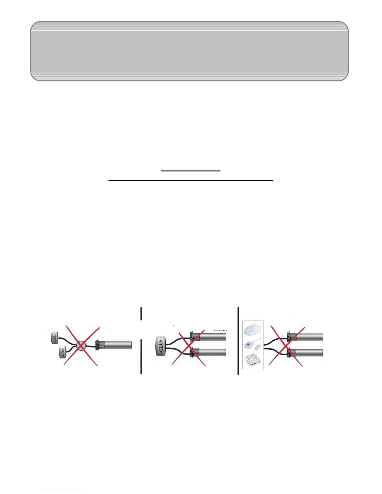
7. The screen / elevator cannot have connected more than one remote control at once.
8. One remote control (for ex. RC01 / RC02 / Trigger 12V / Trigger230V / IR Receiver / RS Receiver,
etc.) cannot be connected at once to more than one screen, elevator, roller-blind, etc. Such connection
can only be made by using the SG-2 group controller.
KAUBER InCeiling is a top-class electric projection screen, designed for installation in a suspended
ceiling. Its smartly designed aluminum housing has many installation aids. In the Tensioned version it is
additionally equipped with a special system to get an even more tense projection surface. The InCeiling
series was created for suspend ceilings in both conference rooms and home cinemas.
Switch
Switch
Screen / elevator
engine
Screen / elevator
engine
Screen / elevator
engine
Controls
Page 4
k
a u b
-4-
e r e
u
w w w
•
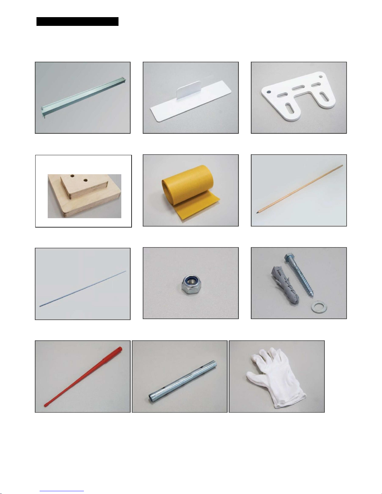
PACKAGE CONTENTS
projection screen - 1 pcs
mounting holes template. - 1 pcs
threaded rod - 4 pcs
engine adjustment wrench - 1 pcs
side panel - 2 pcs
main hole template - 1 pcs
M8 nut - 12 pcs.
tubular wrench 13 - 1 pcs
fixing support - 2 pcs
holes marker - 1 pcs
expansion dowel ø10 - 6 pcs
protective gloves - 2 pairs
Page 5
w w w . k
a u b
-5-
e r . e u
1. Carefully unpack the contents of the packaging, paying special attention to wooden sides that
protect the contents of the carton from damage. Remember that one of them functions also as a
template for mounting holes, so do not throw it out before the installation is finished!
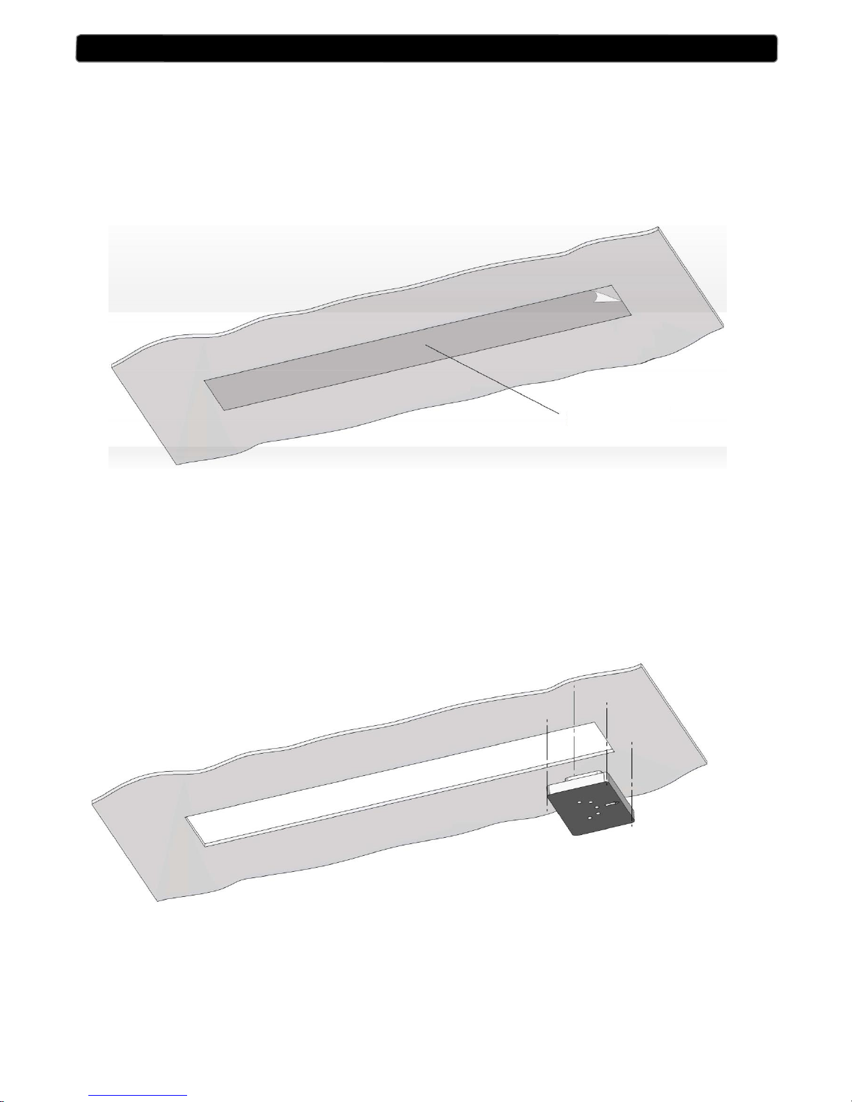
2. Stick the foil template of the main hole in the place designated for mounting the screen, and then outline
it with a pencil (Fig.1). After removing the foil, carefully cut in the ceiling the hole along the outline
made on the basis of the template.
Fig.1
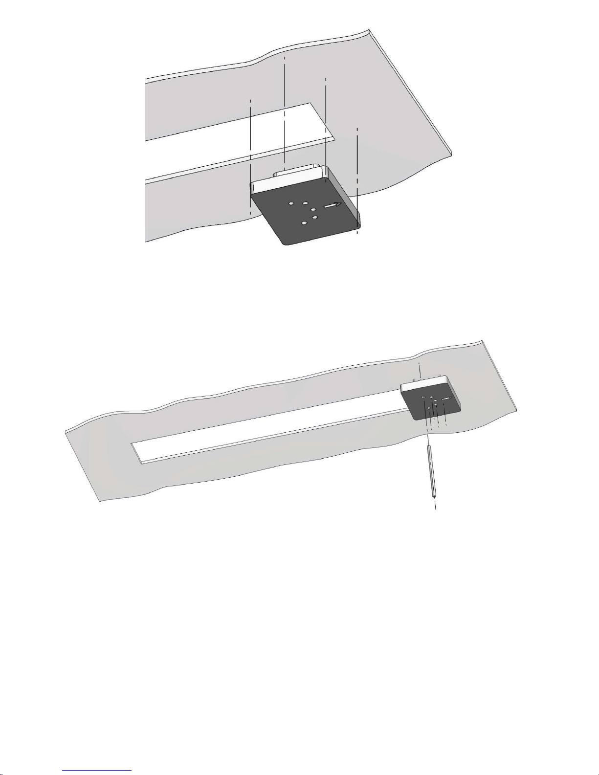
3. Put a wooden block protecting the contents of the cardboard at each of the two ends of the hole, so that
the arrow printed on it points to the outside of the hole (Fig.2, Fig.2a).
Fig.2
SCREEN INSTALLATION
TEMPLATE
Page 6
w w w . k
a u b
-6-
e r . e u
Fig.2a
4. Hold the template, and then guide the marker through the holes in the template to mark the drilling of
holes mounting in the fixed ceiling, (Fig.3).
Fig.3
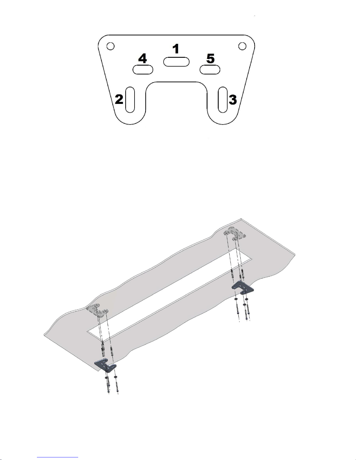
5. Using the ø10 drill, drill the holes for the mounting dowels in the marked places. The holes should be
drilled in the correct order, starting with the hole marked on the template with the number 1 (Fig.4).
After drilling the hole 1 correctly, move to drilling holes 2 and 3. Then, drill holes 4 and 5. Repeat for
the opposite side.
Page 7
w w w . k
a u b
-7-
e r . e u
Fig.4
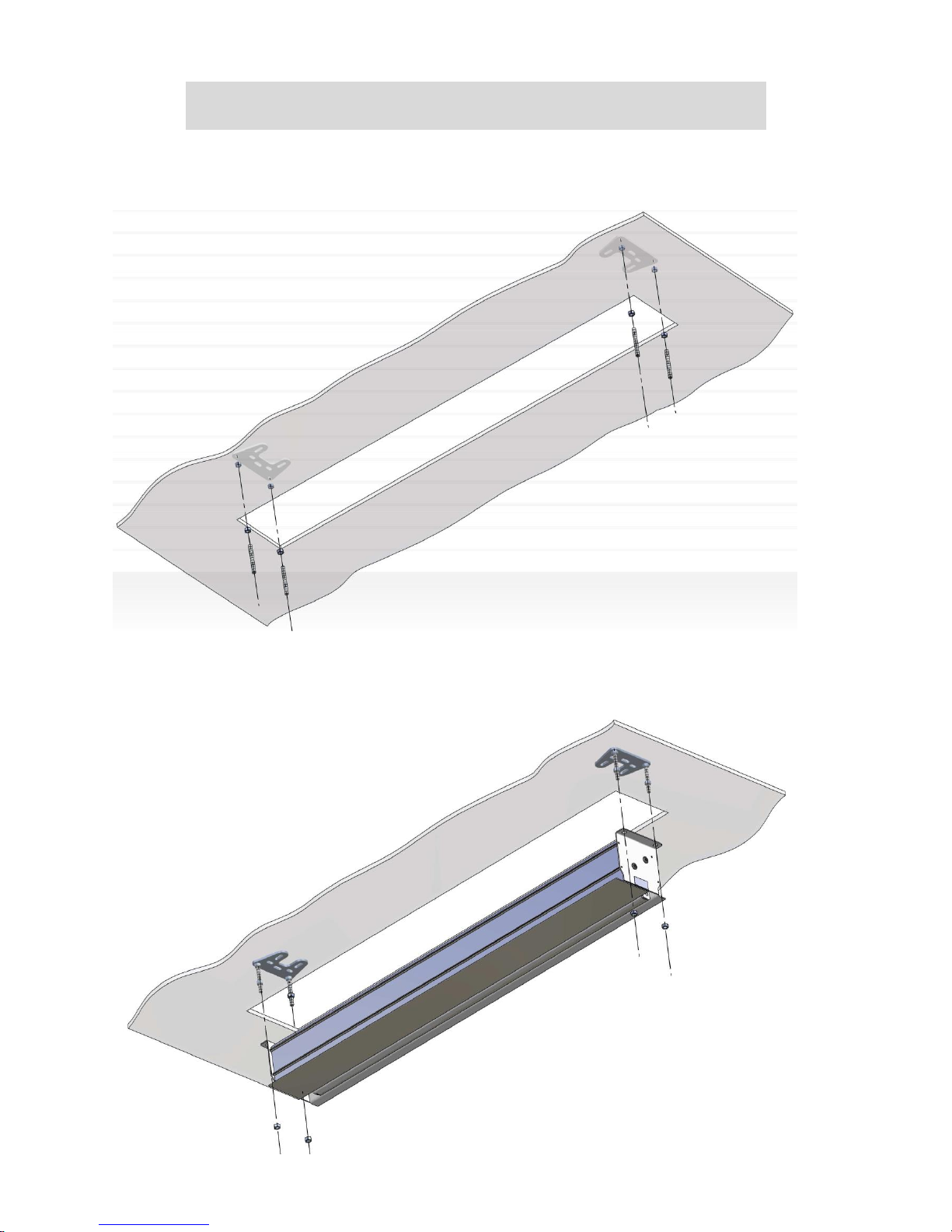
6. In place of the holes drilled in fixed ceiling, screw the mounting supports using the attached dowels and
screws (Fig.5).
NOTE! The mounting dowels supplied in the set can be used only for ceilings made of solid materials
(for ex. concrete, suporex). When attaching the screen to materials other than those listed, choose
appropriate mounting dowels.
Fig. 5
Page 8
-8-
7. Threaded rods have to be cut to the appropriate length using the following formula:
8. After cutting, each of the threaded rods should be screwed into a suitable hole in the mounting support,
and then countered with an M8 nut (Fig.6).
9. Tighten each of the mounted rods with an M8 nut at a distance of approx. 5-6 cm from the bottom end
of the rod, then try on the screen cassette. If necessary, adjust the position of the nut so that the
mounting brackets of the screen cassette rest on the nuts and the bottom edge of the cassette rests
against the suspended ceiling.
Fig.7
w w w . k a u b e r . e u
Fig.6
rod length =
distance between the fixed ceiling
and the bottom edge of the suspended
- 7 cm
Page 9
w w w . k
a u
-9-
b e r . e
u
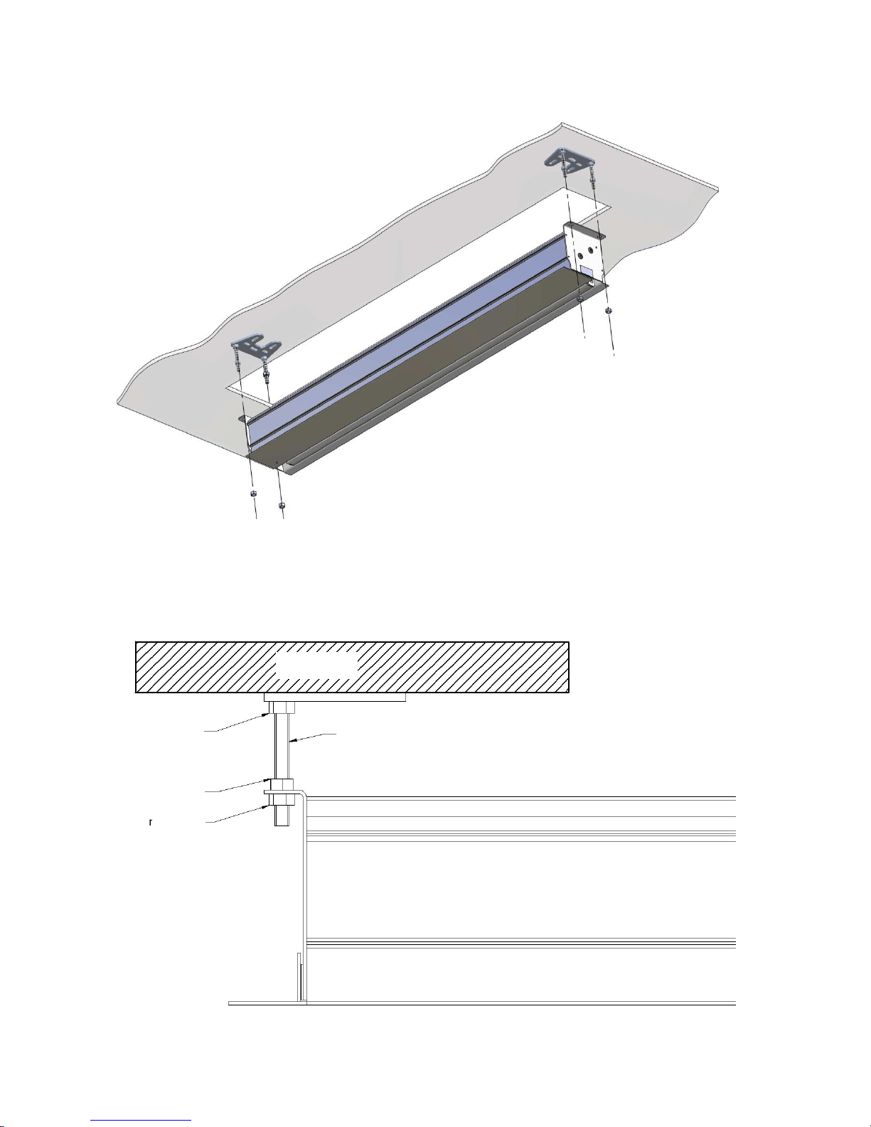
10. After connecting the power supply (see page no.15) slide the screen onto the mounted rods and screw
each of the 4 M8 nuts using the included pipe wrench while checking the stability of the entire
installation (Fig.8). A properly installed screen must be levelled. Correct the fixing by unscrewing or
screwing the mounting nuts on the appropriate threaded rods.
A properly installed screen is shown below (Fig.9). All connections are countered. Such an installation
protects the screen against the occurrence of vibrations and possible resonances. The movement of the
nuts 1 and 2 allows to accurately level the screen, which is required for the proper operation of the
screen.
Fig.9
Fig.8
CEILING
counter
Nut 1
Nut 2
Pin
SCREEN
Page 10
w w w . k
a u
-10-
b e r . e
u
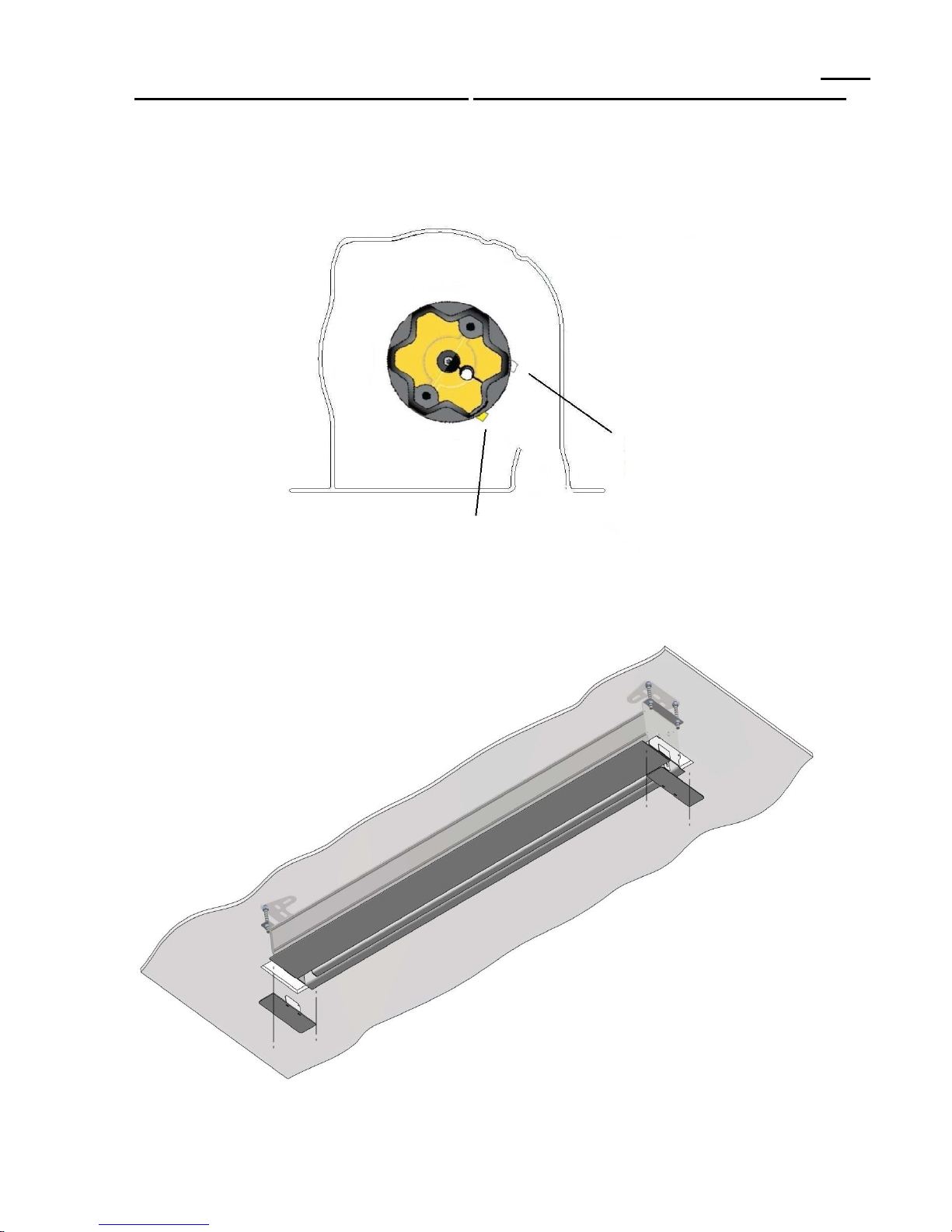
11. The delivered screen has end positions set in accordance with the order. If the surface of the screen
scrolls too low or not enough, correct the bottom end position using the included wrench. Before
adjustment, check in the warranty card with what type of engine is your screen equipped with.
NOTE! Adjustments to the end positions can only be made by a qualified person. All adjustments are
made at your own risk. In the event of an inaccurate adjustment, the screen may get damaged, which is
not covered by the terms of the warranty.
Fig.10
12. After final verification of the entire installation, place the side panels on magnets stuck to the panels
(Fig. 11). In screens with side tension, unfold the surface completely. If necessary, use the allen key to
adjust the tension with the bolts on both sides of the bottom bar.
Fig.11
White end stop
Yellow end stop
Access to the
end stop
Page 11
w w w . k
a u
-11-
b e r . e
u
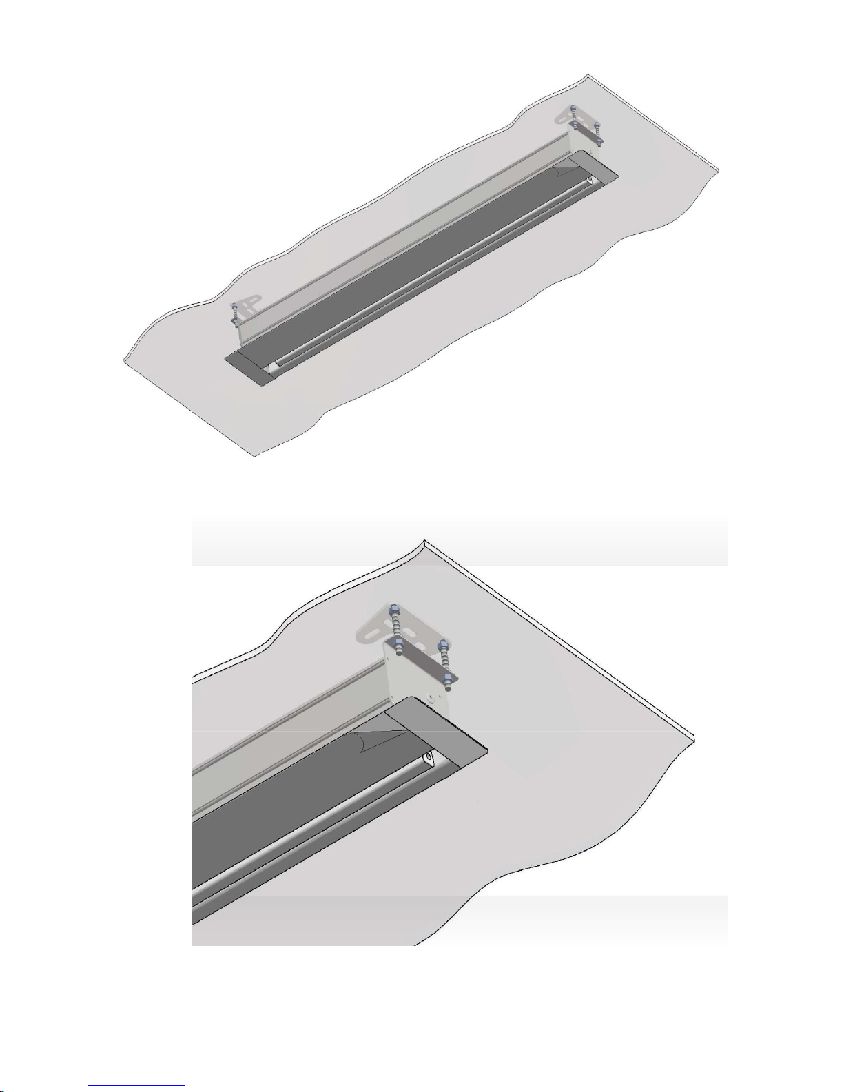
13. After completing the screen installation, peel off the foil protecting the cassette from damage (Fig.12,
Fig.12a).
Fig.12a
Fig.12
Page 12
w w w . k
a u
-12-
b e r . e
u
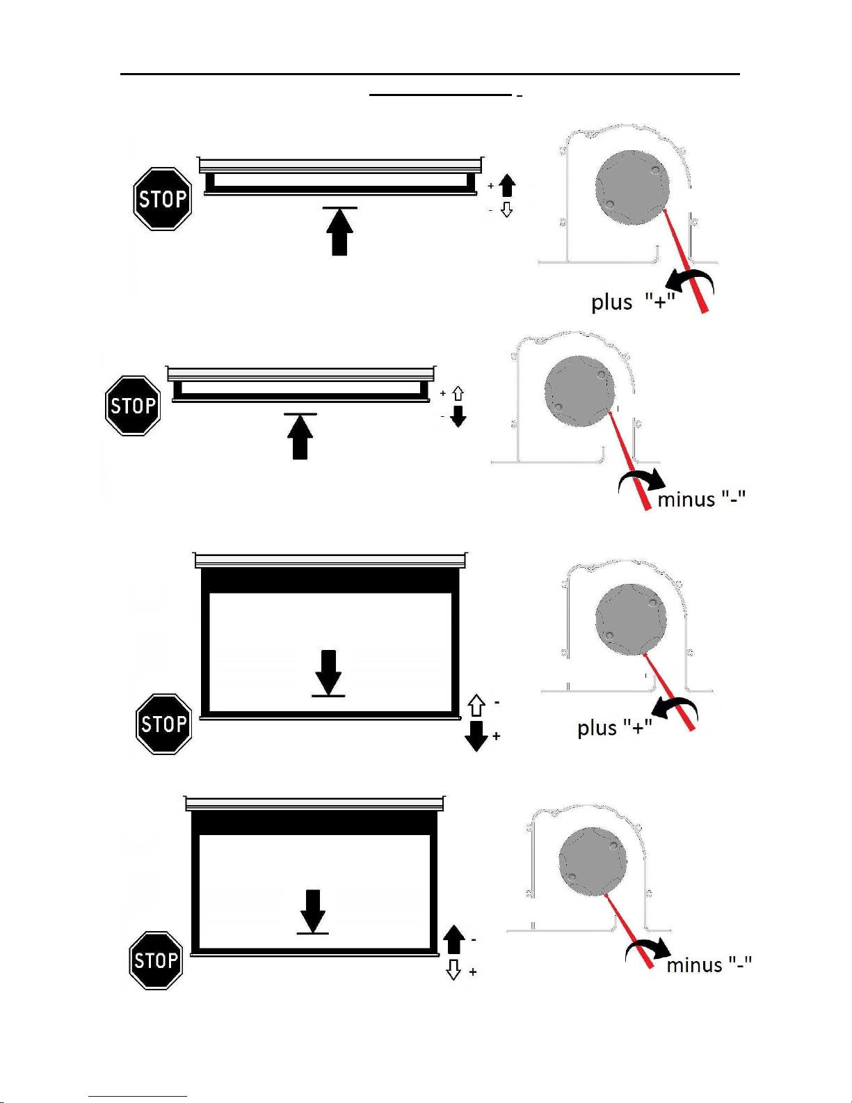
Adjusting the end positions (engine type "C" – you can check the engine type in
the warranty card )
- Correcting the bottom end position (yellow end stop).
Fig.15
Fig.16
- Correcting the top end position (white end stop).
Fig.13
Fig.14
White end stop
White end stop
Yellow end stop
Yellow end stop
Page 13
w w w . k
a u
-13-
b e r . e
u
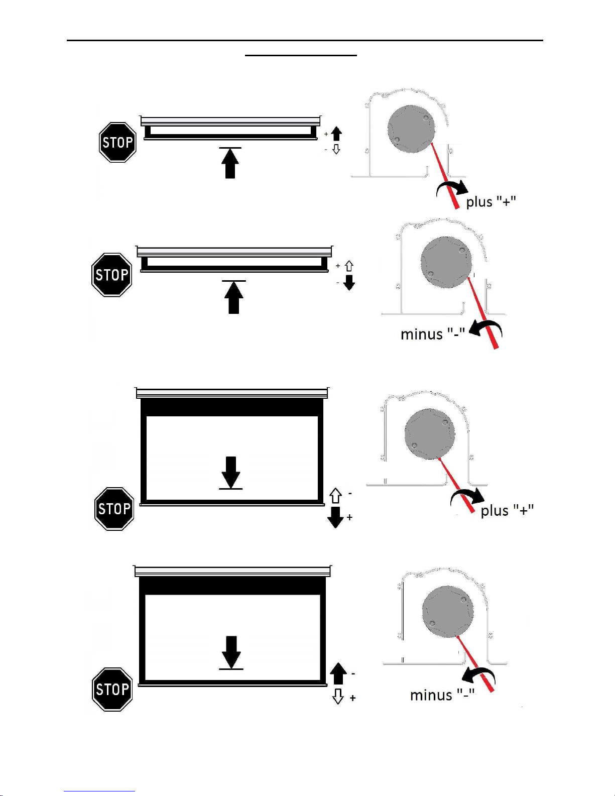
Adjusting the end positions (engine type "B" and "B-RTS" - check the engine type in
the warranty card))
- Correcting the top end position (white end stop).
Fig.17
Fig.18
- Correcting the bottom end position (yellow end stop).
Fig.19
Fig.20
White end stop
White end stop
Yellow end stop
Yellow end stop
Page 14
w w w . k
a u
-14-
b e r . e
u
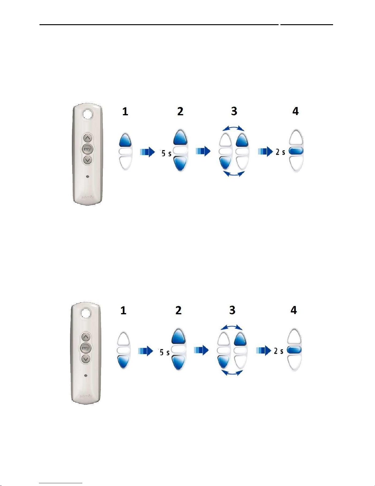
End positions adjustment (screen with built-in radio control – engine type "C-RTS")
Correcting the bottom end position:
1. Using the remote control button UP set the roller-blind in the top end position.
2. At the same time, press and hold for more than 5 seconds buttons UP and DOWN. The drive
moves briefly up / down.
3. Using the buttons UP, DOWN, STOP, set the roller-blind in the new end position.
4. Press and hold the button STOP for more than 2 seconds The drive moves briefly up / down
Fig. 21
Correcting the bottom end position:
1. Using the remote control button DOWN set the roller-blind in the bottom end position.
2. At the same time, press and hold for more than 5 seconds buttons UP and DOWN. The drive
moves briefly up / down.
3. Using the buttons UP, DOWN, STOP, set the roller-blind in the new end position.
4. Press and hold the button STOP for more than 2 seconds The drive moves briefly up / down
Fig.22
Page 15
w w w . k
a u
-15-
b e r . e
u
NOTE!
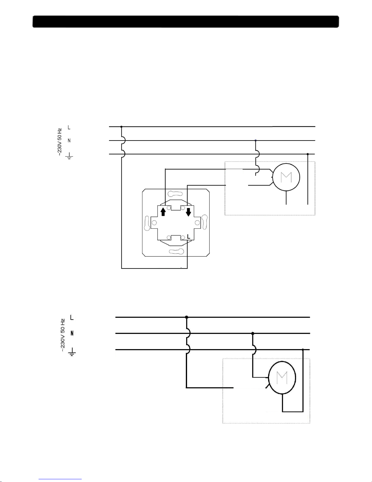
The screen may only be connected to the power supply by a person with appropriate electrical qualifications.
Before installing the screen cassette, lead the power supply cable to the place of installation and then connect it
to the screen during installation according to the diagram A (Fig.23A) or according to the diagram B in the case
of a screen with built-in radio control (Fig.23B).
.
Fig. 23A
DIAGRAM B (built-in radio control)
Fig.23B
DIAGRAM A
ELECTRICAL CONNECTION
Phase
Zero
Earthing
Black
Brown
Blue
Yellow-green
Screen engine
Key switch
Phase
Zero
Earthing
Brown
Blue
Yellow-green
Screen engine
Page 16
w w w . k
a u
-16-
b e r . e
u
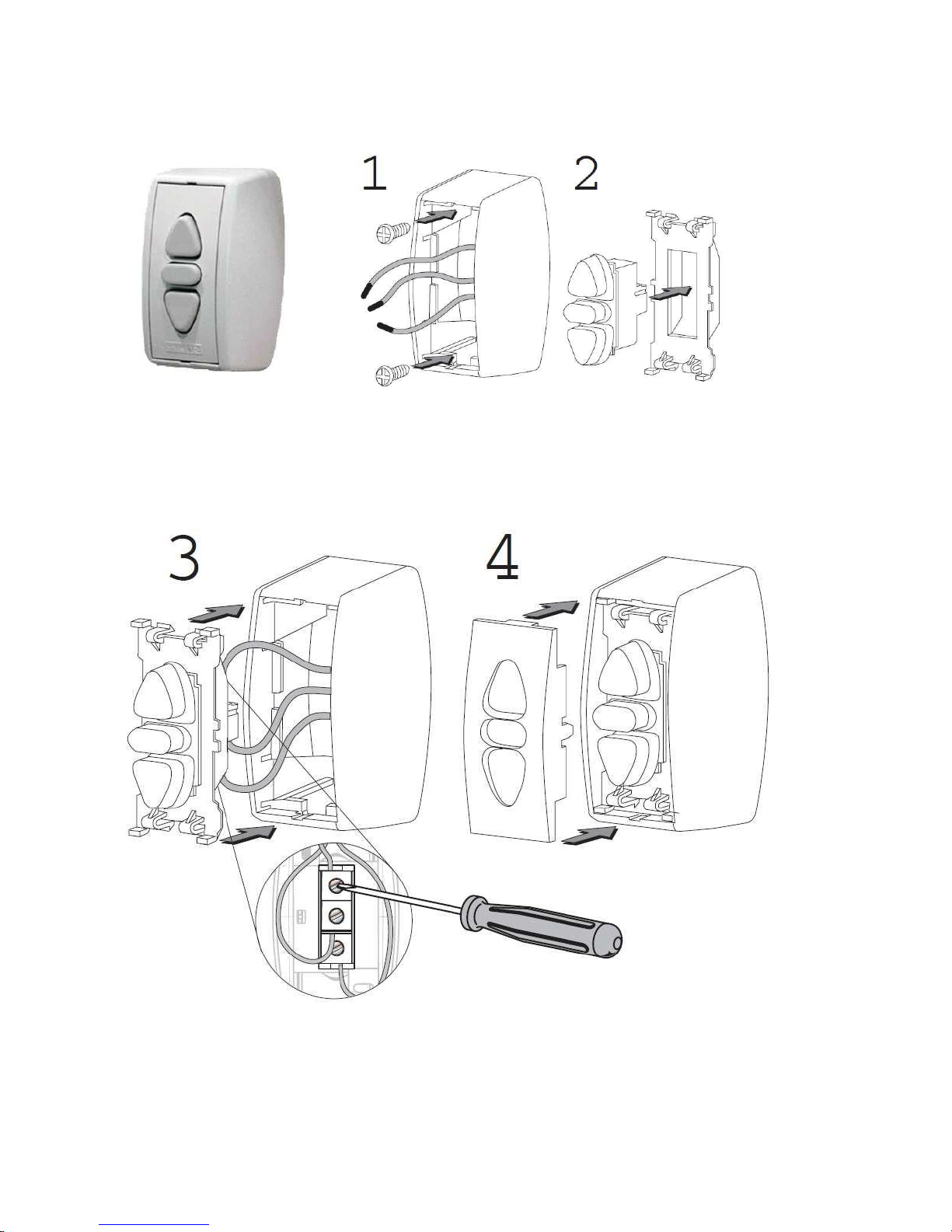
Connecting a key switch from the set.
(The switch is available in the set for screen without a built-in radio control)
Fig.24
Page 17
w w w . k
a u
-17-
b e r . e
u
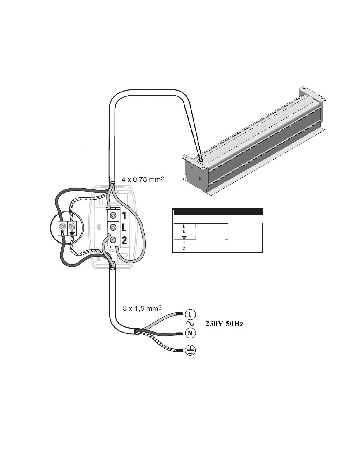
Diagram of connecting a key switch to the screen (screens with a "B" and "C" type
engine)
Fig.25
Contact Description Color
Phase (L)
Zero (N)
Earthing
Brown
Blue
Yellow-green
Black
Brown
Page 18
w w w . k
a u
-18-
b e r . e
u
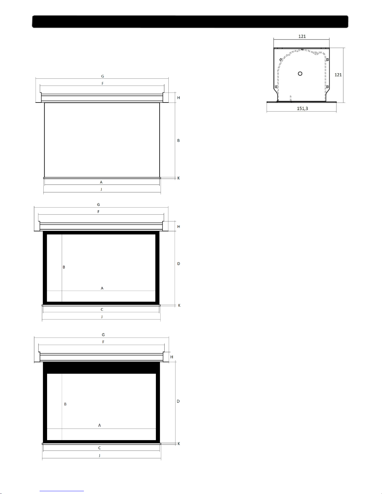
Housing dimensions:
INCEILING
A- surface width
B- surface height
F = A+108mm
J=A+30mm
K=50mm
H=121mm
G=A+148mm
INCEILING + BLACK FRAME
A- width of active surface
B - height of active surface
C = A +100mm
D=B+100mm
F=A+208mm
J=A+130mm
K=50mm
H=121mm
G=A+248mm
INCEILING + BLACK FRAME + BLACK
STRIP
A- width of active surface
B - height of active surface
C = A +100mm
D = B +50mm + black strip height
F = A +208mm
J=A+130mm
K=50mm
H=121mm
G=A+248mm
TECHNICAL DATA
Page 19
w w w . k
a u
-19-
b e r . e
u
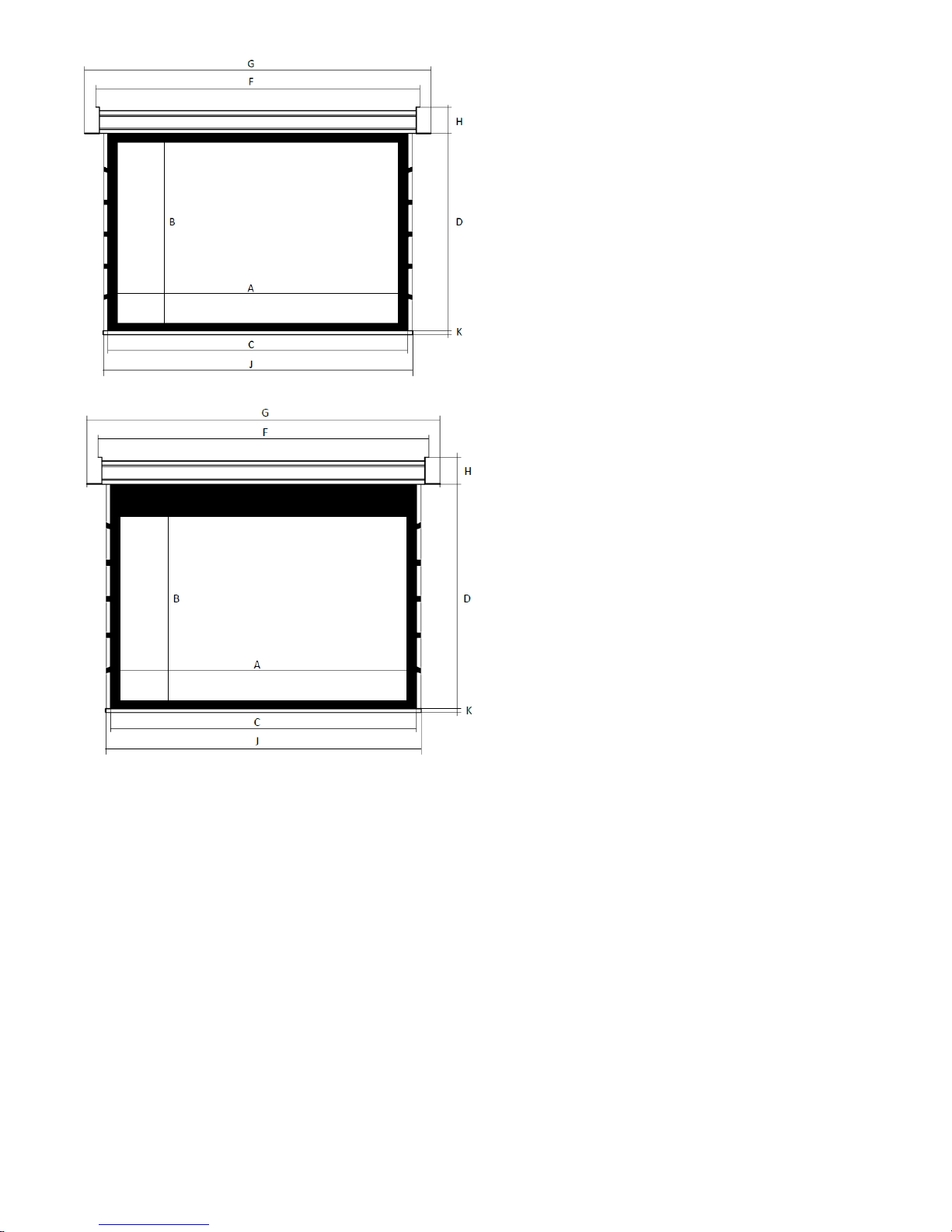
INCEILING + TENSIONERS
A- width of active surface
B - height of active surface
C = A +100mm
D=B+100mm
F=A+360mm
J=A+270mm
K=50mm
H=121mm
G=A+400mm
INCEILING + TENSIONERS + BLACK
STRIP
A- width of active surface
B - height of active surface
C = A +100mm
D = B +50mm + black strip height
F = A +360mm
J=A+270mm
K=50mm
H=121mm
G=A+400mm
Technical specifications:
Power supply: 230V 50Hz
Power: 120W – screen without a built-in radio control
120W – screen with built-in radio control
Page 20

w w w . k
a u
-20-
b e r . e
u
Thank you for choosing the KAUBER screen.
We invite you to purchase other KAUBER products
 Loading...