


Publication 350-01001-00, 01/19/2016
Instruction Manual
Installation • Operation • Maintenance
Please read this manual and all included manuals in its entirety
before unpacking, installing, and operating your generator. If your
manual came on a CD, read all the fi les included on the CD.
Kato EngineeringP.O. Box 8447 Mankato, MN USA 56002-8447Tel: 507-625-4011
Fax: 507-345-2798Email:
Copyright © 2015 Kato Engineering, Inc. All rights reserved
KatoEngineering@emerson.com www.kato-eng.com
Standard AC generator
Single or two-bearing
Drive-end air discharge
Copyright © 2012 Kato Engineering, Inc. All rights reserved
Page 1

Notice: Because of rapid changes in
designs and processes and the variability of
Kato Engineering’s products, information in
this manual must not be regarded as binding
and is subject to change without notice.
The image on the front cover is representative only. Several variations are available
within the range of generators covered
within this manual.
Table of Contents
Introduction......................................................... 4
Foreword............................................................................ 4
Safety instructions.............................................................. 4
Ratings/description............................................................ 4
Construction and Operating Principles............ 5
Stator ................................................................................. 5
Rotor.................................................................................. 5
Bearings............................................................................. 5
Connection boxes.............................................................. 6
Excitation system............................................................... 6
Optional PMG system........................................................ 7
Other options..................................................................... 7
Installation........................................................... 8
Receiving inspection.......................................................... 8
Unpacking and moving...................................................... 8
Location............................................................................. 8
Base design....................................................................... 8
Assemble to prime mover, alignment................................ 8
Two-bearing close-coupled alignment.....................9
Two-bearing alignment...........................................14
Single-bearing alignment........................................18
Foot defl ection................................................................. 23
Doweling.......................................................................... 23
Electrical connections...................................................... 23
Space heaters................................................................. 23
Inspection before startup................................................. 23
Operation........................................................... 25
Initial startup: generators w/auto & manual control.......... 25
Initial startup: generators w/auto control only................... 25
Restoring residual magnetism/fi eld fl ashing.....................26
Continuous operation....................................................... 27
Idling................................................................................. 27
Parallel operation.............................................................. 27
Copyright © 2012 Kato Engineering, Inc. All rights reserved
Page 2

Maintenance....................................................... 30
Schedules........................................................................30
Maintenance procedures................................................. 32
Visual inspection methods of windings.................. 33
Cleaning................................................................ 35
Insulation resistance tests at low voltage.............. 35
Dry out procedures............................................... 36
Bearing lubrication................................................ 36
Rectifi er tests........................................................ 37
Disassembly ..................................................................... 39
Overall disassembly............................................... 39
Exciter armature and PMG removal...................... 40
Bearing removal.................................................... 42
Assembly .......................................................................... 43
Bearing installation................................................ 43
Overall assembly................................................... 43
Exciter armature and PMG installation.................. 43
Storage............................................................................ 45
Torque chart..................................................46-47
Troubleshooting Guide..................................... 48
Main part location............................................................. 51
List of equipment required for installation
and maintenance............................................................. 52
Page 3
Copyright © 2012 Kato Engineering, Inc. All rights reserved
WARNING: Shock hazard - Do not
service the generator or other electrical
machinery without de-energizing and
tagging the circuits as out of service.
Dangerous voltages are present, which
could cause serious or fatal shock.
NOTICE: For specifi c lubrication
instructions, always refer to the bearing
lubrication sheet that came with your
manual or the lube plate on the generator.
Unauthorized lubricants may result in a
bearing failure.
Introduction
Foreword
This manual contains instructions for installing, operating and
maintaining Kato Engineering AC brushless revolving fi eld generators.
These generators are manufactured in many sizes and ratings and with
various options.
Lubrication information, electrical connection drawings, dimensional
drawings and parts listings for your model are contained in the manual
package as supplementary information and are the specifi c source of
information for making connections and ordering replacement parts.
Information about optional components of your generator may also be
contained as a supplement.
Please read this manual and all included manuals in its entirety before
unpacking, installing, and operating your generator. If your manual
came on a CD, read all the fi les included on the CD.
Safety instructions
In order to prevent injury or equipment damage, everyone involved in
installation, operating and maintenance of the generator described in this
manual must be qualifi ed and trained in the current safety standards that
govern his or her work.
While “common-sense” prevention of injury or equipment damage
cannot be completely defi ned by any manual (nor built into any piece of
equipment), the following paragraphs defi ne warnings, cautions, Notices
and Important as they are used in this manual:
WARNING: Warnings identify an installation, operating or
maintenance procedure, practice, condition, or statement that, if not
strictly followed, could result in death or serious injury to personnel.
CAUTION: Cautions identify a hazardous situation that if not
avoided could result in minor or moderate injury.
NOTICE: Notices identify an installation, operating or maintenance
procedure, practice, condition, or statement that, if not strictly followed,
could result in destruction of or damage to equipment or serious
impairment of system operation.
IMPORTANT: Important messages are informational only.
Ratings/description
Nameplates, which are located on the side of the generator, include
serial and model number as well as rating information and bearing and
lubrication information.
Copyright © 2012 Kato Engineering, Inc. All rights reserved
Page 4

Construction and Operating Principles
Stator
The stator consists of the supporting frame, core, and armature windings.
The stator core is made from laminations, thin sheets of electrical steel,
which are stacked and held in place by steel endrings and support
bars. The rings and bars are welded to or are part of the steel frame.
Base mounting plates are welded to the bottom of the frame. The base
mounting plates allow the assembly to be mounted on the genset base.
The windings (coils) are constructed of layered and insulated copper
wire. The coils are inserted in the core slots, connected together, and
the entire assembly is vacuum-pressure impregnated with resin. Stator
leads terminate in standard connection lug or strap terminals for ease of
connection to the load.
Rotor
The main rotor assembly is the revolving fi eld. It consists of windings
in a core, which is in turn mounted on a steel shaft. The exciter armature
assembly and optional permanent magnet generator (PMG) rotor are also
mounted on the shaft as are the fan(s) and other optional accessories.
The core consists of laminations, thin sheets of electrical steel, which are
stacked together. The core makes the salient poles (four, six, eight or 10).
With six or more poles, the poles are typically attached to a center hub.
The rotor windings consists of insulated magnet wire wound around
each pole. V-blocks between each pole keep the rotor windings in place.
Damper windings consist of copper or aluminum rods that are inserted
through each pole surface and are brazed to copper or aluminum damper
end plates at each end of the lamination stack. The end plates are brazed
to adjacent poles to form a continuous damper winding.
windings are supported with bars or aluminum pole shoes. The rotor
either has resin applied during the winding process or is vacuum-pressure
impregnated with resin.
The ends of the
NOTICE: Generators equipped with sleeve
oil bearings must have oil added to the
bearing prior to rotation. Failure to comply
will result in bearing damage. See the
bearing manual.
The shaft is made from high-strength rolled or forged steel and machined
to accommodate all the rotating generator components. Keyways in
the shaft ensure precise positioning of the rotor, exciter armature, and
optional PMG rotor as well as drive couplings. On the exciter side, the
shaft has a slot or hole in its centerline for running the revolving fi eld
leads to the rectifi er.
Bearings
The generator may contain either one or two bearings. Bearings are
typically ball or roller type and are regreaseable bearings, which contain
fi ll and drain ports for easy lubrication. Sleeve bearings are optional
on some designs. A supplementary instruction will be included in
NOTICE: For specifi c lubrication
instructions, always refer to the bearing
lubrication sheet that came with your
manual or the lube plate on the generator.
Unauthorized lubricants may result in a
bearing failure.
Copyright © 2012 Kato Engineering, Inc. All rights reserved
Page 5

the manual package for sleeve bearings if they are applicable to this
generator. Some smaller generators may use heavy duty double shielded
bearings, which are typically used on smaller generators and are greased
for life.
Connection boxes
The main lead connection box houses the load lead terminals. In
addition, the generator may have auxiliary connection boxes for
connecting temperature detector outputs, space heater connectors, and
sensing outputs.
Excitation system
The excitation system consists of the exciter stator assembly and the
exciter armature assembly:
The exciter stator assembly consists of windings in a core. The core is
made from steel laminations that are stacked and welded together. The
main exciter stator coils are placed in slots in the core and form alternate
north and south poles. The entire assembly is either mounted to the end
bracket or mounted in a frame, which is mounted to the end bracket. The
stator is a stationary fi eld, which is powered by the voltage regulator.
The assembly consists of two subassemblies: the exciter armature and
the rotating rectifi er. The exciter armature assembly contains steel
laminations that are stacked and keyed on the shaft or on to a sleeve,
which is keyed to the generator shaft. A three-phase winding is inserted
into slots in the laminations. The coils are held in place by insulating
wedges. The coil extensions are braced with tape. Output leads from the
winding are connected to the rotating rectifi er assembly.
The rotating rectifi er is a three-phase full wave bridge rectifi er,
converting the AC from the exciter armature to DC, which is transferred
to the revolving fi eld windings. Two aluminum steel plates, each
containing three rotating rectifi er diodes, are mounted on each side of
an insulating hub to form the negative and positive terminals. The plates
also act as heat sinks for the diodes.
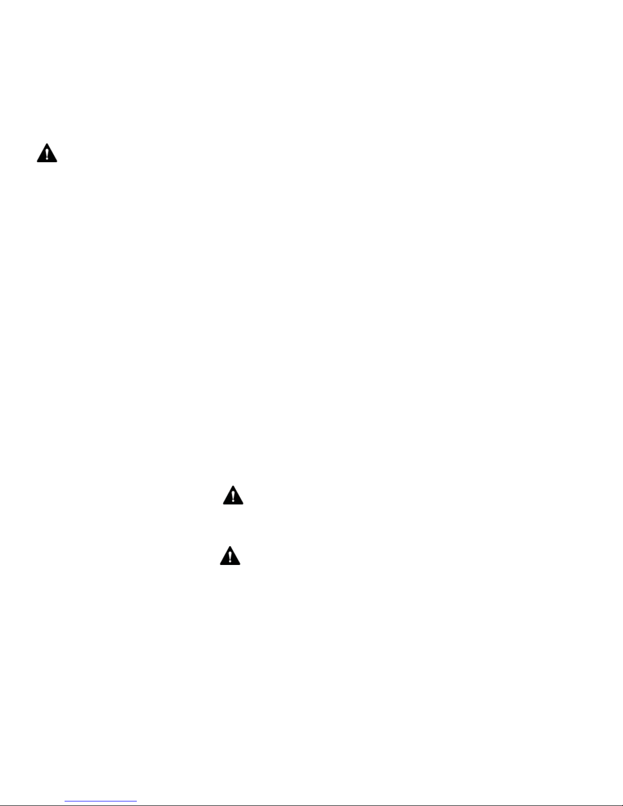
Excitation system functional overview: Exciter fi eld control is
established by the strength of the exciter fi eld current developed by
the voltage regulator system. The DC voltage and current levels of the
exciter fi eld signal from the voltage regulator varies depending upon the
generator output voltage and the loading of the output lines (see Figure
1).
Copyright © 2012 Kato Engineering, Inc. All rights reserved
Page 6
Power input
Voltage
regulator
Output leads
Main stator
PMG stato
(armature)
PMG rotor
(fi eld)
r
Exciter
armature (AC)
Figure 1: Overview of excitation system
(with an optional PMG)
Exciter stato
(fi eld)
r
Rectifi er
(armature)
Main rotor (DC)
Optional PMG system
The permanent magnet generator (PMG) system consists of the PMG
stator and PMG rotor:
The PMG stator is a stationary armature and is located within the stator
assembly that also contains the exciter stator or is a separate stator
mounted next to the exciter stator. The PMG stator consists of steel
laminations. The laminations are held in place by steel compression rings
and are welded to the frame bars of the exciter-PMG frame. The PMG
windings are placed in slots in the laminations. Insulating wedges are
inserted at the top of each slot to hold the coils in position.
Prime mover
Shaft
The PMG rotor consists of rectangular permanent magnets and cast pole
tips secured to a steel hub with nonmagnetic stainless steel bolts. The
PMG rotor is keyed to the shaft and secured with a nut and lock washer.
PMG system overview: The PMG system functions as a pilot exciter,
providing power to the automatic voltage regulator power supply. The
PMG is an AC generator that uses permanent magnets in the rotor instead
of electromagnets to provide the magnetic fi eld (see Figure 1).
Other options
Other options include, but are not limited to, space heaters, fi lters, and
temperature sensing devices.
Page 7
Copyright © 2012 Kato Engineering, Inc. All rights reserved

WARNING: Electric shocks can occur
from faulty ground connections on portable
electrical equipment and failure to ground
stationary equipment which may result in
death or injury. Be alert at all times when
installing, operating and maintaining the
generator. Avoid contact with the uninsulated
metal parts of the generator. Test all portable
devices frequently to prove that a solid
electrical circuit exits from the metal frame
though the grounding conductor, in the
electrical cord, to the grounding contact in
the attachment plug. Do not use electrical
equipment with frayed, burned or damaged
cords.
Always take extreme care when moving the
generator. Be careful to not strike objects or
personnel.
Installation
Receiving inspection
Before accepting a shipment, examine the packaging for any sign of
damage that might have occurred during transit. Report any damage to
the transportation company and Kato Engineering.
Unpacking and moving
If the generator is received during cold weather, reduce condensation on
cold surfaces and failure due to wet windings by allowing the generator
to reach room temperature before removing the protective packing.
Unpack the generator carefully to avoid scratching painted surfaces. Do
not remove the protecting lubricant from the shaft end or drive plates.
Inspect for loosely mounted components and the presence of moisture.
Inspect to make certain foreign material, such as crating nails, loose
bolts or packing material, which may have fallen into the machine during
unpacking, is removed. If damage is Noticed, determine the extent of
damage and immediately notify the transportation company claims offi ce
and Kato Engineering. Be sure to give complete and accurate details
when reporting damage.
WARNING: Apply lifting force to
structural points specifi cally provided for
lifting. Do not use the enclosure lifting holes
to lift the whole unit. Use lifting means
adequate for the weight. Observe lifting
notices attached to the generator. Failure
to observe these instructions can result in
injury, death and damage to the generator.
NOTICE: Do not attempt to transport a
single-bearing generator without maintaining
proper rotor support and with the exciter
rotor assembly removed. Failure to observe
this warning can result in equipment
damage.
NOTICE: Blocking or restriction of normal air
fl ow into or out of the generator may cause
damage to the electrical windings.
Move the generator by attaching an overhead hoist to the eyebolts
installed on the generator frame or by lifting the generator from
underneath the skid with a forklift.
Single-bearing generators are shipped with the exciter rotor assembly
removed from the shaft and a support mounted across the drive discs to
support the rotor.
Location
Install the generator in an area so it complies with all local and industrial
regulations. Locate it in a clean, dry, well-vented area or area that is
suitable for the generator enclosure. Make sure it is easily accessible for
inspection and maintenance.
Check winding insulation resistance before placing the generator in
operation (see the maintenance section).
Protect generators operating intermittently in very damp locations with
space heaters. Slowly warm generators placed in operation after being
subjected to very low temperatures to prevent excessive condensation.
Base design
The type of base to be used will depend upon the nature of the
installation site. However, the generator base must be rigid, level, and
free from vibration. Mounting holes must be larger than the fasteners to
allow for alignment.
Copyright © 2012 Kato Engineering, Inc. All rights reserved
Page 8

Assemble to prime mover, alignment
Follow either the two-bearing alignment (if your generator model has
two bearings but no adapter to bolt to an engine fl ywheel housing),
two-bearing close-coupled alignment (if your generator model has two
bearings and an adapter for bolting to a fl ywheel housing), or single-
bearing alignment (if your generator has one bearing and drive plates).
Consult the factory for belt or gear drive alignment).
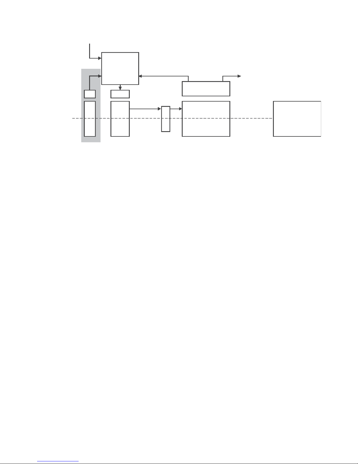
Two-bearing close-coupled alignment
Check the engine fl ywheel housing pilot’s radial and face runout by
mounting a dial indicator and measuring the fl ywheel to the fl ywheel
housing as shown in Figure 2. See Table 1 for maximum allowable
runout.
Flywheel
Dial indicator
pointer for radial
runout
Dial indicator pointer for
face runout
Figure 2: Flywheel housing check
Flywheel housing
NOTICES:
Mounting of the indicators must allow
complete rotation of the prime mover.
Shaft
Use dial indicators that are rigid so indicator
sag won’t be a factor. Using the shortest
offset distance of the indicator bracket will
reduce the effects of indicator droop or sag.
During alignment, you may also need to
compensate for engine expansion due to
heating. Generator expansion is generally
not considered a factor.
If the genset is moved to a different
location, check alignment before startup.
WARNING: Do not pry on the
generator fan blades. The blades can
weaken, which could result in serious injury
or death from fl ying debris.
Page 9
Copyright © 2012 Kato Engineering, Inc. All rights reserved

SAE housing
number
Housing inside
dia.
Allowable
runout (TIR)
NOTICE: TIR = Total indicated runout
6
5
4
3
2
1
0.5
0
00
10.500
12.375
14.250
16.125
17.625
20.125
23.000
25.500
31.000
0.002
0.003
0.003
0.004
0.004
0.005
0.005
0.006
0.007
Table 1: Maximum allowable
fl ywheel housing runout (inches)
Check the engine fl ywheel’s radial and face runout by mounting a dial
indicator and measuring the fl ywheel housing to the fl ywheel as shown
in Figure 3. The maximum allowable fl ywheel runout is .0005” per inch
of radius with a maximum of .010”.
Flywheel
NOTICE:
Compensation for engine
thermal growth must be taken into
account on this measurement.
Dial indicator pointer
for radial runout
Dial indicator
pointer for face
runou
t
Figure 3: Flywheel check
Flywheel housing
Shaft
Copyright © 2012 Kato Engineering, Inc. All rights reserved
Page 10
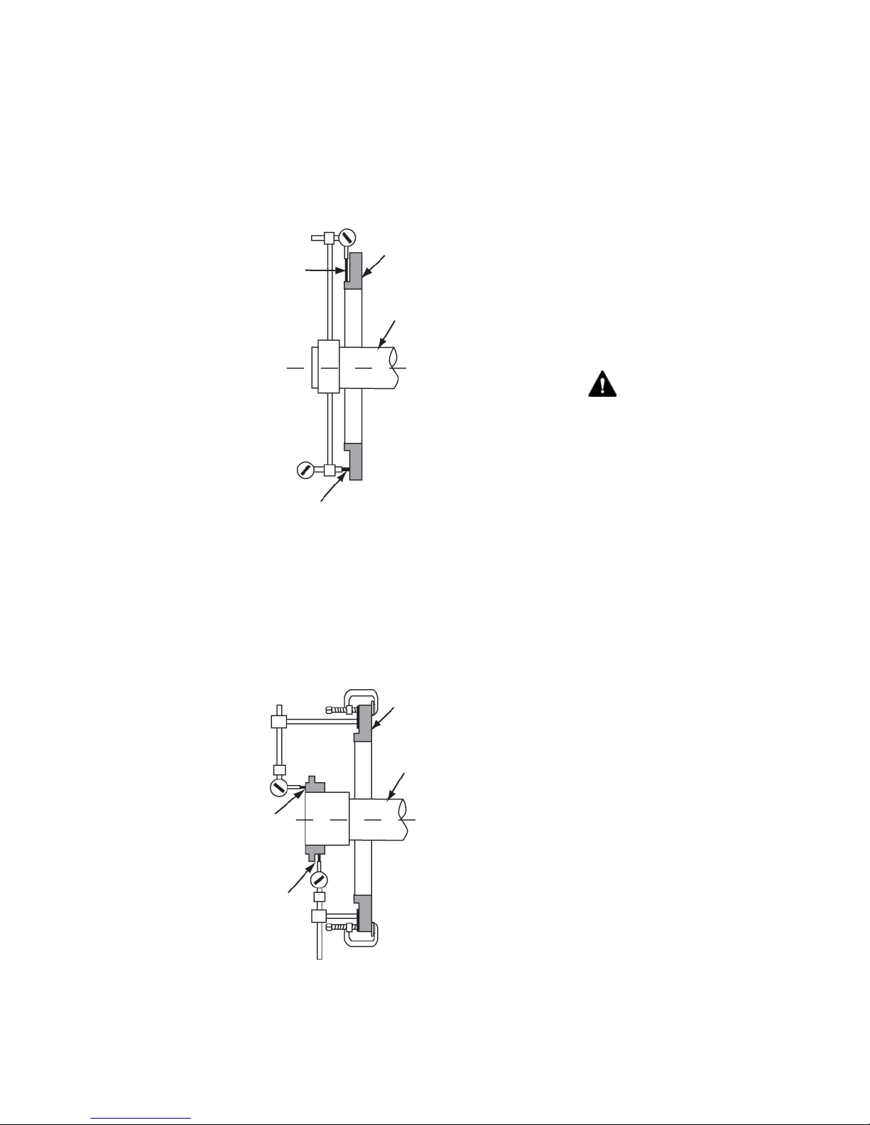
Check the generator adapter’s radial and face runout by mounting a
dial indicator on the generator shaft or coupling as shown in Figure 4.
The maximum radial and face runout on the generator adaptor must not
exceed 0.010 inch.
NOTICES: Mounting of the indicators must
allow complete rotation of the prime mover.
Use dial indicators that are rigid so indicator
sag won’t be a factor. Using the shortest
offset distance of the indicator bracket will
reduce the effects of indicator droop or sag.
Dial indicator pointer
Adapter
for radial runout
Shaft
Dial indicator
pointer for face
runout
Figure 4: Generator adapter check
Check the generator coupling’s radial and face runout by mounting
a dial indicator to the generator adapter as shown in Figure 5. The
maximum radial and face runout on the coupling must not exceed 0.003
inch.
During alignment, you may also need to
compensate for engine expansion due to
heating. Generator expansion is generally
not considered a factor.
If the genset is moved to a different
location, check alignment before startup.
WARNING: Do not pry on the
generator fan blades. Blades can weaken
which could result in serious injury or death
from fl ying debris.
NOTICE: Generators equipped with sleeve
oil bearings must have oil added to the
bearing prior to rotation. Failure to comply
will result in bearing damage. See the
bearing manual.
Dial indicator
pointer for face
runout
Dial indicator
pointer for radial
runout
Figure 5: Generator coupling check
Adapter
Shaft
Copyright © 2012 Kato Engineering, Inc. All rights reserved
Page 11

Install the portion of the coupling that fi ts into the engine fl ywheel
following the manufacturer’s recommended procedures and in accordance with engine manufacturer’s specifi cations. Check the coupling’s
radial and face runout by mounting a dial indicator to the engine
fl ywheel housing as shown in Figure 6. The maximum radial and face
runout on the coupling must not exceed 0.004 inch.
Measure and record the engine crank shaft endplay Set the engine
endplay at a position of one half of the measured distance.
Measure the generator endplay. Compare the measured endplay to the
factory recorded endplay located on the Generator Warranty/Test Tag.
Once this is verifi ed, thrust the generator shaft all the way to the engine,
then back off that location .020”, or .508mm. This will allow for the
thermal growth of the shaft.
Flywheel
IMPORTANT: The maximum allowable
fl ywheel runout is .0005” per inch of radius
with a maximum of .010”.
Flywheel housing
Dial indicator
pointer for face
runout
Dial indicator pointer
for radial runout
Figure 6: Engine coupling check
Shaft
Mount the generator on the skid, and move the generator to within 0.010
inch of the engine. Place two 0.010-inch shims in the horizontal
(9 o’clock and 3 o’clock) positions between the generator adapter
and the engine fl ywheel housing. Raising the rear, exciter end of the
generator as necessary, place two 0.010-inch shims in the vertical (6
o’clock and 12 o’clock) positions between the generator adapter and
the engine fl ywheel housing. This will give a good starting point for
alignment. Remove the vertical shims at this time. (If necessary, mark
holes to be drilled on the base, and remove the generator at this time.)
Mount a dial indicator on the generator shaft or half coupling to the
fl ywheel radial surface for parallel alignment as shown in Figure 7.
Copyright © 2012 Kato Engineering, Inc. All rights reserved
Page 12

Mount a dial indicator on the fl ywheel coupling to the face of the
generator half coupling for angular alignment as shown in Figure 7.
Align the engine by rotating the prime mover in 90-degree incre ments
and measuring total indicator runout. Tighten the generator to the base
before taking each set of readings. Raise or lower the generator by
adding or removing shims under the machined feet.
Flywheel
Dial indicator pointer
for parallel alignment
Flywheel housing
Shaft
Dial indicator pointer
for angular alignment
Figure 7: Alignment check
Following the fi nal generator adjustment and runout check, remove
the horizontal shims from the adaptor fl ywheel housing, and move the
generator all the way to the adaptor. Then tighten the fasteners.
Recheck alignment. Make sure angularity (face) total indicated runout
does not exceed 0.005 inch per inch of generator coupling diameter and
parallel (radial) total indicated runout does not exceed 0.005” TIR.
IMPORTANT: Clearances between the
adaptor pilot and the fl ywheel housing
recess are designed to meet the tolerance
of 0.001 to 0.015 inches.
Torque the fasteners to the value shown in Table 3.
Page 13
Copyright © 2012 Kato Engineering, Inc. All rights reserved

Two-bearing alignment
Follow the tolerances specifi ed by the coupling manufacturer when they
are less than described in this manual.
Use shims, if necessary, between the mounting pad and the base to
properly level and align the generator to the prime mover.
Install the coupling(s) on the generator and engine drive shafts in
accordance with coupling manufacturer installation procedures. Check
the generator coupling’s radial and face runout by mounting a dial
indicator to the generator adapter as shown in Figure 8. The maximum
radial and face runout on the coupling must not exceed 0.003 inch.
Adapter
Shaft
Dial indicator
pointer for face
runout
Dial indicator
pointer for radial
runout
Figure 8: Generator coupling check
Install the portion of the coupling that fi ts into the engine fl ywheel
following the manufacturer’s recommended procedures and in accordance with engine manufacturer’s specifi cations. Check the coupling’s
radial and face runout by mounting a dial indicator to the engine
fl ywheel housing as shown in Figure 9. The maximum radial and face
runout on the coupling must not exceed 0.004 inch. Measure and record
the engine crank shaft endplay Set the engine endplay at a position of
one half of the measured distance.
Measure the generator endplay. Compare the measured endplay to the
factory recorded endplay located on the Generator Warranty/Test Tag.
Once this is verifi ed, thrust the generator shaft all the way to the engine,
then back off that location .020”, or .508mm. This will allow for the
thermal growth of the shaft.
Copyright © 2012 Kato Engineering, Inc. All rights reserved
If the generator has “fl oating bearings”, align the face of the outer seat
with the groove in the shaft (electrical center).
Page 14
Dial indicator
pointer for face
runout
Dial indicator pointer
for radial runout
Figure 9: Engine coupling check
Flywheel
Flywheel housing
Shaft
Use a straight edge and a thickness gauge for rough alignment as shown
in Figure 10. Check for angular and parallel alignment as follows:
Straight edge
Thickness gauge
Figure 10: Rough alignment
Page 15
Copyright © 2012 Kato Engineering, Inc. All rights reserved

Angular alignment: Fasten a dial indicator to one of the coupling halves,
and scribe the position of the dial button on the face of the opposite
coupling half as shown in Figure 11. Rotate both shafts simultaneously,
keeping the fi nger or button on the indicator at the reference mark on the
coupling hub. Notice the reading on the indicator dial at each one quarter
revolution.
A variation of readings at different positions will indicate how the
machine needs to be adjusted to obtain a maximum misalignment of
0.005 inch for each inch of the coupling hub’s radius, total indicator
runout. Place or remove slotted shims from under the front or rear engine
or generator mounting pads and/or shift the front or back half of one
component from side to side until the components are properly aligned.
Tighten the mounting bolts, and recheck alignment.
Dial indicator
Copyright © 2012 Kato Engineering, Inc. All rights reserved
Figure 11: Angular alignment
Parallel alignment: Fasten a dial indicator to one of the coupling halves,
and scribe the position of the dial button on the top of the opposite
coupling half as shown in Figure 12. Rotate both shafts simultaneously,
keeping the fi nger or button on the indicator at the reference mark on the
coupling hub. Notice the reading on the indicator dial at each one quarter
revolution. A variation of readings at different positions will indicate how
the machine needs to be adjusted to obtain a maximum misalignment of
0.005 TIR. Compensation for engine thermal growth must be taken into
account on this measurement. Place or remove slotted shims from under
all of the engine or generator mounting pads and/or shift one component
from side to side until the components are properly aligned. Tighten the
mounting bolts, and recheck alignment.
Page 16
Dial indicator
Figure 12: Parallel alignment
Page 17
Copyright © 2012 Kato Engineering, Inc. All rights reserved
NOTICES: Mounting of the indicators must
allow complete rotation of the prime mover.
Use dial indicators that are rigid so indicator
sag won’t be a factor. Using the shortest
offset distance of the indicator bracket will
reduce the effects of indicator droop or sag.
During alignment, you may also need to
compensate for engine expansion due to
heating.
If the genset is moved to a different
location, check alignment before startup.
WARNING: Do not pry on the
generator fan blades. Blades can weaken
which could result in serious injury or death
from fl ying debris.
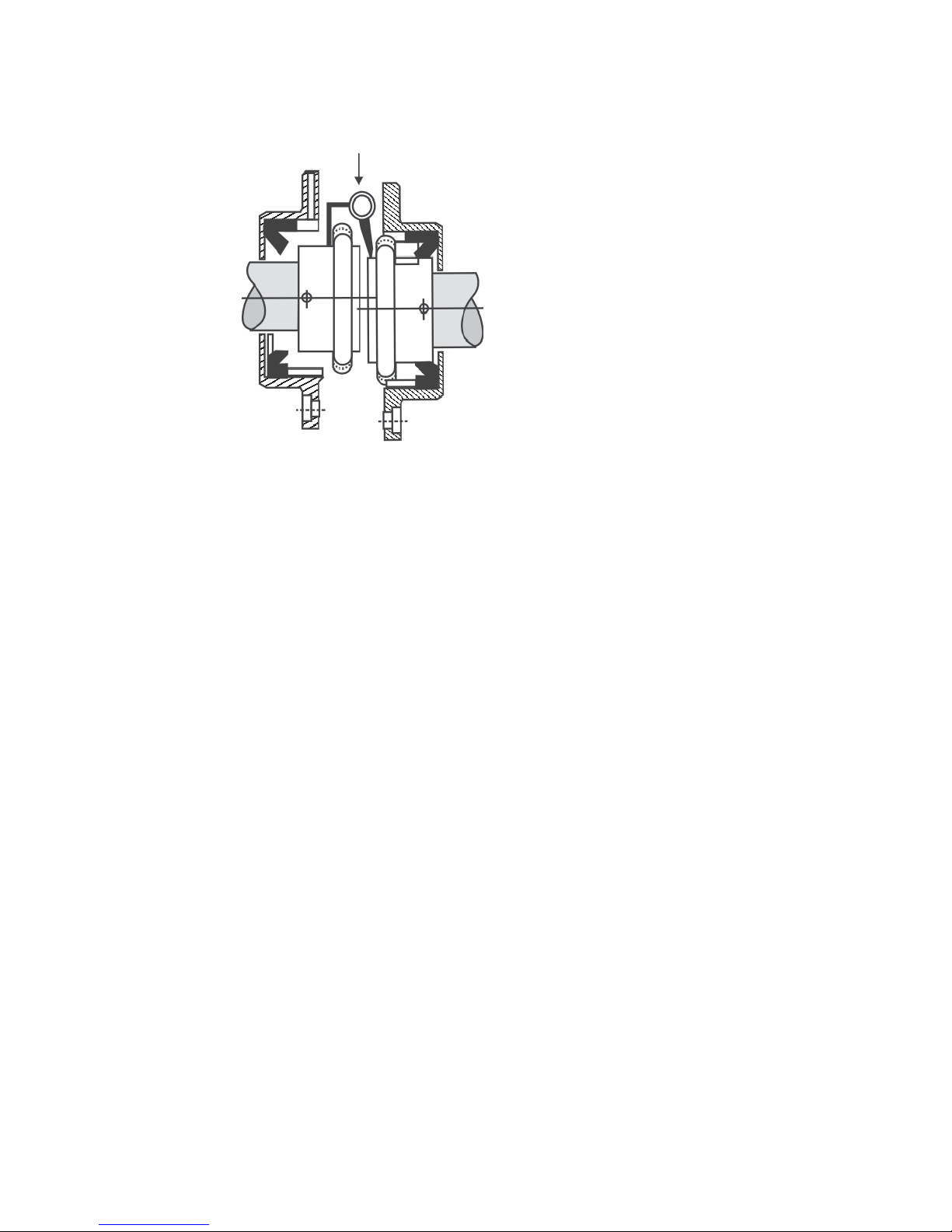
Single-bearing alignment
Before assembling the generator to the prime mover, remove the exciter
cover and adapter cover. Remove the blocking holding the drive discs to
the adapter. Also make sure the generator bearing end clearance is not
less than the total engine crankshaft axial movement plus 1/16 inch. The
generator is shipped from the factory with 1/8-inch minimum bearing
end clearance. (This dimension is recorded on the Factory Recorded
Dimensions sheet, packaged with the generator.)
Measure the distance from the end of the exciter shaft extension to the
bearing housing on the endbracket (dimension A in Figure 13). This
dimension is recorded on the Factory Recorded Dimensions sheet,
packaged with the generator. If the dimensions do not match, move the
rotor axially relative to the stator until the dimensions are equal.
Endbracket
Bearing
Exciter fi eld
A
Shaft extension
Figure 13: Generator coupling check
Check the engine fl ywheel housing pilots’s radial and face runout by
mounting a dial indicator and measuring the fl ywheel to the fl ywheel
housing as shown in Figure 5. See Table 1 for maximum allowable
runout.
Check the engine fl ywheel’s radial and face runout by mounting a dial
indicator and measuring the fl ywheel housing to the fl ywheel as shown
in Figure 3. See Table 2 for maximum allowable runout.
Copyright © 2012 Kato Engineering, Inc. All rights reserved
Measure the generator drive plate diameter (dimension S of Figure 14)
and fl ywheel bore diameter (dimension B of Figure 15). Drive plate
diameter must not be greater than the fl ywheel bore diameter. Also check
to make sure the hole centers match (dimension W of Figure 14 and
dimension C of Figure 15).
Page 18

Measure the axial distance from the surface on the generator adapter
to the outside surface on the drive disc coupling plates (dimension Y
in Figure 14). This dimension is recorded on the Factory Recorded
Dimensions sheet, which was packaged with the generator. If the
dimensions do not match, move the rotor axially relative to the stator
until the dimensions are equal.
Measure the axial distance from the machined surface on the engine
fl ywheel housing the bottom of the fl ywheel drive disc recess
(dimension G in Figure 15). Make sure the difference between
dimensions Y (of Figure 14) and G are less than 1/32 inch. If G is
more than Y, install additional spacers between the drive discs and the
generator hub. If Y is more than G, remove spacers between the drive
discs and generator hub.
Adaptor
Drive
plates
Y
Fan
WARNING: Never grind the OD
of drive discs or attempt to drill out the
holes. If the dive discs do not fi t properly ,
use different discs or a different fl ywheel.
The number and thickness of drive discs
are specifi ed for torque requirements. Do
not remove drive discs to compensate
for spacing Drive disc modifi cations may
result in drive disc failure and debris
ejected from the generator.
S
A
W
Bolt holes
Figure 14: Single bearing generator drive plate
and adaptor
Shaft
Page 19
Copyright © 2012 Kato Engineering, Inc. All rights reserved

Tapped
bolt holes
B
Flywheel
Figure 15: SAE fl ywheel and adapter
G
C
Install the generator to the engine. Make sure the drive discs seat in
the recess of the fl ywheel housing. Secure the generator to the engine
(drive discs to fl ywheel, adapter to fl ywheel housing), and the base. Use
lock washers on all bolts. Torque the adapter and drive discs in a crisscross pattern to the values in Table 3.
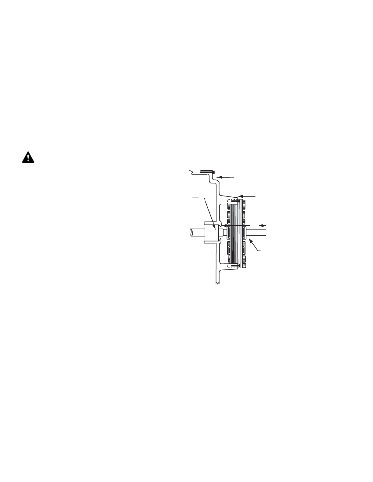
Ensure that the bolts in the fl ywheel do not bottom out. If they are too
long or cannot be tightened with a socket or box wrench, use 1/4 to 3/8inch long spacers inserted in the bolts as shown in Figure 16 to increase
the clearance between the bolt head and the fl ywheel.
Occasionally, there is insuffi cient clearance to install the bolts that
fasten the drive discs to the engine fl ywheel, and the fan will have to be
temporarily moved to accommodate this. This situation will typically
occur with several types of generators:
• With the three-frame units that have an aluminum fan, loosen the fan
hub bolts to move the fan. After installing the drive disc-to-fl ywheel
bolts, move the fan back so the rotor-side edge is fl ush with the air
opening and the minimum distance between the windings and the
fan is 3/8 inch. Torque the fan hub bolts to 75 ft-lbs.
Copyright © 2012 Kato Engineering, Inc. All rights reserved
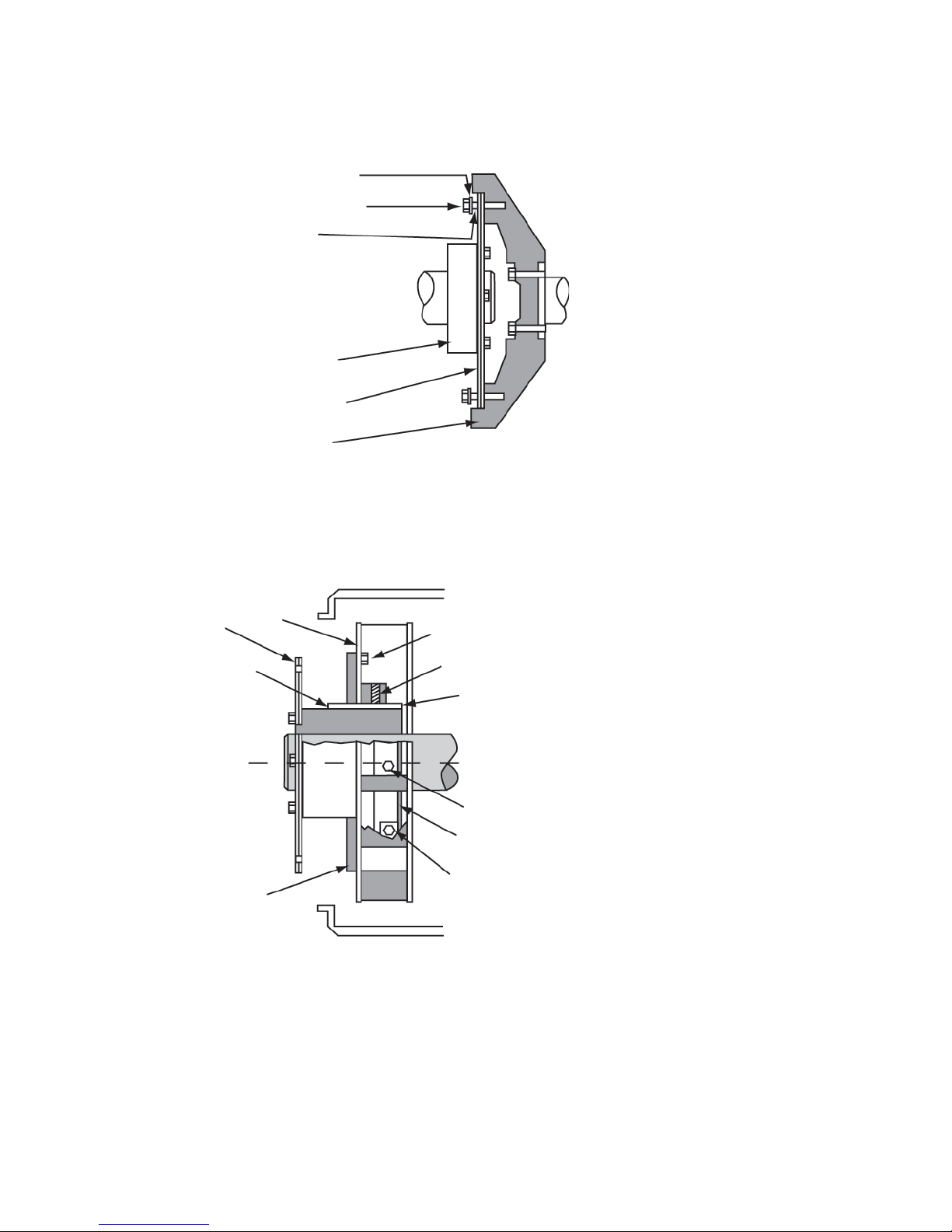
• With sheet metal fans with cast hubs that are in turn mounted on the
drive hub, mark the drive hub as closes as possible to the fan hub.
Loosen the two set screws, the fan clamping bolt, and the fan bolts.
Wedge the fan open, and move it out of the way (See Figure 17).
After attaching the drive discs-to-fl y wheel bolts, align the fan hub
to the mark to move the fan back to its original position. Ensure
the key is fully in place under the fan hub and positioned so the set
screw will press on the key. Tighten the fan hub clamping bolt and
the set screws. Install the fan bolts and torque them according to
Table 3.
Page 20
Drive discs
Keyway
Lock washer
Bolt
Spacer
Drive hub
Drive plates
Flywheel
Figure 16: Disc-to-fl ywheel installation
Fan
Fan bolts
Set screw
Key
IMPORTANT: The generator with sheet
metal fans and cast fan hubs is shipped
from the factory with the fan 1/2 to 3/4 inch
from the fan baffl e and clear of the inside
adaptor for optimum air fl ow through the
exhaust screen.
Fan hub
Figure 17: Moving sheet metal fans
Bolt holes
Alignment mark on
drive hub
Fan hub bolt
Copyright © 2012 Kato Engineering, Inc. All rights reserved
Page 21

After installing the drive disc-to-fl ywheel bolts, check the runout of the
generator shaft by placing the base of a dial indicator on the generator
frame and positioning of the probe on the shaft as shown in Figure 18.
If the total indicated runout exceeds 0.003 inch, remove the drive discs
bolts, and rotate the generator relative to the engine fl ywheel. Reinstall
the bolts, and check the runout again.
Recheck the shaft-end-to-bearing-housing distance (dimension A in
Figure 13).
Mount the brushless exciter armature assembly to the generator shaft
(as described in the assembly procedures below).
Adapter
Fan
Dial indicator pointer
Shaft
Copyright © 2012 Kato Engineering, Inc. All rights reserved
Drive plates
Drive hub
Figure 18 Runout check
Page 22

Foot defl ection
After alignment, check for foot defl ection or “soft foot” condition on
each shim location to eliminate distortion of the generator frame. Do
this by loosing one mounting bolt at a time and checking defl ection
after retightening. Defl ection at the shim location from shims under
compression to a loosened condition must not exceed 0.003 inch.
Doweling
In case the mounting bolts loosen during operation, doweling will
prevent movement of the generator. Dowel as follows:
Check the alignment after the generator has been in operation for at least
48 hours. If alignment is not satisfactory, realign.
Drill holes through the footpads and into the base in two mounting pads
opposite each other. Drill the holes slightly smaller than the dowel pin.
Ream the holes to the proper diameter for the pin. Clean out chips, and
install the pins.
Electrical connections
If the generator was subjected to a rapid change in temperature, freezing
or wet conditions during shipment or storage, measure the insulation
resistance of each winding and dry the generator, if necessary, as
described in the maintenance section below.
Make all electrical connections (main load, temperature monitoring
device, space heater, AVR) in accordance with local regulations and
national/international electrical code requirements. Check the electrical
diagrams provided with the generator or manual. The main terminals
need to be properly spaced for the load connections. Refer to Table 3 for
the proper torque values for the connections.
NOTICE: Alternator current machines are
intended for continuous operation with
the neutral at or near ground potential.
Operation with one line at ground potential
should be done only for infrequent periods
of short duration, for example, as required
for normal fault clearance.
On larger generators grounding points are provided for properly
grounding the system to the generator frame. The grounding wire must
be sized to national/international code requirements.
Space heaters
When the generator has optional space heaters to prevent water
condensation during long periods of downtime, connect the space heaters
so they start when the generator is turned off and stop when the generator
is switched on. Some generators with space heaters have thermostats.
The thermostat should be set above the dewpoint. Refer to the electrical
diagrams for the space heater characteristics.
CAUTION: The space heaters
are designed to be energized when the
generator is shut down. They are hot
enough to cause skin burns. Terminals for
power at the space heaters are live during
operation. Disconnect power to the space
heaters before removing the generator
covers.
Copyright © 2012 Kato Engineering, Inc. All rights reserved
Page 23

WARNING: Do not pry on the
generator fan blades. Blades can weaken
which could result in serious injury or death
from fl ying debris.
Inspection before startup
After electrical connections have been made, perform the following
checks:
• Check all the connections to the electrical diagrams provided.
• Secure all covers and guards.
• Turn the rotor slowly with the appropriate starting mechanism (bar
the engine or fl ywheel) through one revolution to see if the rotor
turns freely.
NOTICE: For specifi c lubrication
instructions, always refer to the bearing
lubrication sheet that came with your
manual or the lube plate on the generator.
Unauthorized lubricants may result in a
bearing failure
• Check the bearings to see they are properly lubricated.
• Determine the direction of the engine rotation, and make sure that it
matches the rotation of the generator.
• Make sure the power requirements comply with the data on the
generator nameplate.
• Make sure that the engine-generator set is protected with an adequate
engine governor and against excessive overspeed.
• Make sure the output of the generator is protected with an overload
protection device, such as circuit breakers or fuses, sized in
accordance with national/international electrical code and local
electrical code standards. Fuses need to be sized using the lowest
possible current rating above the full-load current rating (115% of
rated current is commonly recommended).
Remove tools and other items from the vicinity of the generator.
Copyright © 2012 Kato Engineering, Inc. All rights reserved
Page 24

Operation
Initial startup: generators with both automatic and
manual voltage control
1. Disconnect the generator output from the load by opening the main
circuit breaker.
2. Turn the manual voltage adjust rheostat fully counterclockwise.
3. Put the auto-manual switch in the manual position.
4. Start the prime mover, and bring the set to rated speed. Turn the
manual voltage adjust rheostat to reach rated voltage. Close the
output circuit breaker, and apply load in steps until the rated load is
reached. Adjust the manual adjust rheostat as necessary to obtain the
desired output voltage.
5. Gradually reduce load, and adjust the rheostat accordingly until no
load is reached. Open the circuit breaker, and stop the prime mover.
6. Actuate the auto voltage rheostat. Then start the genset, and bring it
to rated speed. Adjust the voltage to the desired value.
NOTICE: Do not actuate the auto-manual
switch with the full load applied to the
generator. Generator over voltage will
result which may cause damage to the
generator control and protection equipment.
Whenever possible, stop the generator
before switching to assure full load is not
applied.
7. Close the output circuit breaker. Then check the generator voltage
and voltage regulation. Apply load in steps until the rated load is
reached.
8. Check for vibration levels at no load and rated load. A slight increase
is normal. As the load is maintained for 2-3 hours, the vibration
levels will gradually increase and reach a fi nal level.
Initial startup: Generators with automatic voltage control
only (generator has an automatic voltage regulator (AVR)
with no auto-manual switch)
1. Disconnect the generator output from the load by opening the main
circuit breaker.
2. Turn the voltage adjust rheostat fully counterclockwise. Start the
prime mover, and bring the set to rated speed. Turn the voltage adjust
rheostat to obtain the desired voltage.
3. Close the output circuit breaker, and apply load in gradual steps
until the rated load is reach. Notice the voltage regulation with the
changes in load steps.
4. Check for vibration levels at no load and rated load. A slight increase
is normal. As the load is maintained for 2-3 hours, the vibration
levels will gradually increase and reach a fi nal level.
Page 25
Copyright © 2012 Kato Engineering, Inc. All rights reserved

Restoring residual magnetism/fi eld fl ashing
The direct current necessary to magnetize the revolving fi eld is obtained
from the exciter. Upon starting the generator, current and voltage is
induced into the exciter by the magnetic lines of force set up by residual
magnetism of the exciter fi eld poles. Residual magnetism of the exciter
fi eld poles may be lost or weakened by a momentary reversal of the fi eld
connection, a strong neutralizing magnetic fi eld from any source, or non-
operation for a long time. If the generator fails to generate voltage after
it has come up to rated speed, it may be necessary to restore residual
magnetism.
To restore the small amount of residual magnetism necessary to begin the
voltage build up, connect a 12 or 24-volt battery to the exciter fi eld coil
circuit and fl ash as follows:
1. Open the output circuit breaker, and stop the engine.
2. Disconnect the exciter fi eld coil wires EF1 at the terminal EF1 and
EF2 at the terminal EF2, and connect the battery positive lead to the
fi eld coil lead EF1.
3. Flash the fi eld by touching the battery lead to the fi eld coil circuit
terminal EF2.
4. Disconnect the battery leads.
5. Reconnect the fi eld coil lead EF1 to terminal EF1, and reconnect the
fi eld coil lead EF2 to terminal EF2.
6. Start the generator, and check for voltage build up. Refl ash if
the generator output voltage does not build up, or fl ash with the
generator running, the fi eld coil wires connected to the regulator, and
a 3-amp or larger diode off the positive terminal of the battery per
Figure 19.
-
12 or 24 V
battery
+
3 amp or
larger diode
FF+
Voltage
regulator
Copyright © 2012 Kato Engineering, Inc. All rights reserved
EF2
Figure 19: Field fl ashing setup with the fi eld wires
connected to the regulator
Page 26
EF1

Continuous operation
Operate the generator within the nameplate values . If the generator is
operated below the rated power factor and voltage, decrease the kVA to
prevent overheating of the fi eld and stator windings. Consult the factory
for derating factors if the application requires the unit to be operated
beyond nameplate values.
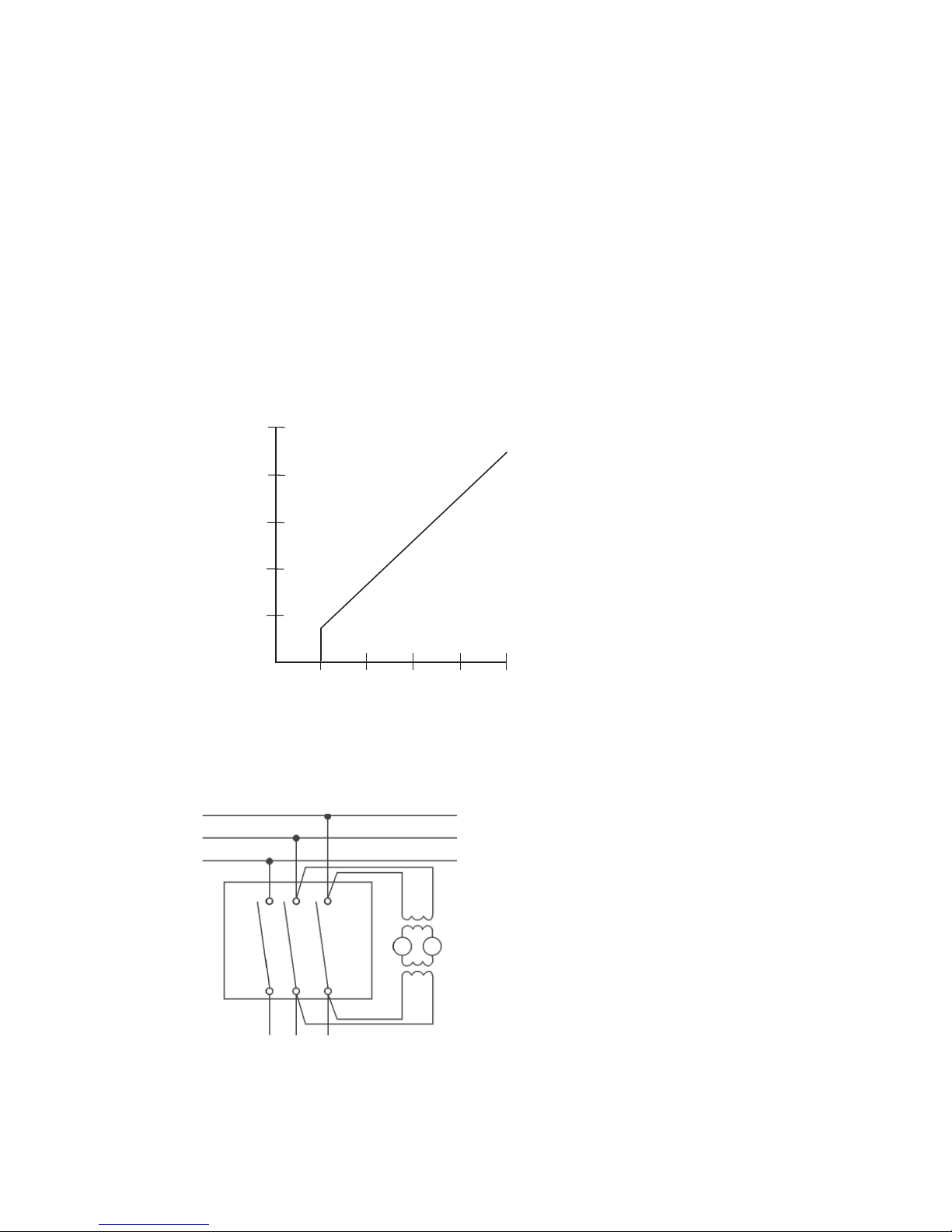
Rotor overheating may occur when the generator is carrying excessive
unbalanced loads. Negative sequence currents fl owing in the fi eld pole
face cause the rotor heating. For a general guide to the allowable phase
unbalance, see Figure 20, Guide to allowable phase unbalance (which is
based on a 10% equivalent negative sequence current).
The guide is used in the following manner: Find the point where the
vertical line (determined by the maximum current in any of the phases
and expressed in percent of rated current) crosses the horizontal line
(determined by the minimum current in any of the phases and expressed
in percent of rated current). Ensure the point where these two lines
intersect is within the permissible allowable unbalance region for safe
operation of the generator.
Loss of fi eld excitation can result in the unit operating out of
synchronization with the system when operating is parallel. This has the
effect of producing high currents in the rotor, which will cause damage
very quickly. Protective relays should be considered to open the circuit
breaker.
NOTICE: Operating the unit beyond name-
plate values may cause equipment damage
or failure.
Idling
Unless the voltage regulator has V/Hz protection built in, having the
generator set in operating mode while idling the engine can cause
permanent equipment damage. If engine adjustments require that
the engine be run at idle speed and the regulator does not have V/Hz
protection, make the generator regulating system inoperative during
idling by one of the following methods:
When the generator is provided with a voltage shutdown switch, be sure
the switch is set to the idle position while the engine is running at idle
speed.
Where the generator set is provided with fi eld circuit breakers, set the
circuit breaker to the off position while the generator is running at idle
speed.
Where the generator set is provided with an automatic/manual control
switch that has an off position, switch it to off while the engine is
running at idle speed.
Where the generator set does not have any of the above options, remove
the wires from the voltage regulator input power terminals when the
engine is running at less than rated speed.
Page 27
Copyright © 2012 Kato Engineering, Inc. All rights reserved

IMPORTANT: If the polarity of the exciter
is reversed by fl ashing the fi eld, it may be
corrected by interchanging the battery leads.
Parallel operation
For the generator to operate in parallel with a system in operation, the
phase sequence of the generator must be the same as that of the system.
Use transformers to reduce the voltage to an acceptable level, and then
use a phase rotation meter or incandescent lamp method, described in
electrical machinery handbooks, for a phase sequence check.
The output voltage at the paralleling point must be the same as each
instant, which requires that the two voltages be of the same frequency,
same magnitude, same rotation, and in coincidence with each other.
Voltmeters indicate whether the voltage magnitude is the same, and
frequency meters indicate whether the frequencies are the same. Whether
the voltages are in phase and exactly at the same frequency is indicated
by a synchroscope or by synchronizing lamps.
A synchroscope can be used to indicate the difference in phase angle
between the incoming machine and the system. The generator can be
paralleled by using incandescent lamps connected as shown in Figure 21.
The voltage rating of the series lamps must equal the voltage rating of the
transformer-low voltage winding.
WARNING: Shock hazard - Do
not make connections or otherwise make
contact with the generator leads or other
devices connected to them unless the
genset is stopped and the phase leads are
grounded. A rotating generator is always
producing some voltage and contact with
the leads or other devices connected may
result in serious injury or death
NOTICE: Refer to the voltage regulator
manual for complete details and possible
additional instructions. Damage to the rotating diodes, generator, and voltage regulator
can be caused if the regulator is operated
improperly.
Each prime mover in the system must have the same speed regulating
characteristics, and the governors must be adjusted to give the same
speed regulation as determined by applying load that is proportional to
the full load rating of the generator.
The voltage regulator must include paralleling circuitry. In addition, the
voltage, droop settings and the V/Hz regulation characteristics must be
the same for all the voltage regulators. This will allow the generators to
properly share reactive loads.
If cross-current compensation is used, paralleling current transformers
must give the same secondary current.
Current transformer secondary windings provide reactive kVA droop
signal to the voltage regulator. Accidental reversal of this electrical
wiring will cause the voltage to attempt to rise with load rather than
droop. If this occurs during paralleling, stop the unit and reverse the
wires at the voltage regulator terminals.
If the set is provided with a unit/parallel switch, set the switch to the
parallel position on the unit being synchronized.
Copyright © 2012 Kato Engineering, Inc. All rights reserved
Synchronize the generator by adjusting the speed (frequency) slightly
higher than the system. Observe the synchroscope or the lamps. The
lamps should fl uctuate from bright to dark at the rate of one cycle every
2 to 3 seconds. When the generator is in phase (the lights will be dark),
close the circuit breaker. Immediately after closing the breaker, measure
Page 28
the line current kVAR of the generator. The readings must be within
the rating of the unit. A high ammeter reading accompanied by a large
kW reading indicates faulty governor control. A high ammeter reading
accompanied by a large kVAR unbalance indicates problems with the
voltage regulator. Adjusting the cross current or voltage droop rheostat
should improve the sharing of kVAR.
To shut down the generator operating in parallel, gradually reduce the
kW load by using the governor to reduce speed. When kW load and
line current approach 0, open the generator circuit breaker. Operate
the generator unloaded for several minutes to dissipate the heat in the
windings. Refer to the prime mover manual for shutdown and cool-down
procedures.
100
80
Allowable
unbalance
60
Excessive
40
20
Min. current in any phase (% of rated)
020406080
Max. current in any phase (% of rated)
unbalance
Figure 20: Guide to allowable phase unbalance
System bus
Load
switch
100
Synchronizing
lamps
Load lines from the incoming generator
Figure 21: Synchronizing paralleled generators with test lamps
Page 29
Copyright © 2012 Kato Engineering, Inc. All rights reserved

Maintenance
Schedules
A regular preventive maintenance schedule will ensure peak
performance, minimize breakdowns and maximize generator life. The
schedule listed below is a guide for operating under standard conditions.
Specifi c operating conditions may require reduced or increased
maintenance intervals. Also, if there is a different or more specifi c
schedule for your generator than the schedule provided below, it will be
included as a supplement to the manual package.
Every day
Visually check generator bearing housings for any sign of oil seepage.
Check the operating temperatures of the generator stator windings.
Check the control panel voltmeter for proper stability and voltage output.
Monitor the power factor and generator loading during operation.
With generators that have sleeve oil bearings, check the operating
temperatures and sight glass levels (if applicable).
Every week
Visually inspect the bearing exterior for dirt, and clean if necessary.
Inspect any generator air fi lters for build up of contaminants, and clean or
replace as required
Every 2000 Hours or 6 months of operation
Remove generator outlet box cover. Visually inspect the stator output
leads and insulation for cracking or damage. Check all exposed electrical
connections for tightness. Check transformers, fuses, capacitors, and
lightning arrestors for loose mounting or physical damage. Check all lead
wires and electrical connections for proper clearance and spacing.
Clean the inside of the outlet box, air screens, bearing housings, and air
baffl es with compressed air and electrical solvent if needed.
Copyright © 2012 Kato Engineering, Inc. All rights reserved
Page 30

With generators that have ball or roller bearings, check machine
vibrations and bearing condition with a spectrum analyzer or shock
pulse.
Regrease the regreaseable-type bearings. With generators that have
sleeve oil bearings, inspect bearing oil for proper levels and clarity.
Every 8000 hours or 1 year of operation
Check insulation resistance to ground on all generator windings,
including the main rotating assembly, the main stator assembly, the
exciter fi eld and armature assemblies, and the optional PMG assembly.
Check the space heaters for proper operation.
Check the rotating rectifi er connection tightness.
With generators that have sleeve oil bearings, replace the bearing oil.
Every 20,000 hours or 3 years of operation
With generators that have sleeve oil bearings, perform a sleeve bearing
inspection to include the removal of the upper bearing housing and
bearing liner to inspect the liner, shaft journal, and seal surfaces for wear
or scoring.
Remove the endbrackets, and visually inspect the generator end windings
for oil or dirt contamination. Excessive contamination may necessitate
surface cleaning with compressed air and electrical solvent.
Inspect the fan and fan hub for damage.
Every 30,000 hours or 5 years of operation
(Contact Kato Engineering for assistance)
Disassemble generator.
Clean the generator windings using either (depending upon the severity
of contamination) 1) compressed air and electrical solvent or 2) degreaser and high pressure hot water wash. Dry the windings to acceptable
resistance levels (see the dry out procedure).
Inspect the rotor shaft bearing journals for wear or scoring.
With generators that have ball or roller bearings, replace the bearings.
With generators that have sleeve bearings, replace the bearing liners and
oil seals.
NOTICE: Rotor removal should be
performed only as necessary and based
on the level of contamination and / or a low
Insulation Resistance value.
Page 31
Copyright © 2012 Kato Engineering, Inc. All rights reserved

WARNING: Shock hazard - Do not
service the generator or other electrical
machinery without de-energizing and
tagging the circuits as out of service.
Dangerous voltages are present, which
could cause serious or fatal shock.
NOTICE: For specifi c lubrication
instructions, always refer to the bearing
lubrication sheet that came with your manual
or the lube plate on the generator.
Maintenance procedures
Visual inspection methods of windings
Electric machines and their insulation systems are subjected to
mechanical, electrical, thermal and environmental stresses that give rise
to many deteriorating infl uences. The most signifi cant of these are the
following:
Thermal aging: This is the normal service temperature deteriorating
infl uence on insulation.
Over temperature: This is the unusually high temperature of operation
caused by conditions such as overload, high ambient temperature,
restricted ventilation, foreign materials deposited on windings, and
winding faults.
Overvoltage: This is an abnormal voltage higher than the normal service
voltage, such as caused by switching or lightning surges or non-linear
loads. Operating above rated nameplate voltage will reduce insulation
life.
Contamination: This deteriorates electrical insulation by 1) conducting
current over insulated surfaces 2) by attacking the material to reduce
electrical insulation quality or physical strength, or by 3) thermally
insulating the material so the generator operates at higher than normal
temperatures. Such contaminants include water or extreme humidity, oil
or grease including unstable anti-wear and extreme pressure lubricants,
conducting and non-conducting dusts and particles, industrial chemicals
such as acids, solvents, and cleaning solutions.
Copyright © 2012 Kato Engineering, Inc. All rights reserved
Physical damage: This contributes to electrical insulation failure by
opening leakage paths through the insulation. Physical damages can be
caused by physical shock, vibration, over-speed, short-circuit forces or
line starting, out-of-phase paralleling, erosion by foreign matter, damage
by foreign objects and thermal cycling.
Ionization effects: Ionization (corona), which may occur at higher
operating voltages, is accompanied by several undesirable effects such as
chemical action, heating, and erosion.
To achieve maximum effectiveness, a direct visual inspection program
initially to those areas that are prone to damage or degradation caused
by the infl uences listed above. The most suspect areas for deterioration
or damage are 1) ground insulation, which is insulation intended to
isolate the current carrying components from the non-current bearing
components, and 2) support insulation, which includes blocks and slot
wedges and are usually made from compressed laminates of fi brous
materials, polyester, or similar felt pads impregnated with various types
of bonding agents. Check for the following:
Page 32

Deterioration or degradation of insulation from thermal aging:
Examination of coils reveal general puffi ness, swelling into ventilation
ducts, or a lack of fi rmness of the insulation, suggesting a loss of bond
with consequent separation of the insulation layers from themselves or
from the winding conductors or turns.
Abrasion: Abrasion or contamination from other sources, such as
chemicals and abrasive or conducting substances, may damage coil and
connection surfaces.
Cracking: Cracking or abrasion of insulation may result from prolonged
or abnormal mechanical stress. In stator windings, looseness of the
bracing structure is a certain sign of such phenomena and can itself cause
further mechanical or electrical damage if allowed to go unchecked.
Erosion: Foreign substances impinging against coil insulation surfaces
may cause erosion.
Cleaning
Exterior: Wipe loose dirt from the exterior with a clean, lint-free cloth.
Remove stubborn accumulations of dirt with a detergent or solvent
that won’t damage the paint or metal surfaces. Use a vacuum to clean
ventilating ports.
Windings, assembled machines: Where cleaning is required at the
installation site and complete disassembly of the machine is unnecessary
or not feasible, pick up dry dirt, dust or carbon with a vacuum cleaner to
prevent the redistribution of the contaminant. A small non-conducting
nozzle or tube connected to the vacuum cleaner may be required to reach
dusty surfaces or to enter into narrow openings. After most of the dust
has been removed, a small brush can be affi xed to the vacuum nozzle to
loosen and allow removal of dirt that is more fi rmly attached.
WARNING: When using cleaning
solvents, ensure adequate ventilation and
user protection. Inhaling vapors may impair
breathing and/or cause damage to internal
organs.
After the initial cleaning with a vacuum, compressed air may be used to
remove the remaining dust and dirt. Compressed air used for cleaning
must be clean and free of moisture or oil. Air pressure or velocity must
be adequately controlled to prevent mechanical damage to the insulation.
Disassembly of the machine and more effective cleaning by a qualifi ed
Kato technician may be required if the above described fi eld service
cleaning procedures do not yield effective results.
Windings, disassembled machines: Take an initial insulation resistance
reading on the machine to check electrical integrity. The high pressure
hot water wash method of cleaning, which sprays a high velocity jet of
hot water and water containing a mild detergent, is normally effective
in cleaning windings, including those subjected to fl ooding or salt
contamination.
Page 33
Copyright © 2012 Kato Engineering, Inc. All rights reserved

IMPORTANT: The insulation resistance
tests are usually made on all or parts
of an armature or fi eld circuit to ground.
They primarily indicate the degree of
contamination of the insulating surfaces
or solid insulation by moisture and other
conducting infl uences and will not usually
reveal complete or uncontaminated
ruptures.
IMPORTANT: The insulation resistance
value increases with de creasing winding
temperatures. All readings must be
corrected to winding temperatures. Use
Table 4 for converting megger readings to
other temperatures (e.g., 100 megohms at
50º C is converted to 170 megohms: 1.7 x
100).
Winding
Temp
(ºC)
10
20
30
40
50
60
70
80
90
100
110
120
Conversion
factor
0.23
0.37
0.6
1
1.7
2.7
4.5
7.5
14
23
38
61
Table 4: Temperature conversion
factor for resistance readings
NOTICE: Never apply the megger to the
rotating rectifi er, the voltage regulator, or
generator accessories (e.g., temperature
detectors, space heaters) These devices
can be damaged by the applied voltage.
IMPORTANT: New generators should
measure about 100 megohms minimum
of insulation resistance when meggered.
Generators that read 50 megohms or less
should be dried out according to the dry out
procedures here. Generators with insulation
resistance readings of 10 megohms or less
should be investigated.
Use multiple sprays with clean water to remove or dilute the detergent
following the detergent spray. Dry the machine until acceptable
insulation resistance values are obtained at room
temperature. See the insulation resistance procedures below for minimum
recommended values.
Electrical contacts: Clean electrical contacts, switch contacts and
terminals with an approved contact cleaner. Do not fi le contacts.
Insulation resistance tests at low voltage
Insulation tests are conducted for two reasons: to discern existing
weakness or faults or to give some indication of expected service
reliability. Insulation resistance tests are based on determining the current
through the insulation and across the surface when a DC voltage is
applied. The leakage current is dependent upon the voltage and time of
application, the area and thickness of the insulation, and the temperature
and humidity conditions during the test.
Refer to the following electrical measurement procedures for testing
detail. Contact Kato Engineering or refer to IEEE Standard. 432-1992
when more extensive insulation tests are required
When checking insulation resistance with a megger, fi rst verify the
ground path. Connect one test lead to a ground point. Then connect
the second test lead to another ground location to prove the ground
connection. Once the ground path has been proven, the second test lead
can be connected to the leads of the component to be tested.
Exciter fi eld (stator) and PMG armature (stator)
1. Disconnect the exciter leads from the terminals in the ter minal box or
the voltage regulator.
2. Connect exciter leads to one clamp of 500-volt megger, and connect
the other clamp to the exciter fi eld frame.
3. Apply 500 V from the megger, and measure the resistance reading
after 1 minute. The reading must be a minimum of 50 megohm. If it
is not, refer to the cleaning or dry out procedures.
4. Ground the exciter fi eld leads to the exciter fi eld frame for several
minutes after the megger has been disconnected. This will allow the
voltage build up to be properly discharged.
5. Repeat steps 1-4 for the PMG armature (stator).
Copyright © 2012 Kato Engineering, Inc. All rights reserved
Page 34

Exciter armature
1. Disconnect the exciter armature leads from the rotating rec tifi ers.
2. Connect the leads of the exciter armature to one clamp of a 500-volt
megger, and connect the other clamp to a suitable connection on
exciter sleeve or shaft.
3. Apply 500 V from the megger, and measure the resistance reading
after 1 minute. The reading must be a minimum of 50 megohms. If it
is not, refer to the cleaning or dry out procedures.
4. Ground the exciter leads to the exciter sleeve or shaft after
disconnecting the megger. This will allow the voltage build up to be
properly discharged.
Winding rated
voltage (V)
*
Insulation
resistance test
direct voltage
(V)
<1000 500
1000-2500 500-1000
2501-5000 1000-2500
5001-12000 2500-5000
>12000 5000-10000
Table 5
Guidelines for DC voltages to be
applied during insulation resistance
tests
Main rotor
1. Disconnect the generator fi eld leads from the posi tive and negative
terminals of the rotating rectifi er assembly.
2. Connect the positive and negative leads to one clamp of the megger,
and connect the other clamp to the shaft.
3. Apply voltage from the megger, and measure the resistance reading
after 1 minute. The reading must be a minimum of 50 megohms. If it
is not, refer to the cleaning or dry out procedures. (See Table 5).
4. Ground the fi eld leads to the shaft after disconnecting the megger for
a minimum of 1 minute. This will allow the voltage build up to be
properly discharged.
Main stator
1. Disconnect power connections and all control appara tus from the
generator terminals.
2. Measure insulation resistance of each phase separately with the two
other phases shorted to the frame.
*
Rated line-line voltage for three-phase
ac machines, and line-to-ground voltage
for single-phase machines, and rated
direct voltage for dc machines or fi eld
windings.
3. Use a megger connected between the lead(s) of the phase to be
measured and generator frame. The minimum 1-minute insulation
resistance must not be less than 50 megohms. (See Table 5).
4. Ground the leads to the frame after the 1-minute megger test. This
will allow the voltage build up to be properly discharged.
Page 35
Copyright © 2012 Kato Engineering, Inc. All rights reserved

NOTICE: Do not apply heat too rapidly. It
could damage the windings.
Dry out procedures
If the insulation resistance readings are below the recommended minimum values specifi ed previously, use one of the dry out procedures
described below. Select the procedure based on the size and location
of the unit, available equipment, and experience of personnel. Before
drying, remove the voltage regulator, and cover all inlet and discharge
openings. Provide an opening at the top of the machine, preferably at the
fan end, for moisture to evaporate.
Drying with external heat: Place heat lamps, space heaters (in addition
to the ones already supplied) or a steam pipe near the windings. Monitor
winding temperatures. Raise winding temperature gradual ly at a rate
of 10-20° F (-12° to -6°
C) per hour up to 200° F (93° C). Measure
insulation resistance at 1-hour intervals. Typically the insulation
resistance will slowly drop while the temperature is coming up, and then
gradual ly increase and level out.
Drying with AC current in the armature: Short circuit the generator
terminals. Provide DC excitation to the brushless exciter fi eld winding.
Insert a current transformer and an ammeter to read full load current.
Run the generator at rated speed. Apply excitation to the exciter fi eld
until rated current is developed. Monitor winding temperatures until they
stabilize. Continue running until insulation resistance values level off.
Monitor winding temperatures. Raise winding temperature gradually at a
rate of 10-20° F (-12° to -6°
C) per hour up to 200° F (93° C). Measure
insulation resistance at 1-hour intervals. Typically, the insulation
resistance will slowly drop while the temperature is coming up and then
gradually increase and level out.
NOTICE: For specifi c lubrication
instructions, always refer to the bearing
lubrication sheet that came with your manual
or the lube plate on the generator.
Copyright © 2012 Kato Engineering, Inc. All rights reserved
Bearing lubrication
Shielded or sealed ball bearings: Shielded or sealed ball bearings are
factory packed with lubricants and generally can be operated several
years without requiring replenishment or change of the grease. If
repacking the grease is necessary, disassemble the machine, clean the
bearings, and repack the bearings about 1/2 full using a high quality ball
bearing grease, which must be capable of lubricating satisfactorily over a
temperature range of the lowest ambient temperature to 250º F (121
o
C).
Regreaseable ball or roller bearings: In applications where regreaseable
bearings are used, grease fi ll fi ttings and relief valves are incorporated
into the bearing housing. Lubricate the bearings in accordance with the
lubricating instructions attached to the generator.
Sleeve bearings: Lubricate the bearings in accordance with the
lubricating instructions attached to the generator and the bearing
lubrication instructions, which are provided in the manual package as
supplementary material.
Page 36

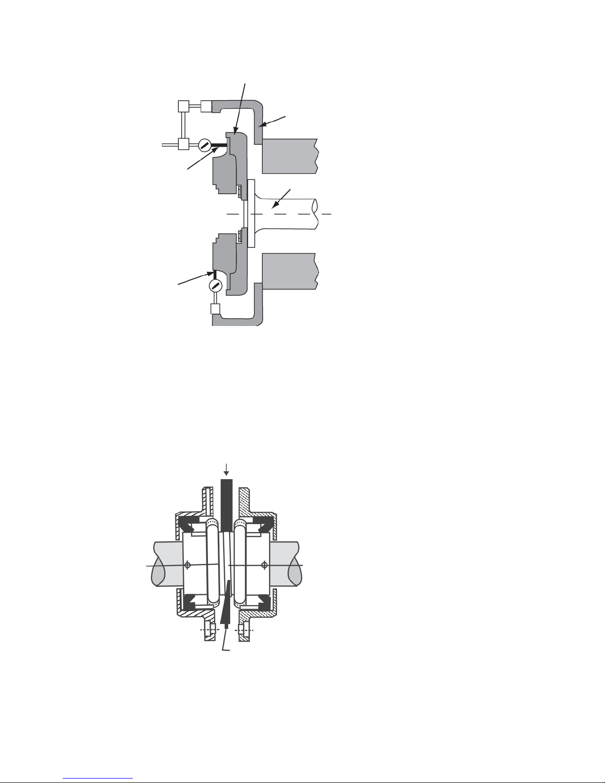
Rectifi er tests
If a failure of a rectifi er is suspected, remove the exciter cover. Remove
the nut and washer holding the rectifi er in the heat sink, and remove the
diode lead wire. Lift the rectifi er from the heat sink (see fi gure 22 for
an overview). Test the entire rectifi er with an ohmmeter or test lamp as
follows:
Negative
Positive
Positive
Figure 22: Rectifi er
Ohmmeter: Connect the ohmmeter leads across the rectifi er in one
direction (see Figure 23). Notice the meter reading. Reverse the leads,
and Notice the meter reading. The meter should indicate a low resistance
when the leads are across the rectifi er in one direction and a high
resistance when the leads are across the rectifi er in the opposite direction.
A low resistance in both directions indicates a short. A high resistance in
both directions indicates an open rectifi er.
Reverse
diode
Standard
diode
Figure 23: Testing the rotating rectifi er with an
Cathode
Ohmmeter
Anode
ohmmeter
Copyright © 2012 Kato Engineering, Inc. All rights reserved
Page 37

Test lamp: Connect the leads of a test lamp, consisting of standard
fl ashlight batteries and a fl ashlight and built, as shown in Figure 24,
across the rectifi er in one direction. Then reverse the leads. The light
should light in one direction but not the other. If the light lights in both
directions, the rectifi er is shorted. If the light does not light in either
direction, the rectifi er is open.
Figure 24 Test lamp
Replace defective rectifi ers with rectifi ers of the same operating
characteristics as rectifi ers installed in the generator at the factory. Order
rectifi ers by part number, including the model and type of exciter as well
as the generator serial number.
Surge protectors may be included on the rotating rectifi er assembly.
Disconnect one lead of the surge protector, and connect the leads of an
ohmeter or makeshift test lamp, consisting of standard fl ashlight batteries
and a fl ashlight and built as shown in Figure 24, across the surge
protector in either direction.. If the light comes on, the surge protector
is defective. Order surge protectors by part number, including the model
and type of exciter as well as the generator serial number. Following
replacement, make sure that the revolving fi eld, exciter armature, and
rotating diode leads are properly secured.
Copyright © 2012 Kato Engineering, Inc. All rights reserved
Page 38
Disassembly
Overall disassembly
1. Remove the terminal box cover, and disconnect the load leads and
all other leads. Tag the leads to ensure they are correctly connected
when the generator is reassembled.
2. Remove the bolts securing the generator to the base and prime
mover, and move the generator to an area that allows suffi cient room
for disassembly.
IMPORTANT: The following procedures are
meant to be a general guide. Procedures for
your unit may vary.
WARNING: Ensure the generator
has stopped and is de-energized before
disassembly. A rotating generator is always
producing some voltage and contact with
the leads or other devices connected may
result in serious injury or death
3. Remove the coupling or drive plates.
4. Remove the exciter cover.
5. Remove the clips securing the exciter fi eld leads to the exciter frame
and endbracket. Disconnect the leads and remove the exciter frame/
stator and/or exciter-PMG frame/stator.
6. Remove the (optional) PMG and exciter armature as described
below.
7. Support the shaft. Remove the exciter-end endbracket bolts, and
remove the endbracket. Tap lightly with a rubber or fi ber mallet
to loosen the endbracket if necessary. Repeat with the drive-end
endbracket (if applicable).
8. Remove the fan from the hub where applicable. If necessary, make
sure to mark the location of the fan for reinstallation.
9. Float out the rotor (see Figure 25). First attach a pipe over the shaft
on the drive end. Attach slings around the pipe on one end and
around the shaft on the opposite end. Lift up the rotor, and move it
out, resting the rotor as the slings are moved down the pipe for the
next lifting stage.
WARNING: Use a hoist and slings
or chains to support components during
removal. Use lifting devices that are
selected for generator component weights.
Improper lifting techniques may cause
serious injury or death. Be extremely
careful not to damage components.
NOTICE: Ensure the generator fi eld wires
are fl at in the wireway so they don’t tear
during pulling. Do not pull on the edges of
the heat sinks or on the exciter armature
windings.
NOTICE: Make sure the pipe is strong
enough to support the weight of the rotor
and that it does not have rough edges on
the inside, which could damage the shaft.
NOTICE: To prevent tension on the shaft,
put the slings around the largest shaft step
possible.
NOTICE: Make sure the rotor does not
rest on the stator during the stages of
movement. Make sure the rotor does not hit
the stator.
Copyright © 2012 Kato Engineering, Inc. All rights reserved
Page 39
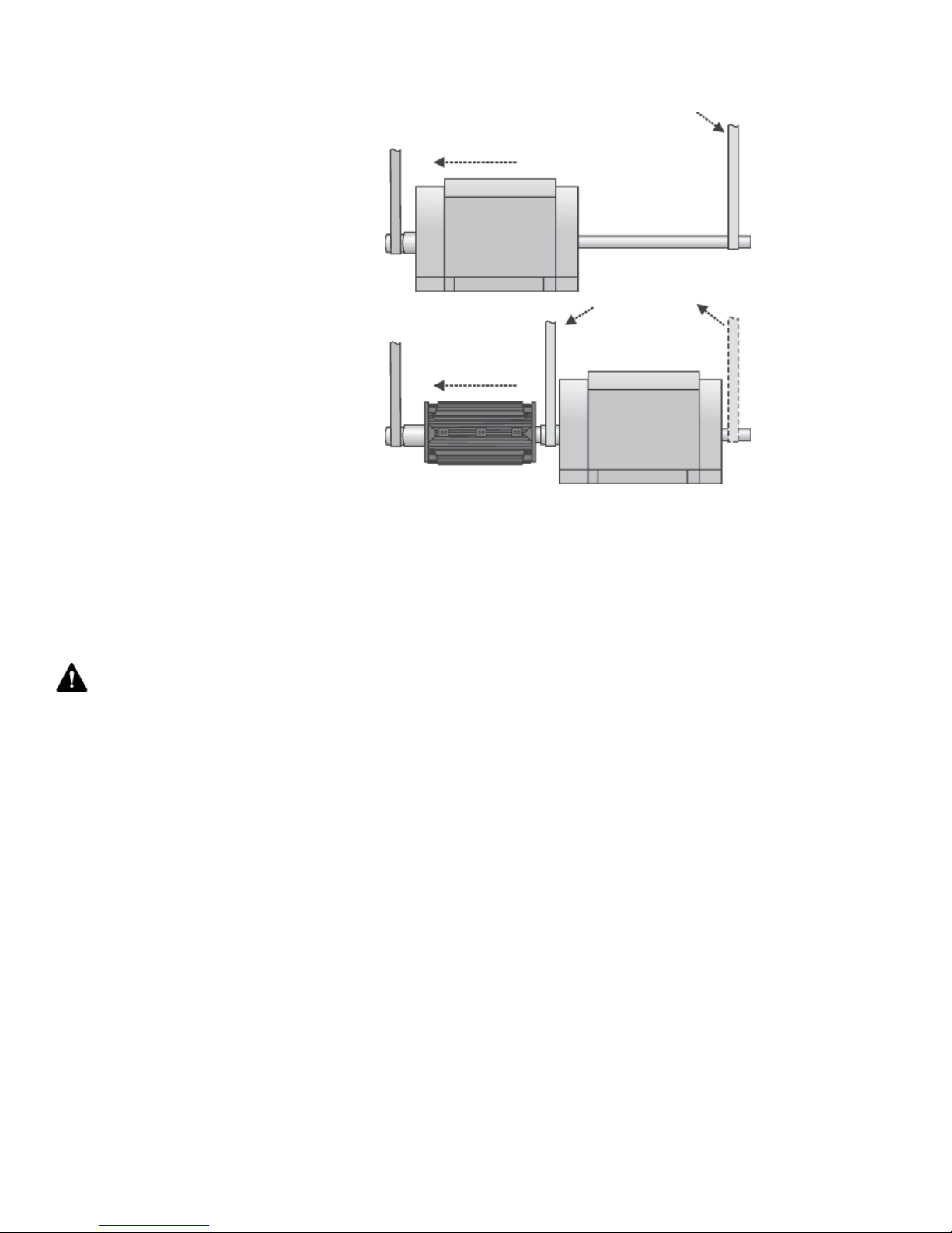
Figure 25: Floating the rotor
Exciter armature and PMG removal (see Figure 26)
1. Remove the exciter cover.
2. Remove the retaining bolt and washer.
3. Disconnect the fi eld wires on the rotating rectifi er assembly.
WARNING: Strong Magnetic fi elds
- Pull the PMG off straightly. The assembly
may pull toward other steel components.
Be careful that your fi ngers or hands do
not get pinched. Stay clear if you have any
medically implanted devices, the strong
magnetic fi elds may cause medical device
failure resulting in death.
NOTICE: Ensure the generator fi eld wires
are fl at in the wireway so they don’t tear
during pulling. Do not pull on the edges of
the heat sinks or on the exciter armature
windings.
4. If the generator has a PMG rotor, pull it off separately using hand
force. Wrap the PMG rotor in plastic to avoid contamination with
metal fi lings. Notice: Some inboard PMG assemblies use a locknut to
secure the PMG rotor. See fi gure 28. To remove the PMG rotor with
a lock nut:
a) On the lockwasher, pry up the tab that is bent down in a notch of
the locknut. Then unscrew the locknut with a spanner wrench, and
remove the lockwasher.
b) Pull the PMG rotor straight back. Take care not to cock the PMA
when pulling it off.
c) Wrap the PMG rotor in plastic to avoid contamination with metal
fi lings.
5. Slowly pull the armature assembly off of the generator shaft. If the
exciter can not be pulled off by hand, use a hydraulic jack as shown
in Figure 27.
6. Remove the key from the keyway in the generator shaft.
Copyright © 2012 Kato Engineering, Inc. All rights reserved
Page 40

PMG aligning
Retaining
washer
Retaining
bolts
PMG
pin
Hole in sleeve for fi eld
wires (some models
may have a slot)
Rectifi er
Retaining
bolt hole
A
B
Field leads
Wire slot
PMG
rotor
aligning
slot
Exciter arma-
ture
sleeve
Figure 26: Exciter armature assembly
Hydraulic jack
Exciter sleeve
Threaded rod
A
Exciter arma-
ture
Plate
Figure 27: Pulling the armature assembly
B
A-A end view of
exciter
Key
Keyway
Key
Shoulder
B-B cutaway view
of shaft
Wire slot
Bolt holes
Shoulder
Keyway
Locknut
Figure 28: PMG rotor with locking nut
Lock washer and tab
Copyright © 2012 Kato Engineering, Inc. All rights reserved
Page 41

Bearing removal
1. Remove the endbracket(s) to expose the bearing(s).
2. Use a puller to remove the bearing from the shaft end with a cap. If
the bearing is going to be used again, make sure the puller supplies
pressure only against the bearing inner ring (see Figure 29).
Puller against
bearing
Outer ring
Cap to protect shaft end
Inner ring
Figure 29: Bearing removal
Copyright © 2012 Kato Engineering, Inc. All rights reserved
Page 42

Assembly
Bearing installation (done prior to installing the rotor)
1. Heat the bearing to 220º F (104o C) - 250º F (121o C) in a clean oven
or with an induction heater.
2. Start the heated bearing on the shaft. Then use a fi ber or soft metal
tube to tap the bearing into place.
3. Ensuring that pressure is applied only to the bearing inner ring,
press the bearing onto the shaft until the inner ring seats against the
bearing shoulder on the shaft. Assemble the rest of the generator after
the bearing has cooled.
Overall assembly
1. Float in the rotor until the rotor and stator laminations line up.
Position the rotor such that a full pole face is at the bottom.
NOTICE: Make sure all components are
clean before assembly.
NOTICE: Torque fasteners to the values
specifi ed in Table 3 unless otherwise speci-
fi ed.
2. Install the endbrackets. Support the rotor during installation. Put an
corrosion inhibitor on the bare mating surfaces to prevent rust.
3. Install the exciter armature and optional PMG as described below.
4. Install the covers.
5. Install the coupling or drive plates.
6. Reconnect the load leads and exciter leads.
Exciter armature and PMG installation (see Figure 26)
1. Clean the shaft and inside of the exciter sleeve.
2. Place the key in the slot in the shaft.
3. Lay the generator fi eld wires fl at in the wireway with the wire ends
protruding past the end of the shaft.
4. Position the exciter armature assembly in line with the shaft, and turn
the assembly to the position where the keyway in the exciter sleeve is
in line with the key in the generator shaft.
NOTICE: Do not pound on the rectifi er or
armature windings. Component damage
may result.
5. With hand force, push the exciter armature assembly over the shaft,
so the end of the sleeve is against the shoulder on the shaft. When
it is part of the way onto the shaft, start the fi eld lead wires through
the wire hole or slot in the exciter sleeve. It may be necessary to tap
lightly on the exciter sleeve in order to move the assembly over the
key. Use a fi ber or rubber mallet. If installation is still a problem, use
a heat gun to expand the exciter sleeve.
Page 43
Copyright © 2012 Kato Engineering, Inc. All rights reserved

IMPORTANT:
IMPORTANT: To measure air gap, measure
completely around the gap between the
exciter armature and exciter fi eld with a
feeler gauge. Keep the gauge at the tightest
point, and turn the generator over to measure the air gap as the rotor turns.
6. Connect the exciter armature wires to the rectifi er terminals.
7. If the generator has a PMG, place it onto the end of the exciter
sleeve. Make sure it is aligned with the pin slot in the end of the
exciter sleeve.
8. Install the retaining washer and bolt, and torque (60 ft-lbs for a 1/2inch diameter bolt; 200 ft-lbs for a 3/4-inch diameter bolt).
9. Install the exciter frame/stator and/or exciter-PMG frame/stator.
Install the clips securing the exciter fi eld leads to the exciter frame
and endbracket and connect the leads.
10. Measure the air gap between the exciter armature and exciter fi eld
and between the PMG rotor and PMG stator. If the air gap of the
armature is less than specifi ed in Table 5 or if the air gap of the PMG
is less than 0.020 inch, check 1) generator-engine alignment, 2)
check for bearing wear, 3) check for misalignment of the armature,
PMG or stator.
WARNING: Do not pry on the generator fan blades. Blades can weaken which
could result in serious injury or death from
fl ying debris
11. Install the exciter cover.
Exciter armature
diameter (in.)
5 3/4
9 7/8
12 1/2
16 1/4
Table 5: Exciter air gap
Minimum air gap
(in.)
0.014
0.014
0.018
0.035
Copyright © 2012 Kato Engineering, Inc. All rights reserved
Page 44

Storage
If the generator is not installed in its operating location as soon as
received, store it in a clean, dry area, not subject to vibrations or sudden
temperature or humidity changes. Make sure the storage area temperature
is between 10º F (-12
less than 60%. If possible, storage should be in an ambient temperature
of approximately normal room temperature. Protect the shaft from
corrosion by applying an anti-corrosion agent. Cover the unit with a
durable cover.
Prepare units that cannot be stored in a temperature and humidity
controlled area as follows:
Install desiccant bags in the exciter cover and inside the end bells.
Vacuum seal the unit in a covering of plastic or other material designed
for that purpose.
Adequately tag the generator to ensure that preservative greases and
desiccant bags are removed before the unit is placed in operation.
If space heaters are supplied, energize them to keep condensation from
the windings.
o
C) and 120º F (49o C) and the relative humidity is
NOTICE: Grease used in ball and roller
bearing generators is subject to deterioration
over time. Before placing the unit into
service after long-term storage, check the
bearings for corrosion, and replace the
grease. Deteriorated grease can cause
bearing failure.
For storage longer than 2 months, rotate the shaft a minimum of 10
revolutions every 60 days.
When the unit is taken out of storage, check the insulation resistance on
all windings. (See the maintenance section).
Page 45
Copyright © 2012 Kato Engineering, Inc. All rights reserved

ASTM and SAE Torque Values
Grade 5
* Inch-pounds
GASKETED COVERS
Foot-PoundFoot-Pound Newton-Meter Newton-Meter
SCREW
SIZE
#4-40
Grade 2
Foot-Pounds Newton-Meter Newton-MeterFoot-Pound
Ft-Lbs Tol N-M Tol Ft-Lbs Tol N-M Tol Ft-Lbs Tol N-M Tol Ft-Lbs Tol N-M Tol
4 *
0.4
Grade 5 Grade 8
#6-32 8 * 0.9
#8-32 14 * 1.6
#10-24 20 * 2.3
#10-32 23 * 2.6
1/4-20 41618211
3 5172102143
5/16-18 8 2 11 2 17 3 24 4 10 2 14 3 25 5 34 7
3/8-16 15 3 20 4 31 6 42 8 12 2 16 3 40 10 54 14
7/16-14 24 5 32 6 50 10 65 13 70 15 95 20
1/2-13 36 7 50 10 75 ** 15 100 20 24 5 32 6 100 20 135 27
9/16-12 55 10 75 14 110 20 150 25 150 30 200 40
5/8-11 75 12 100 17 150 25 200 20 200 40 275 55
3/4-10 130 25 175 24 260 50 350 70 370 50 500 70
7/8-9 145 20 195 28 425 60 575 80 600 60 800 80
1.0-8 190 22 250 30 650 75 875 100 900 90 1200 120
1 1/8-7 265 27 350 35 790 80 1075 100 1200 120 1650 160
1 1/4-7 375 40 500 55 1100 120 1500 150 1750 180 2400 250
1 3/8-6 490 50 650 70 1450 150 1950 200 2300 230 3100 300
1 1/2-6 625 60 850 90 1750 180 2350 250 3000 300 4000 400
*
SCREW
SIZE
Brass Screws Grade B Top Lock NutsSet Screws
Foot-Pound Foot-PoundNewton-MeterFoot-Pounds Newton-Meter
Ft-Lbs Tol N-M Tol Ft-Lbs Tol N-M Tol Ft-Lbs Tol N-M Tol Ft-Lbs Tol N-M Tol
Stainless Screws
Foot-PoundNewton-Meter
Newton-Meter
#4-40 4 * 0.4 5 * 0.6
#6-32 8 * 0.9 10 * 1.1
#8-32 20 * 2.3 16 * 1.8 21 * 2.4
#10-24 18 * 2 24 * 2.7
#10-32 34 * 3.8 33 * 2.9 33 * 3.7
1/4-20 61925
1 7 2 61826181
5/16-18 13 2 18 3 9 2 12 2 11 2 15 3 11 2 15 3
3/8-16 23 2 31 6 16 3 22 4 21 4 28 5 18 2 24 3
7/16-14 36 5.14 50 10 26 5 35 7 33 7 45 9 28 4 38 5
1/2-13 50 10 70 14 35 7 45 9 45 9 60 12 44 ** 66012
9/16-12 55 10 70 13 60 11 80 15
5/8-11 110 18 145 24 85 14 115 19 100 17 140 23
3/4-10 180 35 240 46 120
23 160 31 130 25 180 35
7/8-9 430 60 580 82 205 30 280 40
1.0-8 580 70 790 90 300 35 400 45
1 1/8-7 430 45 590 60
1 1/4-7 550 60 750 80
1 3/8-6 700 70 950 100
1 1/2-6 930 100 1250 130
* Inch-pounds
Copyright © 2012 Kato Engineering, Inc. All rights reserved
Page 46

Metric Torque Values
SCREW
SIZE
Grade 4.8 to 6.8
Foot-Pounds Newton-Meter
Ft-Lbs Tol N-M Tol Ft-LbsTol N-M Tol Ft-Lbs Tol N-M Tol Ft-Lbs Tol N-M Tol
Grade 6.9 to 8.8
Newton-MeterFoot-Pound
Grade 8.8
Grade 10.9
Foot-PoundFoot-Pound Newton-Meter Newton-Meter
M4 x .70 1.1 1.5 2 2.7 2.9
M5 x .80 2.3 3.1 4 5.3 6
M6 x 1.00 4
1 5.2 1 7 1 9.3 2 4151102143
M7 X 1.00 6.5 1 8.7 2 11 1 15 3 16 5 34 7
M8 x 1.25 10 2 13 3 18 2 24 5 11 2 15 4 25 10 54 14
M10 x 1.50 20 4 27 5 32 4 43 9 13 3 18 4 47 15 95 20
M12 x 1.75 34 7 45 9 58 7 77 15 19 4 26 5 83 20 135 27
M14 x 2.00 54 10 72 13 94 10 125 23 132 30 200 40
M16 x 2.00 80 13 108 18 144 13 192 32 196 40 275 55
M18 x 2.50 114 22 152 29 190 22 253 50 269 50 500 70
M20 x 2.50 162 23 216 30 260 23 347 50 366 60 800 80
M22 x 2.50 202 23 269 31 368 23 491 55 520 90 1200 120
M24 x 3.00 245 25 327 33 470 25 627 65 664 120 1650 160
M27 x 3.00 360 40 480 52 707 40 943 100 996 180 2400 250
M30 x 3.50 500 50 667 70 967 50 1289 130 1357 230 3100 300
Grade 2
Grade 5
ASTM & SAE grade markings
Class 8.8
Metric grade markings
1-NM = 0.737 ft-lbs. = 8.85 in-lbs.
Page 47
Grade 8
Class 10.9
Copyright © 2012 Kato Engineering, Inc. All rights reserved
WARNING: Problems left uncorrected
may result in injury or serious damage,
which can result in costly repairs and
downtime.
Troubleshooting Guide
(corrective maintenance)
Between regular preventive maintenance inspections, be alert for any
signs of trouble. Correct any trouble immediately. See Table 6 for
symptoms, causes and remedies.
Symptom Cause Remedy
No Voltage Open voltage regulator, circuit breaker or
fuses
Overvoltage, undervoltage, or overload
devices tripped (when protective devices
are incorporated into the circuit)
Open circuit in exciter fi eld Check continuity of shunt fi eld and leads
Loss of residual magnetism in exciter
fi eld poles
Open circuit in stator windings Check for continuity in the windings. Return the
Malfunction of automatic voltage
regulator
Short-circuited generator output leads Clear lead to restore voltage buildup.
Open in rotating rectifi ers Check rotating rectifi ers, and replace if
Open in generator fi eld Check for continuity and return rotor to
Shorted or grounded surge protector Check for shorts or grounds. Replace .
Shorted or grounded rotating rectifi er Check for shorts grounds. Replace or repair.
Shorted or grounded exciter armature Check for shorts or grounds. Replace or repair.
Low voltage Shorted leads between the exciter armature
and generator fi eld
Incorrect stator connections Check the connections, and reconnect
Check. Reset the circuit breaker or replace
fuses if open.
Check for the cause of the abnormal condition.
Correct any defi ciencies. Reset devices.
Check the generator nameplate for nominal
operating values.
to voltage control. (Use ohmmeter or
wheatstone bridge) If open in fi eld coils,
remove exciter fi eld assembly and return
assembly to factory for repair.
Restore residual magnetism or fl ash fi eld. When
the voltage regulator is a model that requires
fl ashing, install an automatic fi eld fl ashing
system.
generator to the factory for repair if open.
See troubleshooting of voltage regulator.
Correct defi ciencies.
open.
factory for repair if fi eld coils are open.
Test and repair.
Copyright © 2012 Kato Engineering, Inc. All rights reserved
Table 6: Troubleshooting
Page 48

Symptom Cause Remedy
Low voltage
(cont.)
Improper adjustment of voltage adjust
rheostat
Adjust rheostat.
Excessive load Reduce load. With three-wire, single-phase and
four-wire, three-phase generators, the load on
each leg must be as evenly balanced as possible
and must not exceed the rated current on any leg.
Line loss Increase the size of the line wire.
High resistance connections (hot) Make better connections.
Shorted main or exciter fi eld Test the fi eld coils for possible short by
checking resistance with an ohmmeter or
resistance bridge. Return the rotor assembly
to the factory for repair if fi eld coils are shorted.
Low power factor Reduce inductive (motor) load. Some AC
motors draw approximately the same
current regardless of load. Do not use
motors of larger horsepower rating than
is necessary to carry the mechanical
load.
Weak fi eld due to operating in a warm
temperature
Improve the ventilation of the generator.
Field current can be increased providing
the generator temperature rating
stamped on the nameplate is not
exceeded.
Defective rectifi ers in rectifi er assembly
(stationary)
Check rectifi er assembly. Replace
defective fuses or rectifi ers.
Excessive load Reduce load to rated value.
Defective bearing Replace the bearing.
Improper speed of engine driven
Check and correct defi ciencies.
generator set due to defective governor,
ignition system, or carburetor
Voltage regulator not operating properly Check the regulator. Adjust, repair or replace.
Fluctuating
voltage
Prime mover speed fl uctuating Check frequency and voltage of incoming
power when the generator set is motor
driven. Check engine governor on
engine-driven generator sets.
Loose internal or load connections Tighten all connections.
Generator overloaded Reduce load to rated value.
DC excitation voltage fl uctuating Trace DC excitation circuit. Correct any
defects.
Overspeed Correct speed of prime mover.
Voltage regulator not operating properly Check the regulator. Adjust, repair or replace.
High voltage Improper adjustment of voltage adjust
Adjust rheostat and/or voltage regulator.
rheostat or voltage regulator
Voltage regulator not operating properly Check the regulator. Adjust, repair or replace.
Page 49
Copyright © 2012 Kato Engineering, Inc. All rights reserved

Symptom Cause Remedy
Overheating Clogged ventilating screens and air
Clean all screens and air passages.
passages
Dry or defective bearings Replace defective bearings.
Coupling misaligned Align the generator set.
Generator fi eld coils shorted or
grounded
Test fi eld coils for shorts. Replace
shorted rotor or return it to the factory for
repair.
Unbalanced load or overload, low PF Adjust load to nameplate rating.
Vibrations Defective or dry bearings Replace defective bearings.
Misalignment of generator and prime
Align the generator set.
mover
Generator not properly mounted Check mounting. Correct defective
mounting.
Transfer of vibration from another
source
Isolate the generator set from the source of
vibration by installing vibration dampeners
between generator set base and foundation.
Copyright © 2012 Kato Engineering, Inc. All rights reserved
Page 50

List of equipment required for installation and maintenance:
Test equipment Notices
Ammeter Clamp-on, 0 to 500 amp range for measuring of electrical cur rent.
Multimeter Digital, for measuring voltage, current, frequency and resistance.
Thermometer For measuring temperature in Celsius
Megger To measure insulation resistance.
Resistive Bridge To measure resistance of windings.
Special tools
Bearing puller For changing bearing.
Exciter puller For pulling exciter armature
Standard tools
Cable tool Crimping
Flashlight As required
Grease gun For lubricating bearings
Hammer Soft-faced
Lamp (incandescent) Safety light
Screwdrivers Standard, sized as required
Screwdrivers Phillips, sized as required
Wrench Adjustable, 12-inch
Wrench Torque 0 to 100 ft-lb
Wrench set Allen, 1/8 to 1/2 inch
Wrench set Socket, 1/4 to 1 Inch with 3/8 and 1/2 inch drive
Wrench set Standard, open-end/box-end combination sized 1/4 to 1 inch
Vacuum Electric with nonmetallic nozzle
Materials
Air Compressed, dry.
Corrosion inhibitor Nox-Rust VC #10 Oil or equivalent
Covering material Waterproof desiccant bags for protection from
moisture during long-term equipment storage
Detergent As required for cleaning
Gloves Chemical-protective
Gloves Electrical-protective
Heaters Space Heater, for eliminating excess moisture in damp areas and dry
out of motor or generator windings
Plastic Protection for long-term storage
Rags As required for cleaning
Water Warm and clean, for cleaning
Tags Warning and cautions
Page 51
Copyright © 2012 Kato Engineering, Inc. All rights reserved
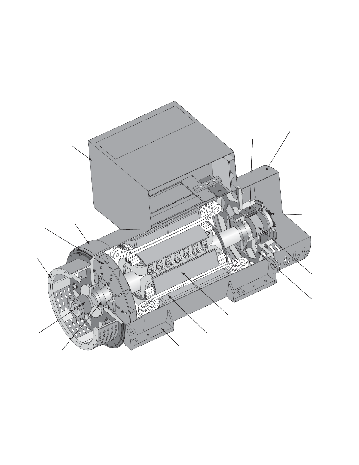
Lead connection
bo
x
Drip proof
Fan
cove
Main part location
r
Adapter
Coupling
hub
Rotor
Stator windings
Feet
Bearing
Copyright © 2012 Kato Engineering, Inc. All rights reserved
Page 52
 Loading...