

Page 1
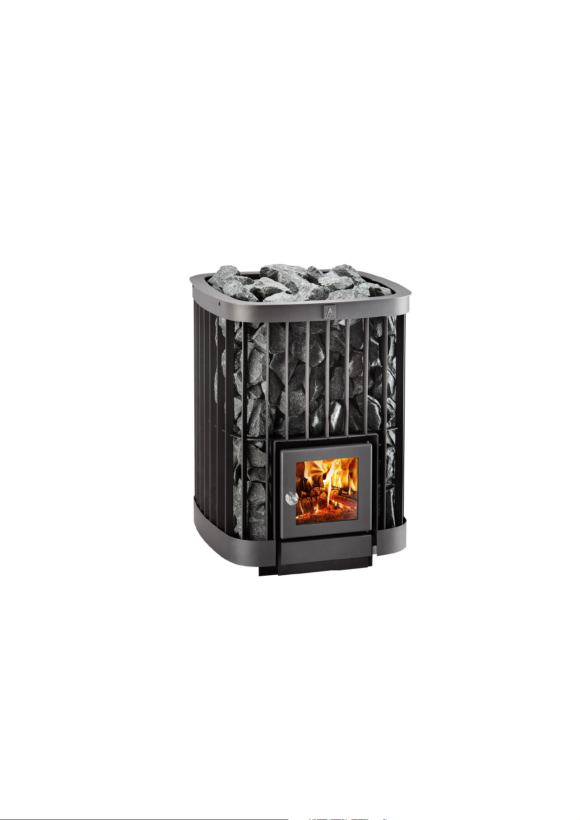
SAGA 20
SAGA 20
Page 2

SAGA 20
installation and usage manual
Please save these instructions for later use!
Once the installation is done, this manual should be given to the sauna’s owner or the
person in charge of running it.
Please read these instructions prior to installation and first use!
Inspect both product and the contents of the package as soon as you receive them. Report any
transport damages to the deliverer.
1.1. Package contents and its inspection
The stove package contains:
• Stove
• Within the fire compartment
o Installation instructions
o Grate
o Connection pipe
o 2 adjustment legs
o Door handle and attachment screws
o Air guide plate.
1.2. Important matters and regulations
During installation and use these instructions and all relevant official regulations must be
followed. The sauna stove must not be used for any other purposes such as drying clothes,
heavy heating during building etc. The stove must also never be covered in any way during use
or when it is warm.
Also check the following aspects and their influence on your choice of stove installation location:
o Safety distances to flammable and non-flammable structures (Chapter 2.3. and
2.4.)
o Location of chimney connection (height from floor of any existing chimney
connection or installation route of any new chimney pipe)
o Floor material (flammable, non-flammable, tiled and waterproofed)
2. Installation and preparation for use
2.1. Preparing for use and burn-in
• Install door handle according to chapter 2.7.
• Place the stove outdoors on a non-flammable base without stones.
• Remove any decals and protective plastic sheeting.
• Check that the grate and the air guide plate (picture 2) are in place.
• Install the connection pipe delivered with the package into the flue opening on top of the
sauna stove.
• Burn-in: The purpose of the burn-in is to remove out of doors any flammable protective
coating substances and to harden the stove’s coating. Burn a few full loads of wood in the
25 / 51
Page 3

fire compartment. Continue the burn-in until there are no more fumes rising from the
stove.
• Once the stove has cooled down after the burn-in, move it into the sauna.
• See to it that the sauna is well ventilated during the first couple of heating.
• Side panels can be loosened from the mantle if necessary, they are fastened with bolts at
the top and bottom.
2.2. Stones and their arrangement
Use peridotite or dunite or darkish natural stones with diameters of over 10 cm. always wash the
stones before installing them. They must not be stacked too tight or heaped up – arrange them
so that plenty of air can pass between them to warm the upper stones, as well. The maximum
stone capacity is about Saga 20 150 kg.
Cover the sides of the fire compartment fully with stones so that the safety distance to the side
remains at the minimum.
For the stove’s proper functioning it is essential that the hot air circulates between the stones to
heat them quickly. If the stones are too small or improperly arranged, you will heat the sauna
instead of the stones!
2.3. Stove base
The stove must be installed horizontally, on a stable and unmoveable non-flammable or fireproofed base.
The stove's legs are equipped with adjustment screws, with which it can be straightened
horizontally on an inclined surface. The adjustable legs are in the equipment bag in the stove’s
fire compartment. Screw them into place and adjust as needed.
Fireproofing of the floor on flammable material:
400 mm in front of the stove
250 mm to the sides
250 mm behind the stove
(Or, at the sides and back up to a fireproofed wall; picture 2.3.).
2.3.1. Installation on wooden floor
On a wooden floor we recommend installation on a 60 mm thick, smoothly cast concrete slab,
which rises towards the back, with risers to provide a ventilation slit between it and the floor. The
stove is then straightened by adjusting the legs.
ATTENTION! Always check the carrying capacity of the wooden floor, as the loaded stove weighs more
than 250 kg.
2.3.2. Installation on tiled and waterproof floor
It is not recommended to install the stove directly on a tiled floor because among other things moisture
barriers and plate glues may contain substances vulnerable to warmth. Use for example the abovementioned concrete slab.
2.4. Safety distances and protections
2.4.1. Safety distances
ATTENTION! Since this is a stove with a flue outlet on the top, the central factor in determining
safety distances is the distance required by the connection pipe and flue channel.
Safety distances for the non-insulated connection pipe are 1000mm in all direction and 1200mm
above it.
This makes the stove's own safety distances irrelevant. See Picture 2.4.1.
These safety distances can be reduced by installing insulation according to chapter 2.4.2.
26 / 51
Page 4

Safety distances for the insulated flue channel are between 50mm and 150mm with the stove's
safety distances being the essential factors here.
For stone walls, the stove's safety distance is 50mm from the stove's outer surfaces, but
preferably 100mm to ensure sufficient air circulation.
The stove's safety distance to flammable material is 250mm to the side, at the back 500mm from
the stove’s outer surfaces. A safety distance of 1000mm should be left for in front of the stove
due to heat radiation and to allow room for work and maintenance. The absolute minimum is
500mm, but then you must ensure that the nearest panel in front of the stove does not exceed a
temperature of 85oC during test heating.
When the distance from the stove upper surface is at least 1200mm, the ceiling does not require
protection.
2.4.2. Reduction of safety distances
The required safety distances at the back and sides can be reduced by 50% using a single layer
of protection and by 75% with a doubled layer. The protection can be either a 1 mm thick metal
sheet or 7 mm of fibre-reinforced cement board (not gypsum board coated with paper or similar).
(Picture 2.4.1.) Safety distance is measured from the stove to flammable material.
A ventilation space of 30 mm must be left between wall and protector. The protector must be
detached from floor and ceiling (likewise between the plates for doubled protectors). If the sauna
has a flammable floor in front of the stove, the area to be protected extends 250mm beyond the
door’s sides and a minimum of 400 mm in front of it. In this case, the protection must be at least
a 1 mm thick metal sheet.
If the stove is installed with one side and the back against a brick wall, safety distances of 50 mm
to the side and 50 mm at the back are sufficient. Recommendation 100mm to ensure air
circulation.
The safety distances around a non-insulated connection pipe can be reduced in a similar
manner. The flue pipe’s insulated part within the sauna must always extend to 400 mm below the
ceiling.
In the case of the insulated part of the pipe the stove's safety distances are the determining
factor, which means that they can be reduced with insulation according to Picture 2.4.2.
For chimneys, the minimum safety distances to flammable material differs from product to
product. Always check the manufacturer’s instructions. In case of doubt, approach your local fire
safety officials.
2.5. Connecting the stove to a brick chimney
The stove can be connected to a brick chimney from the top and from behind. For a brick
chimney connection, the safety distances and protectors named in chapter 2.4. and the
chimney’s masonry regulations must be adhered to.
2.5.1 Stoves Saga JK and KSIL with extended feed doors
Stoves with extended feed doors must only be installed into walls made of non-flammable
material (brick, concrete etc.).The non-flammable material must be arranged around the door
extension as shown in picture 5. If there is a flammable floor in the room with the door, the area
27 / 51
Page 5

requiring protection must extend 100mm beyond both sides of the door and at least 400mm in
front of it. The protective layer should be a metal sheet with a thickness of at least 1mm.
2.5.1 Stoves with an extended door
The floors of the sauna and the room into which the stove door opens must be on an equal level.
The room with the stove door may also be on a lower level, but never higher than the sauna's
floor!
The stove and its extension must be installed on a sturdy, immovable, fireproof, level
surface. A cast concrete base is the best choice.
By adding fireproofing the stove and its door extension may also be installed on wooden
floors. Nevertheless, the dividing wall must be non-flammable (brick, concrete or similar). For the
sauna and the extended door, a concrete slab with a thickness of 60mm is usually acceptable
(remember to take care of moisture draining). The fireproofing on the sauna side floor must
extend 250mm in front of the stove, 250mm at its sides and 250mm behind it or, at the back and
sides, up to a fireproofed wall. The fire protection measures on the door side must also adhere to
the instructions in chapter 2.3.
In unclear cases consult the local fire safety officials.
2.5.2. INSTALLATION THROUGH THE WALL AND FITTING THE FRAME , JK
See also the instructions in chapter 2.6. concerning flue pipe installation.
Make sure that you have received the frame that belongs to the door extension.
Installation through the wall:
• Make a hole in the wall. Its size should leave about 10-20mm of clear space all around
the door extension. (290x450mm), normal door.
• Remove the stove door by taking the hinge pin off (note the 2 base plates between door
and frame). It is not always necessary to remove the door.
• Remove the ash door.
• On the other side of the frame, remove the rivet from its hole in the upper part.
• Install the stove from the sauna side.
• Insulate the gap between feed door and wall with fireproof mineral wool. Follow the
instructions of the mineral wool manufacturer!
• Install the frame into place via the door (do not yet attach it to the wall).
• Attach the door. Remember the base plates. At this point, you may choose the door's
opening direction.
• Place the rivet in the upper part of the frame in the remaining hole.
• Put the ash door into place.
• Ensure that a gap of 5-10mm remains between extended door and the frame on top of it
to allow for heat expansion.
• Attach the frame to the wall with six 5mm screws using metal attachments that are
embedded in the wall.
INSTALLATION THROUGH THE WALL AND FITTING THE FRAME, with KSIL door, JK
model
See also the instructions in chapter 2.6 concerning chimney installation.
Installation through the wall:
• Make a hole in the wall. Its size should leave about 10-20mm of clear space all around
the door extension. Width 445mm, height 555mm..
• Remove the door frame by pulling from the wall lead-through pipe.
• Push the stove to its place from the sauna side.
• Remove the covering frame. (if in place)
• Loosen the fastening screws of the frame (4 pcs) on both sides, they need not be
removed).
28 / 51
Page 6

• Remove the frame from the screws on the side by lifting upwards and pull after that forward away
from the screws.
• Push the extended door frame over the lead-through neck and also the ash compartment pipe, its
front edge goes into the slot in the front wall. Fasten in front with screws.
• Insulate the gap between the door extension and the wall with fireproof mineral wool.
Follow the instructions of the mineral wool manufacturer! Do not cover the air openings in
the upper edge of the frame with wool. They are situated right behind the upper edge of
the front frame.
•
Install the covering frame in place to its screws.
• Tighten the screws so that the lower edge of the covering frame is near the floor.
•
Push the door frame so that the covering frame goes well in its place against the wall and fasten
the door inside the
tunnel with two screws.
2.5.3. Connecting from the back Saga
JK and KSIL stoves cannot be connected from the back of the chimney; they only have a flue
opening.
Make an opening into the brick chimney that is 2–3 cm larger than the connection pipe. Remove
the plate covering the hole in the back mantle with a screwdriver. Put the cap covering the back
flue opening as the cap of the backmost hole on top of the stove. Put the connection pipe of the
stove into the back flue opening of the stove. Push the stove in place. Make sure that the
connection pipe goes well to the opening made in the chimney. Insulate
the connection pipe and the chimney with flexible, fireproof material such as stone wool
is tidied up with a Kastor covering plate, which is available at hardware stores. The covering plate is
fastened to the brick chimney with metal brackets or fireproof paste
.
the empty space between
. The
lead-through
2.5.4. Connecting from the top (all models)
In JK and KSIL models the connection opening is the one on the side of the door.
In normal models the connection opening is the one on the side of back wall.
Make an opening into the brick chimney that is 2–3 cm larger than the connection pipe.
Use a bent pipe for the connection from the top of the stove, which can be turned to align with the
chimney. Suitable bent pipes are available at the hardware store. Extend the bent pipe with an
extension piece, if necessary. Install the stove’s own connection pipe in the flue opening on top
of the stove. The bent pipe is then attached to the stove’s own connection pipe. Saw the bent
pipe and any extension pipe down to a suitable size where necessary. Make sure the pipe
extends sufficiently into the chimney (but not so far that it blocks up the chimney).
Seal the empty space between connection pipe and chimney with flexible, fireproof material such as stone
wool. The lead-through is then tidied up with a covering plate, which is available at your hardware store.
The covering plate is attached to the wall with metal bolts or fireproof paste.
2.6. Connecting to a Kastor or Helo chimney
In JK and KSIL models the connection opening is the one on the side of the door.
In normal models the connection opening is the one on the side of back wall.
Chimney sizes Saga 20 100mm and Saga 27 130mm
The stove can be connected from the top to a factory built Kastor chimney.
Make sure to choose the correct chimney type with regard to your stove mode, chimney height, exterior
circumstances, temperature class T 600 etc. For best results we recommend that you install a chimney
valve, as well.
• Install a non-insulated connection pipe and any necessary extension piping on top of the
connecting pipe. Where necessary, saw the connection pipe and the extension pipe down
to suitable size.
29 / 51
Page 7

• The chimney valve goes between the insulated and no insulated sections or into the first
insulated pipe section.
• Continue from the chimney valve with an insulated pipe. The insulated pipe section must
start at least 400 mm beneath the ceiling. Follow the chimney's installation and usage
instructions.
Remember to keep all safety distances to flammable and non-flammable materials named above.
Helo Oy does not guarantee the suitability and functioning of other manufacturers’ factory-built
chimneys with Helo and Kastor stoves. Helo Oy does not accept liability for the quality of other
manufacturers’ factory-built chimneys.
2.7. The stove door and changing the opening direction Saga and JK
The opening direction of KSIL doors cannot be changed.
The opening direction is changed by turning the door upside down.
The opening direction is changed by turning the door upside down.
• Open the door and push the hinge pin out of the lower hole.
• Pull the pin downwards out of the upper hole to release the door. Remember the
washers.
• Turn the door into the desired position.
• Slip the hinge pin first into the sleeve's upper hole and the washers on top of the sleeve
onto the pin. (The risers on the pin must be at the lower end.)
• Slip the door's upper hole onto the hinge pin above the sleeve.
• Finally, guide the hinge pin into the lower holes of the sleeve and the door.
2.9. General directions to prevent damage
When you bring the stove into the sauna, before you add the stones, burn a full load of wood in a
well ventilated sauna to burn off the last protective substances and harden the coating.
Please read and follow the instructions below:
• Remember to leave free air space to aid the burning process.
• Do not heat immediately at full blast, if it is cold. The brick chimney might suffer damage.
• Do not throw water directly at the glass door.
• The stove’s operating life shortens, if it is constantly heated to a red glow.
• The stove’s working life will be shortened significantly, if it is subjected to salt water. Note
that in close proximity to the sea even well water may contain salt.
• Factors influencing the stove’s useful life are, among other things, how well its size is suited to the
sauna, the fuel used, how often it is used, failure to follow these instructions and general
carefulness.
• Kastor stoves have been very carefully designed and tested. On the basis of our studies, we at
Helo Oy know that if the stove suffers damage in a very short time (e.g. the walls split or burn
through, the top burns through etc.), the stove has not been used according to instructions. Helo
Oy does not take responsibility for damage through failure to follow the user’s manual.
3. Using the stove
3.1. Fuel
Use only untreated wood in Kastor stoves, preferably sturdy split logs of various woods, such as birch or
alder. The logs should at most be 35 cm long. Wet or foul wood does not heat very well.
It is not permitted to burn treated wood, wood with nails, plywood, plastic, plastic coated
cardboard or paper in this stove. Fluid fuels may not be used even while starting the fire, since it
30 / 51
Page 8

might damage the grate. Do not burn full loads of very small wood such as shavings and
splinters, as they produce excessive heat for short durations.
The fuel logs must not be stored in the immediate vicinity of the stove. Remember the safety distances.
Only bring into the sauna as much wood as you can fit immediately into the fire compartment.
3.2. Adjusting the air flow
The stove has been designed to work best when the chimney’s air suction is about 10–20 Pa. If
the chimney is tall, this optimal air suction limit is easily exceeded. This excess can be noticed as
follows:
• The air flow cannot be adjusted with the ash door.
• The flames reach into the connecting pipe and even up to the chimney.
• The humming noise of the burn feels loud.
• Looking through the glass door, the flames rage with great strength towards the stove’s upper part.
• The sauna and/or stones do not heat up properly in 1,5 hours (although the stove has the correct
size).
When you light the fire, the chimney valve and ash compartment door must always be open.
Once the fire has taken hold and burns well, adjust the air flow with the ash compartment door.
Usually, depending on the draught, the ash door is kept open by about 0.5–2 cm.
The stove’s basic draught is just right, when the burning can be affected by the ash door and the
flames rise calmly. Then the stove has the cleanest burning and the best efficiency.
3.3. Adjusting the heat output
The heat output is affected by the quality and amount of fuel. Do not burn excessively long logs in the
stove. Take care not to heat the stove constantly to a red glow.
3.3.1. Lighting from below
• Place two smallish logs lengthwise in the fire compartment.
• Add some lighting aids between the logs and light them.
• Then place a few logs crosswise on the previous ones.
• Close the door and leave the ash compartment door open by about 3 cm.
Once these latest logs have burned some five minutes, straighten them into the grate direction
and fill the fire compartment lengthwise with solid split logs. Close the door and leave the ash
door open by 3 cm for a short while.
After this, slow down the burning by closing the ash door gap to 0.5–2 cm. During this heating
phase, the fire compartment walls should only heat up for a while to a red glow in their upper
parts. Usually, this will prepare the sauna for your bath in about 60 minutes. (Adding firewood
may be necessary due to big stone amount).
3.3.2. Lighting from above
Lighting from above is a departure from tradition. With this method, stove and stones heat up
slightly more slowly than with the usual way, but once you have found a good combination of
stove and chimney adjustments, the difference is not very big.
Lighting from above is more ecological, causes fewer emissions and raises more heat energy
from the firewood. As a result, you can bathe on less wood for a longer time.
• Check that the chimney valve is wide open.
• Use dry wood that has preferably been indoors for a day.
• Fill the fire compartment with firewood up to the door’s upper edge.
• Place ignition helpers on top, e.g. small sticks and a piece of bark.
31 / 51
Page 9

• Light the ignition helpers from the top.
• Close the door and leave the ash compartment door open by 3 cm.
• Once the fire has burned for 5–10 minutes, the burning can be adjusted by closing the
ash door to 0.5–2 cm. Restrict excessive draught with the chimney valve, if necessary.
Usually, this will prepare the sauna for your bath in about 60–70 minutes. (Adding firewood may
be necessary due to big stone amount)
3.3.3. Continuing the heating with a second load
Depending on how much you bathe, frost outside etc., you may need to continue the heating with several
loads.
Once the first load has turned to embers (in about 40–60 minutes, if the draught is right), place sturdy logs
lengthwise in the fire compartment. If you are not going into the sauna immediately after adding the wood,
leave the ash door gaping by a few millimetres. Now the fire should remain just right for a long time. When
you do go into the sauna, you can add a few logs, if necessary.
4. Maintenance
4.1. Cleaning the stove
The stove’s surface can be cleaned with a mild cleaning fluid detergent solution by wiping down
with a soft, moist rag.
The glass doors are cleaned with Kastor Noki Pois cleaning fluid, which is available in hardware
stores.
4.2. Ash removal
Excessive ash shortens the grate’s lifespan and weakens the burning. Remove the ash while it is cold,
always before the next heating, using a metal container to avoid a fire hazard.
4.3. Sweeping
The doors in the stone area of the stove are soot hatches (covered with a cap).
The inner parts of the stove are cleaned through the openings covered with a cap 2–6 times a
year, depending on the use.
If the stove has a chimney starting from the top, soot drops from the chimney to the stove from
where it must be removed.
4.4. Removal and cleaning of the stove's glass
The glass door must be treated with care. Do not slam it shut or uses it to push logs into the
stove. The glass doors are cleaned with Kastor’s Noki Pois cleaning fluid.
4.4.1. Changing a broken glass pane Saga and JK
• Remove the door according to chapter 2.7.
• Remove the glass splinters and the retainers.
• Straighten the tongues in the corners of the laths.
• Push the glass all the way into the upper lath and then into the lower one by adjusting the
glass. Centre it.
• Push the locking springs into the lath ends and bend the tongues against the glass.
• Attach the door to the stove.
4.4.2. Changing a broken glass pane KSIL (picture 1)
• Remove the glass splinters carefully.
• Remove the door from its hinges. Open and lift off from the hinge pins.
• Unscrew the nuts 1 and remove the glass fastener and base plates 2 and gaskets 3.
32 / 51
Page 10

• See to that the gaskets 4 are well over the frame (there will be no gasket in the upper
edge).
• Put the glass in place.
• Put the padding 3 where the glass fastener is.
• Put the glass fasteners and base plates in place and tighten the nuts vcarefully, not too
tight.
5. Troubleshooting
If the stove or the sauna fails to work as you think they should, go through the following check
list.
Smoke leaks into the sauna, bad draught.
Is the chimney valve open?
Is the connecting pipe attached tightly both to the stove and the chimney?
There mustn't be any air leaks.
Is the flame plate in the upper part of the stove clean of ash?
Is the connecting pipe between stove and chimney clear of ash?
Is the chimney fully open?
In need of sweeping, stuffed with snow, winter cap on etc.
Is the chimney intact?
Cracks, weathered
Is the draught height (chimney height) sufficient with regard to the environment?
Nearby trees, a steep hill etc. requires more than 3.5. metres as measured from the
chimney floor.
Is the chimney’s size correct?
At least a half brick wide or, depending on stove model, a round chimney of 115-130mm.
The stove stones do not heat up sufficiently.
Has the stove been fired sufficiently?
You should burn at least one compartment full of split, dry logs according to instructions.
Is there too much draught?
The flames reach into the connecting pipe, which is red hot, although the lower end of the
stove within the mantle is not red. See chapter 3.3. about draught adjustment and heat
output.
Is the draught too weak?
See chapter 3.2. about draught adjustment.
Correct amount of stones?
Are the stones packed too tight?
The stones need to be stacked in such a way that there is enough air between them. See
chapter 2.2. “Stones and their arrangement”.
Are the stones good quality and the correct size?
Suitable stones are peridotite or dunite of a length of over 10 cm and not too flat.
The sauna does not get hot enough.
Is the sauna new or the wooden structure otherwise moist?
For instance, a new log cabin sauna warms up properly past 80oC only after a year.
Is the stove properly heated?
Has the stove been fired sufficiently?
You should burn at least one compartment full of split, dry logs according to instructions.
Is there too much draught?
The flames reach into the connecting pipe, which is red hot, although the lower end of the
stove within the mantle is not red. See chapter 3.2. about draught adjustment and heat
output.
Is the draught too weak?
33 / 51
Page 11

See chapter 3.2. about draught adjustment.
Is the stove too big for the sauna?
Is the draught height (chimney height) sufficient with regard to the environment?
Nearby trees, a steep hill etc. requires more than 3.5. meters as measured from the
chimney floor.
Correct amount of stones?
The stones should reach up to the edge of the stone compartment at the edges and be
heaped up only by half a stone in the middle.
Are the stones packed too tight?
The stones need to be stacked in such a way that there is enough air between them. See
chapter 2.2.
Are the stones good quality and the correct size?
Suitable stones are peridotite or dunite of a length of over 10 cm and not too flat.
The sauna heats up quickly, but the stones remain cool.
Correct amount of stones?
Are the stones packed too tight?
The stones need to be stacked in such a way that there is enough air between them. See
chapter 2.2.
Is the stove too big for the sauna?
Keep the ventilation valve open to remove excess heat, which gives the stones time to
warm up as well. This will extend the heating period slightly.
Are you heating the sauna correctly?
Read chapter 3 of these instructions carefully.
Black flakes collect beneath the stove.
The stones may be weathered.
The flakes may be metal flaking off the stove. The stove has been heated too intensely at a red
heat.
The metal flakes off and the stove will break down prematurely.
There is a smell of sulphur in the sauna.
Traces of sulphur have remained on the stones from the quarry’s explosion or the stones
are naturally sulphurous.
6. Warranty and manufacturer identification
If the stove stands unused in a moist environment (such as a cold holiday cottage), it must be inspected for
any corrosion damage before use.
WARRANTY
Helo products are of high quality and reliable. For its wood burning stoves, Helo Oy grants a 1 year
warranty covering manufacturing flaws.
This warranty does not cover any damage incurred through incorrect use that does not accord with
instructions. See chapter 3 of this manual.
34 / 51
 Loading...