


Owners Manual
Robust-Aire®
Aquatic Aeration System
Contents
Important Safety Instructions . . . . . .pg2
Unit Specs . . . . . .pg2
Parts Included . . . . . .pg2
Installation Tools & Materials . . . . . .pg2
On Shore Preparation . . . . . .pg3
Diffuser Assembly Installation . . . . . .pg3
Compressor Connections . . . . . .pg4
No Cabinet System Installation Requirements . . . . . .pg5
Base Mount Cabinet Installation . . . . . .pg7
Post Mount Cabinet Installation . . . . . .pg7
Remote Manifold Accessory Installation . . . . . .pg7
Startup Procedure . . . . . .pg9
Winter Warning . . . . . .pg9
Maintenance . . . . . .pg9
Troubleshooting . . . . . .pg10
Warranty . . . . . .pg10
Kasco Marine, Inc.
800 Deere Rd.
Prescott, WI 54021
U.S.A.
PH 00+1+715+262+4488
FAX 00+1+715+262+4487
sales@kascomarine.com
www.kascomarine.com
Rev. 03/19/14

Important Safety Instructions
CAUTION
• Caution should be used when dealing with any
electrical equipment with moving parts.
• Extreme caution should be used around water,
especially cold water, such as in Spring, Fall,
and Winter, which poses a hazard in and of
itself.
• Running the system in freezing conditions may
create open areas of water in the ice at the
diffuser locations and also thin ice around the
area.
• Check your local laws and ordinances as some
areas require warning signs to be posted. The
owner will assume all risks with operating the
Robust-Aire System during winter months.
• Do not use waders in deep ponds/lakes or
ponds/lakes with drop-offs, drastic slopes, or
soft bottom material.
• Do not use boats that tip easily for installation,
such as a canoe, and follow all boating safety
rules and regulations, including wearing a PFD.
(Personal Flotation Device)
• Means for disconnection must be incorporated
inthexedwiringinaccordancewithlocaland
national wiring rules.
• Consultaqualiedelectricianforelectrical
installation.
Unit Specs
Model* Voltage # diffusers
RA1 120 1 1 3.6
RAH1 240 1 1 1.8
RA2 120 2 1 5.4
RAH2 240 2 1 3.0
RA3 120 3 1 5.4
RAH3 240 3 1 3.0
RA4 120 4 2 10.8
RAH4 240 4 2 6.0
RA5 120 5 2 10.8
RAH5 240 5 2 6.0
RA6 120 6 2 10.8
RAH6 240 6 2 6.0
*you may have a sufx at the end of your model. “NC”
stands for “no cabinet”. “PM” stands for “post-mount cabinet”. No sufx denotes the standard base-mount cabinet.
# compressors
Total amps
The specs should be used by your qualied electrician
to ensure properly sized circuits are installed. For all
RAH systems and systems RA1 - RA3, a dedicated 15
amp circuit is sufcient to supply power to the system.
For RA4 – RA6 systems, a dedicated 20 amp circuit is
recommended. For RA(H)4 – RA(H)6 systems (two
compressors and two fans), it may be useful to have
two dedicated 15 amps circuits available. This will
allow for one compressor/fan combination to continue
operating if the other compressor were to fail, be down
temporarily for maintenance or to allow sets to be run
intermittently during start-up to prevent a turn-over
(see start-up procedure for more info). Always consult
with a qualied electrician.
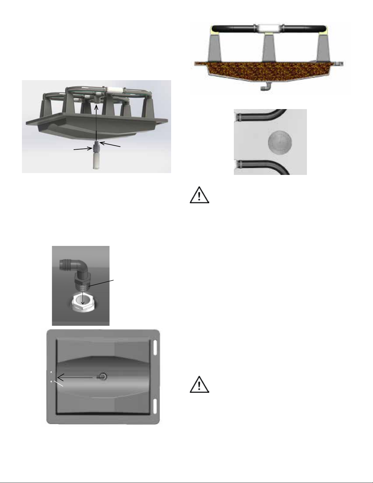
ROBUST-AIRE® DIFFUSER ASSEMBLY
Parts Included
• (1) Robust-Aire® Diffuser Assembly
• (1) Vent Plug
• (1) 3/8” Tubing Clamp
• (1) 5/8” Tubing Clamp
• (1) ½” NPT x 3/8” Barb Elbow
• (1) ½” NPT x 5/8” Barb Elbow
• (1) 3/8” Tubing Strain Relief
• (1) 5/8” Tubing Strain Relief
• (1) ¼”-20 x 1-3/8” Lg Hex Head Capscrew
• (2) ¼” Flat Washer
• (1) ¼”-20 Lock Nut
*Not all ttings will be used. Use 3/8” ttings with
3/8” SureSink ™ Aeration Tubing and 5/8” ttings
with 5/8” SureSink ™ Aeration Tubing.
Installation Tools & Materials
• 7/8” Open End Wrench or Pliers
• 20-30 lbs (.25-.375 cu.ft.) of pea gravel
• Length of ¼” – 3/8” nylon rope (or equivalent).
Rope length to be at least twice the water depth
• 7/16” socket wrench
• 7/16” box or open end wrench
• 5/16” Socket wrench or screwdriver
• PTFE thread sealant (teon tape)
2
On Shore Preparation
1. Apply PTFE Thread Sealant to male threads on check
valve. Slide check valve inlet assembly through diffuser base and into threaded port of the diffuser air
distribution assembly. Install hand tight only. Do not
overtighten.
4. Install vent plug once base is completely full.
Check valve
PTFE
Thread
Sealant
2. Install appropriate elbow tting into inlet port
located on the bottom side center of the diffuser
assembly. Install until hand tight. Continue
turning using 7/8” open end wrench until barbed
portion of the tting is pointing towards the edge
of the diffuser assembly with the strain relief
holes.
PTFE thread
sealant
Orientation of Fitting
CAUTION: Once the diffuser base has been
lled with gravel, do not lift assembly by diffuser hose
or PVC structure. Use outer edges of base to pick up
assembly.
If a boat is being used for diffuser placement, load the
boat with weighted diffuser assembly and remaining
parts kit. Do not use boats that tip easily for installation, such as a canoe.
Diffuser Assembly Installation
The effectiveness of the Robust-Aire® Diffuser is
greatly dependant on where the diffusers are located in
the pond. Therefore, proper placement is key. Space
the Robust-Aire® Diffusers equally from each other in
a depth that embodies the majority of the pond. Please
contact Kasco Marine if there are any questions on
placement.
Strain relief holes
3. Fill diffuser base with pea gravel to allow it to
ow easily into the base.
CAUTION: Do not use boats that tip easily for
installation, such as a canoe, and follow all boating safety
rules and regulations, including wearing a PFD. (Personal
Flotation Device)
5. It is recommended to place a buoy for each diffuser to
mark the area that it is to be placed.
6. Unroll the SureSink™ Aeration Tubing on shore to
remove any twists or knots. The performance will
3
decrease if the tube is not properly uncoiled.
7. On the end of the SureSink™ Tube that will be con-
nected to the diffuser assembly, slide a clamp over the
tubing and connect the end of the tubing to the barbed
tting on the diffuser assembly. Position clamp over
tubing and barbed tting and tighten using a 5/16”
socket driver or screwdriver. Do not over tighten
clamp.
SureSink
Clamp
™ tubing
Bottom of Diffuser Assembly
1/2” NPT X
3/8” or 5/8”
Elbow
8. Install strain relief over tubing and secure to diffuser
base as shown using 7/16” socket and wrench. A prop-
erly installed strain relief will prevent any damage to
the diffuser assembly when it is lowered in the water or
pulled up at a later date for maintenance.
1/4” lock nut
washer
Diffuser Base hole
washer
strain relief
1/4” screw
off at shore before connecting to the compressor lead.
10. Tie off shore end of the SureSink™ Tubing by the com-
pressor cabinet. Make sure you have a few extra feet
of tubing to work with so that the tube will reach the
cabinet after trenching the tube between the shore and
the compressor.
11. Assembled Diffuser(s) can be loaded onto the boat.
Possible additional tubing kits and assembly tools
should be loaded on the boat if not already connected.
12. Make sure the boat is in reverse to avoid damaging the
boat prop and slowly make your way to the marking
buoy pulling the tubing as you go.
13. Once you reach the marked buoy, thread a rope through
the two slots of the diffuser base. Pull through until the
rope is at the midway point by the diffuser base.
14. While holding the two ends of the rope, gently lower
the diffuser assembly into the water. Submerge the
assembly and allow the air to escape from the vent plug
as the base lls with water.
15. When the air has been removed from the base, continue lowering the assembly slowly until it reaches the
bottom of the pond. Using this method, the diffuser
should not invert while lowering.
16. Pull up on only one side of the rope to bring it back.
The Robust-Aire® Diffuser should now be seated
properly on the bottom of the pond. (Optional: For
ease of future maintenance, it is recommended to leave
rope looped through diffuser base and tie both ends to
marker-buoy or duck decoy. This will allow diffusers to
be located easily and pulled up for maintenance.)
17. Repeat the process for additional Robust-Aire® Diffuser
locations.
Strain relief
9. If you anticipate running out of tubing (each tube is
100’) before reaching the buoy, connect any additional
tubes according to the SureSink™ Tube instructions.
Make sure to unroll these tubes as you did with the rst
tube. If you are unsure how many rolls of tubes will be
needed to reach the diffuser location, you can load the
unconnected diffuser assemblies and tubing kits into
the boat and connect as needed while making your way
to the marked buoy. You can also connect an ample
number of 100’ lengths together and have someone assist feeding it from shore. The excess tubing can be cut
4
Compressor Connections
18. When back on shore, nish connecting the tubing
to the lead hose from the compressor with the
supplied barb tting from the tubing kit. Secure
and tighten clamps to both supply tubing and
compressor hose.
 Loading...