

_
_
Assembly Instructions for Quick Disconnect
Kasco Marine Part # 636220 – Quick Disconnect for 1 2 gauge cords
Kasco Marine Part # 636224 – Quick Disconnect for 1 0 gauge cords
Important – Read Carefully Before Installation
Before using the connector, it is important that these instructions are carefully read and understood to
ensure the connector system is completely water tight and electrically safe.
IF IN DOUBT CONSULT A QUALIFIED ELECTRICIAN.
The socket (female) insert of the connector must be the live part of the connector from the supply. The pin
(male) insert of the connector must lead to the load or electrical device. To ensure efficient sealing, use
only smooth circular cable.
______________________________________________________________________________________
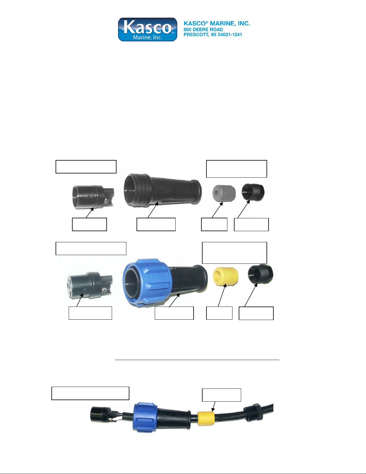
Figure 1: Pin Insert
Note:
Grey gland for 14 gauge
Main Body Pin insert Gland
Gland Nut
_______________________________________ __________________________________________ ___
Figure 2: Socket Insert
Main Body Socket insert Gland
Note:
White gland for 12 gauge
Yellow gland for 10 gauge
Gland Nut
_____________________________________________________________________________________
Assembly/Wiring Instructions
Step 1: Remove the pin or socket insert from the housing of the connector. There is a slot for a flat blade
screwdriver in the center of the insert.
Note: The inserts have a
LEFT HAND THREAD and should be turned clockwise to remove.
Step 2: Remove the gland nut and gland from the rear of the housing and slide on to the cable. Make sure
the gland is orientated with the stepped edge facing the nut (see Figure 3).
Figure 3: Wire Assembled
Stepped Edge
(continued)

Step 3: Prepare the cable and strip wire ends as shown in figure 4.
Figure 4: Wire stripping Detail
Step 4: Insert the stripped wire ends into the terminals on the back of the Pin/Socket insert and fully
tighten the wire retention screws.
(Refer to Figure 5 for correct wire orientation.)
Figure 5:
Wire Connections
Black wire to terminal L
White wire to terminal N
Green wire to terminal E
After the wires have been connected securely, pull the cable and insert back into the housing and tighten
with a screwdriver to ensure the insert is seated correctly.
counter clockwise to tighten.
Step 5: Using the Black Potting Resin, apply
enough resin into the housing to cover the
wires and contacts. The resin should be about
1/8” onto the cord jacket.
much resin will cause excess to be forced into
female end of the pin connector, preventing
proper connection of the two halves.
Step 6: Slide the gland and
gland nut along the cable into
the body and tighten
the gland nut securely.
Repeat Steps 1 through 6 to assemble the remaining half of your quick disconnect assembly.
Once the two subassemblies have been completed, they can be joined together. Plug pin assembly into the
socket assembly and tighten the large blue nut securely. The blue nut should be hand tightened only.
(See figure 6)
Note: Adding too
Figure 6: Tightened Assembly
Note: LEFT HAND THREAD, turn the insert
Cut-Away disconnect
shown with clear resin.
Note amount that is
covering cord jacket.
Note: There is a small gap after tightening
For seasonal removal, your quick disconnect includes an optional water tight cover. Simply separate the
quick disconnect and insert the sealing cover into the large blue nut half an d tighten firmly.
Kasco Marine, Inc.
Phone (715) 262-4488
www.kascomarine.com • sales@kascomarine.com Rev 6 12-18-2006
800 Deere Road, Prescott, WI 54021-1241
•
Fax (715) 262-4487
 Loading...