

Kasco LR375 User Manual
Owners Manual
Submersible Light Kits
LR275 & LR375
Contents
Important Safety. . . . pg2
General Instructions. . . . pg3
PARTS INCLUDED. . . . pg3
LR275 Light Kit Assembly Instructions. . . . pg3
LR375 Light Kit Assembly Instructions. . . . pg4
Instructions On Adapter Kit For 6 Lights. . . . pg5
Maintenance Recommendations. . . . pg6
Warranty Policy. . . . pg7
Troubleshooting Tips. . . . pg8
Replacement Parts Diagram. . . . pg9
Customer Repair Form. . . . pg10
Registration Information. . . . pg12
C
Intertek
3020379
UL 676 8th Ed. 2003
Kasco Marine, Inc.
800 Deere Rd.
Prescott, WI 54021
PH (715) 262-4488
FAX (715) 262-4487
www.kascomarine.com
Rev. 02/22/11

THANKS
We at Kasco Marine, Inc. would like to both thank and
congratulate you on your purchase of the Submersible
Light Kit. The Submersible Light Kit will illuminate
your fountain for a beautiful display. We thank you
for choosing Kasco for your fountain and aeration
needs and want you to be completely satisfi ed with
your purchase.
Important Safety
Please read and follow these extremely important
safety and handling instructions for your Kasco equipment. Following these instructions will help ensure
your safety and the quality performance of your equipment.
Under NO circumstances should anyone enter •
the water with the electrical equipment plugged
in and/or in operation. All Kasco equipment is
designed and built to UL and CSA standards for
safety in water and all fountain models include
control panels with GFCI protection. However, it
is NEVER recommended to enter the water with
the equipment in operation.
Kasco’s Submersible Light Kits are intended for •
use with a Listed control panel having a GFCI
protected receptacle or fi eld wiring terminals and
disconnect switch, or a timer with a disconnect for
use with a GFCI receptacle. They are intended
to be mounted on a fl oating fountain or aerator
for use in a natural or man-made body of water to
comply with NEC Article 682.
Kasco’s Submersible Light Kits have not been •
evaluated for use in swimming pools, spas or stationary fountains.
All serviceable parts of the light kit are low volt-•
age (12Vac). The power connection for the light
kit is 120Vac and MUST be plugged into a GFCI
receptacle or GFCI protected fi eld terminal con-
nections.
Caution should be used when dealing with any •
electrical and/or moving equipment.
NEVER run the unit out of water. It could create a •
dangerous situation for the operator.
Extreme caution should be used around water, es-•
pecially cold water, as in Spring, Fall, and Winter,
which poses a hazard itself.
NEVER lift or drag the fountain or light kit by the •
power cords. If you need to pull the unit to the
side of the pond, use the anchoring ropes.
Do not use waders in ponds/lakes that are deep, •
with drop-offs, drastic slopes, or soft bottom material.
Do not use a canoe or boat that tips easily during •
installation
The light kit is supplied with an internal ground-•
ing conductor and a grounding-type attachment
plug. To reduce the risk of electrical shock, be
certain that the light kit is connected to the GFCI
protected lighting circuit of your control panel.
For more information regarding your control
panel instructions, refer to your fountain owners
manual or download control panel wiring diagrams
from http://kascomarine.com/instructions.html. A
control panel must be installed a minimum of 5
feet (3m in Canada) from the body of water unless
separated from the body of water by a fence, wall,
or other permanent barrier that will make the unit
inaccessible to persons in the water.
2
General Instructions
INSPECT THE SHIPMENT
Immediately inspect your Kasco Submersible Light
Kit shipment for any visible damages. Also cross
reference the “Parts Included” section to check for part
shortages. Shortages should be reported immediately
to your Kasco Marine distributor or representative and
damages reported to your carrier and Kasco Marine.
PARTS INCLUDED
LR275
A. Light Kit with cord (1)•
B. 75-watt, 12-volt, MR-16 Halogen Bulbs, in-•
stalled in fi xtures (2)
C. 1/4” x 1” Stainless Steel Bolts (2)•
D. 1/4” Stainless Steel Flat Washer (2)•
E. 1/4” Stainless Steel Lock Washer (2)•
F. 1/4” Stainless Steel Nut (2)•
G. Nylon Cable Tie•
H. Optional Colored Bulbs•
LR275 Light Kit Assembly
Instructions
Instructions for mounting lights on:
Model 2400VFX, 3400VFX, 3400HVFX, 3400JF, &
3400HJF Aerating Fountains
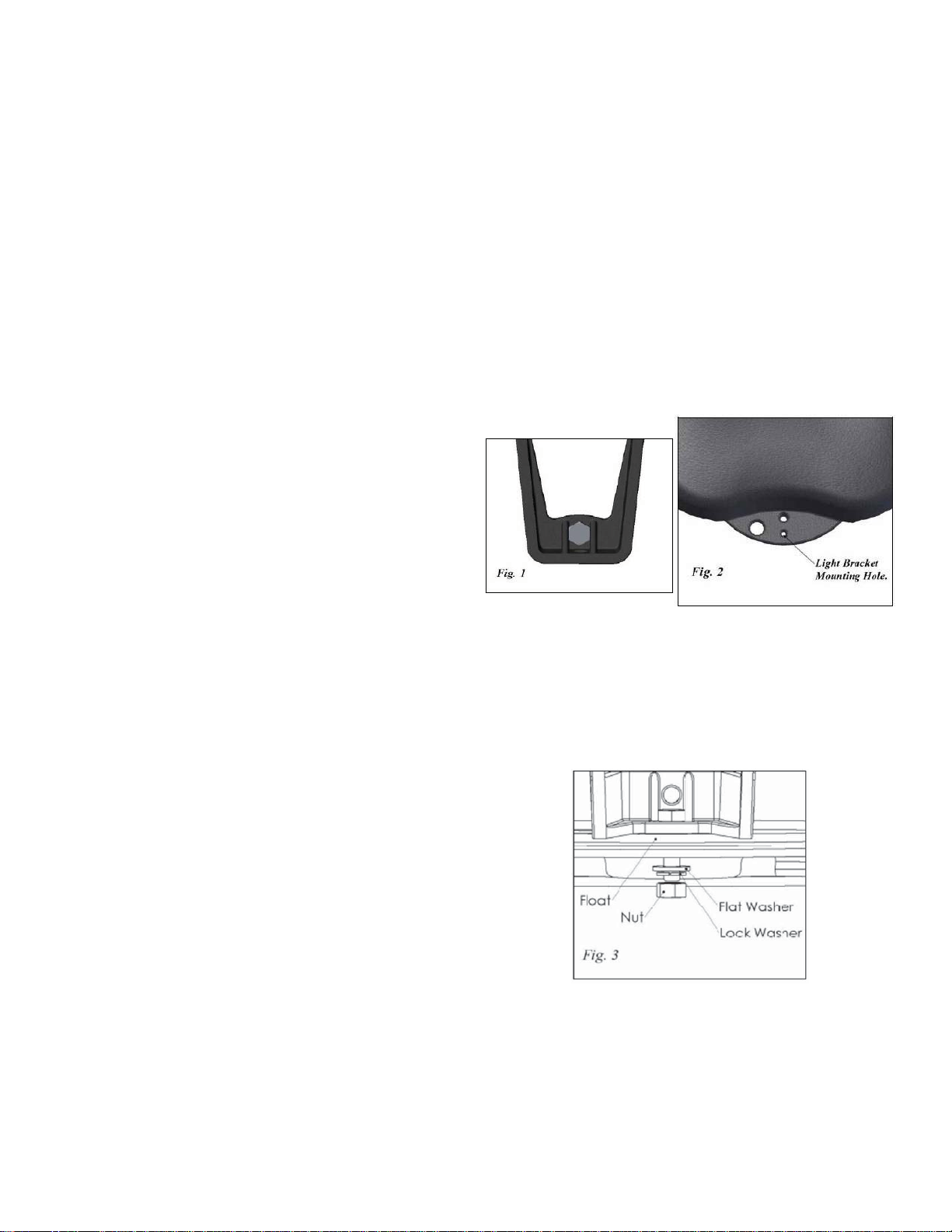
STEP ONE:
Cut Nylon Zip Ties that hold the fi xture cords in a coil.
Insert the 1/4” x 1” bolt into the light bracket so the
fl ats of the hex head bolt are between the support ribs
of the bracket as shown in Figure 1. Align the light
bracket to the fl oat tab by placing the bolt through the
light mounting hole in the underside of the fl oat tab as
shown in Figure 2.
Note: Extra hardware may be included.
LR375
A. Light Kit with cord (1)•
B. 75-watt, 12-volt, MR-16 Halogen Bulbs, in-•
stalled in fi xtures (3)
C. 1/4” x 1” Stainless Steel Bolts (3)•
D. 1/4” Stainless Steel Flat Washer (3)•
E. 1/4” Stainless Steel Lock Washer (3)•
F. 1/4” Stainless Steel Nut (3)•
G. Nylon Cable Tie•
H. Optional Colored Bulbs•
Note: Extra hardware may be included.
TOOLS & SUPPLIES NEEDED
A. 7/16” Wrench•
B. Flat Head Screw Driver•
C. Diagonal Pliers or Cutter for Nylon Zip Ties•
STEP TWO:
Install the 1/4” Flat Washer, 1/4” Lock Washer and
1/4” Nut against the underside of the fl oat tab as
shown in Figure 3. Tighten the nut until snug using
the 7/16” Wrench.
STEP THREE:
Adjust the angle of the light as desired and tighten the
two brass screws on the sides of the fi xture until snug.
Do not over tighten. It is best to have all two or three
fi xtures at the same angle.
3
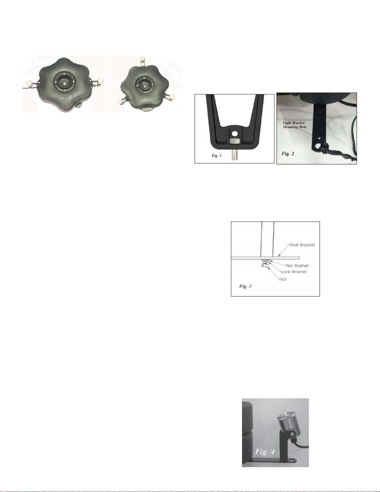
STEP FOUR:
Repeat steps 1 through 3 for the remaining fi xture.
The completely assemble light fi xture is pictured in
Figure 4. Note the orientation of the lights.
STEP TWO:
Cut Nylon Zip Ties that hold the fi xture cords in a
coil. Insert the 1/4” x 1” bolt into the light bracket so
the fl ats of the hex head bolt are between the support
ribs of the bracket as shown in Figure 1. Align the
light bracket to the lower fl oat bracket by placing the
bolt through the light mounting hole in the lower fl oat
bracket as shown in Figure 2.
Figure 4
2 light install
Figure 5
3 light install
STEP FIVE:
Upon installation of the assembled unit, connect your
lighting package to your fi eld installed GFCI protected
outlet and timer. .
STEP SIX:
Using the nylon cable tie provided, tie the light kit
power cord to the fl oat opposite the fountain power
cord. This will keep the cord from being damaged by
the fountain and balance the unit properly.
Note:
Each light fi xture and cord entrance must be sub-
merged at least 1” in order for lights to operate properly.
LR375 Light Kit Assembly
Instructions
Instructions for mounting lights on:
Model 4400VFX, 4400HVFX, 8400VFX, 8400JF,
3.1JF & 5.1JF Aerating Fountains
STEP THREE:
Install the 1/4” Flat Washer, 1/4” Lock Washer and
1/4” Nut against the lower fl oat bracket as shown in
Figure 3. Tighten the nut until snug using the 7/16”
Wrench.
STEP FOUR:
Adjust the angle of the light as desired and tighten the
two brass screws on the sides of the fi xture until snug.
Do not over tighten. It is best to have all three fi xtures
at the same angle.
NOTE: For 4400VFX & 4400HVFX follow Assembly Instructions for LR275, but repeat with third light
fi xture. See Figure 5 in LR275 Assembly for correct
orientation. Also use LR275 instructions
If you purchased the LR375 for use on 2400 & 3400
models.
STEP ONE:
For ease of assembly, make sure the Aerating Fountain
is completely assembled. Place the assembly upright
and if needed, use blocks to support the fl oat.
4
STEP FIVE:
Repeat steps 2 through 4 for the remaining two fi x-
tures. The completely assemble light fi xture is pic-
tured in Figure 4.
 Loading...