

Owners Manual
Submersible Light Kits
Models LED3125 & LED6125
Contents
Important Safety. . . . pg2
General Instructions. . . . pg2
Parts Included. . . . pg2
LED3125 Assembly Instructions. . . . pg3
Instructions For Mounting LED6125. . . . pg5
Maintenance Recommendations. . . . pg6
Warranty Policy. . . . pg7
Troubleshooting Tips. . . . pg8
Replacement Parts. . . . pg9
Customer Repair Form. . . . pg10
Registration Information. . . . pg12
Kasco Marine, Inc.
800 Deere Rd.
Prescott, WI 54021
PH (715) 262-4488
FAX (715) 262-4487
www.kascomarine.com
Rev. 06/17/14

THANKS
We at Kasco Marine, Inc. would like to both thank and
congratulate you on your purchase of the Submersible
LED Light Kit. This kit will illuminate your fountain
for a beautiful display. We thank you for choosing
Kasco for your fountain and aeration needs and want
you to be completely satised with your purchase.
Important Safety
Please read and follow these extremely important
safety and handling instructions for your Kasco equipment. Following these instructions will help ensure
your safety and the quality performance of your equipment.
with drop-offs, drastic slopes, or soft bottom material.
• Do not use a canoe or boat that tips easily during
installation
• To reduce the risk of electrical shock, be certain
the light kit is connected to the GFCI protected
lighting circuit of your control panel. For more
information regarding your control panel instructions, refer to your fountain owner’s manual or
download control panel wiring diagrams from
http://kascomarine.com/instructions.html. A control panel must be installed a minimum of 5 feet
(3m in Canada) from the body of water unless
separated from the body of water by a fence, wall,
or other permanent barrier that will make the unit
inaccessible to persons in the water.
• Under NO circumstances should anyone enter
the water with the electrical equipment plugged
in and/or in operation. All Kasco equipment is
designed and built for use in water, and control
panels are available with GFCI protection. However, it is NEVER recommended to enter the water
with the equipment in operation.
• Kasco’s Submersible Light Kits are intended for
use with a Listed control panel having a GFCI
protected receptacle, or eld wiring terminals and
disconnect switch, or a timer with a disconnect for
use with a GFCI receptacle. They are intended
to be mounted on a oating fountain or aerator
for use in a natural or man-made body of water to
comply with NEC Article 682.
• Kasco’s Submersible Light Kits have not been
evaluated for use in swimming pools, spas or stationary fountains.
• The power connection for the light kit is 120Vac
and MUST be plugged into a GFCI protected
receptacle or GFCI protected eld terminal connections.
• Caution should be used when dealing with any
electrical and/or moving equipment.
• NEVER run the unit out of water. It could create a
dangerous situation for the operator.
• Extreme caution should be used around water, especially cold water, as in Spring, Fall, and Winter,
which poses a hazard itself.
• NEVER lift or drag the fountain or light kit by the
power cords. If you need to pull the unit to the
side of the pond, use the anchoring ropes.
• Do not use waders in ponds/lakes that are deep,
General Instructions
INSPECT THE SHIPMENT
Immediately inspect this shipment for any visible
damages. Also cross reference the “Parts Included”
section to check for part shortages. Shortages should
be reported immediately to your Kasco Marine distributor or representative and damages reported to your
carrier and Kasco Marine.
Parts Included
LED3125
• A. Light Kit cord with waterproof connectors (1)
• B. Sealed LED light xtures with ex sleeve (3)
• C. 1/4” x 1 3/8” Stainless Steel Bolts (3)
• D. 1/4” Stainless Steel Flat Washer (3)
• E. 1/4” Stainless Steel Lock Washer (3)
• F. 1/4” Stainless Steel Nut (3)
• G. Nylon Cable Ties (9)
• H. Stainless steel mounting brackets & hardware (3)
• I. Sealing cap (3)
• J. 4” spacer washers (3)
• K. 1/4” x 5” Stainless Steel Bolts (3)
• L. Spare Oring (1)
• M. Rubber caps (3)
• N. Colored lenses (20 - 4 of each color)
Note: Extra hardware may be included. One extra
spare oring is included. One extra lens of each color is
included.
2
LED6125
• A. Includes two (2) sets of LED3125 (see parts
included in LED3125
• B. Lower oat brackets (6)
• C. 3/8” washers (3)
TOOLS & SUPPLIES NEEDED
• A. Two 7/16” Wrenches (or one wrench & a 7/16
socket with driver)
• B. Diagonal Pliers or Cutter for Nylon Zip Ties
LED3125 Assembly Instructions
For ease of assembly, make sure the Aerating Fountain
is completely assembled. Place the assembly upright.
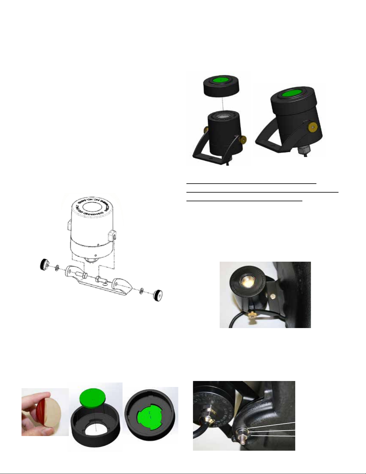
1. Install the mounting brackets to the light xtures by
tting the head of the #10 screw into the tabs on each
side of the xture. Tighten the thumb screws on each
side hand tight only.
Fig 1
3. Place rubber caps over the light xtures as shown.
Ensure the rubber cap is seated all the way down onto
the xture housing. If this is not on a new light kit,
make sure the xture and lens are clean before install-
ing the rubber cap.
Fig 3
Instructions for mounting lights on model:
2400VFX, 3400VFX, 3400HVFX, 3400J, 3400HJ,
4400VFX, 4400HVFX, 4400J, 4400HJ
Installing Color Lenses:
If you desire to change to one of the color choices
instead of the standard white light, follow these steps.
2. Unpeel the protective backing from both sides of
the colored lens on the color of your choice. Place the
lens inside the rubber cap making sure the 3 aps are
holding the lens in place. Do this for all 3 lenses.
Fig 2
4. Insert the 1/4” x 1-3/8” bolt into the light xture
bracket. Align the light xture bracket to the oat
tab by placing the bolt through the light mounting
hole (light xture bracket is on top of the oat tab) as
shown in Figure 4.
Fig 4
5. Install the 1/4” Flat Washer, 1/4” Lock Washer
and 1/4” Nut against the underside of the oat tab as
shown in Figure 5. Tighten the nut until snug using
the 7/16” Wrench.
Fig 5
at washer
lock washer
1/4” nut
3
6. Adjust the angle of the light as desired and tighten
the two brass thumb screws on the sides of the xture
until snug. Do not over tighten. It is best to have all
three xtures at the same angle.
7. Repeat steps 1 through 4 for the remaining xtures.
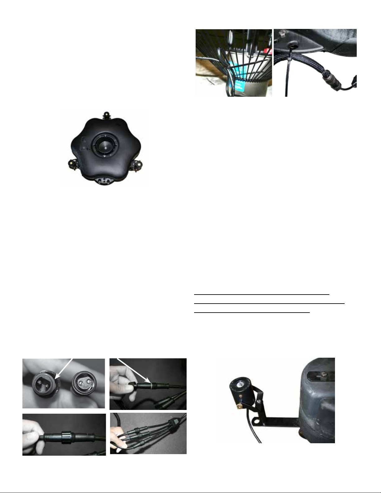
Assembled light xtures are pictured in Figure 6. Note
the orientation of the lights.
Fig 6
8. Connect each xture cord to the power cord’s wa-
terproof connectors.
Fig 8
9. Upon installation of the assembled unit, connect
your LED light kit to your eld installed GFCI protected outlet and timer.
Note:
Installation of these LED light xtures on the above
listed aerator/fountain units will ensure proper submersion of the light xtures. Each xture must be partially submerged in order for lights to operate properly.
Other applications for these xtures must provide at
least the same submersion to properly cool the xture.
Operating the xtures out of water will damage the
LED and void warranty.
Make sure the orange oring is installed on the plug
side of the waterproof connector. If any are miss-
ing, check the packaging to see if any fell off during
shipping, or an extra oring was included if there is one
missing.
Hand tighten the waterproof connectors as shown in
Figure 7. Using a cable tie, tie the light kit power cord
to the oat opposite the fountain power cord. This
will keep the cord from being damaged by the fountain and balance the unit properly.
Next, cable tie each xture cord to the oat to protect
each xture cord as shown in Figure 8.
Fig 7 Check for orange oring
A sealing cap is provided for eld removal of one light
xture. If a xture fails to operate it can be removed
and the cap installed onto the waterproof connector of
the power cord. This will allow you to continue to op-
erate your light kit with two xtures while a replacement xture is procured.
Instructions for mounting lights on model:
8400VFX, 8400JF, 2.3VFX, 2.3JF, 3.1JF, 3.3JF,
5.1JF, 5.3JF, 5.1VFX, 5.3VFX, 7.3JF
4. Insert the 1/4” x 5” bolt into the light bracket and
extension as shown in Figure 9. Place this assembly
on the oat bracket
Fig 9
4

5. Install the 1/4” Flat Washer, 1/4” Lock Washer and
1/4” Nut as shown in Figure 10. Tighten the nut until
snug using the 7/16” Wrench.
Fig 10
at washer
lock washer
1/4” nut
Fig 11 Check for orange oring
Fig 12
6. Adjust the angle of the light as desired and tighten
the two brass thumb screws on the sides of the xture
until snug. Do not over tighten. It is best to have all
three xtures at the same angle.
7. Repeat steps 1 through 4 for the remaining xtures.
Assembled light xtures are pictured in Figure 4. Note
the orientation of the lights.
8. Connect each xture cord to the power cord’s wa-
terproof connectors.
Make sure the orange oring is installed on the plug
side of the waterproof connector. If any are miss-
ing, check the packaging to see if any fell off during
shipping, or an extra oring was included if there is one
missing.
Hand tighten the waterproof connectors as shown in
Figure 11. Using a cable tie, tie the light kit power
cord to the oat opposite the fountain power cord.
This will keep the cord from being damaged by the
fountain and balance the unit properly.
Next, cable tie each xture cord to the oat to protect
each xture cord as shown in Figure 12.
9. Upon installation of the assembled unit, connect
your LED light kit to your eld installed GFCI protected outlet and timer.
Instructions For Mounting LED6125
Instructions for attaching brackets on the oat prior
to mounting the light xtures on 2 HP or larger Kasco
units.
Parts needed:
• Lower oat brackets (6)
• 3/8” washers (3)
Part 1
Part 2
5

1. Turn the unit upside down. Loosen and remove the
3/8” nuts on the three 9” bolts that are closest to the
motor unit. Place 2 Lower Float Brackets(Part #1) and
one 3/8” washer(Part #2) on each of the 9” bolts over
the bottom screen clips and replace the 3/8” nut.
can also alert you to electrical leaks in the equipment. If
you have repeat, consistent trips of the ground fault device,
the equipment should be disconnected and removed from
the water. The power cord should be inspected for damage and you should contact your distributor, or call Kasco
Marine at 715-262-4488 for further instructions or email
Kasco at sales@kascomarine.com.
OBSERVATION: Operating equipment should be observed
on a regular basis (daily, if possible) for any reduction or
variation in performance. If a change in performance is observed, the equipment should be disconnected from power
and inspected.
2. Arrange the brackets into the position shown and
tighten down the nuts. Once the brackets are secure,
turn the unit back into its upright position.
3. Follow the instruction on the previous page
(LED3125 Assembly instructions) to mount the light
kit to the brackets.
Maintenance Recommendations
• Under No Circumstances should anyone enter the
water while a fountain is operating.
• Please keep the original box for maintenance shipping.
The following maintenance procedures can be utilized to
ensure many years of quality performance from your Kasco
Fountain and Light Kit and reduce the need for more costly
repair work.
PROPER INSTALLATION: Proper installation of Kasco
equipment will include a power source with ground fault
protection. For Fountain models, Kasco provided control
panels included with the unit have built-in ground fault protection. Ground fault interrupters are a safety feature that
WINTER STORAGE: In regions where there is signicant
freezing in the wintertime, the fountain and light kit should
be removed from the water to protect them from the expansion pressure of the ice. In many areas, fountains will keep
some amount of ice open through the winter. However,
when the water is thrust into the air, it is exposed to the
colder air temperatures longer and can actually make ice
thicker on the pond/lake. Storage over winter is best in a
location that is out of the sun and cool, but above 32° F.
CLEANING: Fountains and light kits should be removed
from the water at least once per year (at the end of the
season in cold climates) to clean the exterior of the system, especially the stainless steel motor housing (can) and
light xtures. The motor housing and light xture surfaces
dissipate heat into the water and any algae, calcium, etc.
build-up will become an insulator that blocks heat transfer. In warmer regions it is recommended that the motor
is removed and cleaned at least two to three times per year
depending on conditions. In most cases a power washer
will be sufcient if the unit and algae are still wet. Also
make sure the lens of the light xtures is clean to ensure the
brightest light possible.
FIXTURE REPLACEMENT: The LED light xtures
are sealed and do not require any maintenance other than
cleaning. If a xture fails to operate it can be removed and
the sealing cap installed onto the waterproof connector of
the power cord. This will allow you to continue to operate
your light kit with two xtures while a replacement xture
is procured. Only perform this removal/replacement with
all equipment disconnected from the power source.
Any required repairs need to be performed by Kasco Marine. Any alterations or changes made to Kasco units by an
unauthorized source will void the warranty. This includes
tampering with the unit, power cord, and/or control box.
Please contact Kasco Marine, Inc. at 715-262-4488
or sales@kascomarine.com.
6

Warranty Policy
1 Year Limited Warranty: Kasco® Marine, Inc. warrants
this Light Kit to be free from defects in material or workmanship under normal use and service. The Kasco Marine,
Inc. obligation under this warranty is limited to replacing
or repairing free of charge any defective part within one (1)
year from the date of shipment. Customer shall pay shipping charges for returning the unit to Kasco.
THIS WARRANTY IS IN LIEU OF ANY OTHER
WARRANTIES, EXPRESSED OR IMPLIED, AND ANY
OTHER OBLIGATION OR LIABILITY WHATEVER
ON THE PART OF KASCO MARINE, INC. AND IN NO
EVENT SHALL KASCO MARINE, INC. BE LIABLE
FOR ANY SPECIAL OR CONSEQUENTIAL DAMAGES.
Warranty is void if:
The Light Kit is not maintained properly according to the
Maintenance Recommendations supplied in this Owner’s
Manual.
The lights, control box, or power cord are altered in any
way from original shipment. Cuts in the power cord are not
covered under warranty.
Any expedited shipping method for the return of the unit is
at the customer’s expense. Kasco Marine will return units
repaired under warranty at our expense via ground freight
Non-Warranty Repairs:
Most failed equipment can be repaired at substantially
lower costs than replacement with new. If your light kit
requires repair and is no longer covered under warranty,
please contact Kasco Marine for current repair pricing.
Please ship according to the instructions in the previous
section. Again, it is best to call ahead for a Return Authorization Number and/or Repair Form so we know the repair
is coming.
All light kits that are rejected for repair will be destroyed
unless otherwise directed by the customer. If the customer
would like the Light Kit returned, it will be restored as
closely as possible to the condition in which it was received
and shipped at the customer’s expense for shipping and
handling charges.
Billing:
All non-warranty repairs will be returned to the customer
and billed C.O.D. unless otherwise directed. Kasco Marine
also accepts Visa and MasterCard credit card payments.
Kasco Marine will call for credit card information upon
completion of the estimate at the customer’s request.
The Light Kit is damaged by unauthorized tampering.
Warranty Claim Procedure:
The warranty coverage can be established by the date of
purchase receipt or by calling Kasco Marine, Inc. Please
call Kasco Marine at 715-262-4488 prior to shipping to receive a Return Authorization Number and/or Repair Form,
then ship to:
Kasco Marine, Inc.
800 Deere Rd.
Prescott, WI 54021
Attn: Repairs
You can also email Kasco at sales@kascomarine.com .
Note: Please contact Kasco to determine if the main power
cord needs to be returned to be considered for warranty.
The power cord may be needed to diagnose the failure.
Please include the Repair Form received from Kasco
Marine or your local distributor with the shipment. If no
Repair Form is available, include your name and physical
address for return delivery of the repaired Light Kit and
a daytime phone number and/or e-mail address for correspondence regarding the warranty claim.
All other warranty and repair inquiries should be directed
to Kasco Marine, Inc. at 715-262-4488 or
sales@kascomarine.com .
7

Troubleshooting Tips
e
y
Troubleshooting tips - light kit
The following is provided to help diagnose a probable source of trouble. It is a guideline only and may not show all causes for all problems. For additional
troubleshooting help contact your local distributor or visit www.kascomarine.com for additional help.
NOTE: you may need to refer to your owners manual that was provided with your fountain for additional control panel settings and adjustments.
Problem Possible Caus
Power is off or disconnected
Not dark enough for photo
Timer not set properly
Light kit is installed and
wired, but will not turn
on.
eye to activate
Likely Remed
Ensure control panel is connected to the electrical circuit. Verify circuit breakers, timers, and/or
interlock switches are turned on and functional. Refer to your owners manual that was provided with
the fountian.
C-25 control panel:
The control panel has a photo eye on the left side of the enclosure exterior. This photo eye measures
ambient light. To activate, the photo eye must not measure any ambient light for at least several
minutes. Also, the C-25 timer must be turned on (fountain operating) to allow the light circuit to
energize. Covering the photo eye with black electrical tape will activate the photo eye for testing.
C-85, or C-95 control panel with GFCI outlet and photo eye control:
The control panel has a photo eye on the left side of the enclosure exterior. This photo eye measures
ambient light. To activate, the photo eye must not measure any ambient light for at least several
minutes. Also, the fountain timer must be turned on (fountain operating) to allow the light circuit to
energize. Covering the photo eye with black electrical tape will activate the photo eye for testing.
While the photo eye is covered, the GFCI outlet can be reset if tripped.
C-85, or C-95 control panel (and all 3phase fountain control panels) with terminal connections
and timer control for light kit:
The control panel has a second timer for controlling the lights (No photo eye). Ensure the light timer
is set to operate the lights. The timer has a built in Hand-Off-Auto swith. Ensure the switch is set
properly.
Ensure the fountain is turned on. The light timer will not energize the light kit unless the fountain
C-25 control panel:
Reset the GFCI. If the GFCI does not reset it could be a ground fault in the fountain wiring, or the light
kit wiring. Unplug both the fountain and light kit and reset the GFCI. If it resets, plug fountain then
light kit back in and see which one trips the GFCI. If the GFCI does not reset with both unplugged,
then the GFCI may be defective.
C-85, or C-95 control panel with GFCI outlet and photo eye control:
To reset the GFCI outlet the fountain timer must be turned on, and the photo eye must be activated.
(black electrical tape can be wrapped around the photo eye to activate it). Once these are on, the
GFCI reset button can be pressed. (unplug the light kit prior). Plug the light kit in and see if it
operates. If the GFCI trips again then the light kit may be damaged. If the GFCI does not reset (with
light kit unplugged) then it may be defective or the photo eye is not activated to send power to the
outlet.
Light work. However,
they are not as bright as
when first installed.
8
GFCI is tripped
Dirty lenses
C-85, or C-95 control panel with terminal connections and timer control for light kit:
For panels with a GFCB (ground fault circuit breaker) and timer controlled lights, simply reset the two
pole breaker. This will turn the fountain and light kit back on if the timers are set to on! If it trips again,
disconnect the light kit from the terminals and reset. WARNING! you must turn off power to the panel
before disconnecting any wiring from the terminals! If the breaker trips with the light kit
disconnected, then disconnect the fountain as well and reset. If the breaker continues to trip it may
be a defective GFCB. If the breaker resets, then reconnect the fountain then the light kit to see which
one trips the GFCB.
3phase fountain control panels:
3phase fountain panels have a ground fault sensing module that will trip if either the light kit or
fountain has a ground fault. To reset the module, simply press the reset button in the panel. This will
turn the fountain and light kit back on if the timers are set to on! If it trips again, disconnect the light
kit from the terminals and reset. WARNING! you must turn off power to the panel before
disconnecting any wiring from the terminals! If the GFI module trips with the light kit disconnected,
then disconnect the fountain as well and reset. If the GFI module continues to trip it may be a
defective module or an internal wiring issue with the panel. If the module resets, then reconnect the
fountain then the light kit to see which one trips the module.
Turn of power to the control panel and disconnect power cords to the fountain and the light kit.
Bring the fountain to the shore and inspect the light lenses. Over time, algae growth and hard water
deposits on the lenses can block light output. Clean the lenses with a soft brush and the light should
be bright again.

Replacement Parts
ITEM NO.
PART NUMBER DESCRIPTION QTY.
1 345105 LED FIXTURE, 1M CORD 1
2 345007 BRACKET 1
3 345042 SCREW, #10-32 X 1/2", HEX HEAD 2
4 771037 WASHER, #10 SPLIT LOCK 2
5 345043 10-32 THUMB NUT 2
6 345035 O-RING, LED CORD CONNECTOR 1
7 584692 1/4-20 X 1-3/8" BOLT 1
8 258476 FLAT WASHER, 1/4" 1
9 840537 LOCK WASHER, 1/4" 1
10 840536 NUT, 1/4-20 1
11 345046 SCREW, 1/4-20 X 5", HEX HEAD 1
12 345047 SPACER, ROUND, 4INCH 1
13 345051 CAP, LENS 1
14 345053 KIT, LED COLORED LENS 1
13
KIT CONTAINS 4 EACH
14
OF 5 DIFFERENT COLORS
11
45 7
2
12
1
3
8
6
9
ITEMS 7-10 REQUIRED FOR SMALL
FLOAT MOUNTING (1/2HP-1HP)
10
ITEMS 8-12 REQUIRED FOR LARGE
FLOAT MOUNTING (2HP & LARGER)
LED REPLACEMENT PARTS FOR MODELS:
LED3125, LED4125 AND LED6125
9

800 Deere Rd.
Prescott, WI 54021
Phone: 715-262-4488 - Fax: 715-262-4487
www.KascoMarine.com Sales@KascoMarine.com
Customer Repair Form
* Important Reminders *
• All repairs sent in MUST be accompanied by a copy of this completed sheet!
• Address your Repair to Kasco Marine, Attn: Repairs (or to your Authorized Repair Center.
• Shipping to Kasco or an Authorized Repair Center is paid for by the customer.
• You must include the power cord with each unit sent in for repair to be considered for warranty repair!
• Do not ship the control box with the unit for repair, unless otherwise instructed.
Today’s Date:___________________
Customer Information
Name: _________________ Phone Number: _____________________
Address: __________________________ Alternate Number: ___________________
City: ____________________ Email Address: ______________________
State: _____________________
Zip Code: ______________________
Unit Information:
Model # (Ex. LED3125): ____________________
Serial # (Ex. 2101LEDA3025)___________________
Date Purchased: ________________________
Purchased From: _________________________
Earliest Date of Problem: _______________________
Description of Problem:
Comments:
10

11

Registration Information
Fill in the information below and keep for your records.
Model # (Ex. LED3125)_______________________________
Serial # (Ex. 2101LEDA3001)____________________________
Purchase Date:_____________________
Purchased From:___________________________________
Registration Date: ___________________________
12
Kasco Marine, Inc.
800 Deere Rd.
Prescott, WI 54021
Phone (715) 262-4488 • Fax (715) 262-4487
www.kascomarine.com • sales@kascomarine.com
884012
 Loading...