


Horizontal Float
Assembly & Installation Instructions
PARTS INCLUDED
A. Circulator (Unit with cord) (1)
B. Float in separate box (1) (Diagram to Right)
1. Float (1)
2. Base Strap (1)
3. Adjustment Bracket (1)
4. Angle Bracket (3)
5. Draw Band (1)
6. U-Bracket (2)
7. Spacer Bracket (2)
8. 1/4” x 1/2” Stainless Steel Bolt (8)
9. 1/4” x 1” Stainless Steel Bolt (3)
10. 1/4” x 1-1/4” Stainless Steel Bolt (2)
11. 1/4” Stainless Steel Lock Nut (8)
12. 1/4” Stainless Steel Hex Nut (2)
13. 1/4” Stainless Steel Lock Washer (5)
14. 50’ Black Nylon Ropes (2)
15. Nylon Tie (1)
TOOLS & SUPPLIES NEEDED
• 7/16” Wrench (1)
• 7/16” Socket & Ratchet (1)
• Felt-Tip Marker (1)
STEP ONE
Remove all contents from package and place on a
clean, flat surface. Inspect the shipment for any damages. If damages are found, immediately notify your
carrier and your Kasco Marine, Inc. representative.
Next, cross reference the parts included in the shipment with the Parts Included sheet in this manual on
page 14. Make sure you have all the parts needed. If
any shortages are found, contact your Kasco representative immediately.
STEP TWO
Position the Float upside down (lengthwise channels
facing up) and place the Base Strap so the three holes
in the Base Strap align with the three threaded holes
that comprise the lengthwise midline of the Float.
• Anchors or Stakes for Installation (2)
• 12” pieces of 1” galvanized pipe for weighting
ropes (optional) (2)
STEP THREE
Position the Adjustment Bracket over the two holes at
the back end of the Float and Base Strap. Loosely
secure the Adjustment Bracket to the Float using two
1/4” x 1/2” Stainless Steel Bolts and two Stainless
Steel Lock Washers. (See photo above for orientation.)
STEP FOUR
Place one of the three Angle Brackets perpendicular
to the Base Strap at the front end of the Base Strap.
One of the two center holes of the Angle Bracket
should be positioned over the hole in the Base Strap
and the threaded hole in the Float. Secure the Angle
Bracket to the Float using three 1/4” x 1/2” Stainless
Steel Bolts and three Stainless Steel Lock Washers.
(See photos on the next page for specific instructions
based on the size circulator purchased.) Tighten all
hardware at this time with the 7/16” socket and
wrench.
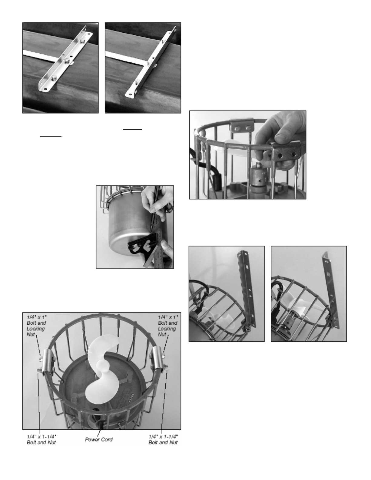
Models F2400, F3400
and 4400 - Angle
posterior
to bolts.
Model 8400 - Angle
anterior to bolts.
STEP FIVE
With a felt-tip marker, draw three to four marks
around the circumference of the motor housing at the
appropriate measurement from the back (or bottom)
of the motor housing
given below:
Model F2400: 3/4”
Model F3400: 3-3/8”
Model 4400: 3-3/8”
Model 8400: 3-1/4”
STEP SIX
Place the two U-Brackets directly across from each
other (180O) over the top ring of the motor cage. The
cord clamp on the cage should be 90O from each of
the U-Brackets. (See pictures on next page)
STEP SEVEN
Insert the Spacer Bracket under the U-Bracket and
inside the cage. Secure this assembly using one 1/4”
x 1” Bolt and a 1/4” Lock Nut, and one 1/4” x 1-1/4”
Bolt and a 1/4” Hex Nut. The longer bolt should be
on the side of the U-Bracket that is closer to the cord
clamp. Tighten the hardware using the 7/16” wrench
and socket & wrench until the U-Bracket clamps
firmly around the cage (U-Bracket should pull together slightly). Repeat with the second U-Bracket.
STEP EIGHT
Attach an Angle Bracket to each of the longer (11/4”) bolts on the U-Brackets (See photo for orientation) with a 1/4” Lock Nut.
Models F2400, F3400
and 4400
Model 8400
STEP NINE
Wrap the Draw Band around the motor housing and
position so that the back of the Draw Band touches
the marks drawn in Step Five. There is no front or
back to the Draw Band itself - it is reversible. Orient
the arm of the Draw Band so it aligns with the cord
clamp on the cage of the motor housing and is parallel to the Angle Brackets attached in Step Eight. Secure using a 1/4” x 1” Stainless Steel Bolt and a 1/4”
Lock Nut. (See photo on next page.)

Step Nine
STEP TEN
Attach the Angle Bracket on the motor to the Angle
Bracket on the Float using two 1/4” x 1/2” Bolts and
two 1/4” Lock Nuts (one set for each Bracket). See
photos for orientation based on model size. Also, the
cord clamp on the cage should be oriented toward the
Float.
Models 2400, 3400
and 4400
Model 8400
STEP ELEVEN
Attach the Draw Band on the motor to the Adjustment Bracket on the Float using a 1/4” x 1/2” Bolt
and a 1/4” Lock Nut. Select one of the five possible
positions to mount the Draw Band for your preferred
direction of flow (three are pictured on next page).
We do not recommend the two outer (most upward
and most downward) mounting positions for 8400
models.
Horizontal Angled Up Angled Down
STEP TWELVE
Attach the Ropes to the front (on the cage) and back
(around the Draw Band) of the motor. At this time,
use the Nylon Tie provided to connect the power cord
and front Rope to prevent the cord from tangling in
the prop. Also, if the power cord has a Quick Disconnect and Additional Strain Relief, attach the
Strain Relief to the cage of the unit and double check
the threaded collar on the Quick Disconnect to ensure
it didn’t loosen during shipping.
STEP THIRTEEN
Float the circulator in the water and position where
desired. Tie the front Rope to a stake on the shore or
weight. If a weight is used sink weight in front of
unit so rope is taught. (Circulator create great force,
make sure weight is enough to prevent movement.)
Tie back Rope to a stake on opposite shore or weight.
Sink weight behind the unit so rope is taught. At this
time take up any slack in the line.

The Industry Leader in
Ice Control Engineering.
KASCO MARINE, INC.
800 Deere Road
Prescott, WI 54021-1241
Phone (715) 262-4488 * Fax (715) 262-4487
www.De-Icer.com * sales@kascomarine.com
Rev. 7/10/06
820650
 Loading...