

Kasco 5.3E HJ User Manual [en, de, es, fr, it]

Owners Manual
50Hz Fountains
8400EJ, 3.1EJ, 3.1EVX
2.3E(H)J, 3.3E(H)J, 3.3E(H)VX, 5.3E(H)J
Contents
Important Safety Instructions . . . . . .pg2
Unit Specs . . . . . .pg2
Quick Disconnect Installation . . . . . .pg2
Wire Sizing & Gland Sizing . . . . . .pg4
Parts Included . . . . . .pg5
Assembly Instructions . . . . . .pg5
EVX Pattern Size Chart . . . . . .pg7
J Nozzle Options . . . . . .pg8
3 Phase Startup Procedure . . . . . .pg9
Installation Instructions . . . . . .pg10
Maintenance Recommendations . . . . . .pg10
Troubleshooting Tips . . . . . .pg11
Kasco Marine, Inc.
800 Deere Rd.
Prescott, WI 54021
U.S.A.
PH 00+1+715+262+4488
FAX 00+1+715+262+4487
sales@kascomarine.com
www.kascomarine.com
Rev. 12/15/09
CAUTION
NOTICE (NOTE)
These international safety symbols are used throughout this manual to inform the end user, installer, and
owner of important safety information and notices for
safe and effective use of the equipment.
test after wiring to ensure proper rotation of
the impeller. If the impeller is rotating in the
opposite direction, the unit will not perform
properly and internal damage to the unit may
occur. (See 3 phase startup procedure)
Means for disconnection must be incorporated •
in the fi xed wiring in accordance with local
and national wiring rules to prevent accidental
start.
Consult a qualifi ed electrician for electrical •
installation.
Important Safety Instructions
CAUTION
Under NO circumstances should anyone •
enter the water with the electrical equipment
plugged in and/or in operation. It is NEVER
recommended to enter the water with the
equipment in operation.
Caution should be used when dealing with any •
electrical equipment with moving parts.
NEVER run the unit out of water. It will •
damage the seals and create a dangerous
situation for the operator.
Extreme caution should be used around water, •
especially cold water, such as in Spring, Fall,
and Winter, which poses a hazard in and of
itself.
NEVER lift or drag the unit by the power or •
light cord. If you need to pull the unit to the
side of the pond, use the anchoring ropes.
Do not use waders in deep ponds/lakes or •
ponds/lakes with drop-offs, drastic slopes, or
soft bottom material.
Do not use boats that tip easily for fountain •
installation, such as a canoe, and follow all
boating safety rules and regulations, including
wearing a PFD. (Personal Flotation Device)
The unit is supplied with an internal grounding •
conductor. To reduce the risk of electrical
shock, be certain that the unit is plugged/
connected to an approved RCD (GFCI)
protected circuit.
A properly sized 3 phase motor control •
(motor starter) with overload and short
circuit protection must be provided at time of
installation.
3 phase units (2.3, 3.3, 5.3) require a startup •
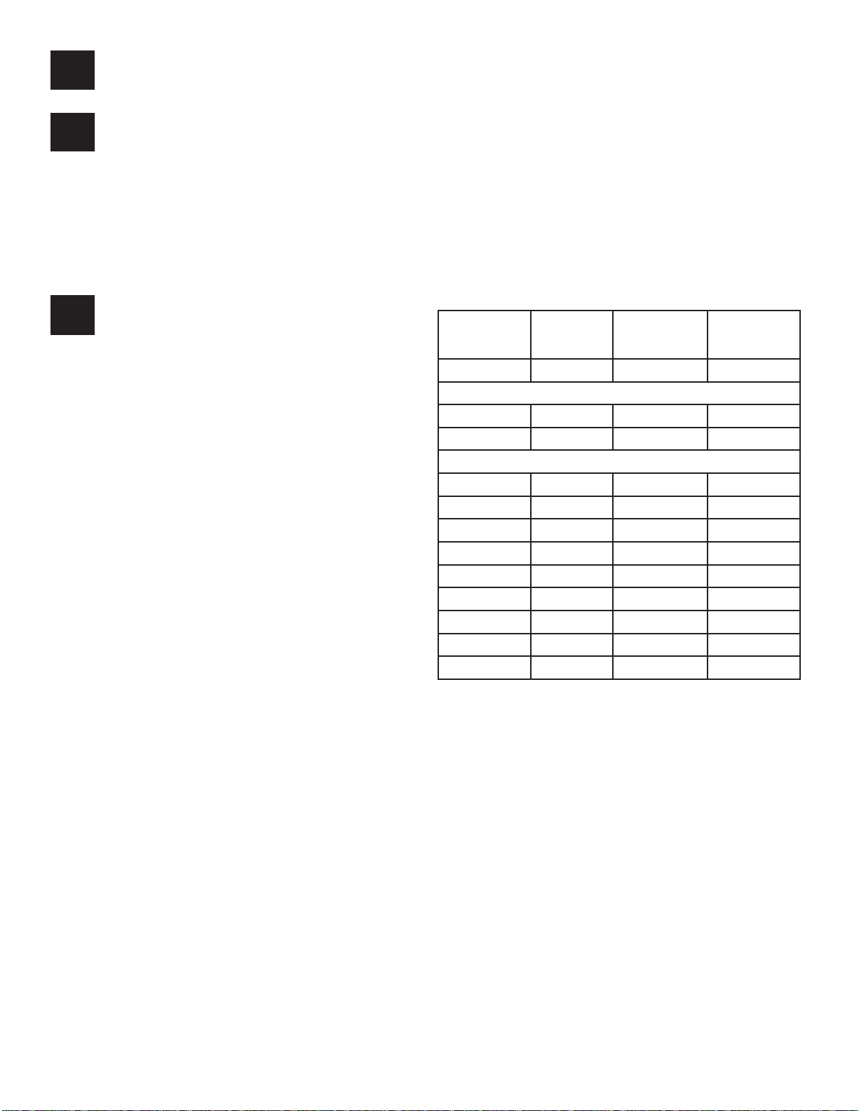
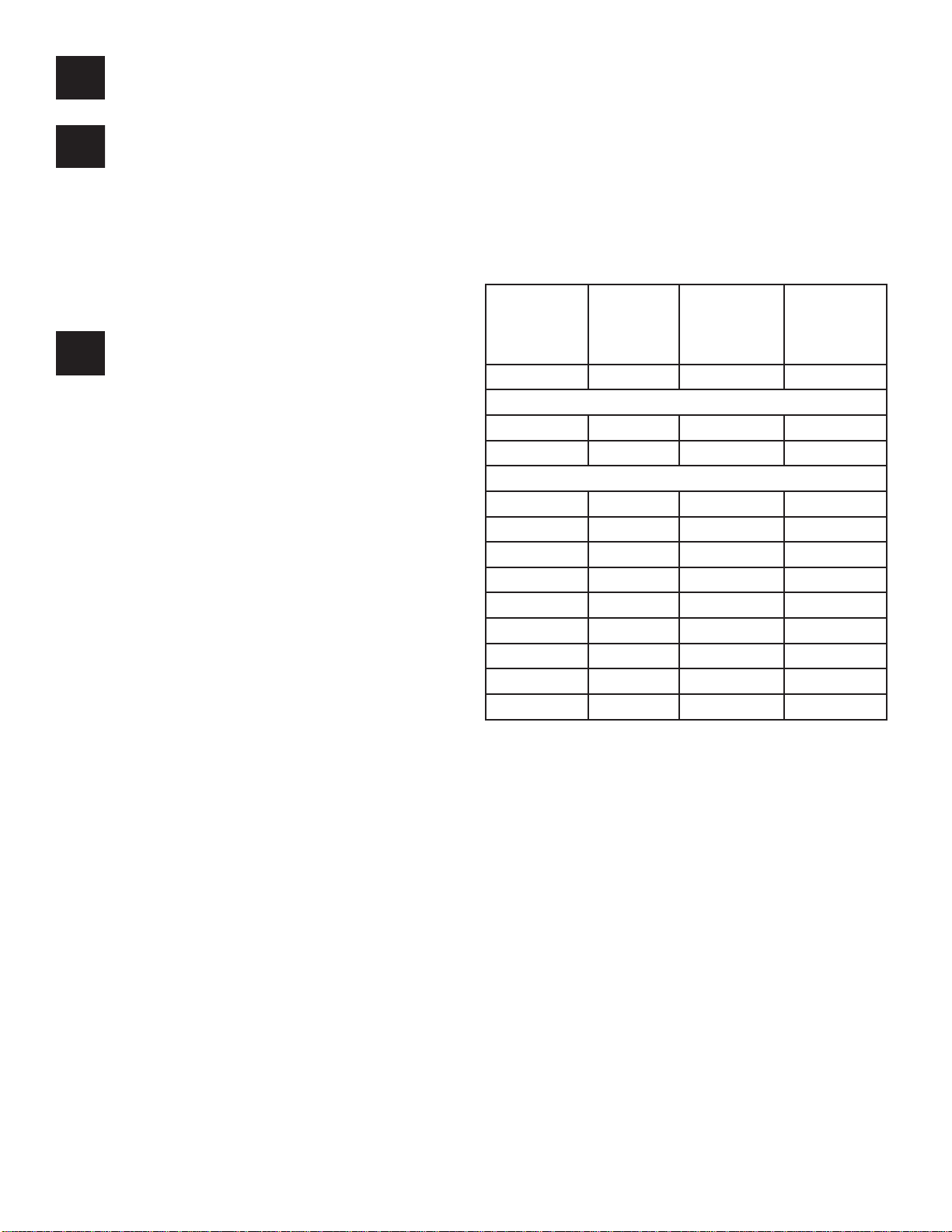
Unit Specs
Model Voltage
range
3.1EVX 208-240 12.5@220V 60@220V
8400EJ 208-240 9.5@220V 40@220V
3.1EJ 208-240 13.2@220V 60@220V
3.3EVX 190 9.6 69
2.3EJ 190 6.4 41
3.3EJ 190 10 69
5.3EJ 190 15.2 98
3.3EHVX 380 4.8 34
2.3EHJ 380 3.3 21
3.3EHJ 380 5 34
5.3EHJ 380 7.7 49
Quick Disconnect Installation
Important – Read Carefully Before Installation
Before using the connector, it is important that these
instructions are carefully read and understood to
ensure the connector system is completely water tight
and electrically safe.
IF IN DOUBT CONSULT A QUALIFIED ELECTRICIAN.
The socket (female) insert of the connector must be
the live part of the connector from the supply. The pin
(male) insert of the connector must lead to the load or
electrical device. On 50Hz units, the pin (male) insert
of the connector is installed at the factory. To ensure
effi cient sealing, use only smooth circular cable.
Operating
amps
lock rotor
amps
2

Pin Insert (Installed on Stub Cord)
Pin Insert
Gland
Main Body
Gland Nut
Socket Insert (User Installed)
Socket insert
Gland
Main Body
Gland Nut
Note:
White gland for 9-11mm O.D.
Yellow gland for 13-15mm O.D.
Assembly/Wiring Instructions
STEP ONE
Remove the socket insert from the housing of the connector. There is a slot for a fl at blade screwdriver in
the center of the insert.
Note: The inserts have a LEFT HAND THREAD and
should be turned clockwise to remove.
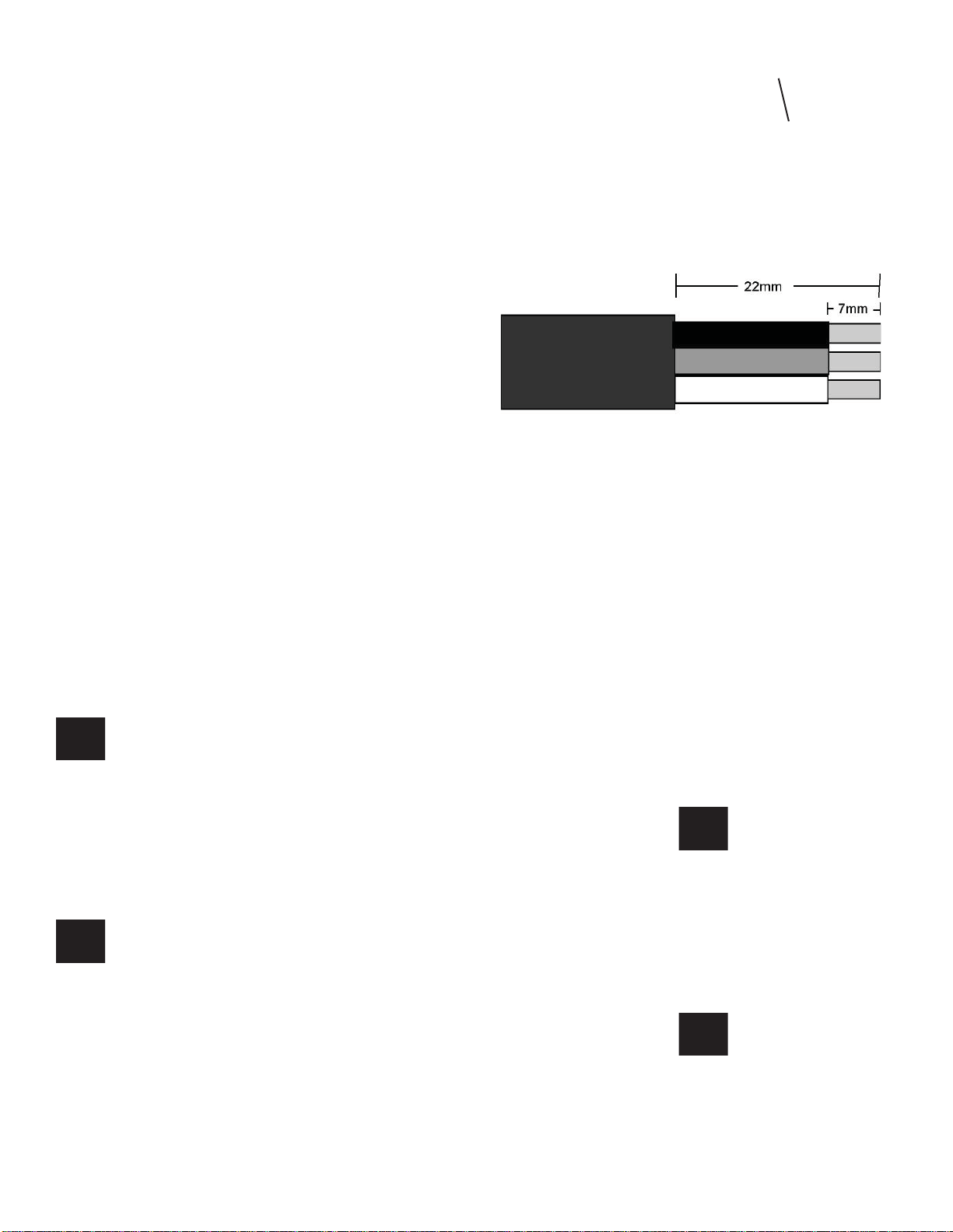
Wire Stripping
STEP FOUR
Insert the stripped wire ends into the terminals on the
back of the Pin/Socket insert and fully tighten the
wire retention screws. (Refer to fi gure for correct wire
orientation).
Single phase wiring:
Figure 5:
Wire Connections
Brown wire to terminal L
Blue wire to terminal N
Green/Yellow wire to terminal E
3 phase wiring:
STEP TWO
Remove the gland nut and gland from the rear of the
housing and slide on to the cable. Make sure the gland
is orientated with the stepped edge facing the gland
nut (see picture).
Stepped Edge
STEP THREE
Prepare the cable and strip wire ends as shown.
Figure 6:
Wire Connections
Brown wire to terminal 1
Black wire to terminal 2
Grey wire to terminal 3
Green/Yellow wire to terminal E
After the wires have been connected securely, pull the
cable and insert back into the housing and tighten with
a screwdriver to ensure the insert is seated correctly.
Note: LEFT HAND THREAD, turn the insert counter
clockwise to tighten.
STEP FIVE
Prepare your supplied Resin Kit by removing the cap
from the resin tube and pushing the resin nozzle onto
the tube. Then twist the nozzle to lock in place.
Wire Stripping
3
nect and insert the sealing cover into the large blue nut
half and tighten fi rmly.
Plunger Resin Tube Nozzle
Before applying to the quick disconnect, use the
plunger to evenly push out a small amount of resin to
get a proper mix of of the 2-part epoxy. Then apply
resin into the housing, enough to cover the wires and
contacts. The resin should be about 3mm onto the
cord jacket. Note: Adding too much resin may cause
excess to be forced into the female end of the pin
connector, preventing proper connection of the two
halves.
Cut-Away
disconnect shown
with clear resin.
Note amount that
is covering cord
Strain Relief
The Strain Relief must be installed to protect the
Quick Disconnect from damage due to excessive
strain. The Strain Relief should be installed on the
user supplied cord length (not on the Kasco supplied
stub cord). It should be position about 15cm from the
Quick Disconnect. To install, insert the narrow end of
the elongated clamp with the chain connected into the
wide end of the short clamp. Use a rubber mallet to
tap the two pieces together securely. A Nylon Tie can
be used to keep it attached to the cord. The chain can
then be attached to the fl oat.
Wire Sizing & Gland Sizing
STEP SIX
Slide the gland and gland nut along the cable into the
body and tighten the gland nut securely. No drying
time is needed for the epoxy before full assembly.
STEP SEVEN
Once the two subassemblies have been completed,
they can be joined together. Plug pin assembly into
the socket assembly and tighten the large blue nut
securely. The blue nut should be hand tightened only.
(See fi gure below).
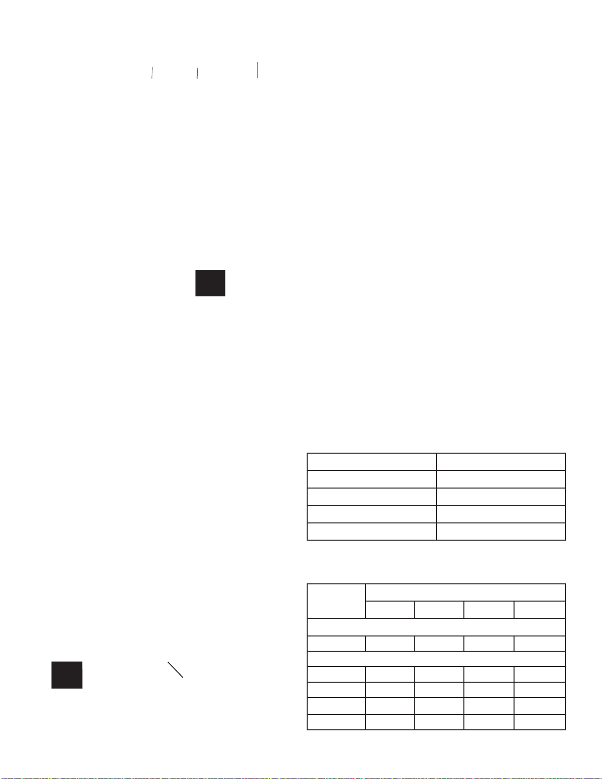
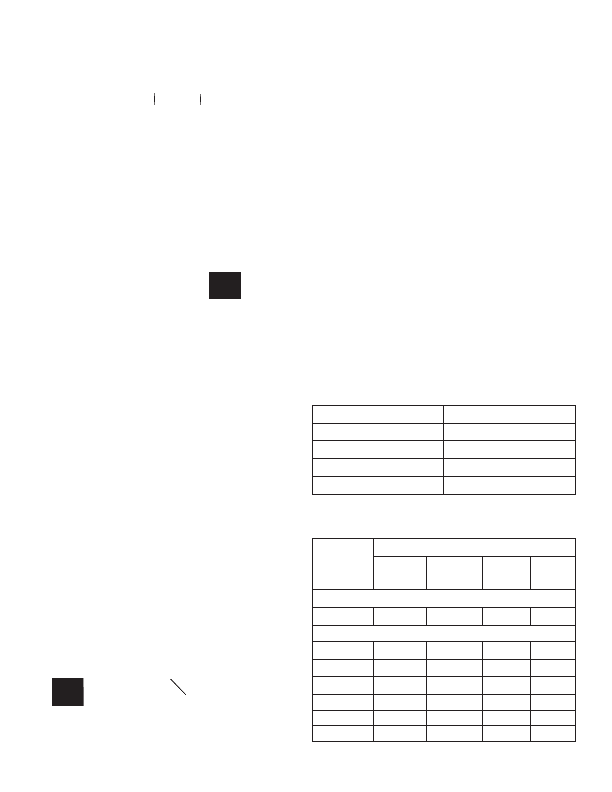
The chart below shows the proper Gland to be used
with different cord sizes. The measurements are based
on the Outside Diameter (O.D.) of the cord. Smooth,
round cords should be used. (HAR H07RN-F)
Kasco Quick Disconnect 50 Hz Size Chart:
Gland O.D. of Cord
Grey 7-9mm
White 9-11mm
Black 11-13mm
Yellow 13-15mm
Kasco 50 Hz Equipment Wire Size Chart
Model Cord Length
10m 30m 60m 90m
8400EJ 1.5mm22.5mm
2
4mm
2
6mm
2
Note: There is a small gap after tightening
For sea- sonal removal, your quick disconnect includes an optional
water tight cover. Simply separate the quick discon-
4
3.1EVX 1.5mm22.5mm
3.1EJ 1.5mm22.5mm
2.3EJ 2.5mm22.5mm22.5mm
2
6mm
2
6mm
2
2
2
6mm
6mm
4mm
2
2
2
Model Cord Length
10m 30m 60m 90m
4mm
2
2
2
3.3EVX 2.5mm22.5mm
3.3EJ 2.5mm22.5mm
5.3EJ 2.5mm
2.3EHJ 2.5mm22.5mm22.5mm
3.3EHVX 2.5mm22.5mm22.5mm
3.3EHJ 2.5mm22.5mm22.5mm
5.3EHJ 2.5mm22.5mm22.5mm
2
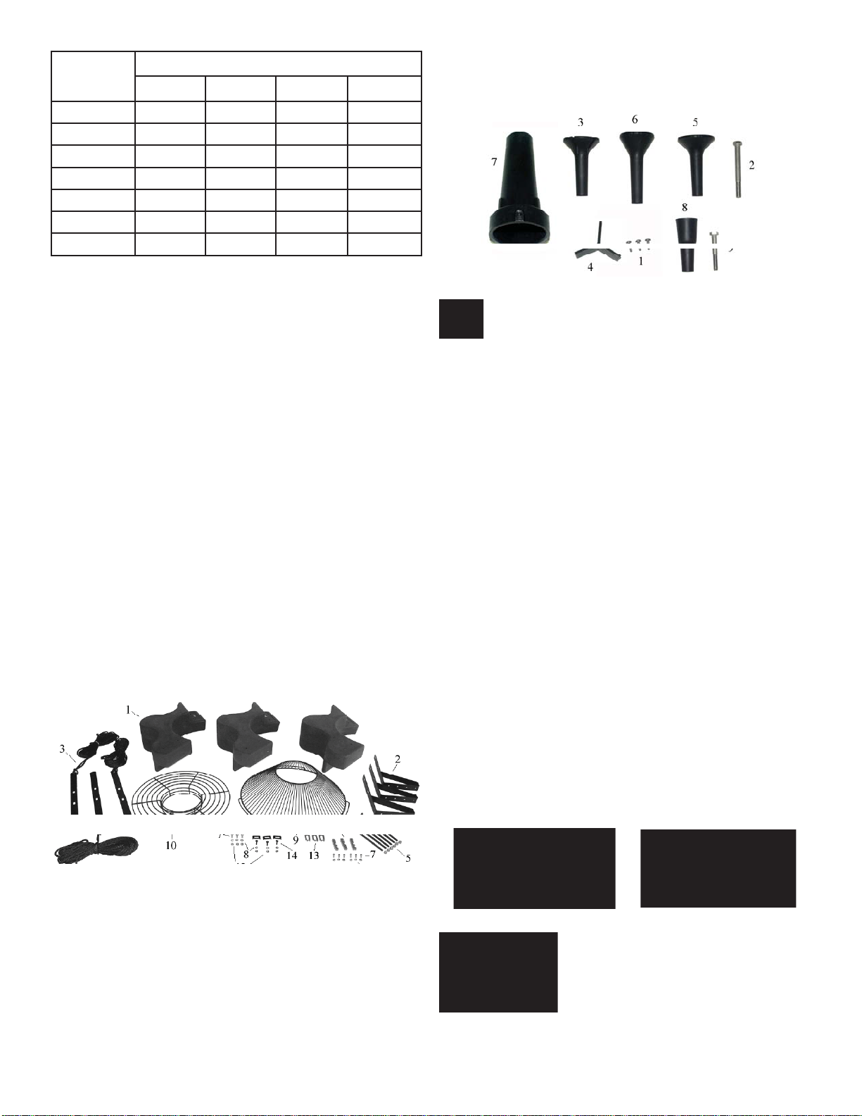
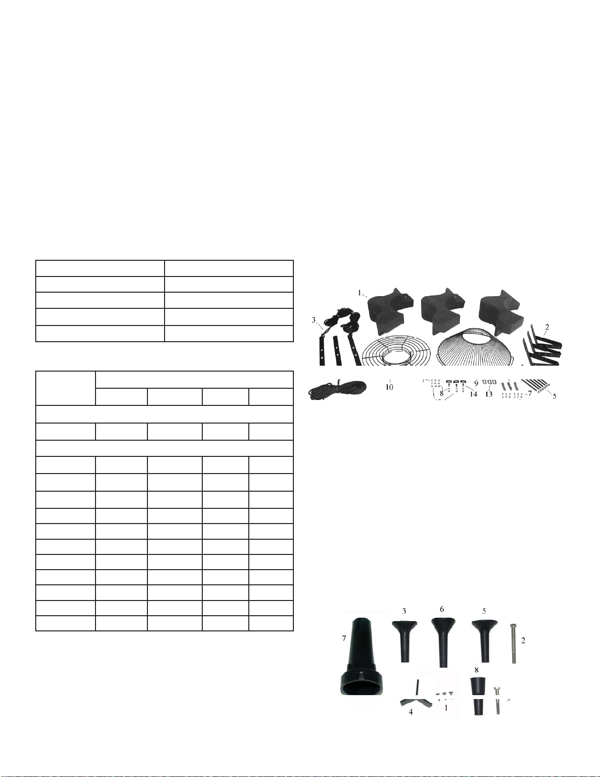
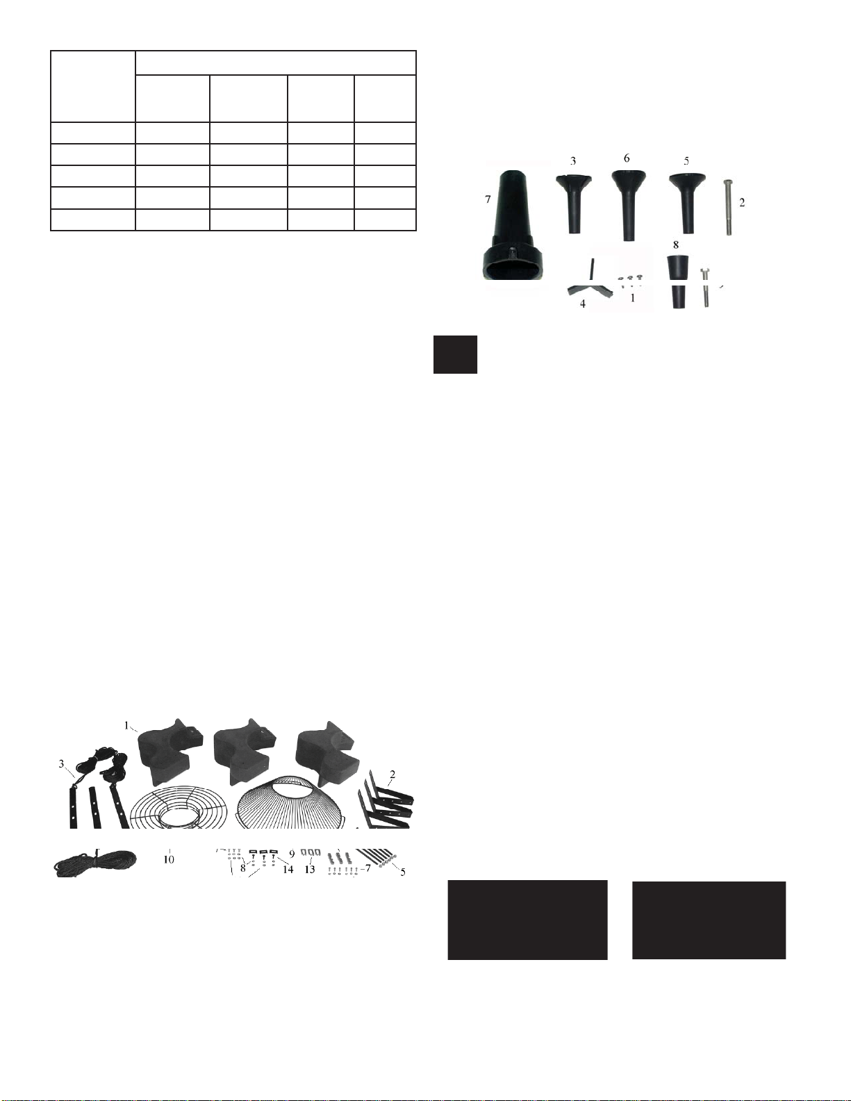
Parts Included
INCLUDED
A. Aerating Fountain (Unit with stub cord) (1)
B. Float in separate box (1)
1. Float Section (3)
2. Top Float Bracket (3)
3. Bottom Float Bracket w/ 50’ rope (3)
4. 9” x 3/8” Black Coated Bolt (6)
5. 3/8” Lock Nut (9)
6. Unit Mounting Bracket (3) (not in
cluded with 3.1EVFX, 5.1EJF)
7. 1/4” x 3/4” Bolt (6)
8. 1/4” Lock Washer (9)
9. Bottom Screen (1)
10. Top Screen (1)
11. Top Screen Clip (3)
12. 1/4” Nut (6)
13. Bottom Screen Clips (3)
14. 1/4-20 x 3/4” Brass Screw (3)
15. 3/8” x 1” Bolt (3)
16. 3/8” Lock Washer (3) (5.3 only)
4mm
4mm
6mm
2
2
2
2
2
2
2
6mm
6mm
6mm
2.5mm
2.5mm
2.5mm
2.5mm
2
2
2
Redwood & Spruce Nozzle (1)7.
Sequoia Nozzle (3.1EJF only)8.
3/8” x 2.5” Bolt (1) (3.1EJF only)9.
2
2
2
2
Note: Extra hardware may be included.
TOOLS & SUPPLIES NEEDED
A. Anchors or stakes for installing unit (3)
B. 240V Electrical Supply near pond on a post
C. Three 30cm pieces of 2.54cm galvanized pipe for
weighting ropes (optional)
D. 7/16” (11mm) Socket & Wrench (1)
E. 7/16” (11mm) Wrench (1)
F. 9/16” (14mm) Socket & Wrench (1)
F. 9/16” (14mm) Wrench or adjustable crescent
wrench (1)
G. Flat head screw driver (1)
Assembly Instructions
STEP ONE
Remove all contents from package and place on a
clean, fl at surface. Inspect the shipment for any dam-
ages. Make sure you have all the parts needed.
C. Set of Five Interchangeable Nozzles (5)
#6 x 1/2” Phillip Pan Head Self Tapping Screw (3)1.
3/8” x 4” bolt (1)2.
Linden Nozzle (1)3.
Redwood Nozzle Y Insert (comes installed in #7)4.
(1)
Juniper Nozzle (1)5.
Willow Nozzle (1)6.
STEP TWO
Arrange the three Float Sections (Part B1) upright
(plug on bottom) so the overlap of one section aligns
with the next section and loosely push the three sections together to form a continuous ring.
Float up
Float down
(plug)
5

STEP THREE
Position one Top Float Bracket (Part B2) so that the
bolt holes in the bracket align with the bolt holes in
the two adjoined fl oat sections and insert two 9” Black
Coated Bolts (Part B4) through the assembly. This
may require some minor repositioning of the fl oat sec-
tions as you push the bolt all the way through. Do not
force the bolt through. Repeat for the remaining two
joints.
STEP FOUR
Turn the assembly upside down and place the Bottom
Float Brackets (Part B3) over the bolts, the ends of
which should now be extending through the assembly.
Loosely install the six Lock Nuts (Part B5) on the ends
of the bolts (do not tighten yet).
Housing, you can use a screwdriver to gently pry open
enough space.
STEP FIVE (for 5.3E(H)JF)
Rest the fl oat on the base plate of the unit. Connect
the fl oat to the base plate using the 3/8” x 1” bolt (Part
#B15) and 3/8” lock washer (Part #B16). Tighten using a 9/16” wrench.
(For 8400, 2.3, 3.1, 3.3)
Connect the top and bottom brackets using three 3/8”
x 1” Bolts (Part B15) with the three 3/8” Nuts (Part
B5) and tighten using the 9/16” (14mm) wrench and
socket.
STEP FIVE (For 8400EJ, 2.3EJ & 3.1EJ, 3.3EJ)
Return the assembly to the upside down position and
place the motor assembly (Stainless Steel can side
up, black pump down) in the center of the fl oat. At-
tach the motor to the fl oat using the Unit Mounting
Brackets (Part B6). The notch in the center of the Unit
Mounting Brackets should be positioned over the top
ring of the cage and should be attached to the fl oat
bracket using the two middle holes of the fl oat bracket
on 8400EJ & 3.1EJ.
STEP FIVE (For 3.1EVFX, 3.3E(H)VFX models)
Return the assembly to the upside down position and
place the motor assembly (Stainless Steel can side
up, black tube down) in the center of the fl oat. Align
the 3 taller legs of the black fountain tube with the 3
fl oat brackets. Attach the motor to the fl oat using the
1/4” x 1” bolts. Attach to the fl oat bracket using the
two middle holes of the fl oat bracket. Tighten us-
ing the 1/4” x 1” Bolts with 1/4” Lock Washers using
the 7/16” socket and wrench. The 1” bolts will screw
directly into the legs of the black fountain tube.
Tighten using the 1/4” x 3/4” Bolts with 1/4” Lock
Washers using the 7/16” socket and wrench. (See pictures) Note: If you have trouble positioning the Unit
Mounting Bracket between the Cage and Fountain
6

STEP SIX
Center the Top Screen (Part B10) inside the three Top
Float Brackets. Attach the screen by spanning each
Top Screen Clip (Part B11) across the two innermost
rings on the screen and the hole in the fl oat bracket.
Insert the Brass Screws (Part B14) and attach with
1/4” Lock Washers and 1/4” Nuts to secure the screen
to the fl oat assembly.
STEP SEVEN
Position the Bottom Screen (Part B9) over the fl oat so
the motor housing (can) passes through the large hole
in the center of the screen. Remove the center three
Lock Nuts from the 9” Bolts and place the Bottom
Screen Clips (Part B13) over the bolts as shown. The
power cord can be slid under the bottom screen where
two fl oat sections come together before the Lock Nuts
are replaced. Replace the three inside Lock Nuts and
tighten all 3/8” Lock Nuts using the 9/16” (14mm)
wrench and socket.
To install the Redwood nozzle, make sure the Y Insert
(Part D4) is installed and seated properly into the
nozzle. Push the nozzle down over the cone assembly
(it may require light taps with a rubber mallet to seat
properly). Next, use the 3 Self Tapping Screws (Part
D1) provided in the 3 holes on the nozzle and tighten
the screws into the cone assembly. Once you feel
resistance, two more turns will be suffi cient. To install
the Spruce nozzle, follow the same steps, but do not
install the Y Insert.
STEP NINE
The power cord should now be attached to the stub
cord by lining up the male and female halves of the
disconnect and hand tightening the blue collar. On
these cords, the Additional Strain Relief should be
attached to one of the lower fl oat brackets as pictured.
If there is not Strain Relief, use the Nylon Cable Tie
provided to secure the cord to a rope to prevent damage by the propeller. If installing a new Quick Disconnect, please refer to Quick Disconnect instructions.
Note: Extra hardware may be included
STEP EIGHT
Return the unit to its upright position and select a
nozzle (See Nozzle and Pattern Options). Select the
proper Shaft Bolt (Part D2) and insert the Shaft Bolt
into the Nozzle Head so it fi ts snugly into the molded
socket. Install the Nozzle by threading it into the inner
cone of the pump. Make sure to tighten the Nozzle all
the way down.
EVX Pattern Size Chart
V-shaped display.
Model Height Width
3.1EVX,
2.0 m 7.3 m
3.3EVX
7
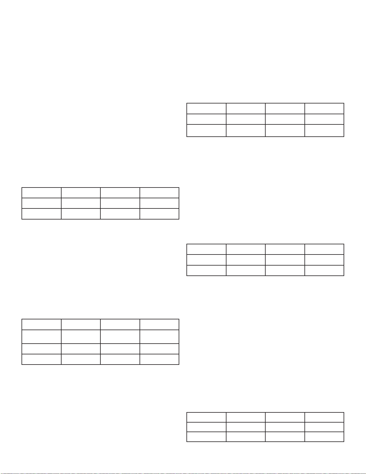
J Nozzle Options
NOTE: Pattern sizes listed are approximate. Variations in voltage caused by regional electrical differences or voltage drop due to long power cords may result
in reduced pattern sizes.
The Redwood nozzle uses the 3 self tapping screws to
attach over the pump housing and the Y Insert must be
installed.
Model HP Height Width
The Willow nozzle (marked W on the inside of the
cone) uses the 3/8” x 4” bolt.
Model HP Height Width
8400, 2.3 2 3.4 m 10.4 m
3.1, 3.3 3 3.6 m 8.2 m
The Juniper nozzle (marked with J on in inside of the
nozzle cone) uses the 3/8” x 4” bolt.
8400, 2.3 2 5.5 m 1.5 m
3.1, 3.3 3 6.1 m 0.9 m
The Linden nozzle (marked L inside one of the fi ns)
uses the 3/8” x 4” bolt.
Model HP Height Width
8400, 2.3 2 4.7 m 10.4 m
3.1, 3.3 3 4.1 m 9.8 m
5.3 5 4.9 m 8.5 m
Model HP Height Width
8400, 2.3 2 1.8 m 13.4 m
3.1, 3.3 3 2.7 m 12.2 m
The Spruce nozzle uses the three self tapping screws
to attach over the pump housing and the Y Insert must
be removed.
Model HP Height Width
8400, 2.3 2 5.5 m 3 m
3.1, 3.3 3 5.8 m 2.1 m
8

The Birch display does not use a nozzle or bolt. It is
the fountain unit running without any nozzle and allows for the best fl ow rate and oxygen transfer!
marked value or the service factor amperes, shown on
the namplate.
3 phase
190 volt
Full load
amps
2.3EJ 3.3EJ 3.3EVX 5.3EJ
6.4 10 9.6 15.2
Model HP Height Width
8400, 2.3 2 3.5 m 1.8 m
3.1, 3.3 3 3.0 m 4.0 m
5.3 5 3.0 m 3.0 m
The Sequoia nozzle (marked S on the inside of the
cone) uses the 3/8” x 2.5” bolt.
3.1EJF, 3.3E(H)JF, 5.3E(H)JF ONLY
Model HP Height Width
3.1, 3.3 3 4.6 m 3.0 m
5.3 5 5.8 m 3.0 m
3 Phase Startup Procedure
A Control Panel is not provided with your unit, please
refer to the following warnings:
When inherent overheating protection is not provided:
use with approved motor control that matches motor
input in full load amperes with overload element(s)
selected or adjusted in accordance with control
instructions.
Proper ground fault protection (RCD) must be
provided at time of installation in your control panel
Note: The motor input in full load amperes is the
3 phase
380 volt
Full load
amps
2.3HEJ 3.3HEJ 3.3HEVX 5.3EHJ
3.3 5 4.8 7.7
Control panels must be installed by a qualifi ed
electrician.
If unit is connected to a circuit protected by a fuse, use
a time-delay fuse with this pump.
You must verify motor rotation before installing
the unit in the water.
3phase Kasco units will run in a clockwise rotation
when looking down at the propeller/impeller. On J
series units the upper pump housing must be removed
to see the propeller/impeller. Stand clear of the
propeller/impeller while verifying rotation. Follow
the steps below.
Electrician:
Verify all screw terminal connections are tightened to 1.
specifi ed torque setting prior to energizing the panel.
Verify the electrical service (voltage and Phase) 2.
matches the control panel and
ratings. Refer to your control panel instructions and
schematics for installation details.
Verify all switches, circuit breakers, and motor starters 3.
are in the OFF position
Connect electrical service to your control panel as 4.
shown in the electrical schematic that came with the
panel.
Connect the unit power cord to the panel as shown in 5.
the electrical schematic with your panel
Set the motor starter overload to the FLA rating on the 6.
aerator nameplates
aerator nameplate.
Pump rotation: Remove the upper pump housing (if 7.
you have a J series
screws attaching it to the lower pump housing. The
pump rotation is clockwise when looking down at the
propeller/impeller. Apply power to the control panel.
Turn on the 15amp control circuit breaker, and motor
starter.
Momentarily turn the Hand-Off-Auto switch to Hand. 8.
aerator) by removing the three
9
This will run the aerator. Do not run the aerator for
more than a few seconds on shore. If the rotation is
not correct. Disconnect and lock out power from the
control panel. Swap any two of the
wires in the panel. This will cause the motor to reverse
direction. Reapply power to the panel and verify the
rotation is clockwise.
Once rotation is verifi ed, with the power disconnected 9.
and locked out again, reinstall the upper pump housing.
Run the
shore to ensure the housing was reinstalled correctly.
Disconnect and lock out power again and continue with
installation of the
owner’s manual.
aerator one more time momentarily on
aerator as detailed in the aerator
aerator power cord
Record the following data while the unit is operating
in the water under load:
Voltage: Amperage:
L1-L2 ____________ L1_______________
L1-L3 ____________ L2_______________
L2-L3 ____________ L3_______________
Current unbalance should not exceed 5% at full load
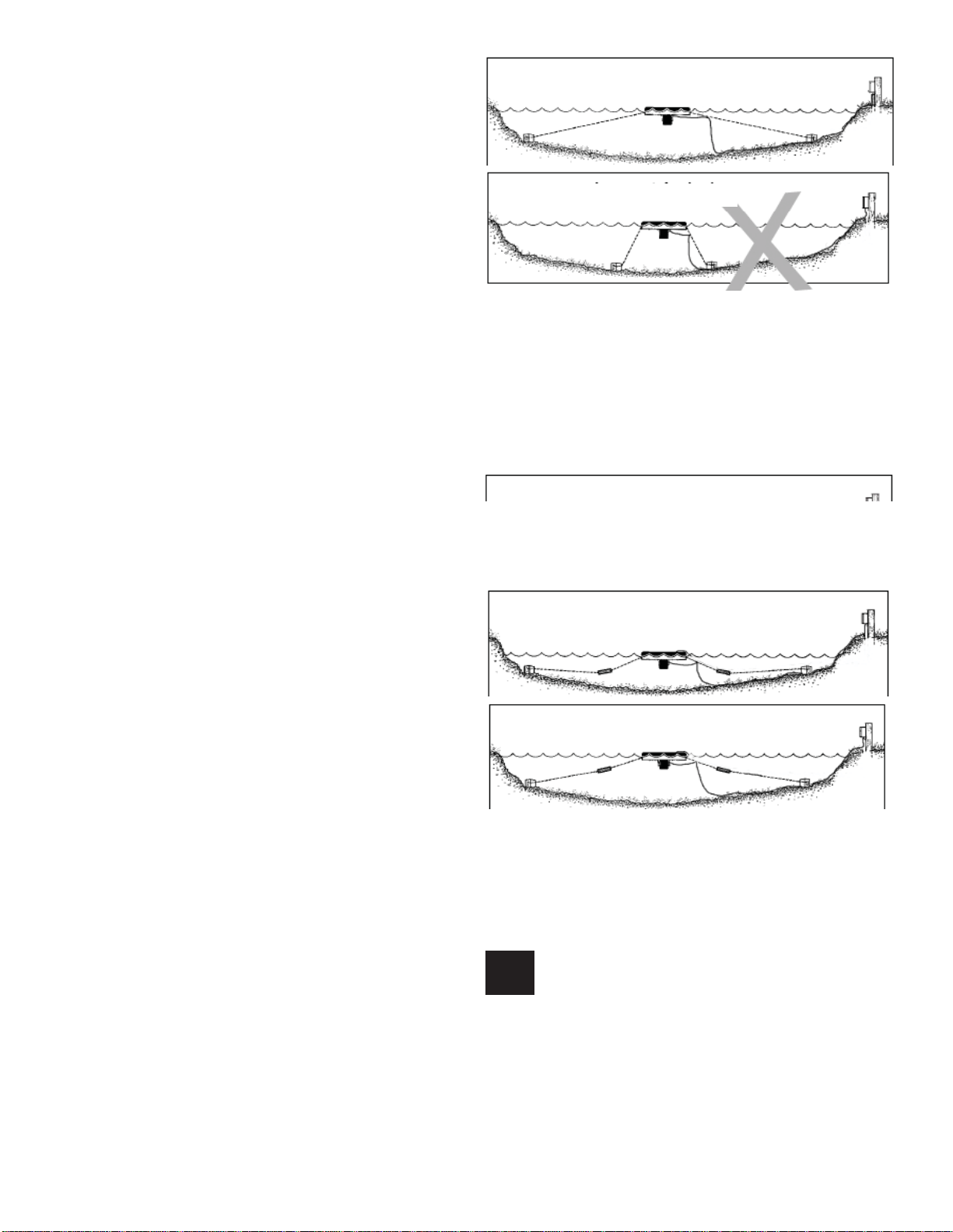
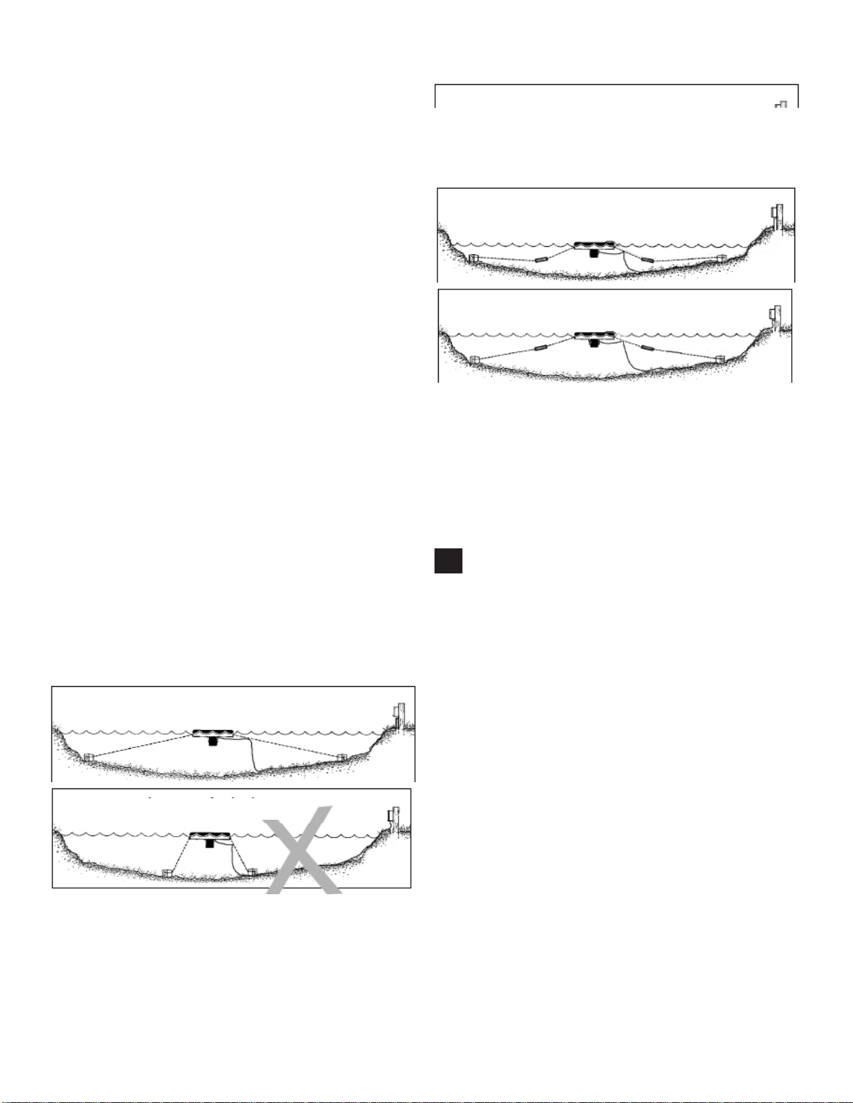
Correct Anchoring
Incorrect Anchoring
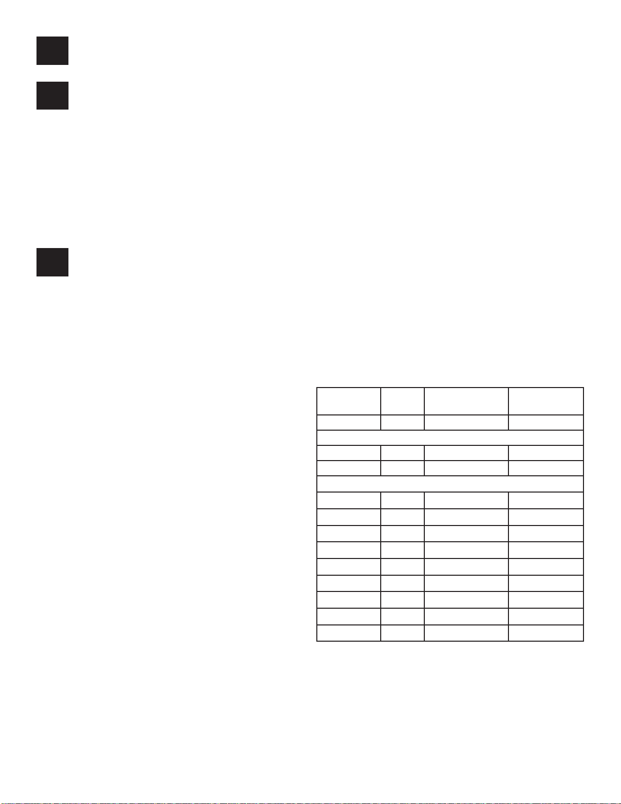
STEP TWO (ALTERNATE INSTALLATION)
In ponds where the water level fl uctuates signifi cantly,
you may need to suspend a small weight (30cm of
2.54cm galvanize pipe works well) at the mid-point of
the rope to take up any slack as the water level drops.
The weight should be light enough so the Unit can rise
as the water level rises. This can also help hide ropes
by sinking them further below the surface.
Normal W ater level
Anchor Rope
Secondary Weight
Low W ater Level
Power Cord
Kasco Power
Control Box
Installation Instructions
STEP ONE
Use the ropes to position the Unit in the desired location in the pond/lake (secure the cord near power
source to prevent it from being dragged into the water). Anchor the ropes or secure them to the shoreline
so the ropes are free of slack, but not tight. To prevent
twisting of the unit due to torque, you should place
the anchor at least 3m from the fl oat for each meter of
depth (Ex. A 3m deep pond would require an anchor
9m horizontally from the fl oat.) For ease of removal,
you may choose to keep at least one anchor within
reach from shore, just below the water’s surface.
High W ater Level
STEP THREE
At this time the Fountain is ready for operation. It can
be plugged into the power supply at the pond edge.
ENJOY YOUR NEW KASCO EQUIPMENT!
Maintenance Recommendations
Under No Circumstances should anyone enter
the water while a unit is operating. Turn Off and Disconnect electrical power prior to any Maintenance or
Servicing
RCD (Residual Current Device) or GFCI are a safety
feature that can also alert you to electrical leaks in the
equipment. It is extremely important to test the RCD
upon installation, each reinstallation, and monthly
10

thereafter to ensure proper operation. If you have repeat, consistent trips on your ground fault (RCD), the
equipment should be disconnected and removed from
the water. The power cord should be inspected for
damage and you should call a Kasco Marine distributor or representative for further instructions.
longevity to the operation of the motor, saving you the
cost of more expensive repairs. In warmer climates
where the equipment runs most or all of the year, it is
a good idea to replace seals more regularly than you
would need to in colder climates where the unit is
removed from the water for several months.
If the supply cord becomes damaged, it must be
replaced by an authorized service center, or similarly
qualifi ed persons in order to avoid a hazard.
OBSERVATION: Operating equipment should be
observed on a regular basis (daily, if possible) for any
reduction or variation in performance. If a change in
performance is observed, the equipment should be disconnected from power and inspected for any material
that may have clogged the system or wrapped around
the shaft of the motor, especially plastic bags and fi sh-
ing line. Even though Kasco Fountains are among the
most clog-resistant on the market, it is impossible to
protect against all items that can clog equipment and
still maintain a fl ow of water. These materials can
be very damaging to the equipment under continued
operation and must be removed as soon as possible.
ALWAYS DISCONNECT POWER TO THE UNIT
BEFORE ATTEMPTING TO REMOVE CLOGS.
WINTER STORAGE: In regions where there is signifi cant freezing in the wintertime, Fountains should
be removed from the water to protect them from the
expansion pressure of the ice. Storage over winter is
best in a location that is out of the sun and cool, but
O
above 0
C.
ZINC ANODE: A Sacrifi cial Zinc Anode is supplied
on the shaft of all Kasco 50Hz Fountains for protection of the equipment from corrosion and electrolysis. The zinc anode should be updated (replaced) if
reduced to half the original size or if white in color.
Corrosion from electrolysis is more commonly associated with saltwater or brackish water, but as a matter
of precaution, it is important to periodically check the
zinc anode in all installations (at least every two to
three months).
Seal replacement and all other repair services should
be performed by Kasco Marine or a Kasco trained
Authorized Repair Center. Please contact your Kasco
Marine, Inc. distributor or representative for your
nearest Authorized Repair Center.
Troubleshooting Tips
For more tips and information contact your Kasco
distributor or go to
www.kascomarine.com (Under the technical tab)
CLEANING: Equipment should be removed from the
water at least once per year (at the end of the season
in cold climates) to clean the exterior of the system,
especially the stainless steel motor housing (can). The
motor housing is the surface that dissipates heat into
the water and any algae, calcium, etc. build-up will become an insulator that blocks heat transfer. In warmer
regions it is recommended that the motor is removed
and cleaned at least two to three times per year depending on conditions. In most cases a power washer
will be suffi cient if the unit and algae are still wet.
SEAL AND OIL REPLACEMENT: This is a sealed
motor assembly and seals will wear out over time
(similar to brake pads on a car). Replacement of the
seals and a change of oil after three years may add
Kasco Marine, Inc.
800 Deere Rd.
Prescott, WI 54021
U.S.A.
Phone 00+1+715+262+4488
Fax 00+1+715+262+4487
www.kascomarine.com
sales@kascomarine.com
service@kascomarine.com
#884152
11


Gebruikershandleiding
50 Hz-fonteinen
8400EJ, 3.1EJ, 3.1EVX
2.3E(H)J, 3.3E(H)J, 3.3E(H)VX, 5.3E(H)J
Inhoudsopgave
Belangrijke veiligheidsaanwijzingen . . . . . .2
Specifi caties van de units . . . . . .2
Installatie van de ‘Quick disconnect’-aansluiting . . . . . .2
Maten van draad en wartels . . . . . .5
Bijgeleverde onderdelen . . . . . .5
Montage-instructies . . . . . .6
Tabel met de afmetingen van EVX-patronen . . . . . .8
Sproeieropties voor model JF . . . . . .8
Opstartprocedure 3-fasige units . . . . . .10
Installatieinstructies . . . . . .11
Aanbevolen onderhoud . . . . . .11
Tips voor het oplossen van problemen . . . . . .12
Kasco Marine, Inc.
800 Deere Rd.
Prescott, WI 54021
VS
Tel.: +1-715-262-4488
Fax: +1-715-262-4487
sales@kascomarine.com
www.kascomarine.com
Herz. 07/10/08
LET OP
KENNISGEVING (OPMERKING)
Deze internationale veiligheidssymbolen worden
overal in deze handleiding gebruikt om de eigenaar
attent te maken op belangrijke veiligheidsinformatie
en kennisgevingen in verband met het veilige en
doeltreffende gebruik van de apparatuur.
Belangrijke
veiligheidsaanwijzingen
LET OP
Personen mogen zich NOOIT in het water •
bevinden terwijl de elektrische apparatuur
aangesloten en/of in werking is. Het is NOOIT
verstandig om het water in te gaan terwijl de
apparatuur in werking is.
Ga altijd uiterst voorzichtig te werk tijdens •
het hanteren van elektrische apparatuur met
bewegende onderdelen.
Laat de unit NOOIT buiten het water draaien. •
Hierdoor worden de afdichtingen beschadigd en
wordt een gevaarlijke situatie geschapen voor
de operator.
Wees uiterst voorzichtig in de buurt van water, •
vooral koud water, bijv. in de lente, herfst en
winter, wat op zich al een gevaarlijke situatie is.
De unit mag NOOIT aan het stroom- of •
lichtsnoer worden opgetild of voortgetrokken.
Als u de unit naar de zijkant van de vijver
moet trekken, gebruik hiervoor dan de
verankeringskabels.
Gebruik nooit lieslaarzen in vijvers of meren •
die diep zijn, plotseling aanzienlijk dieper
worden of een sterk hellende bodem hebben of
een bodem die uit zacht materiaal bestaat.
Gebruik tijdens de installatie van uw •
fontein nooit een boot die gemakkelijk kan
omslaan (zoals een kano) en volg alle regels
en voorschriften voor veiligheid op het water,
inclusief het dragen van een reddingsvest
(‘Personal Flotation Device’ of ‘PFD’).
De unit wordt geleverd met een interne •
aardleiding. Om het risico van elektrische
schokken te verminderen, dient u ervoor
te zorgen dat de unit op een goedgekeurde
stroomketen met aardlekschakelaar
(verliesstroomautomaat) wordt aangesloten.
Bij de installatie moet een 3-fasige •
motorbesturing (starter) van de juiste grootte
met beveiliging tegen overbelasting en
kortsluiting beschikbaar zijn.
Bij 3-fasige beluchters (2.3, 3.3, 5.3) is na de •
bedrading een opstarttest nodig ter controle van
de juiste draairichting van de rotor. Als de rotor
de verkeerde kant op draait, werkt de unit niet
naar behoren, wat tot interne schade kan leiden
(zie Opstartprocedure 3-fasige units).
De vaste bedrading moet voorzien zijn •
van een ontkoppelingssysteem, dat aan
zowel de plaatselijke als de nationale
bedradingsvoorschriften voldoet; dit om
onbedoeld opstarten te voorkomen.
Raadpleeg een bevoegd elektricien voor de •
elektrische installatie.
Specificaties van de units
Model Voltage Bedrijfs-stroom-
sterkte
3.1EVX 208-240 12,5@220V 60@220V
8400EJ 208-240 9,5@220V 40@220V
3.1EJ 208-240 13,2@220V 60@220V
3.3EVX 190 9.6 69
2.3EJ 190 6.4 41
3.3EJ 190 10 69
5.3EJ 190 15.2 98
3.3EHVX 380 4.8 34
2.3EHJ 380 3.3 21
3.3EHJ 380 5 34
5.3EHJ 380 7.7 49
Initiële
aanloopstroom
Installatie van de ‘Quick
disconnect’-aansluiting
Belangrijk – vóór de installatie aandachtig lezen
Alvorens met de installatie van de connector te
beginnen, dient u deze instructies aandachtig te lezen
2
en te begrijpen, zodat u het connectorsysteem volledig
waterdicht en elektrisch veilig kunt installeren. IN
GEVAL VAN TWIJFEL DIENT U EEN BEVOEGD
ELEKTRICIEN TE RAADPLEGEN.
De contrastekker (het vrouwelijke deel) van de
connector hoort rechtstreeks op de stroomvoorziening
aangesloten te zijn. De stekker (het mannelijke deel)
van de connector hoort aan het te voeden apparaat
vast te zitten. 50 Hz-units worden af fabriek geleverd
met de stekker (het mannelijke deel) van de connector
geïnstalleerd. Een goede afdichting is alleen mogelijk
als er gladde, ronde kabel wordt gebruikt.
Stekker van de connector (af fabriek geïnstalleerd
op het korte snoer)
Trapvormig uiteinde
STAP 3
Maak de kabel klaar door de draaduiteinden te
strippen zoals afgebeeld.
Strippen van de draden
Stekker
Wartel
Behuizing
Wartelmoer
Contrastekker (door gebruiker geïnstalleerd)
Contrastekker
Wartel
Behuizing
Wartelmoer
Opmerking:
Witte wartel voor buitendiameter van 9-11 mm
Gele wartel voor buitendiameter van 13-15 mm
Instructies voor samenstelling/bedrading
Verwijder de contrastekker uit de behuizing van de
connector. In het midden van de contrastekker zit een
sleuf voor een platte schroevendraaier.
Strippen van de draden
STAP 4
Steek de gestripte draaduiteinden in de contacten
achterop de contrastekker en draai de schroeven
volledig aan (zie afbeelding voor de juiste plaatsing
van de draden).
Bedrading enkelfasige units:
Afbeelding 5:
Aansluitingen van de draden
Bruine draad -- contact L
Blauwe draad -- contact N
Groen/gele draad -- contact E
Opmerking: de stekker en de contrastekker
hebben LINKS SCHROEFDRAAD; dus RECHTSOM
draaien om te verwijderen.
STAP 2
Haal de wartelmoer en de wartel uit de achterkant
van de behuizing en breng deze (de wartelmoer en de
wartel) op de kabel aan. Het trapvormige uiteinde van
de wartel moet naar de wartelmoer gericht zijn (zie
afbeelding).
Bedrading 3-fasige units:
Afbeelding 6:
Aansluitingen van de draden
Bruine draad -- contact 1
Zwarte draad -- contact 2
Grijze draad -- contact 3
Groen/gele draad -- contact E
3

Trek nadat u de draden juist hebt aangesloten, de kabel
met de contrastekker erop weer in de behuizing en zet
de contrastekker met een schroevendraaier stevig vast.
Opmerking: LINKS SCHROEFDRAAD; draai
de contrastekker dus LINKSOM vast.
STAP 5
Maak de bijgeleverde harsset klaar door het dopje van
het harsbuisje te verwijderen en het tuitje op het buisje
aan te brengen. Draai het tuitje vervolgens totdat het
vastklikt.
Plunjer Buisje met hars Tuitje
Druk alvorens de hars op de ‘Quick disconnect’aansluiting aan te brengen, de plunjer gelijkmatig
voldoende in om een kleine hoeveelheid hars te
spuiten; dit is nodig om de uit 2 componenten
bestaande epoxyhars naar behoren te mengen. Breng
vervolgens voldoende hars in de behuizing aan om de
draden en de contacten te bedekken. De hars moet
ongeveer 3 mm van de kabelmantel bedekken.
Opmerking: als er teveel hars wordt aangebracht, kan
het overschot in de contrastekker worden geperst,
waardoor de stekker er niet goed in zou passen.
Opengewerkte
afbeelding van
het vrouwelijke
gedeelte van de
‘Quick disconnect’aansluiting met
kleurloze hars. Let
op de hoeveelheid
hars op de
kabelmantel.
STAP 6
Schuif de wartel en de wartelmoer langs de kabel in de
behuizing en draai de wartelmoer stevig vast. Hiervoor
is het niet nodig de epoxyhars eerst te laten drogen.
STAP 7
Wanneer deze helft van het ontkoppelingssysteem
klaar is, kunnen de twee helften op elkaar worden
aangesloten. Steek de stekker in de contrastekker en
draai de grote blauwe moer stevig vast. De blauwe
moer moet met de hand worden vastgedraaid. Zie de
onderstaande afbeelding.
Opmerking: nadat de blauwe moer is vastgedraaid,
is er hier een kleine ruimte zichtbaar
Als dit bij verwijdering aan het einde van het seizoen
gewenst is, kan de ‘Quick disconnect’-aansluiting
worden beschermd met de bijgeleverde waterdichte
afdekking. Maak hiervoor de ‘Quick disconnect’aansluiting los en breng de afdekking in de helft met
de grote blauwe moer aan. Draai deze vervolgens
stevig vast.
Trekontlasting
De trekontlasting is nodig om de ‘Quick disconnect’aansluiting te beschermen tegen beschadiging door
overmatige trekkracht. De trekontlasting moet op
het door de gebruiker verzorgde snoer worden
geïnstalleerd (niet op het door Kasco geleverde
korte snoer met de stekker). De trekontlasting moet
ongeveer 15 cm van de ‘Quick disconnect’-aansluiting
worden gemonteerd. Steek hiervoor het smalle
uiteinde van de lange klem met de ketting eraan
in het brede uiteinde van de korte klem. Gebruik
een rubberen hamer om deze twee stukken stevig
aan elkaar te bevestigen. Het geheel kan met een
nylon kabelbinder aan het snoer worden bevestigd.
Vervolgens kan de ketting aan het drijfl ichaam worden
bevestigd.
4
Maten van draad en wartels
De onderstaande tabel toont de wartels die met
verschillende snoermaten moeten worden gebruikt.
Deze maten zijn gebaseerd op de buitendiameter
van het snoer. Alleen glad, rond snoer moet worden
gebruikt.
Tabel met maten voor de Kasco 50 Hz-’Quick
disconnect’-aansluiting:
Wartel Buitendiameter snoer
Grijs 7-9mm
Wit 9-11mm
Zwart 11-13mm
2. Beugel voor bovenop drijfl ichaam (3)
3. Beugel voor onderop drijfl ichaam met 15 m (50 ft)
lange kabel (3)
4. Zwart gecoate bout van 9 x 3/8 inch (229 x 9,5 mm)
(6)
5. Borgmoer van 3/8 inch (9,5 mm) (9)
6. Montagebeugel voor de motor (3) (niet bijgeleverd
bij model 3.1EVFX, 3.3EVX, 5.3EJF)
7. Bout van 1/4 x 3/4 inch (6 x 19 mm) (6)
8. Borgring van 1/4 inch (6 mm) (9)
9. Onderste scherm (1)
10. Bovenste scherm (1)
11. Bevestigingsclip bovenste scherm (3)
12. Moer van 1/4 inch (6 mm) (6)
13. Bevestigingsclips onderste scherm (3)
14. Koperen schroef, 1/4-20 x 3/4 inch (19 mm) (3)
15. Bout van 3/8 x 1 inch (9,5 x 25 mm) (6)
16. Borgring van 3/8 inch (9,5 mm) (9) (5.3EJF)
Geel 13-15mm
Tabel draaddikten Kasco 50 Hz-apparatuur
Model Snoerlengte
10m 30m 60m 90m
8400EJ
3.1EVX
3.1EJ
2.3EJ 2.5mm
3.3EVX 2.5mm
3.3EJ 2.5mm
5.3EJ 2.5mm
2.3EHJ 2.5mm
3.3EHVX 2.5mm
3.3EHJ 2.5mm
5.3EHJ 2.5mm
1,5mm22,5mm24mm26mm
1,5mm22,5mm26mm26mm
1,5mm22,5mm26mm26mm
2
2.5mm
2
2.5mm
2
2.5mm
2
2
2.5mm
2
2.5mm
2
2.5mm
2
2.5mm
4mm
2
2.5mm24mm
2
4mm
2
4mm
2
6mm
2
2.5mm22.5mm
2
2.5mm22.5mm
2
2.5mm22.5mm
2
2.5mm22.5mm
C. Set van vijf verwisselbare sproeiers (5)
2
1. Zelftappende cilinderkopschroef met kruiskop, nr. 6
x 1/2 inch (13 mm) (3)
2
2. Bout van 3/8 x 4 inch (9,5 x 102 mm) (1)
2
3. Sproeier ‘Linden’ (1)
4. Y-vormig inzetstuk sproeier ‘Redwood’ (standaard
geïnstalleerd in nr. 7)(1)
2
2
6mm
2
6mm
2
6mm
5. Sproeier ‘Juniper’ (1)
2
6. Sproeier ‘Willow’ (1)
2
7. Sproeier ‘Redwood’ en ‘Spruce’ (1)
2
8. Sproeier ‘Sequoia’ (alleen bij model 3.1EJF)
2
9. Bout van 3/8 x 2,5 inch (9,5 x 63,5 mm) (1)
2
(alleen bij model 3.1EJF)
2
2
Bijgeleverde onderdelen
BIJGELEVERD
A. Fontein/beluchter (unit met kort snoer) (1)
B. Drijfl ichaam in aparte doos (1)
1. Segment van het drijfl ichaam (3)
5

Opmerking: er is mogelijk extra hardware
bijgeleverd.
BENODIGD GEREEDSCHAP, ENZ.
A. Ankers of staken voor installatie van unit (2)
B. Stroomvoorziening (240 V) nabij vijver, op paaltje
C. Drie 30 cm lange stukken gegalvaniseerde buis
(doorsnede 2,54 cm) voor verzwaring van kabels
(facultatief)
D. Ratelsleutel met dopsleutel, 7/16 inch (11 mm) (1)
E. Sleutel, 7/16 inch (11 mm) (1)
F. Ratelsleutel met dopsleutel, 9/16 inch (14 mm) (1)
F. Sleutel, 9/16 inch (14 mm) of verstelbare
moersleutel (1)
G. Platte schroevendraaier (1)
is het wellicht nodig de plaatsing van de segmenten
van het drijfl ichaam enigszins aan te passen. Forceer
de bout niet. Herhaal deze procedure voor de andere
twee overlappende gedeelten.
STAP 4
Keer het samenstel ondersteboven en breng de beugels
voor onderop het drijfl ichaam (onderdeel B3) op
de bouten aan (de uiteinden hiervan horen nu uit de
onderkant van het drijfl ichaam te steken). Breng de
zes borgmoeren (onderdeel B5) losjes op de uiteinden
van de bouten aan; draai ze nog niet vast.
Montage-instructies
STAP 1
Verwijder de gehele inhoud uit de doos en plaats alles
op een schoon, plat oppervlak. Inspecteer het geheel
op schade. Overtuig u ervan dat u alle benodigde
onderdelen hebt.
STAP 2
Plaats de drie segmenten van het drijfl ichaam
(onderdeel B1) rechtop (plug onderop) zodat de
hiervoor bedoelde gedeelten elkaar naar behoren
overlappen en druk de drie segmenten losjes op elkaar,
zodat deze een ring vormen.
Bovenkant drijfl ichaam
STAP 3
Breng één van de beugels voor bovenop het
drijfl ichaam (onderdeel B2) zodanig aan dat de
boutgaten in de beugel overeenkomen met de
boutgaten in de twee samengevoegde segmenten van
het drijfl ichaam en steek twee zwart gecoate bouten
van 9 inch (229 mm) (onderdeel B4) door het geheel
heen. Terwijl u de bout hier helemaal doorheen duwt,
Onderkant drijfl ichaam
(plug)
(voor de modellen 8400, 2.3, 3.1, 3.3)
Verbind de bovenste en de onderste beugels met
behulp van drie bouten van 3/8 x 1 inch (9,5 x 25 mm)
(onderdeel B15) en drie moeren van 3/8 inch (9,5 mm)
(onderdeel B5) en draai ze vast met de ratelsleutel met
dopsleutel van 9/16 inch (14 mm).
STAP 5
(voor de modellen 8400EJ, 2.3EJ en 3.1EJ, 3.3E(H)J)
Zet de unit weer ondersteboven en breng de
motoreenheid (met de roestvrij stalen cilinder
omhoog en de zwarte pomp omlaag) in het midden
van het drijfl ichaam aan. Bevestig de motor aan het
drijfl ichaam met de hiervoor bedoelde montagebeugels
(onderdeel B6). De uitsparing in het midden van
de montagebeugels voor de motor past over de
bovenste ring van de korf en elke montagebeugel
voor de motor moet in de twee middelste gaten in de
overeenkomstige beugel op het drijfl ichaam worden
bevestigd (bij de modellen 8400EJ en 3.1EJ).
Gebruik hiervoor de bouten van 1/4 x 3/4 inch (6 x 19
mm) en de borgringen van 1/4 inch (6 mm) en draai
deze vast met de ratelsleutel met dopsleutel van 7/16
inch (11 mm) (zie de afbeeldingen). Opmerking: Als
de montagebeugel voor de motor moeilijk tussen de
korf en de behuizing van de fontein past, kunt u hier
6

een schroevendraaier tussen steken en voorzichtig wat
meer ruimte maken.
STAP 5 (voor model 5.3E(H)JF)
Til het drijfl ichaam op en plaats het over de beluchter-
eenheid heen. Breng de bouten van 3/8 x 1 inch (9,5 x
102 mm) (onderdeelnr. B15) en de borgringen van 3/8
inch (9,5 mm) (onderdeelnr. B16) door de bovenste en
de onderste beugel op het drijfl ichaam aan zoals in de
afbeelding te zien is en draai deze rechtstreeks in de
montagering van de beluchter vast. Draai de bouten
aan met een sleutel van 9/16 inch (14,3 mm).
STAP 5 (voor model 3.1EVFX, 3.3E(H)VFX)
Zet de unit weer ondersteboven en breng de
motoreenheid (met de roestvrij stalen cilinder omhoog
en de zwarte buis omlaag) in het midden van het
drijfl ichaam aan. Breng de 3 lange poten op de zwarte
fonteinbuis op één lijn met de 3 beugels op het
drijfl ichaam. Bevestig de motor aan het drijfl ichaam
met de bouten van 1/4 x 1 inch (6 x 25,4 mm).
Bevestig de motor aan de beugel op het drijfl ichaam
via de twee middelste gaten hierin. Gebruik hiervoor
de bouten van 1/4 x 1 inch (6 x 25,4 mm) en de
borgringen van 1/4 inch (6 mm) en draai deze vast met
de ratelsleutel met dopsleutel van 7/16 inch (11 mm).
De bouten van 1 inch passen rechtstreeks in de poten
van de zwarte fonteinbuis.
STAP 6
Zet de unit op zijn zijkant en centreer het bovenste
scherm (onderdeel B10) ten opzichte van de drie
beugels bovenop het drijfl ichaam. Bevestig het scherm
door de 3 bevestigingsclips (onderdeel B11) over de
twee binnenste ringen van het scherm en de gaten in
de overeenkomstige beugels aan te brengen. Breng de
koperen schroeven (onderdeel B14) aan en zet deze
vast met borgringen en moeren van 1/4 inch (6 mm)
om het scherm aan het drijfl ichaam te bevestigen.
STAP 7
Plaats het onderste scherm (onderdeel B9) zodanig
op het drijfl ichaam dat de (cilindervormige)
motorbehuizing in de grote opening in het midden
van het scherm past. Verwijder de binnenste drie
borgmoeren van de bouten van 9 inch (229 mm) en
breng de bevestigingsclips voor het onderste scherm
(onderdeel B13) op de bouten aan (zie afbeelding).
Alvorens de borgmoeren opnieuw te monteren, kunt u
het stroomsnoer onder het onderste scherm schuiven
op het verbindingspunt tussen twee segmenten van
het drijfl ichaam. Breng de binnenste drie borgmoeren
weer aan en draai alle borgmoeren van 3/8 inch (9,5
mm) vast met de ratelsleutel met dopsleutel van 9/16
inch (14 mm).
7
Opmerking: er is mogelijk extra hardware
bijgeleverd.
STAP 8
Zet de unit weer rechtop en selecteer een sproeier
(zie het gedeelte ‘Sproeieropties’). Selecteer de juiste
asbout (onderdeel D2) en breng deze zodanig in de
sproeierkop aan dat hij strak in de hiervoor bedoelde
opening past. Installeer de sproeier door deze in de
binnenste kegel van de pomp te schroeven. Draai de
sproeier geheel vast.
hoort de trekontlasting aan één van de onderste
beugels op het drijfl ichaam te worden bevestigd (zie
afbeelding). Als er geen trekontlasting is, dient u het
snoer met de bijgeleverde nylon kabelbinder aan één
van de kabels te bevestigen om beschadiging door de
propeller te voorkomen. Zie als u een nieuwe ‘Quick
disconnect’-aansluiting gaat installeren het gedeelte
‘Installatie van de ‘Quick disconnect’-aansluiting’.
Tabel met de afmetingen van
EVX-patronen
V-vormig patroon.
Model Hoogte Breedte
3.1EVX 2,0 m 7,3 m
Sproeieropties voor model JF
Alvorens de sproeier ‘Redwood’ te monteren, dient u
zich ervan te overtuigen dat het Y-vormige inzetstuk
(onderdeel D4) aanwezig is en naar behoren in de
sproeier vastzit. Druk de sproeier op de kegelvormige
eenheid vast (hiervoor zijn wellicht enkele tikjes
met een rubberen hamer nodig). Breng vervolgens
de 3 bijgeleverde zelftappende schroeven (onderdeel
D1) in de 3 gaten in de sproeier aan en draai deze
schroeven in de kegelvormige eenheid vast. Als
er eenmaal weerstand te voelen is, zijn nog twee
slagen voldoende. Voor het monteren van de sproeier
‘Spruce’ dienen dezelfde stappen te worden gevolgd
(maar zonder het Y-vormige inzetstuk).
STAP 9
Bevestig nu het stroomsnoer aan het korte snoer door
de mannelijke helft in de vrouwelijke helft van de
‘Quick disconnect’-aansluiting te steken en de blauwe
ring met de hand vast te draaien. Bij deze snoeren
OPMERKING: De hier weergegeven patroonmaten
zijn bij benadering. Plaatselijke variaties in de
elektrische spanning en spanningsverliezen vanwege
het gebruik van lange stroomsnoeren kunnen
resulteren in verkleinde patronen.
De sproeier ‘Redwood’ moet met de drie zelftappende
schroeven op de pompbehuizing worden bevestigd;
hiervoor is tevens het Y-vormige inzetstuk nodig.
Model pk Hoogte Breedte
8400, 2.3 2 5,5 m 1,5 m
3.1, 3.3 3 6,1 m 0,9 m
8
Bij de sproeier ‘Linden’ (met de markering ‘L’ op één
van de vinnen) hoort de bout van 3/8 x 4 inch (9,5 x
102 mm) te worden gebruikt.
De sproeier ‘Spruce’ moet met de drie zelftappende
schroeven op de pompbehuizing worden bevestigd;
hierbij moet het Y-vormige inzetstuk worden
verwijderd.
Model pk Hoogte Breedte
8400, 2.3 2 4,7 m 10,4 m
3.1, 3.3 3 4,1 m 9,8 m
5.3 5 4,9 m 8,5 m
Bij de sproeier ‘Willow’ (met de markering ‘W’ aan
de binnenkant van de kegel) hoort de bout van 3/8 x 4
inch (9,5 x 102 mm) te worden gebruikt.
Model pk Hoogte Breedte
8400, 2.3 2 3,4 m 10,4 m
3.1, 3.3 3 3,6 m 8,2 m
Model pk Hoogte Breedte
8400, 2.3 2 5,5 m 3 m
3.1, 3.3 3 5,8 m 2,1 m
Voor het patroon ‘Birch’ wordt geen sproeier of
bout gebruikt. Hierbij werkt de fontein zonder
sproeier en zijn de optimale doorstroomsnelheid en
zuurstofoverdracht mogelijk!
Model pk Hoogte Breedte
8400, 2.3 2 3,5 m 1,8 m
3.1, 3.3 3 3,0 m 4,0 m
5.3 5 3,0 m 3,0 m
Bij de sproeier ‘Juniper’ (met de markering ‘J’ aan
de binnenkant van de kegel) hoort de bout van 3/8 x 4
inch (9,5 x 102 mm) te worden gebruikt.
Model pk Hoogte Breedte
8400, 2.3 2 1,8 m 13,4 m
3.1, 3.3 3 2,7 m 12,2 m
Bij de sproeier ‘Sequoia’ (met de markering ‘S’ aan de
binnenkant van de kegel) hoort de bout van 3/8 x 2,5
inch (9,5 x 63,5 mm) te worden gebruikt.
(ALLEEN BIJ MODEL 3.1EJF, 3.3EJF, 5.3EJF)
Model pk Hoogte Breedte
3.1, 3.3 3 4,6 m 3,0 m
5.3 5 5,8 m 3,0 m
9
Opstartprocedure 3-fasige units
Bij uw unit wordt geen bedieningspaneel meegeleverd.
Zie de volgende waarschuwingen:
Als er geen eigen beveiliging tegen oververhitting
wordt verschaft: gebruiken met een goedgekeurde
motorbesturing die overeenkomt met de motorinput in
volledige ampères belasting, met het/de element(en)
van overbelasting geselecteerd of aangepast
overeenkomstig de instructies voor de besturing.
Bij de installatie moet er in het bedieningspaneel
voor de juiste beveiliging tegen aardsluiting
(aardlekschakelaar of ‘RCD’) worden gezorgd.
Opmerking: de motorinput in volledige ampères
belasting is de aangegeven waarde of de bedrijfsfactor;
deze staat op het naamplaatje aangegeven.
3-fasig
190 volt
Volledige
ampères
belasting
3-fasig
380 volt
Volledige
ampères
belasting
Bedieningspanelen moeten door een bevoegd elektricien worden geïnstalleerd.
Als de aansluiting van deze pomp op het circuit met
een zekering beschermd is, hoort dit een vertraagde
zekering te zijn.
Vergeet niet de draairichting van de motor te controleren voordat u de unit in het water installeert.
3-fasige Kasco-units draaien rechtsom wanneer u op
de propeller/rotor neerkijkt. Bij units van de J-serie
dient u de bovenkant van de pompbehuizing te verwijderen om de propeller/rotor te zien. Houd een veilige
afstand van de propeller/rotor tijdens het controleren
van de draairichting. Volg de hieronder beschreven
stappen.
2.3EJ 3.3EJ 3.3EVX 5.3EJ
6.4 10 9.6 15.2
2.3HEJ 3.3HEJ 3.3HEVX 5.3EHJ
3.3 5 4.8 7.7
Elektricien:
Alvorens de stroomtoevoer naar het paneel weer in 1.
te schakelen, dient u te controleren of alle schroefaansluitingen met het juiste koppel zijn aangedraaid.
Controleer of de stroomtoevoer (spanning en fase) 2.
voldoet aan de waarden die op de naambordjes op
het bedieningspaneel en de beluchter weergegeven
staan. Zie de instructies en het bedradingsschema
voor het bedieningspaneel voor verdere bijzonderheden wat de installatie betreft.
Controleer of alle schakelaars, stroomonderbrekers 3.
en motorstarters op UIT staan.
Sluit de stroomtoevoer naar het bedieningspaneel 4.
aan volgens het bijgeleverde elektrische diagram.
Sluit het netsnoer van de unit op het paneel aan 5.
volgens het bijgeleverde elektrische diagram.
Zet de overbelasting van de starter van de motor 6.
op de FLA-waarde die op het naamplaatje van de
beluchter te zien is.
Draairichting van de pomp: verwijder de bovenk-7.
ant van de pompbehuizing (als u een beluchter van
de J-serie hebt) door de drie schroeven te verwijderen waarmee hij aan de onderkant van de pompbehuizing vastzit. Wanneer u omlaag kijkt naar de
propeller/rotor, is de draairichting van de pomp
rechtsom. Schakel de stroomtoevoer naar het bedieningspaneel in. Schakel de 15 A-stroomonderbreker van het bedieningspaneel en de starter van
de motor in.
Zet de schakelaar Hand-Off-Auto kortstondig op 8.
Hand. Hierdoor wordt de beluchter ingeschakeld.
Laat de beluchter niet langer dan enkele seconden buiten het water draaien. Als de draairichting niet juist is: koppel de stroomtoevoer los
van het bedieningspaneel en blokkeer deze. Ruil
twee willekeurige draden van het netsnoer van
de beluchter in het paneel om. Hierdoor wordt de
draairichting van de motor omgedraaid. Schakel de
stroomtoevoer weer in en controleer of de draairichting rechtsom is.
Koppel nadat u de draairichting hebt gecontroleerd, de 9.
stroomtoevoer opnieuw los en blokkeer deze. Herinstalleer vervolgens de bovenkant van de pompbehuizing. Laat de beluchter buiten het water nogmaals kortstondig draaien om te controleren of de behuizing juist
op zijn plaats zit. Schakel de stroomtoevoer opnieuw
uit en blokkeer deze en ga door met de installatie van
de beluchter zoals in de bijgeleverde gebruikershan-
dleiding wordt beschreven.
10
Noteer de volgende gegevens terwijl de unit in het
water onder belasting draait:
wateroppervlak trekken om ze te verbergen.
Normaal waterpeil
Verankeringskabel
Stroomsnoer
Kasco-stroomkastje
Spanning: Ampèrewaarde:
L1-L2 ____________ L1_______________
L1-L3 ____________ L2_______________
L2-L3 ____________ L3_______________
De stroomonbalans bij volledige belasting mag niet
hoger zijn dan 5%
Installatieinstructies
STAP 1
Breng de unit met de kabels op de gewenste plaats in de
vijver/het meer aan (maak het snoer bij de krachtbron vast
om te voorkomen dat dit in het water wordt getrokken).
Maak de kabels op zodanige manier in de bodem of op de
oever vast dat zij geen speling hebben, maar ook niet te
strak staan. Om verdraaiing van de unit door wringkracht
tegen te gaan, hoort u de verankering voor elke m diepte
ten minste 3 m van het drijfl ichaam te plaatsen (bijv.: in
een 3 m diepe vijver hoort de horizontale afstand tussen
de verankering en het drijfl ichaam ten minste 9 m te
bedragen). Om verwijdering te vergemakkelijken, is het
wellicht verstandig om ten minste één verankering zodanig
aan te brengen dat deze vanaf de oever bereikbaar is (net
onder het wateroppervlak).
Juiste verankering
Onjuiste verankering
STAP 2 (ALTERNATIEVE INSTALLATIE)
In vijvers met een sterk variërend waterpeil is het wellicht
nodig een klein gewicht (een 30 cm lange gegalvaniseerde
buis met een doorsnede van 2,54 cm werkt goed) op het
middelpunt van de kabels aan te brengen om deze strak
te trekken wanneer het waterpeil daalt. Dit gewicht moet
licht genoeg zijn om de unit in staat te stellen om met het
waterpeil te stijgen. Dit kan de kabels ook verder onder het
Secundair gewicht
Laag waterpeil
Hoog waterpeil
STAP 3
Nu is de fontein gebruiksklaar en kan hij op de
stroomvoorziening aan de rand van de vijver worden
aangesloten. WIJ HOPEN DAT U VEEL PLEZIER
BELEEFT AAN UW NIEUWE KASCO-APPARATUUR!
Aanbevolen onderhoud
Personen mogen zich NOOIT in het water bevinden
terwijl een fontein in werking is. Vóór het verrichten van
onderhoudswerkzaamheden moet de stroomtoevoer worden
uitgeschakeld en verbroken.
Een aardlekschakelaar (Residual Current Device of
‘RCD’) of verliesstroomautomaat (‘Ground Fault Circuit
Interrupter’ of ‘GFCI’) is een veiligheidsvoorziening die
u attent kan maken op elektrische lekken in de apparatuur.
Het is uiterst belangrijk om de RCD na de aanvankelijke
installatie, na elke herinstallatie en daarna eenmaal per
maand te testen teneinde te verzekeren dat deze naar
behoren werkt. Als er zich geregeld aardingsfouten
voordoen, moet de apparatuur worden losgekoppeld
en uit het water worden verwijderd. Controleer het
stroomsnoer op beschadiging en bel een distributeur
of vertegenwoordiger van Kasco Marine voor verdere
instructies.
Mocht het stroomsnoer beschadigd raken, dan moet dit
worden vervangen door een geautoriseerd servicecentrum
of door een andere bevoegde partij teneinde een gevaarlijke
situatie te voorkomen.
OBSERVATIE: werkende apparatuur moet regelmatig
worden geobserveerd (liefst dagelijks, indien mogelijk)
op verminderde of variërende doeltreffendheid. Als
hierin enigerlei vermindering wordt waargenomen,
11

moet de apparatuur van de stroomvoorziening worden
losgekoppeld en worden geïnspecteerd op verstoppingen
of voorwerpen die om de as van de motor gewikkeld zijn
(vooral plastic zakken en vislijn). Hoewel de fonteinen
van Kasco bij uitstek tegen verstoppingen bestendig zijn,
kunnen wij ze onmogelijk tegelijk 100% beschermen
tegen alle voorwerpen die een verstopping kunnen
veroorzaken en de doorstroming van water in stand houden.
Dergelijke materialen kunnen bij doorlopend gebruik
bijzonder schadelijk zijn voor de apparatuur en horen
zo spoedig mogelijk te worden verwijderd. VÓÓR HET
VERHELPEN VAN VERSTOPPINGEN MOET DE UNIT
ALTIJD VAN DE STROOMVOORZIENING WORDEN
LOSGEKOPPELD.
WINTEROPSLAG: in gebieden waar het ‘s winters vriest
moeten fonteinen uit het water worden verwijderd om
ze te beschermen tegen de uitzetting van het ijs. Voor de
opslag tijdens de winter verdient een koele plaats buiten
direct zonlicht, maar met een temperatuur boven 0O C de
voorkeur.
door elektrolyse meestal verband houdt met zout of
brak water, is het bij alle installaties belangrijk om de
zinkelektrode voor de zekerheid van tijd tot tijd (ten minste
om de twee à drie maanden) te controleren.
De vervanging van afdichtingen en alle andere
reparatiediensten horen te worden verricht door Kasco
Marine of door een door Kasco getraind, geautoriseerd
reparatiecentrum. Neem voor informatie over het
dichtstbijzijnde geautoriseerde reparatiecentrum contact
op met uw distributeur of vertegenwoordiger van Kasco
Marine, Inc..
Tips voor het oplossen van
problemen
Voor meer tips en informatie kunt u terecht bij uw Kascodistributeur of op onze website: www.kascomarine.com
(tabblad ‘Technical’).
REINIGING: ten minste eenmaal per jaar moet de
apparatuur uit het water worden verwijderd (aan het einde
van het seizoen in koude klimaten), zodat de buitenkant van
het systeem kan worden gereinigd; dit geldt vooral voor
de cilindervormige roestvrij stalen motorbehuizing. De
motorbehuizing is het oppervlak waardoor warmte in het
water wordt losgelaten; als er zich hierop algen, kalk, enz.
ophopen, wordt deze overdracht van warmte belemmerd.
In warmere gebieden verdient het aanbeveling de motor
ten minste twee à drie maal per jaar te verwijderen en te
reinigen (afhankelijk van de plaatselijke condities). In de
meeste gevallen is een power washer voldoende als de unit
en de algen nog vochtig zijn.
VERVANGING VAN AFDICHTINGEN EN OLIE: dit
is een motoreenheid met afdichtingen, die aan slijtage
onderhevig zijn (ongeveer zoals de remblokjes van een
auto). Door de afdichtingen en de olie na drie jaar te
vervangen, kunt u de levensduur van de motor verlengen en
u de kosten van duurdere reparaties besparen. In warmere
klimaten, waarin de apparatuur het grootste deel van het
jaar of het hele jaar in gebruik is, verdient het aanbeveling
de afdichtingen vaker te vervangen dan in koudere
klimaten, waarin de unit gedurende enkele maanden niet
wordt gebruikt.
ZINKELEKTRODE: om de apparatuur te beschermen
tegen corrosie en elektrolyse, zijn alle 50 Hz-fonteinen
van Kasco bij levering voorzien van een oploselektrode
van zink op de as. Als de zinkelektrode tot de helft van
de oorspronkelijke grootte is verkleind of als deze wit is
geworden, moet hij worden vervangen. Hoewel corrosie
12
#884152

Käyttöohjeet
50Hz suihkulähteet
8400EJ, 3.1EJ, 3.1EVX
2.3E(H)J, 3.3E(H)J, 3.3E(H)VX, 5.3E(H)J
Sisältö
Tärkeitä turvallisuusohjeita . . . . . .2
Tekniset tiedot . . . . . .2
Pikaliitinasetus . . . . . .2
Johtojen ja tiivisteiden koko . . . . . .4
Mukana tulee . . . . . .5
Kokoamisohjeet . . . . . .5
EVX-mallin koot . . . . . .8
Mallin JF suutinvaihtoehdot . . . . . .8
3-vaihekäynnistys . . . . . .9
Asennusohjeet . . . . . .10
Huoltosuosituksia . . . . . .10
Virheenkorjaus . . . . . .11
Kasco Marine, Inc.
800 Deere Rd.
Prescott, WI 54021
U.S.A.
Puh: 00+1+715+262+4488
Faksi: 00+1+715+262+4487
sales@kascomarine.com
www.kascomarine.com
Rev. 12/16/09
VAROITUS
HUOM.
Tässä käsikirjassa käytetään kansainvälisiä
turvallisuussymboleja kertomaan omistajalle
tärkeitä turvallisuustietoja ja huomautuksia laitteen
turvallisesta ja tehokkaasta käytöstä.
Tärkeitä turvallisuusohjeita
VAROITUS
asianmukaisesti, ja sen sisäosat saattavat
vioittua. (Viittaa 3-vaihekäynnistykseen)
Kiinteissä johdoissa on oltava paikallisten ja •
maan asennussäädösten mukainen keino kytkeä
ne irti, jotta laite ei voi käynnistyä vahingossa.
Piidä pätevältä sähköasentajalta neuvoa •
sähköasennuksessa.
Tekniset tiedot
Malli Jännite Virta Lukitun
roottorin
virta
3.1EVX 208-240 12,5@220V 60@220V
Ketään ei MISSÄÄN NIMISSÄ saa päästää •
veteen sähkölaitteiden ollessa kiinnitettyinä/
käytössä. EI OLE KOSKAAN suositeltavaa
mennä veteen, kun laite on käynnissä.
Sähkölaitteita, joissa on liikkuvia osia, tulee •
käsitellä varoen.
ÄLÄ KOSKAAN päästä yksikköä tyhjenemään •
vedestä. Tämä vahingoittaisi tiivisteitä ja olisi
vaaraksi käyttäjälle.
Veden lähellä on toimittava varoen, etenkin •
kun vesi on kylmää, kuten keväällä, syksyllä ja
talvella, mikä on jo vaarallista sinänsä.
ÄLÄ KOSKAAN vedä tai nosta yksikköä virta- •
tai valojohdosta. Jos yksikkö on vedettävä
lammen rantaan, käytä kiinnitysköysiä.
Älä käytä kahlaussaappaita syvissä lammissa/•
järvissä, joissa on pudotuksia, jyrkkiä laskuja
tai pehmeä pohja.
Älä asenna suihkulähdettä helposti kaatuvasta •
veneestä, kuten kanootista. Noudata kaikkia
veneilyyn liittyviä turvallisuusohjeita ja
-sääntöjä, mukaan lukien pelastusliivien käyttö.
Yksikössä on sisäinen maadoitusjohto. Jotta •
sähköiskun vaara olisi pienempi, kiinnitä
yksikkö hyväksyttyyn RCD (GFCI) -suojattuun
piiriin.
Laite vaatii asennuksessa sopivan kokoisen •
3-vaihemoottorin ohjaimen (käynnistimen),
jossa on ylikuormitus- ja oikosulkusuojaus.
3-vaiheiset ilmastimet (2.3, 3.3, 5.3) on •
koekäynnistettävä johtojen kytkennän jälkeen,
jotta voidaan tarkistaa, että juoksupyörä
pyörii asianmukaisesti. Jos juoksupyörä
pyörii väärään suuntaan, yksikkö ei toimi
8400EJ 208-240 9,5@220V 40@220V
3.1EJ 208-240 13,2@220V 60@220V
3.3EVX 190 9.6 69
2.3EJ 190 6.4 41
3.3EJ 190 10 69
5.3EJ 190 15.2 98
3.3EHVX 380 4.8 34
2.3EHJ 380 3.3 21
3.3EHJ 380 5 34
5.3EHJ 380 7.7 49
Pikaliitinasetus
Tärkeää – lue huolella ennen asennusta.
Ennen kuin käytät liitintä, on tärkeää että olet lukenut
ja ymmärtänyt nämä ohjeet huolella, jotta voit olla
varma että liitinjärjestelmä on täysin vesitiivis ja
sähköturvallinen. JOS ET OLE VARMA, MITEN
TOIMIA, PYYDÄ NEUVOA PÄTEVÄLTÄ
SÄHKÖASENTAJALTA.
Liittimen istukan (naaras) on oltava se puoli, josta
sähkö saapuu. Liittimen pistokkeen (uros) on
johdettava kuormaan tai sähkölaitteeseen. 50 Hz:n
yksiköissä pistoke (uros) on asennettu tehtaalla. Jotta
liitos olisi tukeva, käytä ainoastaan tasaista pyöreää
kaapelia.
2

Pistoke (kiinnitetty johtoon)
Pistoke
Tiiviste
Runko
Tiivisteen
mutteri
Istukka (käyttäjän asentama)
Istukka
Tiiviste
Runko
Tiivisteen
mutteri
Huom:
Valkoinen tiiviste 9-11 mm:n ulkohalkaisijalle
Keltainen tiiviste 13-15 mm:n ulkohalkaisijalle
Kokoamisohjeet
ENSIMMÄINEN VAIHE
Irrota istukka liittimen kuoresta. Sen keskellä on lovi
ruuvitaltalle.
Huom: Osissa on VASEMMANPUOLINEN
KIERRE, ja ne irtoavat myötäpäivään kääntämällä.
Johdon kuoriminen
Johdon kuoriminen
NELJÄS VAIHE
Laita kuoritut johdonpäät pistokkeen/istukan
takaosassa oleviin kiinnikkeisiin ja kiristä
kiinnitysruuvit. (Kuva esittää oikean kiinnityksen.)
Yhden vaiheen kytkentä:
Kuva 5:
Johtojen kiinnitykset
Ruskea johto kiinnikkeeseen L
Sininen johto kiinnikkeeseen N
Vihreä/keltainen johto
kiinnikkeeseen E
TOINEN VAIHE
Irrota tiiviste ja sen mutteri kuoren takaa ja pujota
ne johdon ympärille. Pidä huoli siitä, että suuntaat
tiivisteen mutterin porrastetun reunan kanssa (katso
kuvasta).
nut (see picture).
Porrastettu reuna
KOLMAS VAIHE
Valmistele johto ja kuori sen päät kuvan mukaisesti.
3-vaiheinen kytkentä:
Kuva 6:
Johtojen kiinnitykset
Ruskea johto napaan L
Musta johto napaan 2
Harmaa johto napaan 3
Vihreä/keltainen johto napaan E
Kun johdot on kiinnitetty kunnolla, vedä johto takaisin
kuoren sisään ja kiristä ruuvitaltalla. Varmista, että osa
on koottu oikein.
Huom: VASEMMANPUOLINEN KIERRE,
kiristä kääntämällä vastapäivään.
VIIDES VAIHE
Valmistele hartsipakkaus poistamalla hartsituubin
3
korkki ja kiinnittämällä tuubiin suukappale. Kiristä
suukappale kääntämällä.
Mäntä Hartsituubi Suukappale
Ennen kuin kiinnität pikaliittimen, työnnä ulos
pieni määrä hartsia niin, että saat oikean seoksen.
Levitä hartsia kuoreen riittävästi peittämään johdot
ja liitokset. Hartsin tulee ulottua noin 3 mm johdon
kuoren päälle. Huom: Jos levität liikaa hartsia,
ylijäämä saattaa joutua naarasliittimen sisään, jolloin
liittimet eivät pääse sulkeutumaan kunnolla.
Pikaliitos
kirkkaalla hartsilla.
Huomaa johdon
kuorta peittävä
määrä.
KUUDES VAIHE
Liu’uta tiiviste ja mutteri kuoreen ja kiristä mutteri.
Epoksin ei tarvitse antaa kuivua ennen kokoamista.
pikaliitin, aseta suoja sinisen mutterin puoliskoon ja
kiristä.
Jännityksen poisto
Jännityksen poisto tulee asentaa suojaamaan
pikaliitintä liiallisen jännityksen aiheuttamalta
vahingolta. Se tulee asentaa käyttäjän hankkimaan
johtoon (ei Kascon toimittamaan johtoon). Se tulee
asettaa noin 15 cm päähän pikaliittimestä. Asenna
se asettamalla pitkän puristimen kapea pää lyhyen
puristimen leveään päähän kiinnitettyyn ketjuun.
Naputa nämä kaksi osaa tiukasti yhteen kumivasaralla.
Se voidaan kiinnittää johtoon nailonsiteellä. Ketju
voidaan sitten kiinnittää kellukkeeseen.
Johtojen ja tiivisteiden koko
Alla oleva taulukko esittää, millaista tiivistettä
tulee käyttää minkä kokoisen johdon kanssa. Mitat
perustuvat johdon ulkohalkaisijaan. Johtojen tulee olla
sileitä ja pyöreitä.
Kasco 50 Hz pikaliittimen kokotaulukko:
Tiiviste Johdon ulkohalkaisija
Harmaa 7-9mm
SEITSEMÄS VAIHE
Kun nämä osat on koottu, ne voidaan liittää yhteen.
Kiinnitä pistoke istukkaan ja kiristä sininen mutteri. Se
tulee kiristää vain kädellä. (Katso alla oleva kuva.)
Huom: Kiristämisen jälkeen osaan jää pieni rako
Pikaliittimelle on tarjolla valinnainen vesitiivis
suoja, jos se irrotetaan joinakin vuodenaikoina. Irrota
Valkoinen 9-11mm
Musta 11-13mm
Keltainen 13-15mm
Kasco 50 Hz laitteen johdon kokotaulukko
Malli Johdon pituus
10m 30m 60m 90m
8400EJ
3.1EVX
3.1EJ
2.3EJ 2.5mm
3.3EVX 2.5mm
3.3EJ 2.5mm
1,5mm22,5mm24mm26mm
1,5mm22,5mm26mm26mm
1,5mm22,5mm26mm26mm
2
2.5mm
2
2.5mm
2
2.5mm
2
2.5mm24mm
2
4mm
2
4mm
2
2
2
2
2
2
6mm
6mm
2
2
4
Malli Johdon pituus
10m 30m 60m 90m
5.3EJ 2.5mm
2.3EHJ 2.5mm
3.3EHVX 2.5mm
3.3EHJ 2.5mm
5.3EHJ 2.5mm
2
2
2
2
2
4mm
2.5mm
2.5mm
2.5mm
2.5mm
2
6mm
2
2.5mm22.5mm
2
2.5mm22.5mm
2
2.5mm22.5mm
2
2.5mm22.5mm
2
Mukana tulee
MUKANA
A. Aerating Fountain (Unit with stub cord) (1)
B. Float in separate box (1)
1. Kellukeosa (3)
2. Ylempi kellukkeen tuki (3)
3. Alempi kellukkeen tuki ja 15 m köyttä (3)
4. 9” x 3/8” mustapäällysteinen pultti (6)
5. 3/8” lukkomutteri (9)
6. Yksikön asennuskiinnikkeet (3) (ei mallissa
3.1EVFX, 3.3EVFX, 5.3EJF)
7. 1/4” x 3/4” pultti (6)
8. 1/4” lukkoprikka (9)
9. Pohjasihti (1)
10. Yläsihti (1)
11. Yläsihdin pidike (3)
12. 1/4” mutteri (6)
13. Pohjasihdin pidikkeet (3)
14. 1/4-20 x 3/4” messinkiruuvi (3)
15. 3/8” x 1” pultti (3)
16. 3/8” lukkoprikka (3) (5.3EHJF)
6mm
6. Willow-suutin (1)
7. Redwood- ja Spruce-suutin (1)
8. Sequoia-suutin (vain 3.1EJF)
9. 3/8” x 2.5” pultti (1) (vain 3.1EJF)
2
2
2
2
2
Huom: Mukana saattaa olla ylimääräisiä osia.
VAADITUT TYÖKALUT JA TARVIKKEET
A. Asennusyksikön kiinnikkeet tai vaarnat (2)
B. 240V virranlähde lammen lähellä paalussa
C. Kolme 30 cm:n palaa 2.54 cm:n galvanoitua putkea
köysien painoksi (valinnainen)
D. 7/16” (11 mm) hylsy ja räikkä (1)
E. 7/16” (11 mm) räikkä (1)
F. 9/16” (14 mm) hylsy ja räikkä (1)
F. 9/16” (14 mm) räikkä tai jakoavain (1)
G. Ruuvitaltta (1)
Kokoamisohjeet
ENSIMMÄINEN VAIHE
Tyhjennä paketti ja aseta osat puhtaalle tasapinnalle.
Tarkista ne rahtivaurioiden varalta. Varmista, että
sinulla on kaikki tarpeelliset osat.
C. Viiden vaihdettavan suuttimen sarja (5)
1. #6 x 1/2” tasakantainen ristipäinen itse kierteittävä
ruuvi (3)
2. 3/8” x 4” pultti (1)
3. Linden-suutin (1)
4. Redwood-suuttimen Y-osa (mukana numerossa 7) (1)
5. Juniper-suutin (1)
TOINEN VAIHE
Aseta kolme kellukeosaa (osa B1) pystysuoraan
(tulppa pohjalla) siten, että kokin osa on osittain
seuraavan päällä, ja paina ne yhteen siten, että niistä
muodostuu rengas.
Kelluke ylöspäin
Kelluke alaspäin
(tulppa)
5

KOLMAS VAIHE
Aseta yksi ylempi kellukkeen tuki (osa B2) siten,
että tuen pultin aukot vastaavat kahden vierekkäisen
kellukeosan pultin aukkoja, ja työnnä kokoonpanon
läpi kaksi 9” mustapäällysteistä pulttia (osa B4).
Saatat joutua samalla liikuttelemaan kellukeosia. Älä
pakota pultteja. Toista muille kahdelle liitokselle.
NELJÄS VAIHE
Käännä kokoonpano ympäri ja aseta alemmat
kelluketuet (osa B3) pulttien päälle – pulttien kuuluisi
ulottua kokoonpanon läpi. Asenna pulttien päähän
kuusi lukkomutteria (osa B5) löysästi (älä kiristä niitä
vielä).
Kiristä 1/4” x 3/4” pultit ja 1/4” lukkoprikat 7/16”
hylsyllä ja räikällä. (Katso kuva.) Huom: Jos
yksikön asennuskiinnike ei mene helposti häkin ja
suihkulähteen kuoren väliin, voit kangeta niitä varoen
erilleen ruuvitaltalla.
VIIDES VAIHE
(Mallille 5.3EHJF)
Nosta kellukeosaa ja aseta se ilmastimen päälle.
Asenna 3/8” x 1” pultit (osa # B15) ja 3/8” lukkoprikat
(osa # B16) kellukkeen yläkiinnikkeen läpi ja laske
kellukkeen kiinnike kuvan osoittamalla tavalla ja kiinnitä se suoraan ilmastimen asennusrenkaaseen. Kiristä
9/16” avaimella.
(Malleille 8400, 2.3, 3.1, 3.3)
Kiinnitä ylä- ja alakiinnikkeet kolmella 3/8” x 1”
pultilla (osa B15) ja 3/8” mutterilla (osa B5) ja kiristä
9/16” (14 mm) räikällä ja hylsyllä.
VIIDES VAIHE (Malleille 8400EJ, 2.3EJ, 3.1EJ,
3.3EHJ)
Käännä kokoonpano taas ylösalaisin ja aseta
moottoriosa (ruostumattomasta teräksestä
valmistettu purkki ylöspäin, musta pumppu
alaspäin) kellukkeen keskelle. Kiinnitä moottori
kellukkeeseen yksikön asennuskiinnikkeillä (osa
B6). Yksikön asennuskiinnikkeiden keskellä oleva
lovi tulee asettaa häkin yläkehän päälle ja kiinnittää
kellukkeen kiinnikkeeseen sen kiinnikkeen kahdesta
keskimmäisestä reiästä malleissa 8400EJ ja 3.1EJ.
VIIDES VAIHE (Mallille 3.1EVFX, 3.3EHVFX)
Käännä kokoonpano taas ylösalaisin ja aseta
moottoriosa (ruostumattomasta teräksestä valmistettu
purkki ylöspäin, musta pumppu alaspäin) kellukkeen
keskelle. Kohdista mustan suihkulähdeputken 3
pidempää jalkaa 3 kelluketuen kanssa. Kiinnitä
moottori kellukkeeseen 1/4” x 1” pulteilla. Kiinnitä
ne kellukkeen kiinnikkeisiin kiinnikkeiden kahdesta
keskimmäisestä reiästä. Kiristä 1/4” x 1” pultit ja
1/4” lukkoprikat 7/16” hylsyllä ja räikällä. 1” pultit
porautuvat suoraan mustan suihkulähdeputken
jalkoihin.
6
 Loading...