

Owners Manual
Aerating Fountains
3400JF & 3400HJF
4400JF & 4400HJF
Contents
Important Safety. . . . pg2
General Instructions. . . . pg2
Cord Gauge Chart. . . . pg3
Unit Specs. . . . pg3
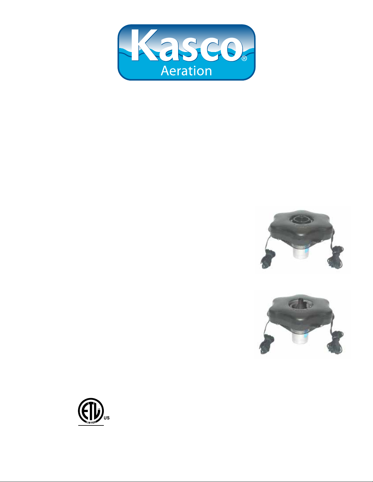
3400JF, 3400HJF Parts Included. . . . pg4
3400JF, 3400HJF Assembly. . . . pg4
4400JF, 4400HJF Parts Included. . . . pg6
4400JF, 4400HJF Assembly. . . . pg7
Nozzle Options. . . . pg9
Installation Instructions. . . . pg10
Control Panel Installation. . . . pg11
C-25 Timer Control Instructions. . . . pg12
C85 non-metallic Wiring Diagram. . . . pg14
C85 / C95 non-metallic and 3 Phase Control Panel Timer. . . . pg15
Maintenance Recommendations. . . . pg16
Warranty Policy. . . . pg17
Troubleshooting Tips. . . . pg18
3400J Replacement Parts. . . . pg20
4400J Replacement Parts. . . . pg21
Customer Repair Form. . . . pg22
Registration Information. . . . pg24
C
Intertek
3020379
ANSI/UL 778, 5th Ed. 2010
CAN/CSA C22.2 No. 108-M89
UL 50, 11th Ed. 1995
Kasco Marine, Inc.
800 Deere Rd.
Prescott, WI 54021
PH (715) 262-4488
FAX (715) 262-4487
www.kascomarine.com
Rev. 07/29/13

THANKS
We at Kasco Marine, Inc. would like to both thank and
congratulate you on your purchase of the JF model
aerating fountain. We appreciate you choosing Kasco
and for your purchase. Your decision to purchase Kasco’s JF model Aerating Fountain will not disappoint
you. The JF model Aerating Fountain will be a great
addition to your body of water. It will help improve
the water quality by adding much needed oxygen and
circulation. It will also enhance the aesthetics of the
pond or lake with a beautiful fountain pattern. The
lighting package (if purchased) will illuminate your
fountain for beauty at night. We thank you for choosing Kasco for your fountain needs and want you to be
completely satised with your purchase.
Important Safety
Please read and follow these extremely important
safety and handling instructions for your Kasco equipment. Following these instructions will help ensure
your safety and the quality performance of your equipment.
PFD. (Personal Flotation Device)
• The fountain is supplied with an internal grounding conductor and a grounding-type attachment
plug. To reduce the risk of electrical shock,
be certain that the fountain is plugged into the
C-25 Control Box (120V) or C-85 Control Panel
(240/208V) supplied by Kasco and that the C-25
is plugged into a properly grounded, grounding
type receptacle or the C-85 is wired properly. The
GFCI breakers should be tested upon each installation and every month thereafter to ensure proper
operation.
General Instructions
INSPECT THE SHIPMENT
Immediately inspect your Kasco Fountain shipment
for any visible damages. Also cross reference the
parts supplied with the Parts Included sheet to check
for shortages. Shortages should be reported immediately to your Kasco Marine distributor or representative and damages reported to your carrier and Kasco
Marine.
• Under NO circumstances should anyone enter the
water with the electrical equipment plugged in
and/or in operation. All Kasco equipment is ETL
approved to UL and CSA standards for safety in
water and all fountain models include control panels with GFI protection. However, it is NEVER
recommended to enter the water with the equipment in operation.
• Caution should be used when dealing with any
electrical equipment with moving parts.
• NEVER run the unit out of water. It will damage
the seals and create a dangerous situation for the
operator.
• Extreme caution should be used around water,
especially cold water, such as in Spring, Fall, and
Winter, which poses a hazard in and of itself.
• NEVER lift or drag the fountain by the power or
light cord. If you need to pull the unit to the side
of the pond, use the anchoring ropes.
• Do not use waders in deep ponds/lakes or ponds/
lakes with drop-offs, drastic slopes, or soft bottom
material.
• Do not use boats that tip easily for fountain installation, such as a canoe, and follow all boating
safety rules and regulations, including wearing a
CAUTION
WARNING: Under NO circumstances should anyone
enter the water with the unit in operation. Always
operate the unit in the water and keep people and objects clear of the propeller. Do not lift or pull the unit
by the electrical cord. Always use extreme caution
around electrical equipment and water situations.
ASSEMBLY & INSTALLATION
Please see the proper Assembly and Installation In-
structions enclosed in this manual. Each is specic for
your model and size of Fountain. Note: Use a nylon
tie to help keep the power cords for the unit and lights
free of the propeller by tying each cord to either side
of the oat. If you have a light kit, make sure that the
unit cord is tied to one side of the oat and the light
cord to the other for balance. Note: It is extremely
important to test the GFI breaker in the control panel
upon each installation/reinstallation of the unit to ensure proper functioning.
WARRANTY
Kasco Fountains are the result of over 40 years of
design and engineering. Kasco products are built to
withstand the toughest conditions. Kasco Marine
2
backs each 3400JF model Fountain with a 2 Year Warranty. This warranty covers any and all manufacturers defects within 2 years from the date of purchase
(See Warranty & Return Policy). Please register your
Fountain online at: www.kascomarine.com (Under the
Technical tab)
tant to store them upside down if they are going to be
sitting for long periods of time. Units that sit upright
on a shelf for many months, or even years have a
greater likelihood of seals drying out. Storing upside
down will ensure oil is lubricating the seals and prevent drying.
USE AND OPERATION
Kasco Fountains are designed and engineered for
continuous duty, such as on sh farms or other aquaculture applications, or on-demand use, as needed in a
recreational water feature.
During otation operation, the water is pulled from
O
360
around the unit and from below the unit. The
water is pulled upward and thrust through the otation
collar into the air.
Your Kasco Marine Fountain is ready for immediate
use (after installation). The motor and ball bearings
are submerged in oil and no further lubrication is
needed. Make sure to keep the motor housing clean
from hard water deposits and/or algae. (See Maintenance Recommendations.)
It is extremely important that proper and sufcient
voltage (120V or 240/208V) is supplied to the Fountain motor. Each 120V Fountain is supplied with a
UL and CSA approved C-25 GFI Protected Control
Box. The Fountain is to be plugged into the C-25
outlet labeled “UNIT” and the C-25 plugged into a
properly grounded receptacle (See C-25 Instructions
on page 12). Each 240V Fountain is supplied with a
UL and CSA approved C-85 GFCB Protected Control
Panel. The Fountain is to be plugged into the external
outlet on the C-85 or hardwired into C-85 panel. The
C-85 must have 4 wire service (L1, L2, neutral, and
ground) installed by a qualied electrician. (See Wiring Instructions). It is extremely important to test the
GFI breaker in the control panel upon each installation
and reinstallation and every month thereafter to ensure
proper operation.
Cord Gauge Chart
Length Gauge 3400 3400H
4400H
50’ 16 x
50’ 14 x x
100’ 14 x x
100’ 12 x
150’ 12 x x
150’ 10 x
200’ 12 x x
200’ 10 x
250’ 12 x
300’ 12 x
400’ 12 x
4400
Unit Specs
Model Voltage Amps Lock
rotor
amps
3400JF 110-120 7.3 18 C-25
3400HJF 208-240 3.7 9 Hardwire
4400JF 110-120 11 40 C-25
4400HJF 208-240 5.5 20 Hardwire
Control
box con-
nection
plug in
C-85
plug in
C-85
Fountain
connec-
tion
Plug into
C-25
plug into
or hard-
wire C85
Plug into
C-25
plug into
or hard-
wire C85
Kasco Fountains are lightweight, energy efcient, and
easy to install and operate. We strive to produce products that exceed customer expectations. We hope you
enjoy your Kasco Fountain.
UNIT STORAGE
When storing units during the offseason, it is impor-
3

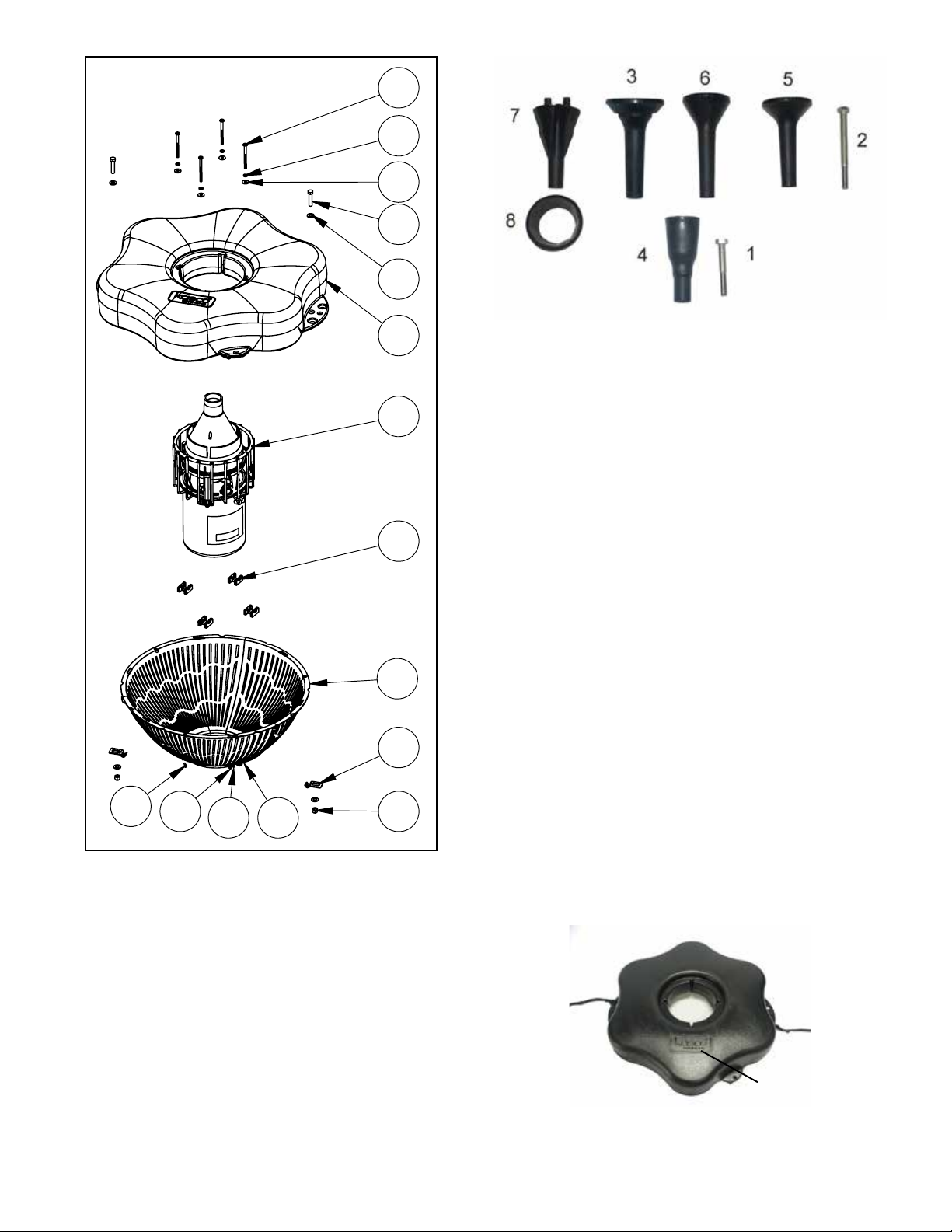
3400JF, 3400HJF Parts Included
REV.
ECO#
DESCRIPTION
1
INITIAL RELEASE
DO NOT SCALE DRAWING
X
UNLESS OTHERWISE SPECIFIED
DIMENSIONS ARE IN INCHES.
MATERIAL:
1. 3400JF Aerating Fountain (Unit with cord or unit
with Disconnect) (1)
2. Float (with two 50’ mooring ropes attached) (1)
3. 1/4-20 x 3 1/2” Phillips Pan Head Screw (4)
4. 1/4” split washers (4)
5. 1/4” (3/4” outer diameter) Flat Washer (4)
6. 3/8”-16 x 1-3/4” Hex Head Bolt (2)
7. 3/8” Flat Washer (4)
8. Cushions for Legs (4)
9. Bottom Screen section (3)
10. Bottom Screen Clips (2)
11. 3/8”-16 Nylon Lock Nut (2)
12. #8 nut (6)
13. #8 at washer (12)
14. #8 lock washer (6)
15. #8 x 1/2” Screw (6)
Set of 5 Interchangeable Nozzles (5)
1. 3/8” x 2.25” bolt (1)
2. 3/8” x 4” bolt (1)
3. Linden Nozzle (1)
4. Sequoia Nozzle (1)
5. Juniper Nozzle (1)
6. Willow Nozzle (1)
7. Cypress Nozzle (1)
8. Collar for Cypress Nozzle (1)
3
4
Also Included:
• Mooring Rope Tube Weights (2)
5
• Cord in separate box (1) (depending on size of
cord)
6
• Control Box (C-25 for 120V units in Float box
or C-85 for 240V units in separate box) (1) (Not
7
2
Pictured)
TOOLS & SUPPLIES NEEDED
• Anchors or stakes for installing unit (2)
• # 2 Phillips head screw driver
• 120V or 240V Electrical Supply near pond on a
8
post with room for mounting the C-25 or C-85
• #10 x 1” long or longer screw(s) for mounting the
1
C-25 (3) or C-85 (4)
• 9/16” Socket and Ratchet
• 9/16” Wrench
• 11/32” wrench (for #8 fasteners)
9
1. Make sure you have all the parts needed. If any short-
ages are found, contact your Kasco representative immediately.
10
2. Set motor housing upright (stainless steel can down) on
a at surface.
12
4
1113 14 15
3. Peel off the adhesive on one of the Cushions for the
fountain housing legs (Part 8). Stick to the top of the fountain housing leg and repeat for the other three cushions.
3400JF, 3400HJF Assembly
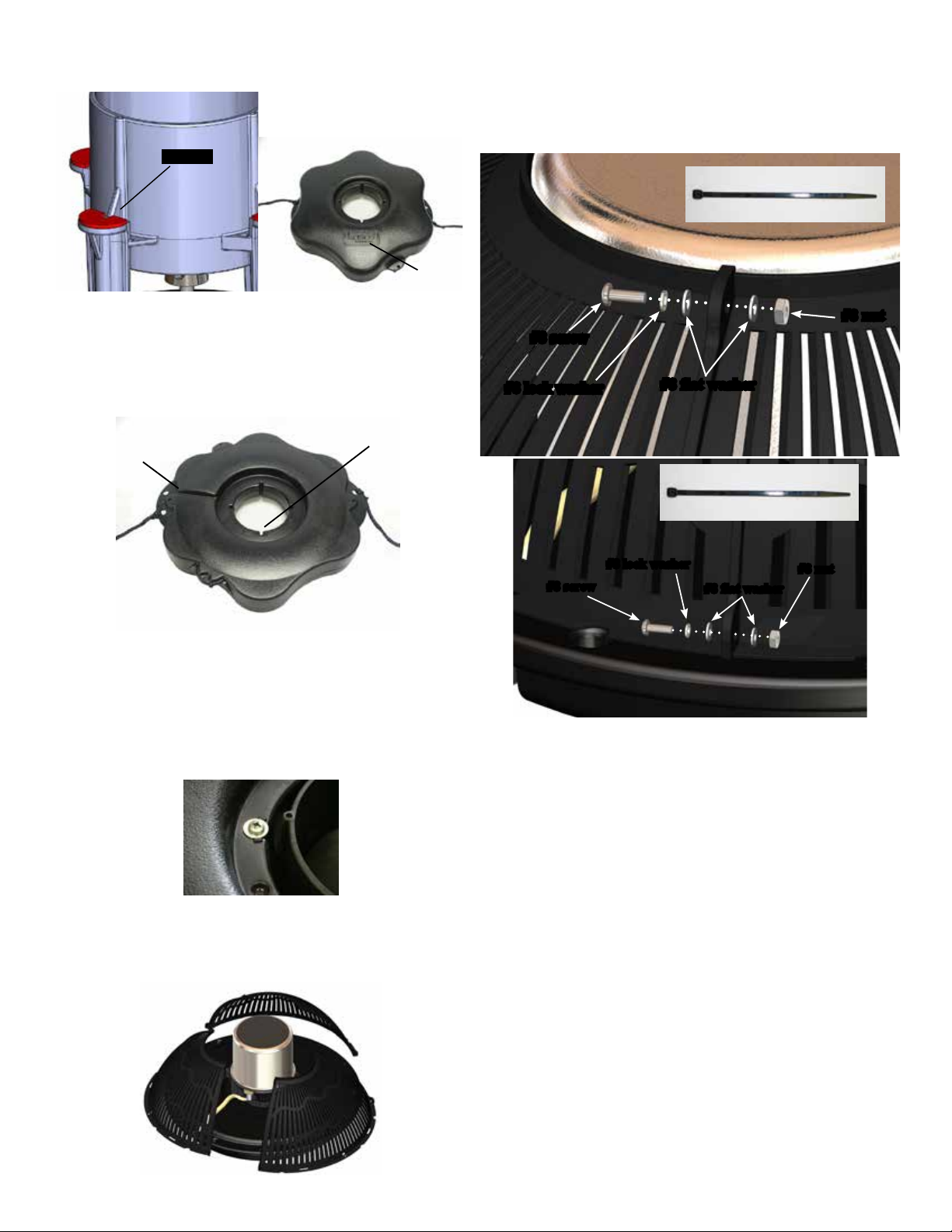
Rest the oat on the 4 legs of the housing making sure logo
on oat is up.
cushion
logo
7. Secure the 3 sections of the screen together in 6 places
using #8 screw (Part 15), #8 lock washer (part 14), two
#8 at washers (part 13), and #8 nut (part 12). Do not
overtighten. Alternately, use cable ties instead of hardware
for a quicker assembly of the screen.
For quicker assembly:
Use cable tie instead
4. Ensure correct alignment by twisting the oat gently
around the motor housing until the power cord guide lines
up with the cord. See diagram below of bottom side of
oat. The 4 bolt holes in the oat should line up with bolt
receptacles on unit.
power cord
Bolt holes
guide
5. Use one of the 1/4”-20 x 3-1/2” Phillips Pan Head
Screws (Part 3), one 1/4” split washer (Part 4), and a 1/4”
Flat Washer (Part 5) to secure the oat. Make sure the split
washer goes between the bolt head and the at washer.
Insert screw with washers through bolt hole in oat
Tighten until snug with a Phillips Head screw driver and
repeat for 3 remaining screws.
6. Turn secured assembly upside down so the top of the
oat (logo side) is face down on the at surface. Bring the
3 bottom screen sections (part 9) together.
#8 nut
#8 screw
#8 lock washer
#8 lock washer
#8 screw
#8 flat washer
For quicker assembly:
Use cable tie instead
#8 nut
#8 flat washer
8. Make sure the cord is coming out of the power cord
guide in the oat before attaching the screen to the oat.
9. Use a stainless steel Bottom Screen Clip, 3/8”-16 x
1-3/8” Bolt, two 3/8” Flat Washer, and 3/8”-16 Nylon Lock
Nut to secure the screen to the oat. Align a clip so the two
prongs overlap the rim of the screen as seen in the picture.
Insert bolt with washer so the top of the bolt is facing the
top of oat (now in down position). Place the second
washer and the locking nut with nylon insert on the end of
the bolt and tighten using the 9/16” (14mm) Socket and
Ratchet on the nut end and the 9/16” (14mm) Wrench on
the bolt end. Tighten until snug and repeat with remaining
clip.
5
3/8” lock nut
3/8” flat washer
Bottom screen clip
3/8” flat washer
3/8” bolt
10. Turn the assembly upright again. At this time, if the
cord contains a metal strain relief, you can use the chain
connector and attach it in one of the opening at the rope
placement. The chain connector will easily t if installed
from the bottom or top side of the opening. It will not t
if installed from side of opening. Use the Nylon Cable Tie
included to secure the power cord to a molded hole in the
oat to prevent cord damage if there is no strain relief on
the cord. If a Strain Relief is present on the cord, you may
disregard the Nylon Tie. On cords with a Quick Disconnect, the disconnect should be tightened properly to avoid
leaking. If installing a new Quick Disconnect, refer to
Quick Disconnect Instructions.
12. Thread one rope through one weighted tube rope
Weight and position it approximately 6’ from the oat.
Next, thread the end of the rope back through the opening
facing the oat (as shown). Repeat with the second rope
and weight. If ready to install in the pond, go to Installation instructions. Light Kits can also be installed at this
time, go to Light kit instructions.
4400JF, 4400HJF Parts Included
1. 4400JF Aerating Fountain (Unit with cord or unit with
Disconnect) (1)
2. Float (with two 50’ mooring ropes attached) (1)
3. 1/4-20 x 3 1/2” Phillips Pan Head Screw (4)
4. 1/4” split washers (4)
5. 1/4” (3/4” outer diameter) Flat Washer (4)
6. 3/8”-16 x 1-3/4” Hex Head Bolt (2)
7. 3/8” Flat Washer (4)
8. Float Retaining Clips (4)
9. Bottom Screen section (3)
10. Bottom Screen Clips (2)
11. 3/8”-16 Nylon Lock Nut (2)
12. #8 nut (6)
13. #8 at washer (12)
14. #8 lock washer (6)
15. #8 x 1/2” Screw (6)
11. Select a nozzle (See JF Nozzle Options). Insert the
Shaft Bolt into the Nozzle Head so it ts snugly into the
molded socket. Install the Nozzle by threading it into the
inner cone of the pump. Make sure to tighten the Nozzle
all the way down.
6
3
REV.
ECO#
1
INITIAL RELEASE
DO NOT SCALE DRAWING
C.A.D. GENERATED DRAWING
X
UNLESS OTHERWISE SPECIFIED
DIMENSIONS ARE IN INCHES.
DIMENSIONS IN [ ] ARE MILLIMETERS.
MATERIAL:
4
5
6
7
12
14 15
2
1
8
9
10
1113
Also Included:
• Cord in separate box (1) (depending on size of cord)
• Control Box (C-25 for 120V units in Float box or C-85
for 240V units in separate box) (1) (Not Pictured)
TOOLS & SUPPLIES NEEDED
• Anchors or stakes for installing unit (2)
• # 2 Phillips head screw driver
• 120V or 240V Electrical Supply near pond on a
post with room for mounting the C-25 or C-85
• Two 12” pieces of 1” galvanized pipe or weighted
tubing for weighting ropes (optional)
• #10 x 1” long or longer screw(s) for mounting the
C-25 (3) or C-85 (4)
• 9/16” Socket and Ratchet
• 9/16” Wrench
• 11/32” wrench (for #8 fasteners)
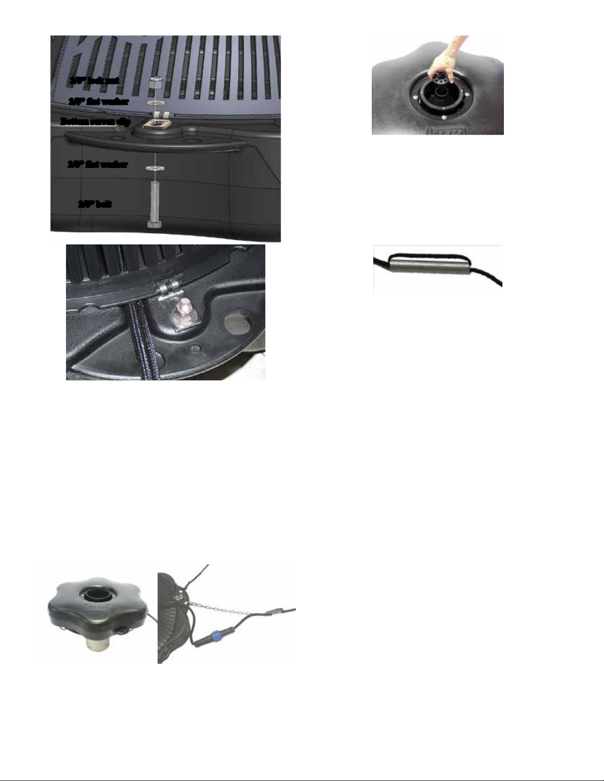
4400JF, 4400HJF Assembly
1. Make sure you have all the parts needed. If any short-
ages are found, contact your Kasco representative immediately.
Set of 5 Interchangeable Nozzles (5)
1. 3/8” x 2.25” bolt (1)
2. 3/8” x 4” bolt (1)
3. Linden Nozzle (1)
4. Sequoia Nozzle (1)
5. Juniper Nozzle (1)
6. Willow Nozzle (1)
7. Cypress Nozzle (1)
8. Collar for Cypress Nozzle (1)
2. Set motor housing upright (stainless steel can down) on
a at surface. With motor housing upright, slide Float (Part
2) over pump housing making sure the surface with the
Kasco logo is up.
logo
Rest the oat on the cage top ring.
7

3. Ensure correct alignment by twisting the oat gently
around the motor housing until the power cord guide lines
up with the cord. See diagram of bottom side of oat.
power cord
Bolt holes
guide
4. Use one of the 1/4”-20 x 3-1/2” Phillips Pan Head
Screws (Part 3), one 1/4” split washer (Part 4), and a 1/4”
Flat Washer (Part 5) to secure the oat. Make sure the split
washer goes between the bolt head and the at washer.
Insert screw with washer through bolt hole in oat
Use one oat retaining clip (Part 8) under the top ring of
the cage. There is a U-shaped indent in the clip that will t
snug against the top ring of the cage. The 1/4”-20 x 3-1/2”
will then thread into the retaining clip.
oat retain
ing clip
7. Secure the 3 sections of the screen together in 6 places
using #8 screw (Part 15), #8 lock washer (part 14), two
#8 at washers (part 13), and #8 nut (part 12). Do not
overtighten.
#8 nut
#8 screw
#8 lock washer
#8 flat washer
5. Tighten until snug with a Phillips Head screw driver and
repeat for 3 remaining screws.
6. Turn secured assembly upside down so the top of the
oat (logo side) is face down on the at surface. Bring the
3 bottom screen sections (part 9) together.
8
#8 screw
#8 lock washer
#8 flat washer
#8 nut
8. Make sure the cord is coming out of the power cord
guide in the oat before attaching the screen to the oat.
9. Use a stainless steel Bottom Screen Clip, 3/8”-16 x
1-3/8” Bolt, two 3/8” Flat Washer, and 3/8”-16 Nylon Lock
Nut to secure the screen to the oat. Align a clip so the two
prongs overlap the rim of the screen as seen in the picture.
Insert bolt with washer so the top of the bolt is facing the
top of oat (now in down position). Place the second
washer and the locking nut with nylon insert on the end of
the bolt and tighten using the 9/16” (14mm) Socket and
Ratchet on the nut end and the 9/16” (14mm) Wrench on
the bolt end. Tighten until snug and repeat with remaining
 Loading...