

Kasco 4400EJ User Manual [en, de, es, fr, it]

Owners Manual
50Hz Fountains
2400EVX, 3400EVX, 4400EVX
2400EJ, 3400EJ, 4400EJ
Contents
Important Safety Instructions . . . . . .pg2
Unit Specs . . . . . .pg2
Quick Disconnect Installation . . . . . .pg2
Wire Sizing & Gland Sizing . . . . . .pg4
2400EVX, 2400EJ, 3400EVX, 4400EVX Parts . . . . . .pg4
EVFX Pattern Size Chart . . . . . .pg5
2400EVX, 2400EJ, 3400EVX, 4400EVX Assembly Instructions . . . . . .pg5
3400EJ, 4400EJ Parts . . . . . .pg6
3400EJ, 4400EJ Assembly . . . . . .pg7
2400EJ, 3400EJ, 4400EJ Nozzle Options . . . . . .pg8
Installation Instructions . . . . . .pg10
Maintenance Recommendations . . . . . .pg11
Troubleshooting Tips . . . . . .pg11
Kasco Marine, Inc.
800 Deere Rd.
Prescott, WI 54021
U.S.A.
PH 00+1+715+262+4488
FAX 00+1+715+262+4487
sales@kascomarine.com
www.kascomarine.com
Rev. 12/15/09
CAUTION
Unit Specs
NOTICE (NOTE)
These international safety symbols are used
throughout this manual to inform the owner of
important safety information and notices for
safe and effective use of the equipment.
Important Safety Instructions
CAUTION
Under NO circumstances should anyone enter •
the water with the electrical equipment connected and/or in operation. It is NEVER recommended to enter the water with the equipment in operation.
Caution should be used when dealing with any •
electrical equipment with moving parts.
NEVER run the unit out of water. It will dam-•
age the seals and create a dangerous situation
for the operator.
Extreme caution should be used around water, •
especially cold water, such as in Spring, Fall,
and Winter, which poses a hazard in and of
itself.
NEVER lift or drag the unit by the power or •
light cord. If you need to pull the unit to the
side of the pond, use the anchoring ropes.
Do not use waders in deep ponds/lakes or •
ponds/lakes with drop-offs, drastic slopes, or
soft bottom material.
Do not use boats that tip easily for fountain •
installation, such as a canoe, and follow all
boating safety rules and regulations, including
wearing a PFD. (Personal Flotation Device)
The unit is supplied with an internal ground-•
ing conductor. To reduce the risk of electrical
shock, be certain that the unit is plugged/connected to an approved RCD (GFCI) protected
circuit.
Means for disconnection must be incorporated •
in the fi xed wiring in accordance with local and
national wiring rules.
Consult a qualifi ed electrician for electrical •
installation.
Model Voltage
range
2400EVX 208-240 2.2@220V 6@220V
3400EVX 208-240 3.6@220V 9@220V
4400EVX 208-240 5.9@220V 20@220V
2400EJ 208-240 2.2@220V 6@220V
3400EJ 208-240 3.8@220V 9@220V
4400EJ 208-240 6.5@220V 20@220V
Operating
amps
lock rotor
amps
Quick Disconnect Installation
Important – Read Carefully Before Installation
Before using the connector, it is important that these
instructions are carefully read and understood to
ensure the connector system is completely water tight
and electrically safe.
IF IN DOUBT CONSULT A QUALIFIED ELECTRICIAN.
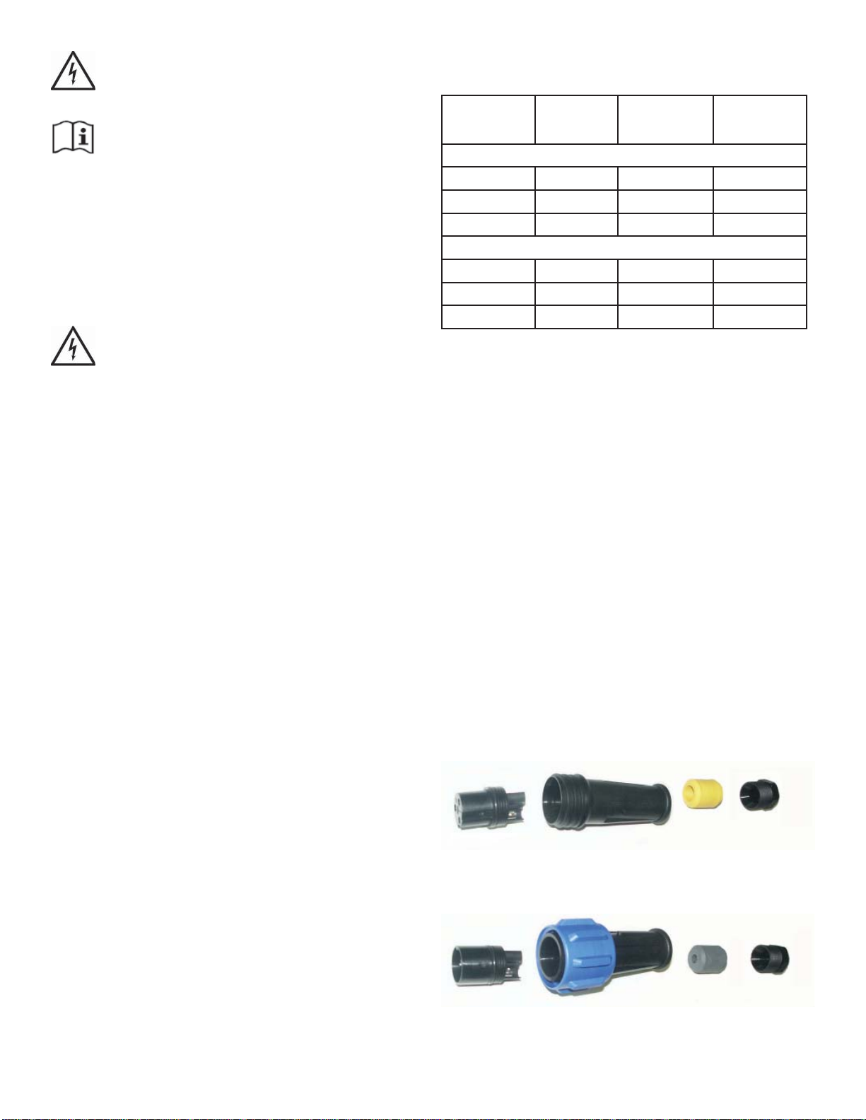
The socket (female) insert of the connector must be
the live part of the connector from the supply. The pin
(male) insert of the connector must lead to the load or
electrical device. On 50Hz units, the pin (male) insert
of the connector is installed at the factory. To ensure
effi cient sealing, use only smooth circular cable.
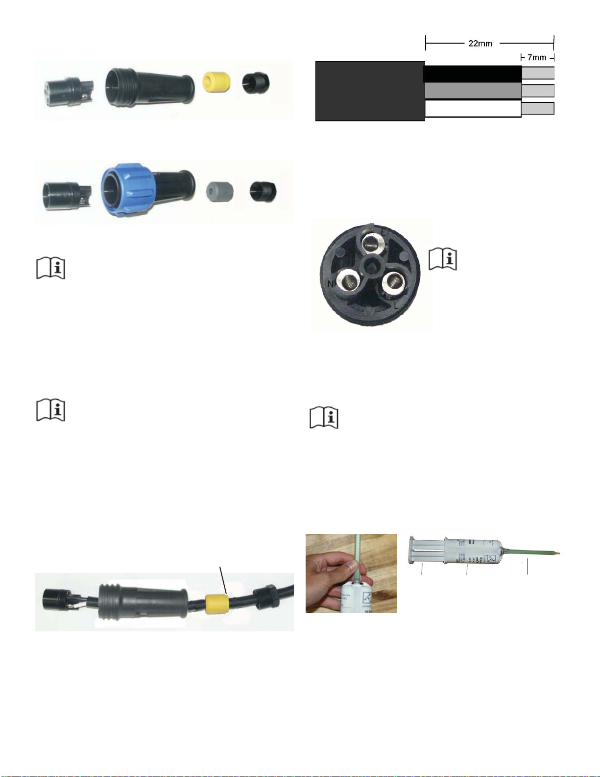
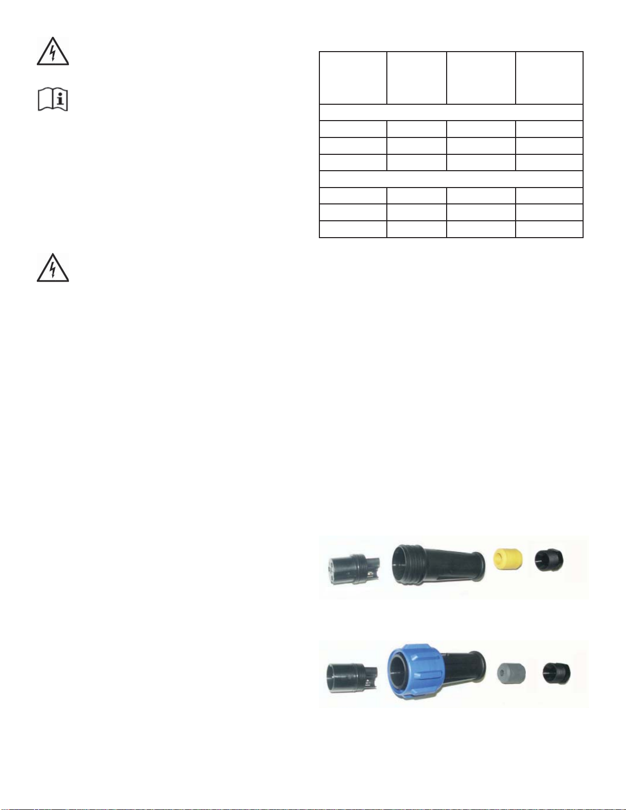
Pin Insert (Installed on Stub Cord)
Pin Insert
Gland
Main Body
Gland Nut
Socket Insert (User Installed)
Socket insert
Gland
Main Body
Gland Nut
2
Note:
White gland for 9-11mm O.D.
Yellow gland for 13-15mm O.D.
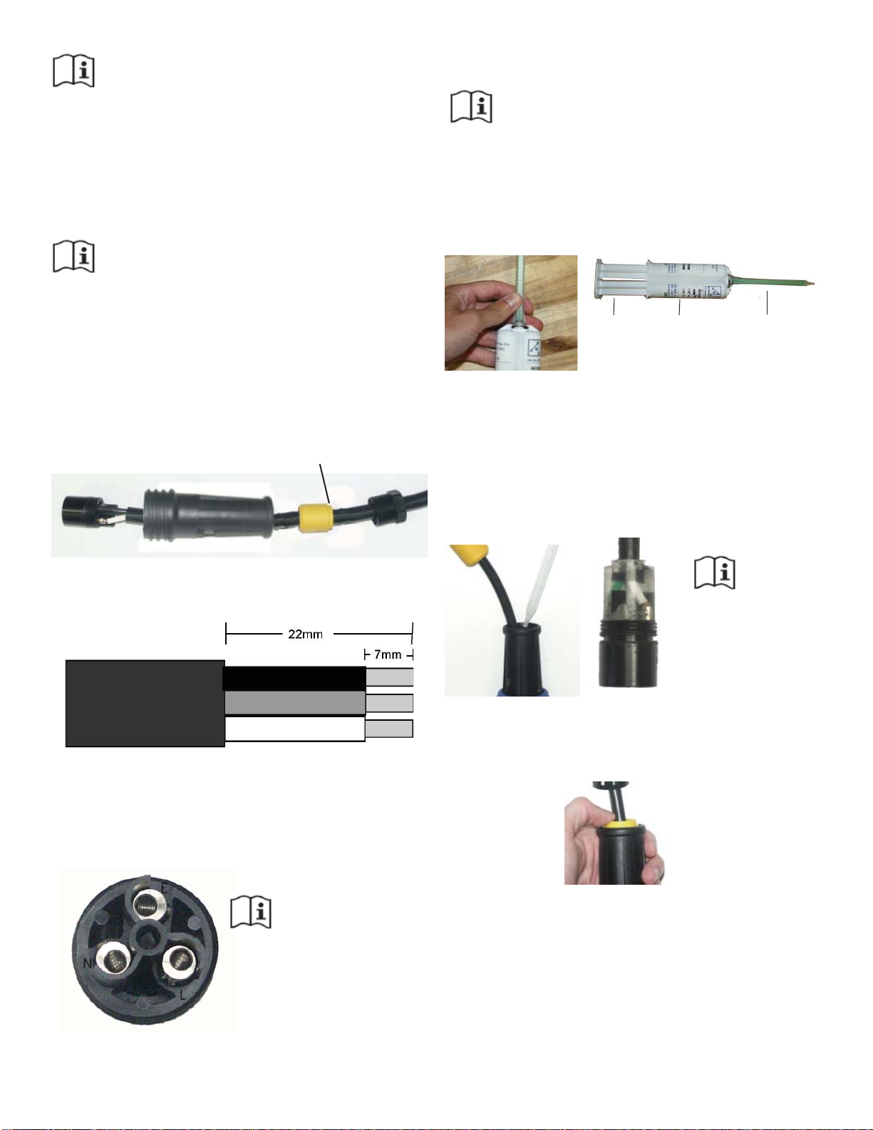
Assembly/Wiring Instructions
STEP ONE
Remove the socket insert from the housing of
the connector. There is a slot for a fl at blade
screwdriver in the center of the insert.
Note: The inserts have a LEFT HAND
THREAD and should be turned clockwise to remove.
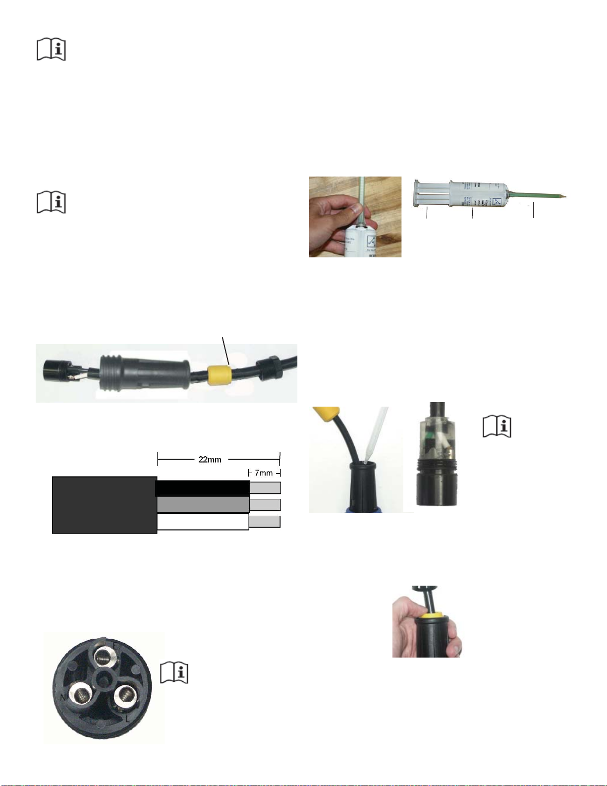
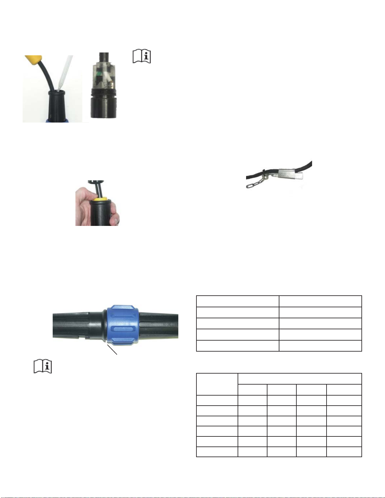
STEP TWO
Remove the gland nut and gland from the rear of the
housing and slide on to the cable. Make sure the gland
is orientated with the stepped edge facing the gland
nut (see picture).
Stepped Edge
After the wires have been connected securely, pull the
cable and insert back into the housing and tighten with
a screwdriver to ensure the insert is seated correctly.
Note: LEFT HAND THREAD, turn the insert counter
clockwise to tighten.
STEP FIVE
Prepare your supplied Resin Kit by removing the cap
from the resin tube and pushing the resin nozzle onto
the tube. Then twist the nozzle to lock in place.
Plunger Resin Tube Nozzle
Before applying to the quick disconnect, use the
plunger to evenly push out a small amount of resin to
get a proper mix of of the 2-part epoxy. Then apply
resin into the housing, enough to cover the wires and
contacts. The resin should be about 3mm onto the
cord jacket. Note: Adding too much resin may cause
excess to be forced into the female end of the pin
connector, preventing proper connection of the two
halves.
STEP THREE
Prepare the cable and strip wire ends as shown.
Wire Stripping
STEP FOUR
Insert the stripped wire ends into the terminals on the
back of the Pin/Socket insert and fully tighten the
wire retention screws. (Refer to fi gure for correct wire
orientation).
Figure 5:
Wire Connections
Brown wire to terminal L
Blue wire to terminal N
Green/Yellow wire to terminal E
Cut-Away
disconnect shown
with clear resin.
Note amount that is
covering cord jacket.
STEP SIX
Slide the gland and gland nut along the cable into the
body and tighten the gland nut securely. No drying
time is needed for the epoxy before full assembly.
3

STEP SEVEN
Once the two subassemblies have been completed,
they can be joined together. Plug pin assembly into
the socket assembly and tighten the large blue nut
securely. The blue nut should be hand tightened only.
(See fi gure below).
Note: There is a small gap after tightening
For seasonal removal, your quick disconnect includes
an optional water tight cover. Simply separate the
quick disconnect and insert the sealing cover into the
large blue nut half and tighten fi rmly.
Strain Relief
The Strain Relief must be installed to protect the
Quick Disconnect from damage due to excessive
strain. The Strain Relief should be installed on the
user supplied cord length (not on the Kasco supplied
stub cord). It should be position about 15cm from the
Quick Disconnect. To install, insert the narrow end of
the elongated clamp with the chain connected into the
wide end of the short clamp. Use a rubber mallet to
tap the two pieces together securely. A Nylon Tie can
be used to keep it attached to the cord. The chain can
then be attached to the fl oat.
Gland O.D. of Cord
White 9-11mm
Black 11-13mm
Yellow 13-15mm
Kasco 50 Hz Equipment Wire Size Chart
Model Cord Length
10m 30m 60m 90m
4mm
4mm
2
2
2
2
2
2
2400EVX 1.5mm21.5mm22.5mm22.5mm
2400EJ 1.5mm21.5mm22.5mm22.5mm
3400EVX 1.5mm21.5mm22.5mm22.5mm
3400EJ 1.5mm21.5mm22.5mm22.5mm
4400EVX 1.5mm21.5mm22.5mm
4400EJ 1.5mm21.5mm22.5mm
2
2
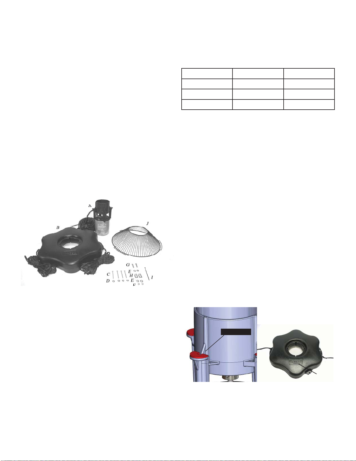
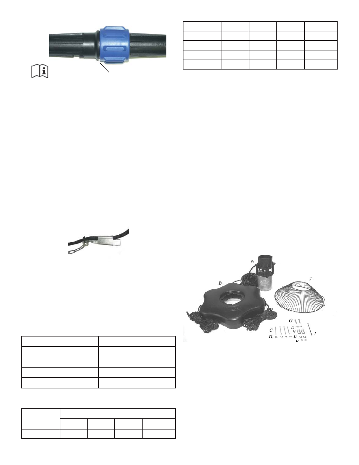
2400EVX, 2400EJ, 3400EVX,
4400EVX Parts
A. EV or EJ Aerating Fountain (Unit with cord or
stub cord) (1)
B. Float(with two 50’ mooring ropes attached) 1
C. 1/4-20 x 3 1/4” Phillips Pan Head Screw (4)
D. 1/4” (3/4” outer diameter) Flat Washer (4)
E. 3/8” Flat Washer (4)
F. 3/8”-16 Nylon Lock Nut (2)
G. 3/8”-16 x 1-3/8” Hex Head Bolt (2)
H. Bottom Screen Clips (2)
I. Nylon Cable Tie
J. Bottom Screen
K. Interchangeable nozzles for 2400EJF only
(See 2400EJF Nozzle Options section)
Wire Sizing & Gland Sizing
The chart below shows the proper Gland to be used
with different cord sizes. The measurements are based
on the Outside Diameter (O.D.) of the cord. Smooth,
round cords should be used.
Kasco Quick Disconnect 50 Hz Size Chart:
Gland O.D. of Cord
Grey 7-9mm
4
Also included: (not pictured)
L. Cushions for fountain housing legs (4)
M. Cushions for bottom screen (3)
N. 1/4” split washers (4)
TOOLS & SUPPLIES NEEDED
A. Anchors or stakes for installing unit (2)
B. # 2 Phillips head screw driver
C. 208-240V Electrical Supply near pond on a post
D. Two 30cm pieces of 2.54cm galvanized pipe for
weighting ropes (optional)
E. 9/16” (14mm) Socket and Ratchet
F. 9/16” (14mm) Wrench
EVFX Pattern Size Chart
All produce a V-shaped display.
Model Height Width
2400EVX 1.15 m 4.3 m
cushion
logo
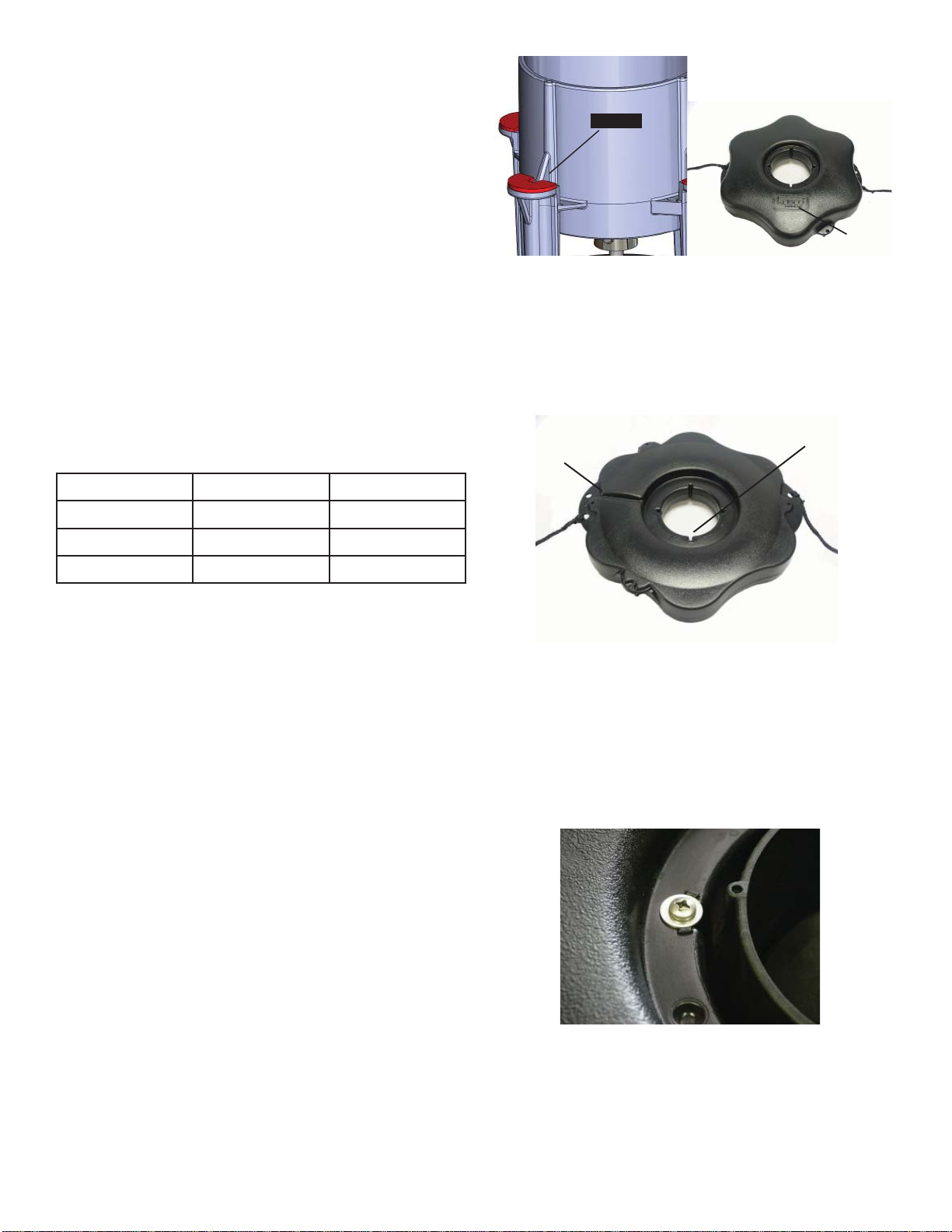
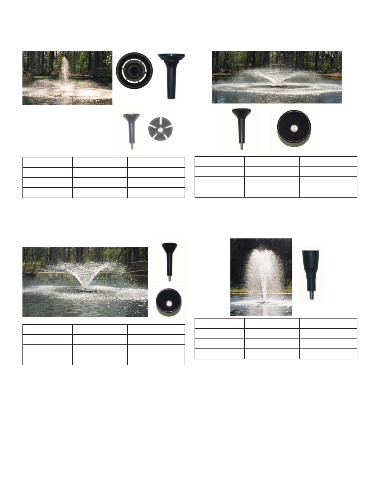
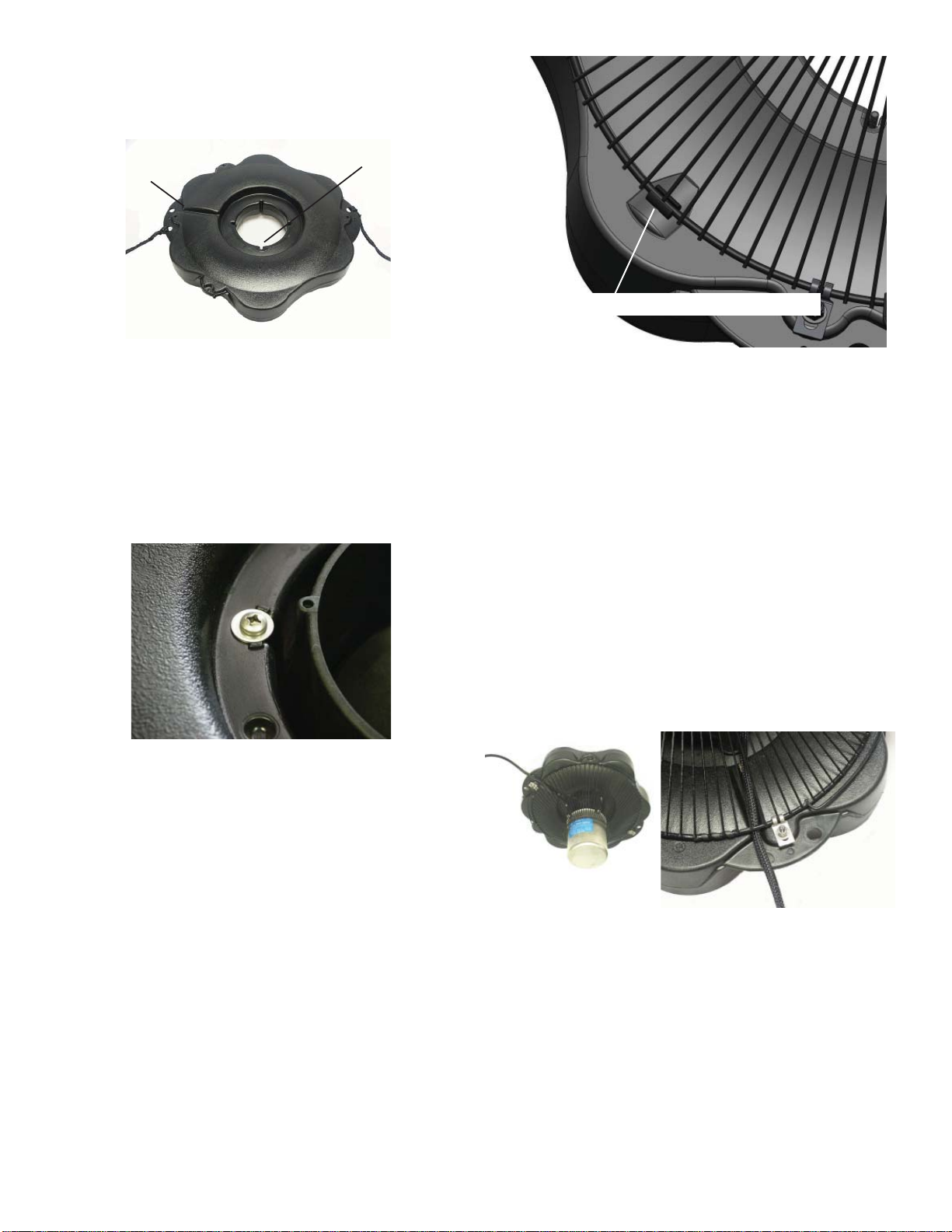
STEP THREE
Ensure correct alignment by twisting the fl oat gently
around the motor housing until the fl oat “locks” into
place, the bolt holes in fl oat line up with bolt recep-
tacles on unit and power cord guide lining up with the
cord. See diagram below of bottom side of fl oat.
power cord
guide
Bolt holes
3400EVX 1.7 m 6.1 m
4400EVX 1.7 m 6.7 m
2400EVX, 2400EJ, 3400EVX,
4400EVX Assembly Instructions
STEP ONE
Make sure you have all the parts needed. If any shortages are found, contact your Kasco representative
immediately.
STEP TWO
Set motor housing upright (stainless steel can down)
on a fl at surface.
Peel off the adhesive on one of the cushions (Part L)
for the fountain housing legs. Stick to the top of the
fountain housing leg and repeat for the other three
cushions and legs. Slide fl oat (Part B) over pump
housing and rest the fl oat on the 4 legs of the housing
making sure the Kasco logo is up.
STEP FOUR
Use one of the 1/4”-20 x 3-1/4” Phillips Pan Head
Screws (Part C), one 1/4” split washer (Part N), and
a 1/4” Flat Washer (Part D) to secure the fl oat. Make
sure the split washer goes between the bolt head and
the fl at washer. Insert screw with washers through
bolt hole in fl oat
STEP FIVE
Turn secured assembly upside down so the top of the
fl oat (logo side) is face down on the fl at surface. Place
Bottom Screen (Part J) onto the bottom side of the
fl oat. Make sure the wide opening of the screen is
5
against the fl oat and the 3 handles on the screen do not
interfere with the rope placements.
Screen cushions (Part M) underneath the screen and
on top of the 3 spacing bumps on the bottom of the
fl oat.
Bottom Screen cushion
Fit the 3 Bottom
Using a stainless steel Bottom Screen Clip (Part
H), 3/8”-16 x 1-3/8” Bolt (Part G), two 3/8” Flat
Washer (Part E), and 3/8”-16 Nylon Lock Nut
(Part F) to secure the screen to the fl oat. Align a
clip so the two prongs straddle a wire on the
screen. Insert bolt with washer so the top of the
bolt is facing the top of fl oat (now in down posi-
tion). Place the second washer and the locking nut
with nylon insert on the end of the bolt and tighten
using the 9/16” (14mm) Socket and Ratchet on the
nut end and the 9/16” (14mm) Wrench on the bolt
end. Tighten until snug and repeat with remaining
clip.
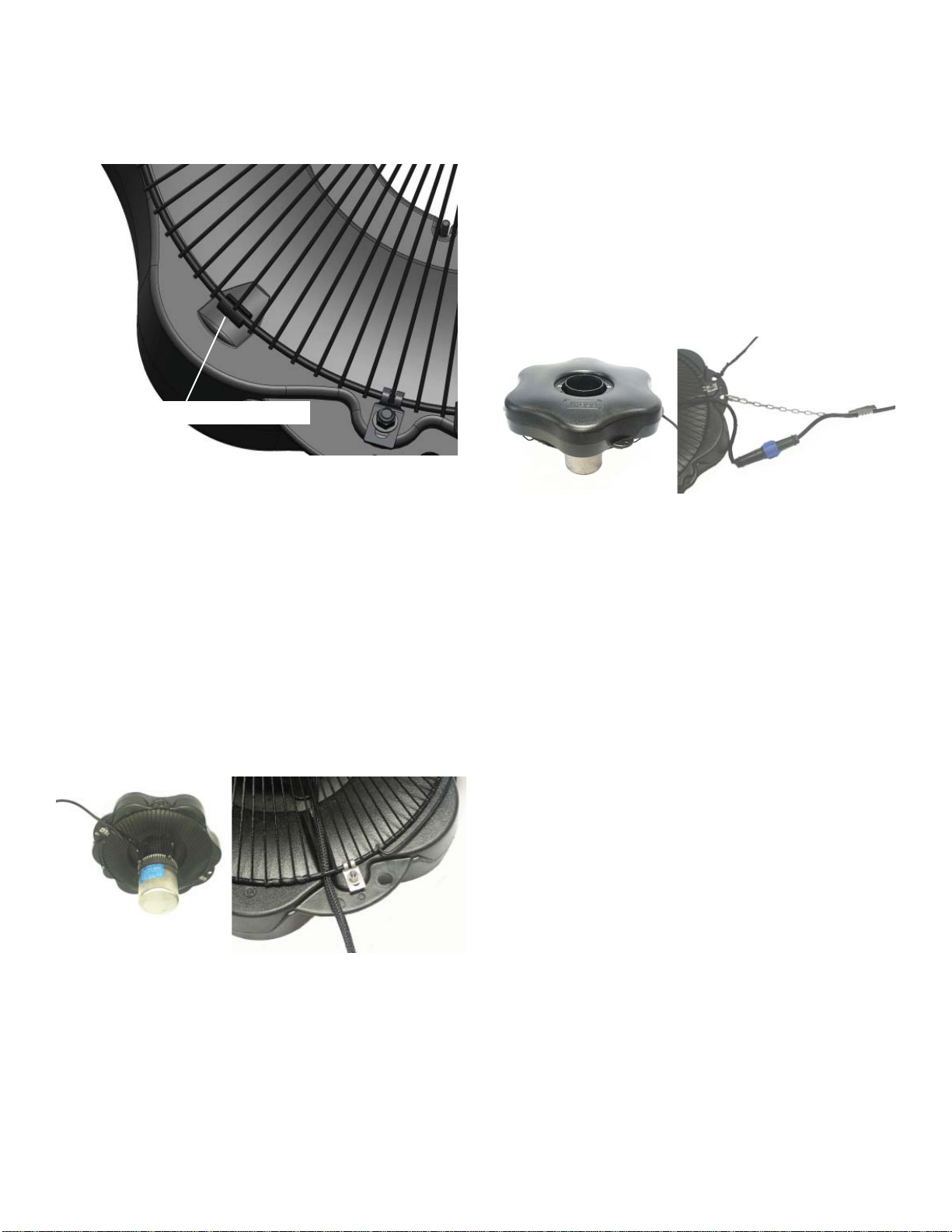
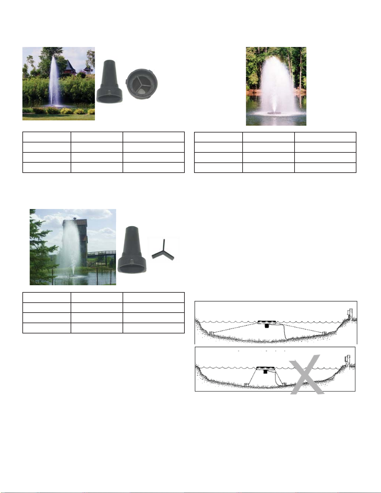
not fi t if installed from side of opening. Use
the Nylon Cable Tie (Part I) included to secure
the power cord to a molded hole in the fl oat to
prevent cord damage if there is no strain relief
on the cord. If a Strain Relief is present on the
cord, you may disregard the Nylon Tie. On
cords with a Quick Disconnect, the disconnect
should be tightened properly to avoid leaking.
If installing a new Quick Disconnect, refer to
Quick Disconnect Instructions. If ready to install in the pond, go to Installation instructions.
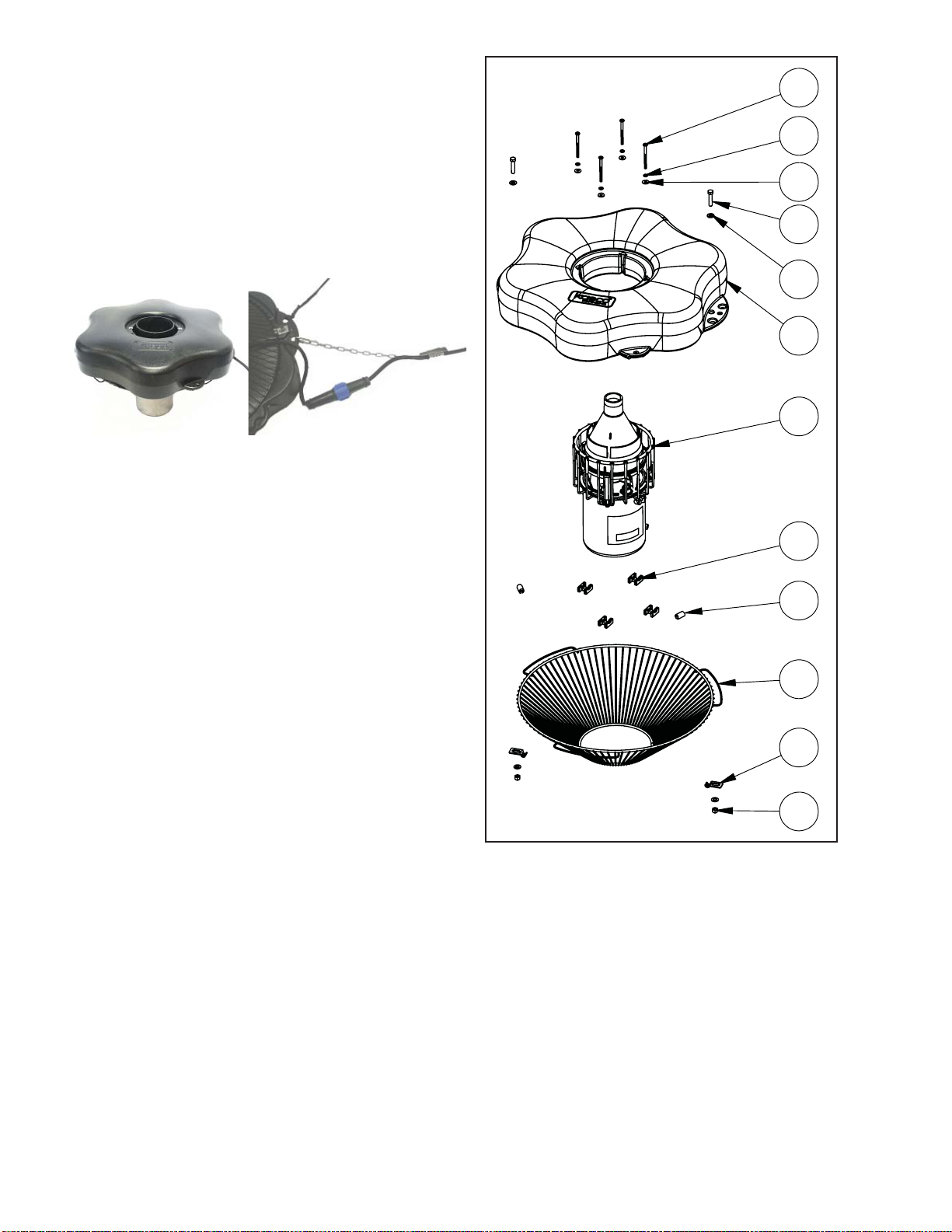
3400EJ, 4400EJ Parts
Aerating Fountain (Unit with cord or unit with 1.
Disconnect) (1)
Float (with two 50’ mooring ropes attached) (1)2.
1/4-20 x 3 1/4” Phillips Pan Head Screw (4)3.
1/4” split washers (4)4.
1/4” (3/4” outer diameter) Flat Washer (4)5.
3/8”-16 x 1-3/8” Hex Head Bolt (2)6.
3/8” Flat Washer (4)7.
Float Retaining Clips (4)8.
Bottom Screen cushions (3)9.
Bottom Screen (1)10.
Bottom Screen Clips (2)11.
3/8”-16 Nylon Lock Nut (2)12.
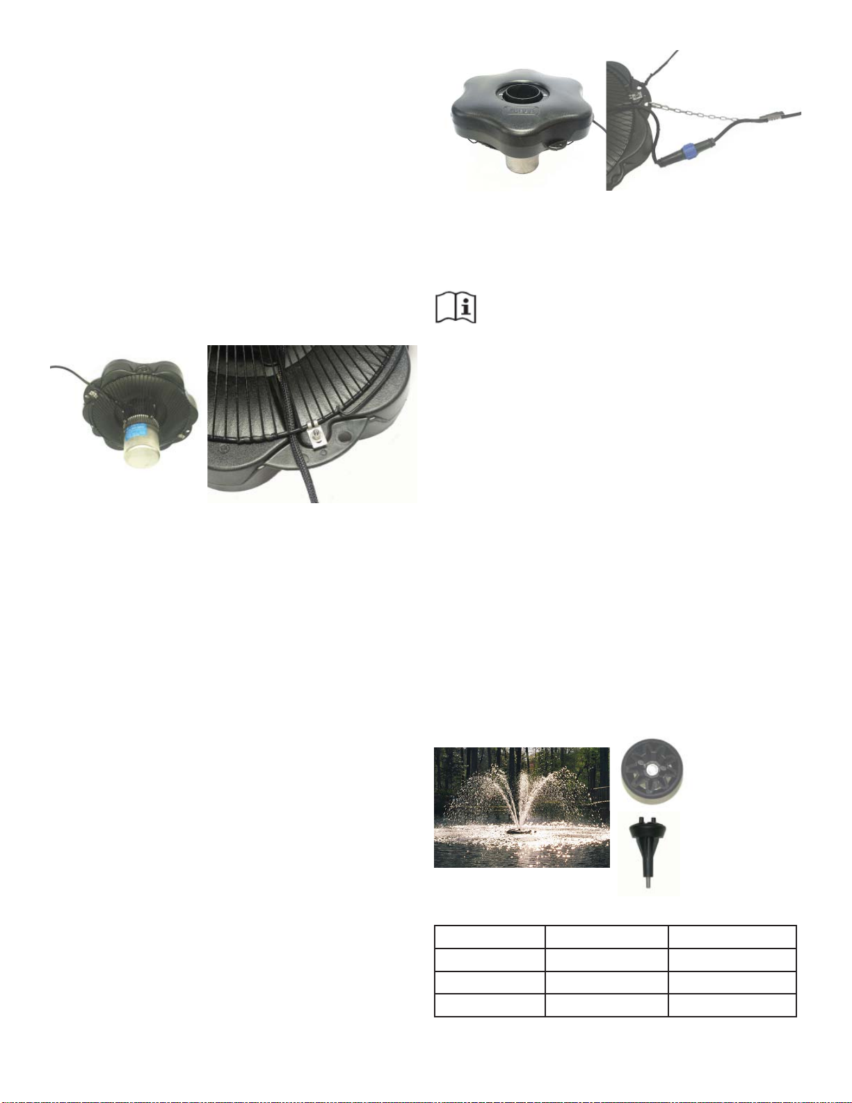
STEP SIX
Turn the assembly upright again. At this time,
if the cord contains a metal strain relief, you
can use the chain connector and attach it in
one of the opening at the rope placement. The
chain connector will easily fi t if installed from
the bottom or top side of the opening. It will
6
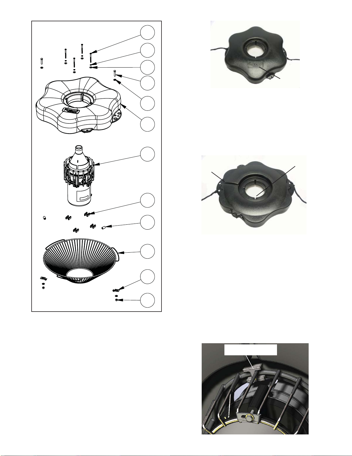
fl oat retain
ing clip
3
4
5
logo
6
7
2
1
8
9
10
11
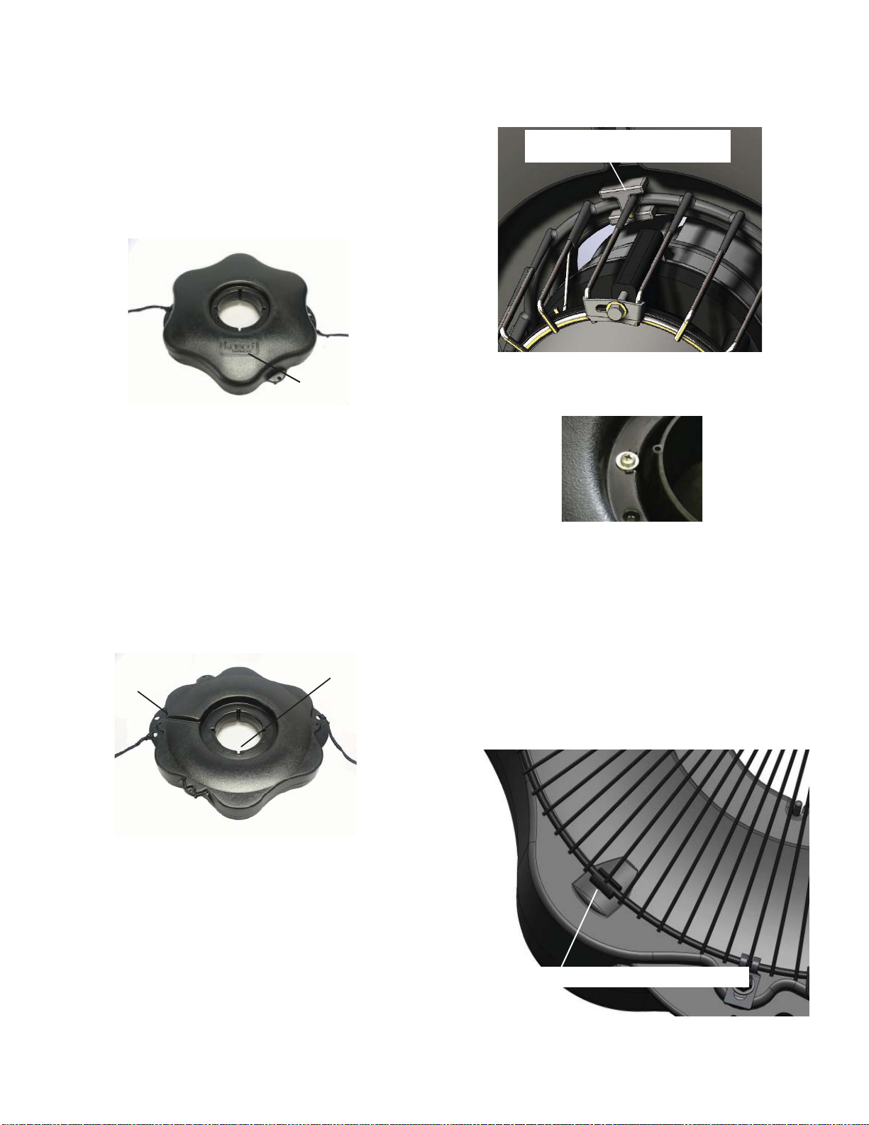
Rest the fl oat on the cage top ring.
STEP TWO
Ensure correct alignment by twisting the fl oat gently
around the motor housing until the power cord guide
lines up with the cord. See diagram of bottom side of
fl oat.
power cord
guide
Bolt holes
STEP THREE
Use one of the 1/4”-20 x 3-1/4” Phillips Pan Head
Screws (Part 3), one 1/4” split washer (Part 4), and a
1/4” Flat Washer (Part 5) to secure the fl oat. Make
sure the split washer goes between the bolt head and
the fl at washer. Insert screw with washer through bolt
hole in fl oat.
12
3400EJ, 4400EJ Assembly
STEP ONE
Set motor housing upright (stainless steel can down)
on a fl at surface. With motor housing upright, slide
Float (Part 2) over pump housing making sure the
surface with the Kasco logo is up.
Use one fl oat retaining clip (Part 8) under the top ring
of the cage. There is a U-shaped indent in the clip
that will fi t snug against the top ring of the cage. The
1/4”-20 x 3-1/4” will then thread into the retaining
clip.
ing clip
fl oat retain
7

Tighten until snug with a Phillips Head screw driver
and repeat for 3 remaining screws.
STEP FOUR
Turn secured assembly upside down so the top of the
fl oat (logo side) is face down on the fl at surface. Place
Bottom Screen (Part 10) onto the bottom side of the
fl oat. Make sure the wide opening of the screen is
against the fl oat and the 3 handles on the screen do not
interfere with the rope placements. Fit the 3 Bottom
Screen cushion (Part 9) underneath the screen and on
top of the 3 spacing bumps on the bottom of the fl oat.
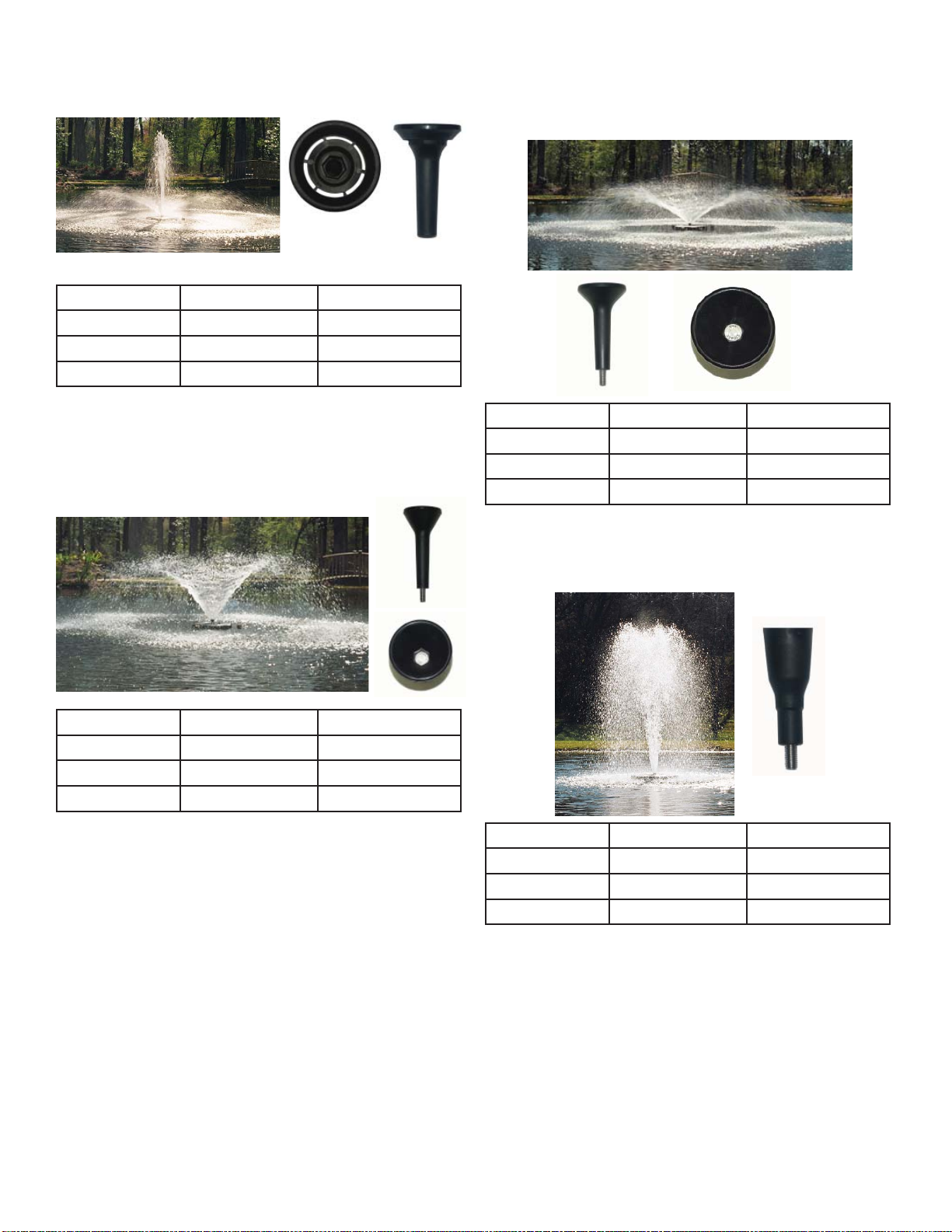
2400EJ, 3400EJ, 4400EJ Nozzle
Options
NOTE: Pattern sizes listed are approximate.
Variations in voltage caused by regional electrical differences or voltage drop due to long power cords may
result in reduced pattern sizes.
The Cypress is the only nozzle that uses the sepa-•
rate collar labeled C2.
The Cypress, Linden, Willow, and Juniper nozzles •
use the 3/8” x 4” bolt.
The Sequoia nozzle uses the shorter 3/8” x 2.25” •
bolt.
To install, simply drop the bolt through the nozzle and
thread into the top of the cone on the fountain.
Cypress Display: The Cypress nozzle (marked C1
on fi n) makes use of the collar (marked C2 on the top
rim) and the 3/8” x 4” bolt.
Bottom Screen cushion
STEP FIVE
Using a stainless steel Bottom Screen Clip (Part 11),
3/8”-16 x 1-3/8” Bolt (Part 6), two 3/8” Flat Washer
(Part 7), and 3/8”-16 Nylon Lock Nut (Part 12) to
secure the screen to the fl oat. Align a clip so the two
prongs straddle a wire on the screen. Insert bolt with
washer so the top of the bolt is facing the top of fl oat
(now in down position). Place the second washer and
the locking nut with nylon insert on the end of the bolt
and tighten using the 9/16” (14mm) Socket and Ratchet on the nut end and the 9/16” (14mm) Wrench on the
bolt end. Tighten until snug and repeat with remaining
clip.
Model Height Width
2400EJ 1.3 m 2.8 m
3400EJ 1.8 m 5.3 m
4400EJ n/a n/a
8
Linden Display: The Linden nozzle (marked
L inside one of the fi ns) uses the 3/8” x 4”
bolt.
Juniper Display: The Juniper nozzle (marked
with J on in inside of the nozzle cone) uses the
3/8” x 4” bolt.
Model Height Width
2400EJ 1.3 m 3.7 m
3400EJ 2.1 m 6.1 m
4400EJ 3.4 m 7.3 m
Willow Display: The Willow nozzle (marked
W on the inside of the cone) uses the 3/8” x 4”
bolt.
Model Height Width
2400EJ 0.9 m 3.5 m
3400EJ 1.4 m 5.3 m
4400EJ 2.4 m 7.0 m
Model Height Width
2400EJ 0.7 m 3.9 m
3400EJ 0.9 m 6.9 m
4400EJ 1.8 m 8.8 m
Sequoia Display: The Sequoia nozzle is not
marked and uses the shorter 3/8” x 2.25”
Model Height Width
2400EJ 1.6 m 1.0 m
3400EJ 2.2 m 1.5 m
4400EJ n/a n/a
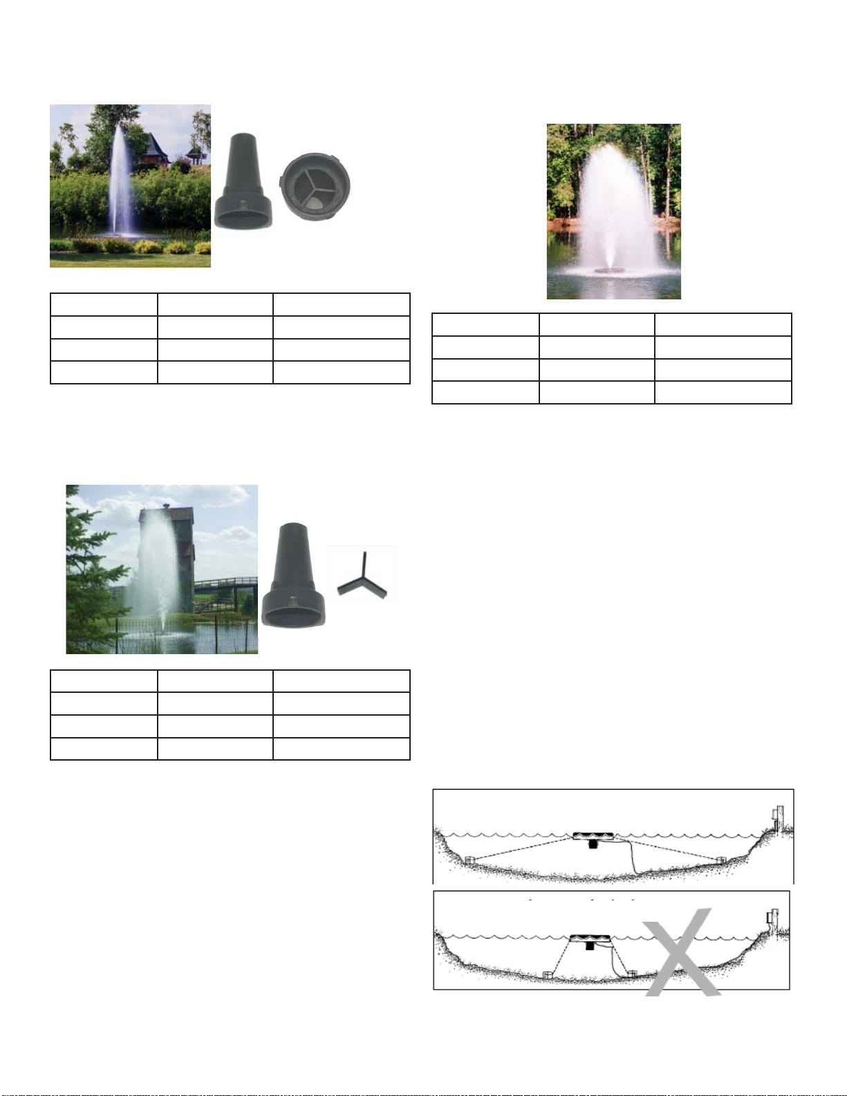
9
The Redwood nozzle uses the 3 self tapping screws to
attach over the pump housing and the Y Insert must be
installed.
The Birch display does not use a nozzle or bolt. It is
the fountain unit running without any nozzle and allows for the best fl ow rate and oxygen transfer!
Model Height Width
2400EJ n/a n/a
3400EJ n/a n/a
4400EJ 4.9 m 1.5 m
The Spruce nozzle uses the three self tapping screws
to attach over the pump housing and the Y Insert must
be removed.
Model Height Width
2400EJ n/a n/a
3400EJ n/a n/a
4400EJ 4.1 m 3.0 m
Model Height Width
2400EJ n/a n/a
3400EJ n/a n/a
4400EJ 2.6 m 1.8 m
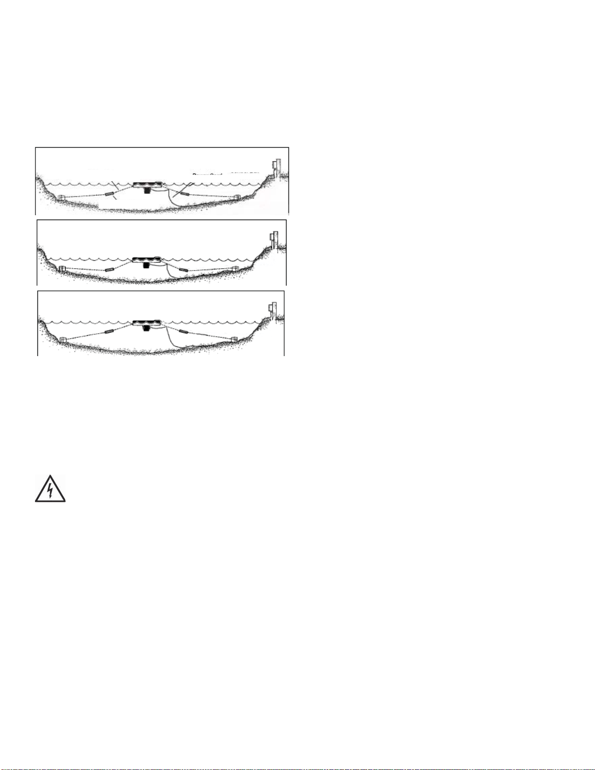
Installation Instructions
STEP ONE
Use the ropes to position the Unit in the desired location in the pond/lake (secure the cord near power
source to prevent it from being dragged into the water). Anchor the ropes or secure them to the shoreline
so the ropes are free of slack, but not tight. To prevent
twisting of the unit due to torque, you should place
the anchor at least 3m from the fl oat for each meter of
depth (Ex. A 3m deep pond would require an anchor
9m horizontally from the fl oat.) For ease of removal,
you may choose to keep at least one anchor within
reach from shore, just below the water’s surface.
Correct Anchoring
10
Incorrect Anchoring
STEP TWO (ALTERNATE INSTALLATION)
In ponds where the water level fl uctuates signifi cantly,
you may need to suspend a small weight (30cm of
2.54cm galvanize pipe works well) at the mid-point of
the rope to take up any slack as the water level drops.
The weight should be light enough so the Unit can rise
as the water level rises. This can also help hide ropes
by sinking them further below the surface.
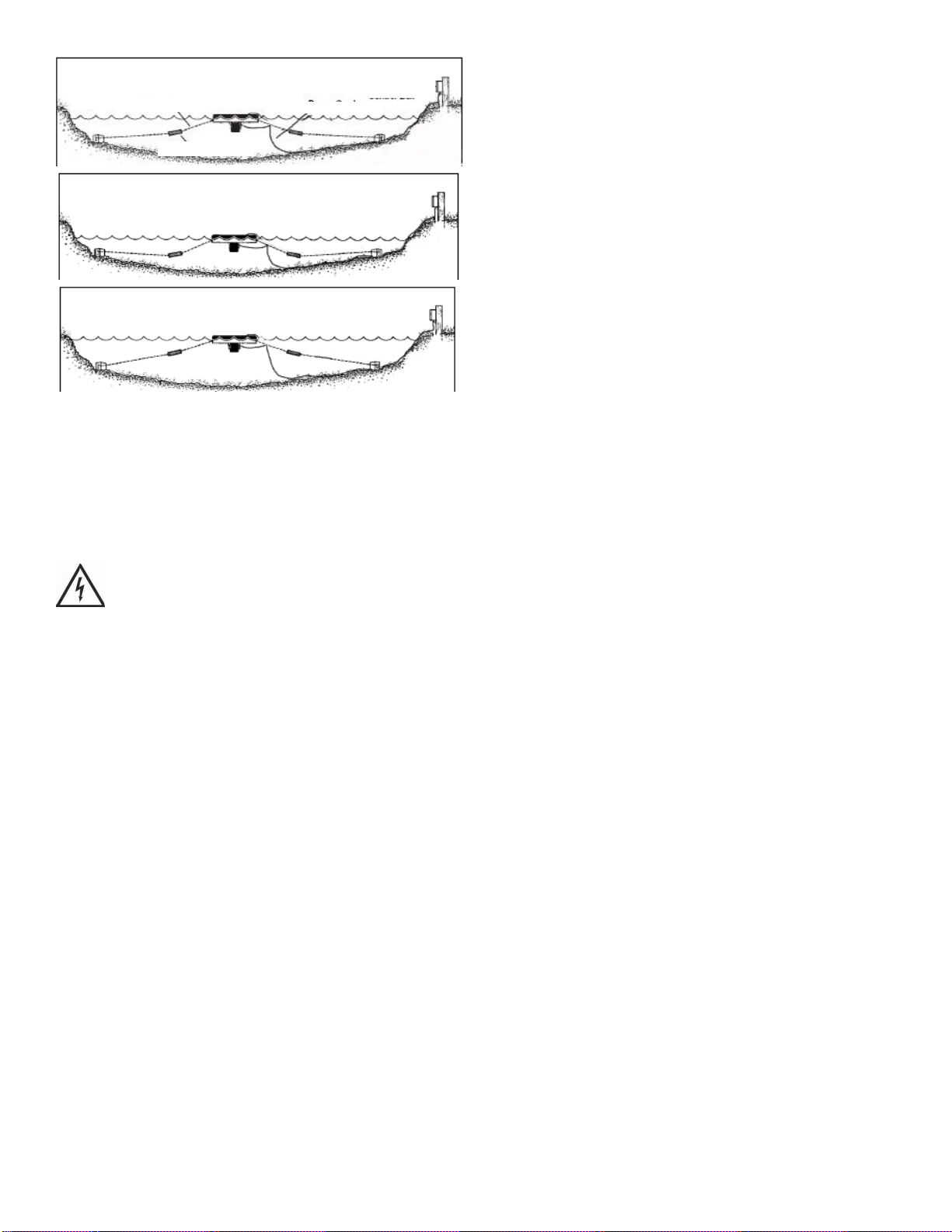
Normal W ater level
Anchor Rope
Secondary Weight
Low W ater Level
High W ater Level
Power Cord
Kasco Power
Control Box
STEP THREE
At this time the Fountain or Aerator is ready for operation. It can be plugged into the power supply at the
pond edge. ENJOY YOUR NEW KASCO EQUIP-
MENT!
Maintenance Recommendations
Under No Circumstances should anyone enter
the water while a fountain is operating. Turn Off and
Disconnect electrical power prior to any Maintenance
or Servicing
RCD (Residual Current Device) or GFCI are a safety
feature that can also alert you to electrical leaks in the
equipment. It is extremely important to test the RCD
upon installation, each reinstallation, and monthly
thereafter to ensure proper operation. If you have
repeat, consistent trips on your ground fault, the equipment should be disconnected and removed from the
water. The power cord should be inspected for damage and you should call a Kasco Marine distributor or
representative for further instructions.
If the supply cord becomes damaged, it must be
replaced by an authorized service center, or similarly
qualifi ed persons in order to avoid a hazard.
OBSERVATION: Operating equipment should be
observed on a regular basis (daily, if possible) for any
reduction or variation in performance. Disconnect
electrical power and inspect if any reduction in performance is noticed.
WINTER STORAGE: In regions where there is signifi cant freezing in the wintertime, Fountains should
be removed from the water to protect them from the
expansion pressure of the ice. Storage over winter is
best in a location that is out of the sun and cool, but
O
above 0
C.
CLEANING: Equipment should be removed from the
water at least once per year (at the end of the season
in cold climates) to clean the exterior of the system,
especially the stainless steel motor housing (can). The
motor housing is the surface that dissipates heat into
the water and any algae, calcium, etc. build-up will become an insulator that blocks heat transfer. In warmer
regions it is recommended that the motor is removed
and cleaned at least two to three times per year depending on conditions. In most cases a power washer
will be suffi cient if the unit and algae are still wet.
SEAL AND OIL REPLACEMENT: This is a sealed
motor assembly and seals will wear out over time
(similar to break pads on a car). Replacement of the
seals and a change of oil after three years may add
longevity to the operation of the motor, saving you the
cost of more expensive repairs. In warmer climates
where the equipment runs most or all of the year, it is
a good idea to replace seals more regularly than you
would need to in colder climates where the unit is
removed from the water for several months.
ZINC ANODE: A Sacrifi cial Zinc Anode is supplied
on the shaft of all Kasco 50Hz Fountains for protection of the equipment from corrosion and electrolysis. The zinc anode should be updated (replaced) if
reduced to half the original size or if white in color.
Corrosion from electrolysis is more commonly associated with saltwater or brackish water, but as a matter
of precaution, it is important to periodically check the
zinc anode in all installations (at least every two to
three months).
Seal replacement and all other repair services should
be performed by Kasco Marine or a Kasco trained
Authorized Repair Center.
Troubleshooting Tips
For more tips and information contact your Kasco
distributor or go to
www.kascomarine.com (Under the technical tab)
11

12
Kasco Marine, Inc.
800 Deere Rd.
Prescott, WI 54021
U.S.A.
Phone 00+1+715+262+4488
Fax 00+1+715+262+4487
www.kascomarine.com
sales@kascomarine.com
service@kascomarine.com
884151

Gebruikershandleiding
50 Hz-fonteinen
2400EVX, 3400EVX, 4400EVX
2400EJ, 3400EJ, 4400EJ
Inhoudsopgave
Belangrijke veiligheidsaanwijzingen . . . . . .2
Specifi caties van de units . . . . . .2
Installatie van de ‘Quick disconnect’-aansluiting . . . . . .2
Maten van draad en wartels . . . . . .4
2400EVX, 2400EJ, 3400EVX, 4400EVX Onderdelen . . . . . .5
Benodigd Gereedschap, Enz. . . . . . .5
Tabel met de afmetingen van EVX-patronen . . . . . .5
2400EVX, 2400EJ, 3400EVX, 4400EVX Montage-instructies . . . . . .5
3400EJ, 4400EJ Onderdelen . . . . . .7
Benodigd Gereedschap, Enz. . . . . . .7
3400EJ, 4400EJ Montage-instructies . . . . . .8
Sproeieropties voor model 2400EJ, 3400EJ, 4400EJ . . . . . .9
Installatieinstructies . . . . . .11
Aanbevolen onderhoud . . . . . .12
Tips voor het oplossen van problemen . . . . . .13
Kasco Marine, Inc.
800 Deere Rd.
Prescott, WI 54021
VS
Tel.: +1-715-262-4488
Fax: +1-715-262-4487
sales@kascomarine.com
www.kascomarine.com
Herz. 07/10/08
LET OP
KENNISGEVING (OPMERKING)
Deze internationale veiligheidssymbolen
worden overal in deze handleiding gebruikt
om de eigenaar attent te maken op belangrijke
veiligheidsinformatie en kennisgevingen
in verband met het veilige en doeltreffende
gebruik van de apparatuur.
De unit wordt geleverd met een interne •
aardleiding. Om het risico van elektrische
schokken te verminderen, dient u ervoor
te zorgen dat de unit op een goedgekeurde
stroomketen met aardlekschakelaar
(verliesstroomautomaat) wordt aangesloten.
De vaste bedrading moet voorzien zijn •
van een ontkoppelingssysteem, dat aan
zowel de plaatselijke als de nationale
bedradingsvoorschriften voldoet.
Raadpleeg een bevoegd elektricien voor de •
elektrische installatie.
Specificaties van de units
Belangrijke
veiligheidsaanwijzingen
LET OP
Personen mogen zich NOOIT in het water •
bevinden terwijl de elektrische apparatuur
aangesloten en/of in werking is. Het is NOOIT
verstandig om het water in te gaan terwijl de
apparatuur in werking is.
Ga altijd uiterst voorzichtig te werk tijdens •
het hanteren van elektrische apparatuur met
bewegende onderdelen.
Laat de unit NOOIT buiten het water draaien. •
Hierdoor worden de afdichtingen beschadigd en
wordt een gevaarlijke situatie geschapen voor
de operator.
Wees uiterst voorzichtig in de buurt van water, •
vooral koud water, bijv. in de lente, herfst en
winter, wat op zich al een gevaarlijke situatie is.
De unit mag NOOIT aan het stroom- of •
lichtsnoer worden opgetild of voortgetrokken.
Als u de unit naar de zijkant van de vijver
moet trekken, gebruik hiervoor dan de
verankeringskabels.
Gebruik nooit lieslaarzen in vijvers of meren •
die diep zijn, plotseling aanzienlijk dieper
worden of een sterk hellende bodem hebben of
een bodem die uit zacht materiaal bestaat.
Gebruik tijdens de installatie van uw •
fontein nooit een boot die gemakkelijk kan
omslaan (zoals een kano) en volg alle regels
en voorschriften voor veiligheid op het water,
inclusief het dragen van een reddingsvest
(‘Personal Flotation Device’ of ‘PFD’).
•
Model Voltage Bedrijfs-
stroom-
sterkte
2400EVX 208-240 2.2@220V 6@220V
3400EVX 208-240 3.6@220V 9@220V
4400EVX 208-240 5.9@220V 20@220V
2400EJ 208-240 2.2@220V 6@220V
3400EJ 208-240 3.8@220V 9@220V
4400EJ 208-240 6.5@220V 20@220V
Initiële
aanloopstroom
Installatie van de ‘Quick
disconnect’-aansluiting
Belangrijk – vóór de installatie aandachtig lezen
Alvorens met de installatie van de connector te
beginnen, dient u deze instructies aandachtig te lezen
en te begrijpen, zodat u het connectorsysteem volledig
waterdicht en elektrisch veilig kunt installeren. IN
GEVAL VAN TWIJFEL DIENT U EEN BEVOEGD
ELEKTRICIEN TE RAADPLEGEN.
De contrastekker (het vrouwelijke deel) van de
connector hoort rechtstreeks op de stroomvoorziening
aangesloten te zijn. De stekker (het mannelijke deel)
van de connector hoort aan het te voeden apparaat
vast te zitten. 50 Hz-units worden af fabriek geleverd
met de stekker (het mannelijke deel) van de connector
geïnstalleerd. Een goede afdichting is alleen mogelijk
als er gladde, ronde kabel wordt gebruikt.
2
Stekker van de connector (af fabriek geïnstalleerd
op het korte snoer)
Stekker
Wartel
Behuizing
Wartelmoer
Contrastekker (door gebruiker geïnstalleerd)
Contrastekker
Wartel
Behuizing
Wartelmoer
Opmerking:
Witte wartel voor buitendiameter van 9-11 mm
Gele wartel voor buitendiameter van 13-15 mm
Instructies voor samenstelling/bedrading
Verwijder de contrastekker uit de behuizing van de
connector. In het midden van de contrastekker zit een
sleuf voor een platte schroevendraaier.
Strippen van de draden
STAP 4
Steek de gestripte draaduiteinden in de contacten
achterop de contrastekker en draai de schroeven
volledig aan (zie afbeelding voor de juiste plaatsing
van de draden).
Afbeelding 5:
Aansluitingen van de draden
Bruine draad -- contact L
Blauwe draad -- contact N
Groen/gele draad -- contact E
Trek nadat u de draden
juist hebt aangesloten, de kabel met de contrastekker
erop weer in de behuizing en zet de contrastekker met
een schroevendraaier stevig vast.
Opmerking: de stekker en de contrastekker
hebben LINKS SCHROEFDRAAD; dus RECHTSOM
draaien om te verwijderen.
STAP 2
Haal de wartelmoer en de wartel uit de achterkant
van de behuizing en breng deze (de wartelmoer en de
wartel) op de kabel aan. Het trapvormige uiteinde van
de wartel moet naar de wartelmoer gericht zijn (zie
afbeelding).
Trapvormig uiteinde
STAP 3
Maak de kabel klaar door de draaduiteinden te
strippen zoals afgebeeld.
Opmerking: LINKS SCHROEFDRAAD; draai
de contrastekker dus LINKSOM vast.
STAP 5
Maak de bijgeleverde harsset klaar door het dopje van
het harsbuisje te verwijderen en het tuitje op het buisje
aan te brengen. Draai het tuitje vervolgens totdat het
vastklikt.
Plunjer Buisje met hars Tuitje
Druk alvorens de hars op de ‘Quick disconnect’aansluiting aan te brengen, de plunjer gelijkmatig
voldoende in om een kleine hoeveelheid hars te
spuiten; dit is nodig om de uit 2 componenten
bestaande epoxyhars naar behoren te mengen. Breng
vervolgens voldoende hars in de behuizing aan om de
draden en de contacten te bedekken. De hars moet
ongeveer 3 mm van de kabelmantel bedekken.
3
Opmerking: als er teveel hars wordt aangebracht, kan
het overschot in de contrastekker worden geperst,
waardoor de stekker er niet goed in zou passen.
Opengewerkte
afbeelding van
het vrouwelijke
gedeelte van de
‘Quick disconnect’aansluiting met
kleurloze hars. Let op
de hoeveelheid hars
op de kabelmantel.
STAP 6
Schuif de wartel en de wartelmoer langs de kabel in de
behuizing en draai de wartelmoer stevig vast. Hiervoor
is het niet nodig de epoxyhars eerst te laten drogen.
aansluiting te beschermen tegen beschadiging door
overmatige trekkracht. De trekontlasting moet op
het door de gebruiker verzorgde snoer worden
geïnstalleerd (niet op het door Kasco geleverde
korte snoer met de stekker). De trekontlasting moet
ongeveer 15 cm van de ‘Quick disconnect’-aansluiting
worden gemonteerd. Steek hiervoor het smalle
uiteinde van de lange klem met de ketting eraan
in het brede uiteinde van de korte klem. Gebruik
een rubberen hamer om deze twee stukken stevig
aan elkaar te bevestigen. Het geheel kan met een
nylon kabelbinder aan het snoer worden bevestigd.
Vervolgens kan de ketting aan het drijfl ichaam worden
bevestigd.
STAP 7
Wanneer deze helft van het ontkoppelingssysteem
klaar is, kunnen de twee helften op elkaar worden
aangesloten. Steek de stekker in de contrastekker en
draai de grote blauwe moer stevig vast. De blauwe
moer moet met de hand worden vastgedraaid. Zie de
onderstaande afbeelding.
Opmerking: nadat de blauwe is vastgedraaid, is er
hier een kleine ruimte zichtbaar
Als dit bij verwijdering aan het einde van het seizoen
gewenst is, kan de ‘Quick disconnect’-aansluiting
worden beschermd met de bijgeleverde waterdichte
afdekking. Maak hiervoor de ‘Quick disconnect’aansluiting los en breng de afdekking in de helft met
de grote blauwe moer aan. Draai deze vervolgens
stevig vast.
Maten van draad en wartels
De onderstaande tabel toont de wartels die met
verschillende snoermaten moeten worden gebruikt.
Deze maten zijn gebaseerd op de buitendiameter
van het snoer. Alleen glad, rond snoer moet worden
gebruikt.
Tabel met maten voor de Kasco 50 Hz-’Quick
disconnect’-aansluiting:
Wartel Buitendiameter snoer
Grijs 7-9mm
Wit 9-11mm
Zwart 11-13mm
Geel 13-15mm
Tabel draaddikten Kasco 50 Hz-apparatuur
Model Snoerlengte
10m 30m 60m 90m
2400EVX 1,5mm21,5mm22,5mm22,5mm
2400EJ 1,5mm21,5mm22,5mm22,5mm
3400EVX 1,5mm21,5mm22,5mm22,5mm
3400EJ 1,5mm21,5mm22,5mm22,5mm
4400EVX 1,5mm21,5mm22,5mm
4400EJ 1,5mm21,5mm22,5mm
2
4mm
2
4mm
2
2
2
2
2
2
Trekontlasting
De trekontlasting is nodig om de ‘Quick disconnect’-
4
2400EVX, 2400EJ, 3400EVX,
4400EVX Onderdelen
A. Fontein/beluchter, model EV of EJ (unit met snoer
of met kort snoer) (1)
B. Drijfl ichaam (voorzien van twee
verankeringskabels van 17 m (50 ft.)) 1
C. Cilinderkopschroef met kruiskop, 1/4-20 x 3 1/4
inch (83 mm) (4)
D. Vlakke sluitring, 1/4 inch (6 mm) (buitendiameter
3/4 inch – 19 mm) (4)
E. Vlakke sluitring, 3/8 inch (9,5 mm) (4)
F. Nylon borgmoer, 3/8-16 (2)
G. Zeskantkopbout, 3/8-16 x 1-3/8 (2)
H. Bevestigingsclips onderste scherm (2)
I. Nylon kabelbinder
J. Onderste scherm
K. Verwisselbare sproeiers, alleen voor model 2400EJ
(zie het gedeelte ‘Sproeieropties voor model
2400EJF’)
Tabel met de afmetingen van
EVX-patronen
Deze produceren allemaal een V-vormig patroon.
Model Hoogte Breedte
2400EVX 1,15 m 4,3 m
3400EVX 1,7 m 6,1 m
4400EVX 1,7 m 6,7 m
2400EVX, 2400EJ, 3400EVX,
4400EVX Montage-instructies
STAP 1
Overtuig u ervan dat u alle benodigde onderdelen
hebt. Als er onderdelen ontbreken, dient u
onmiddellijk contact op te nemen met uw Kascovertegenwoordiger.
Ook bijgeleverd: (niet afgebeeld)
L. Kussentjes voor de poten op de fonteinbehuizing (4)
M. Kussentjes voor onderste scherm (3)
N. Splitringen van 1/4 inch (6 mm) (4)
Benodigd Gereedschap, Enz.
A. Ankers of staken voor installatie van unit (2)
B. Kruiskopschroevendraaier nr. 2
C. Stroomvoorziening (208-240 V) nabij vijver, op
paaltje
D. Twee 30 cm lange stukken gegalvaniseerde buis
(doorsnede 2,54 cm) voor verzwaring van kabels
(facultatief)
E. Ratelsleutel met dopsleutel, 9/16 inch (14 mm)
F. Sleutel, 9/16 inch (14 mm)
STAP 2
Zet de motorbehuizing verticaal (met de roestvrij
stalen cilinder omlaag) op een plat oppervlak.
Verwijder de beschermlaag van de kleefl aag op één
van de kussentjes (onderdeel L) voor de poten op
de fonteinbehuizing. Breng het kussentje bovenop
de poot op de fonteinbehuizing aan en herhaal
deze procedure voor de overige drie kussentjes en
poten. Schuif het drijfl ichaam (onderdeel B) over
de pompbehuizing totdat het op de 4 poten op de
behuizing rust; zorg er hierbij voor dat het Kasco-logo
omhoog gericht is.
kussentje
logo
STAP 3
Zorg ervoor dat het geheel naar behoren past door het
drijfl ichaam voorzichtig rondom de motorbehuizing
te draaien totdat het ‘vastklikt’, de boutgaten in
5
het drijfl ichaam overeenkomen met die op de unit
en de sleuf op één lijn staat met het snoer. Zie de
onderstaande afbeelding van de onderkant van het
drijfl ichaam.
sleuf voor
snoer
boutgaten
STAP 4
Gebruik één van de cilinderkopschroeven met
kruiskop van 1/4-20 x 3 1/4 inch (onderdeel C), een
splitring van 1/4 inch (6 mm) (onderdeel N) en een
vlakke sluitring van 1/4 inch (6 mm) (onderdeel D)
om het drijfl ichaam te bevestigen. Let op: de splitring
hoort tussen de boutkop en de vlakke sluitring. Steek
de schroef met de pasringen door het boutgat in het
drijfl ichaam.
Kussentje voor het onderste scherm
Gebruik een roestvrij stalen bevestigingsclip
(onderdeel H), een bout van 3/8-16 x 1-3/8 (onderdeel
G), twee vlakke sluitringen van 3/8 inch (9,5 mm)
(onderdeel E) en een nylon borgmoer van 3/8-16
(onderdeel F) om het scherm op het drijfl ichaam te
monteren. Plaats de bevestigingsclip zodanig dat de
twee tanden zich aan weerszijden van een draad in
het scherm bevinden. Breng de bout met sluitring aan
met de kop naar de bovenkant van het drijfl ichaam
(die nu omlaag gericht is). Breng de tweede sluitring
en de nylon borgmoer op de bout aan en draai deze
vast (plaats hiervoor de ratelsleutel met dopsleutel van
9/16 inch (14 mm) op de moer en de sleutel van 9/16
inch (14 mm) op de kop van de bout). Draai het geheel
stevig aan en herhaal deze procedure voor de andere
clip.
STAP 5
Draai het gemonteerde geheel ondersteboven zodat
de bovenkant van het drijfl ichaam (met het logo) op
het platte oppervlak rust. Breng het onderste scherm
(onderdeel J) onderop het drijfl ichaam aan. Zorg
ervoor dat de brede opening in het scherm tegen het
drijfl ichaam aan staat en dat de 3 handgrepen op
het scherm de kabels niet belemmeren. Breng de
3 kussentjes voor het onderste scherm (onderdeel
M) onder het scherm aan en bovenop de 3 hiervoor
bedoelde verheffi ngen onderop het drijfl ichaam.
6
STAP 6
Zet de eenheid weer rechtop. Nu kunt u als het
snoer van een metalen trekontlasting voorzien
is de ketting hiervan in één van de gaten bij het
kabelbevestigingspunt aanbrengen. De ketting zal
gemakkelijk passen als deze vanaf de onderkant
of de bovenkant van het gat wordt aangebracht.
Vanaf de zijkant van het gat past hij niet. Gebruik de
bijgeleverde nylon kabelbinder (onderdeel I) om het
stroomsnoer in een gevormd gat in het drijfl ichaam
vast te zetten (dit om beschadiging van het snoer te
voorkomen als er geen trekontlasting op aanwezig
is). Als het snoer wel een trekontlasting heeft, kunt
u de nylon kabelbinder overslaan. Op snoeren met
een ‘Quick disconnect’-aansluiting moet deze naar
behoren worden aangedraaid om lekkage tegen
te gaan. Zie als u een nieuwe ‘Quick disconnect’aansluiting gaat installeren het gedeelte ‘Installatie van
de ‘Quick disconnect’-aansluiting’. Ga als u klaar bent
om de unit in de vijver te installeren, naar het gedeelte
‘Installatieaanwijzingen’.
3400EJ, 4400EJ Onderdelen
3
4
5
6
7
2
1
Fontein/beluchter (unit met snoer of met kort 1.
snoer) (1)
Drijfl ichaam (voorzien van twee 2.
verankeringskabels van 17 m (50 ft.)) 1
Cilinderkopschroef met kruiskop, 1/4-20 x 3 1/4 3.
inch (83 mm) (4)
Splitringen van 1/4 inch (6 mm) (4)4.
Vlakke sluitring, 1/4 inch (6 mm) (buitendiameter 5.
3/4 inch – 19 mm) (4)
Zeskantkopbout, 3/8-16 x 1-3/8 (2)6.
Vlakke sluitring, 3/8 inch (9,5 mm) (4)7.
Bevestigingsclips drijfl ichaam (4)8.
Kussentje voor het onderste scherm (3)9.
Onderste scherm10.
Bevestigingsclips onderste scherm (2)11.
Nylon borgmoer, 3/8-16 (2)12.
8
9
10
11
12
Benodigd Gereedschap, Enz.
A. Ankers of staken voor installatie van unit (2)
B. Kruiskopschroevendraaier nr. 2
C. Stroomvoorziening (208-240 V) nabij vijver, op
paaltje
D. Twee 30 cm lange stukken gegalvaniseerde buis
(doorsnede 2,54 cm) voor verzwaring van kabels
(facultatief)
E. Ratelsleutel met dopsleutel, 9/16 inch (14 mm)
F. Sleutel, 9/16 inch (14 mm)
7
Bevestigingsclip drijfl ichaam
3400EJ, 4400EJ Montage-
instructies
STAP 1
Zet de motorbehuizing verticaal (met de roestvrij
stalen cilinder omlaag) op een plat oppervlak. Houd
de motorbehuizing verticaal en schuif het drijfl ichaam
(onderdeel 2) over de pompbehuizing met het
oppervlak met het Kasco-logo omhoog.
bovenste ring van de korf aan. De clip is voorzien van
een U-vormige inkeping, waar de bovenste ring van de
korf in past. Draai vervolgens een schroef van 1/4-20
x 3 1/4 inch in de bevestigingsclip.
Bevestigingsclip drijfl ichaam
logo
Zorg ervoor dat het drijfl ichaam op de bovenste ring
van de korf rust.
STAP 2
Zorg ervoor dat het geheel naar behoren past door het
drijfl ichaam voorzichtig rondom de motorbehuizing
te draaien totdat het ‘vastklikt’, de boutgaten in
het drijfl ichaam overeenkomen met die op de unit
en de sleuf op één lijn staat met het snoer. Zie de
onderstaande afbeelding van de onderkant van het
drijfl ichaam.
sleuf voor
snoer
boutgaten
Draai de schroef met een kruiskopschroevendraaier
goed aan en herhaal deze procedure voor de overige 3
schroeven
.
STAP 4
Draai het gemonteerde geheel ondersteboven zodat
de bovenkant van het drijfl ichaam (met het logo) op
het platte oppervlak rust. Breng het onderste scherm
(onderdeel 10) onderop het drijfl ichaam aan. Zorg
ervoor dat de brede opening in het scherm tegen het
drijfl ichaam aan staat en dat de 3 handgrepen op
het scherm de kabels niet belemmeren. Breng de
3 kussentjes voor het onderste scherm (onderdeel
9) onder het scherm aan en bovenop de 3 hiervoor
bedoelde verheffi ngen onderop het drijfl ichaam.
STAP 3
Gebruik één van de cilinderkopschroeven met
kruiskop van 1/4-20 x 3 1/4 inch (onderdeel 3), een
splitring van 1/4 inch (6 mm) (onderdeel 4) en een
vlakke sluitring van 1/4 inch (6 mm) (onderdeel 5)
om het drijfl ichaam te bevestigen. Let op: de splitring
hoort tussen de boutkop en de vlakke sluitring. Steek
de schroef met de pasringen door het boutgat in het
drijfl ichaam.
Breng een bevestigingsclip (onderdeel 8) onder de
8
Kussentje voor het onderste scherm
Gebruik een roestvrij stalen bevestigingsclip
(onderdeel 11), een bout van 3/8-16 x 1-3/8 (onderdeel
6), twee vlakke sluitringen van 3/8 inch (9,5 mm)
(onderdeel 7) en een nylon borgmoer van 3/8-16
(onderdeel 12) om het scherm op het drijfl ichaam te
monteren. Plaats de bevestigingsclip zodanig dat de
twee tanden zich aan weerszijden van een draad in
het scherm bevinden. Breng de bout met sluitring aan
met de kop naar de bovenkant van het drijfl ichaam
(die nu omlaag gericht is). Breng de tweede sluitring
en de nylon borgmoer op de bout aan en draai deze
vast (plaats hiervoor de ratelsleutel met dopsleutel van
9/16 inch (14 mm) op de moer en de sleutel van 9/16
inch (14 mm) op de kop van de bout). Draai het geheel
stevig aan en herhaal deze procedure voor de andere
clip.
STAP 6
Zet de eenheid weer rechtop. Nu kunt u als het
snoer van een metalen trekontlasting voorzien
is de ketting hiervan in één van de gaten bij het
kabelbevestigingspunt aanbrengen. De ketting zal
gemakkelijk passen als deze vanaf de onderkant
of de bovenkant van het gat wordt aangebracht.
Vanaf de zijkant van het gat past hij niet. Gebruik de
bijgeleverde nylon kabelbinder om het stroomsnoer
in een gevormd gat in het drijfl ichaam vast te zetten
(dit om beschadiging van het snoer te voorkomen
als er geen trekontlasting op aanwezig is). Als het
snoer wel een trekontlasting heeft, kunt u de nylon
kabelbinder overslaan. Op snoeren met een ‘Quick
disconnect’-aansluiting moet deze naar behoren
worden aangedraaid om lekkage tegen te gaan. Zie
als u een nieuwe ‘Quick disconnect’-aansluiting gaat
installeren het gedeelte ‘Installatie van de ‘Quick
disconnect’-aansluiting’. Ga als u klaar bent om
de unit in de vijver te installeren, naar het gedeelte
‘Installatieaanwijzingen’.
Sproeieropties voor model
2400EJ, 3400EJ, 4400EJ
OPMERKING: De hier weergegeven
patroonmaten zijn bij benadering. Plaatselijke variaties
in de elektrische spanning en spanningsverliezen
vanwege het gebruik van lange stroomsnoeren kunnen
resulteren in verkleinde patronen.
De ‘Cypress’ is de enige sproeier waarbij de •
aparte ring met het label ‘C2’ moet worden
gebruikt.
Bij de sproeiers ‘Cypress’, ‘Linden’, ‘Willow’ en •
‘Juniper’ moet de bout van 3/8 x 4 inch (102 mm)
worden gebruikt.
Bij de sproeier ‘Sequoia’ moet de kortere bout van •
3/8 x 2,25 inch (57 mm) worden gebruikt.
U kunt deze monteren door de bout eenvoudigweg
door de sproeier heen te laten zakken en deze dan
bovenin de kegel op de fontein vast te draaien.
Patroon ‘Cypress’ (Cipres): Bij de sproeier ‘Cypress’
(met de markering ‘C1’ op één van de vinnen) horen
de ring (met de markering ‘C2’ op de bovenrand) en
de bout van 3/8 x 4 inch (102 mm) te worden gebruikt
Model Hoogte Breedte
2400EJ 1.3 m 2.8 m
3400EJ 1.8 m 5.3 m
4400EJ n/a n/a
9
Patroon ‘Linden’ (Linde): Bij de sproeier ‘Linden’
(met de markering ‘L’ op één van de vinnen) hoort de
bout van 3/8 x 4 inch (102 mm) te worden gebruikt.
Model Hoogte Breedte
2400EJ 1.3 m 3.7 m
3400EJ 2.1 m 6.1 m
4400EJ 3.4 m 7.3 m
Patroon ‘Juniper’ (Jeneverbes): Bij de sproeier
‘Juniper’ (met de markering ‘J’ aan de binnenkant van
de kegel) hoort de bout van 3/8 x 4 inch (102 mm) te
worden gebruikt.
Patroon ‘Willow’ (Wilg): Bij de sproeier ‘Willow’
(met de markering ‘W’ aan de binnenkant van de
kegel) hoort de bout van 3/8 x 4 inch (102 mm) te
worden gebruikt.
Model Hoogte Breedte
2400EJ 0.9 m 3.5 m
3400EJ 1.4 m 5.3 m
4400EJ 2.4 m 7.0 m
Model Hoogte Breedte
2400EJ 0.7 m 3.9 m
3400EJ 0.9 m 6.9 m
4400EJ 1.8 m 8.8 m
Patroon ‘Sequoia’: De sproeier ‘Sequoia’ is niet
gemarkeerd en hierbij hoort de kortere bout van 3/8 x
2,25 inch (57 mm) te worden gebruikt.
Model Hoogte Breedte
2400EJ 1.6 m 1.0 m
3400EJ 2.2 m 1.5 m
4400EJ n/a n/a
10
De sproeier ‘Redwood’ moet met de drie zelftappende
schroeven op de pompbehuizing worden bevestigd;
hiervoor is tevens het Y-vormige inzetstuk nodig.
Model Hoogte Breedte
2400EJ n/a n/a
3400EJ n/a n/a
4400EJ 4.9 m 1.5 m
De sproeier ‘Spruce’ moet met de drie zelftappende
schroeven op de pompbehuizing worden bevestigd;
hierbij moet het Y-vormige inzetstuk worden
verwijderd.
Model Hoogte Breedte
2400EJ n/a n/a
3400EJ n/a n/a
4400EJ 4.1 m 3.0 m
Voor het patroon ‘Birch’ wordt geen sproeier of
bout gebruikt. Hierbij werkt de fontein zonder
sproeier en zijn de optimale doorstroomsnelheid en
zuurstofoverdracht mogelijk!
Model Hoogte Breedte
2400EJ n/a n/a
3400EJ n/a n/a
4400EJ 2.6 m 1.8 m
Installatieinstructies
STAP 1
Breng de unit met de kabels op de gewenste plaats
in de vijver/het meer aan (maak het snoer bij de
krachtbron vast om te voorkomen dat dit in het water
wordt getrokken). Maak de kabels op zodanige manier
in de bodem of op de oever vast dat zij geen speling
hebben, maar ook niet te strak staan. Om verdraaiing
van de unit door wringkracht tegen te gaan, hoort u de
verankering voor elke m diepte ten minste 3 m van het
drijfl ichaam te plaatsen (bijv.: in een 3 m diepe vijver
hoort de horizontale afstand tussen de verankering
en het drijfl ichaam ten minste 9 m te bedragen). Om
verwijdering te vergemakkelijken, is het wellicht
verstandig om ten minste één verankering zodanig aan
te brengen dat deze vanaf de oever bereikbaar is (net
onder het wateroppervlak).
Juiste verankering
Onjuiste verankering
STAP 2 (ALTERNATIEVE INSTALLATIE)
In vijvers met een sterk variërend waterpeil is het
11
wellicht nodig een klein gewicht (een 30 cm lange
gegalvaniseerde buis met een doorsnede van 2,54
cm werkt goed) op het middelpunt van de kabels
aan te brengen om deze strak te trekken wanneer het
waterpeil daalt. Dit gewicht moet licht genoeg zijn
om de unit in staat te stellen om met het waterpeil
te stijgen. Dit kan de kabels ook verder onder het
wateroppervlak trekken om ze te verbergen.
Normaal waterpeil
Verankeringskabel
Secundair gewicht
Laag waterpeil
Hoog waterpeil
Stroomsnoer
Kasco-stroomkastje
of vertegenwoordiger van Kasco Marine voor verdere
instructies.
Mocht het stroomsnoer beschadigd raken, dan
moet dit worden vervangen door een geautoriseerd
servicecentrum of door een andere bevoegde partij
teneinde een gevaarlijke situatie te voorkomen.
OBSERVATIE: werkende apparatuur moet
regelmatig worden geobserveerd (liefst dagelijks,
indien mogelijk) op verminderde of variërende
doeltreffendheid. Als hierin enigerlei vermindering
wordt waargenomen, moet de stroomtoevoer
worden losgekoppeld en moet de apparatuur worden
geïnspecteerd.
WINTEROPSLAG: in gebieden waar het ‘s winters
vriest moeten fonteinen uit het water worden
verwijderd om ze te beschermen tegen de uitzetting
van het ijs. Voor de opslag tijdens de winter verdient
een koele plaats buiten direct zonlicht, maar met een
temperatuur boven 0
O
C de voorkeur.
STAP 3
Nu is de fontein of beluchter gebruiksklaar en kan hij
op de stroomvoorziening aan de rand van de vijver
worden aangesloten. WIJ HOPEN DAT U VEEL
PLEZIER BELEEFT AAN UW NIEUWE KASCO
APPARATUUR!
Aanbevolen onderhoud
Personen mogen zich NOOIT in het water
bevinden terwijl een fontein in werking is. Vóór het
verrichten van onderhoudswerkzaamheden moet de
stroomtoevoer worden uitgeschakeld en verbroken.
Een aardlekschakelaar (Residual Current Device
of ‘RCD’) of verliesstroomautomaat (‘Ground
Fault Circuit Interrupter’ of ‘GFCI’) is een
veiligheidsvoorziening die u attent kan maken op
elektrische lekken in de apparatuur. Het is uiterst
belangrijk om de RCD na de aanvankelijke installatie,
na elke herinstallatie en daarna eenmaal per maand
te testen teneinde te verzekeren dat deze naar
behoren werkt. Als er zich geregeld aardingsfouten
voordoen, moet de apparatuur worden losgekoppeld
en uit het water worden verwijderd. Controleer het
stroomsnoer op beschadiging en bel een distributeur
REINIGING: ten minste eenmaal per jaar moet de
apparatuur uit het water worden verwijderd (aan het
einde van het seizoen in koude klimaten), zodat de
buitenkant van het systeem kan worden gereinigd; dit
geldt vooral voor de cilindervormige roestvrij stalen
motorbehuizing. De motorbehuizing is het oppervlak
waardoor warmte in het water wordt losgelaten; als
er zich hierop algen, kalk, enz. ophopen, wordt deze
overdracht van warmte belemmerd. In warmere
gebieden verdient het aanbeveling de motor ten minste
twee à drie maal per jaar te verwijderen en te reinigen
(afhankelijk van de plaatselijke condities). In de
meeste gevallen is een power washer voldoende als de
unit en de algen nog vochtig zijn.
VERVANGING VAN AFDICHTINGEN EN OLIE:
dit is een motoreenheid met afdichtingen, die aan
slijtage onderhevig zijn (ongeveer zoals de remblokjes
van een auto). Door de afdichtingen en de olie na drie
jaar te vervangen, kunt u de levensduur van de motor
verlengen en u de kosten van duurdere reparaties
besparen. In warmere klimaten, waarin de apparatuur
het grootste deel van het jaar of het hele jaar in
gebruik is, verdient het aanbeveling de afdichtingen
vaker te vervangen dan in koudere klimaten, waarin de
unit gedurende enkele maanden niet wordt gebruikt.
12

ZINKELEKTRODE: om de apparatuur te beschermen
tegen corrosie en elektrolyse, zijn alle 50 Hzfonteinen van Kasco bij levering voorzien van een
oploselektrode van zink op de as. Als de zinkelektrode
tot de helft van de oorspronkelijke grootte is verkleind
of als deze wit is geworden, moet hij worden
vervangen. Hoewel corrosie door elektrolyse meestal
verband houdt met zout of brak water, is het bij alle
installaties belangrijk om de zinkelektrode voor de
zekerheid van tijd tot tijd (ten minste om de twee à
drie maanden) te controleren.
De vervanging van afdichtingen en alle andere
reparatiediensten horen te worden verricht door Kasco
Marine of door een door Kasco getraind, geautoriseerd
reparatiecentrum.
Tips voor het oplossen van
problemen
Voor meer tips en informatie kunt u terecht bij
uw Kasco-distributeur of op onze website: www.
kascomarine.com (tabblad ‘Technical’).
Kasco Marine, Inc.
800 Deere Rd.
Prescott, WI 54021
VS
Tel.: +1-715-262-4488
Fax: +1-715-262-4487
www.kascomarine.com
884151
13


Käyttöohjeet
50Hz suihkulähteet
2400EVX, 3400EVX, 4400EVX
2400EJ, 3400EJ, 4400EJ
Sisältö
Tärkeitä turvallisuusohjeita . . . . . .2
Tekniset tiedot . . . . . .2
Pikaliitinasetus . . . . . .2
Johtojen ja tiivisteiden koko . . . . . .4
2400EVX, 2400EJ, 3400EVX, 4400EVX Osat . . . . . .4
EVX-mallin koot . . . . . .5
2400EVFX, 2400EJF, 3400EVFX, 4400EVFX Kokoamisohjeet . . . . . .5
3400EJ, 4400EJ Osat . . . . . .6
3400EJ, 4400EJ Kokoamisohjeet . . . . . .7
Mallin 2400EJ, 3400EJ, 4400EJ suutinvaintoehdot . . . . . .8
Asennusohjeet . . . . . .10
Huoltosuosituksia . . . . . .10
Virheenkorjaus . . . . . .11
Kasco Marine, Inc.
800 Deere Rd.
Prescott, WI 54021
U.S.A.
Puh: 00+1+715+262+4488
Faksi: 00+1+715+262+4487
sales@kascomarine.com
www.kascomarine.com
Rev. 12/16/09
Tekniset tiedot
VAROITUS
HUOM.
Tässä käsikirjassa käytetään kansainvälisiä
turvallisuussymboleja kertomaan omistajalle
tärkeitä turvallisuustietoja ja huomautuksia
laitteen turvallisesta ja tehokkaasta käytöstä.
Tärkeitä turvallisuusohjeita
VAROITUS
Ketään ei MISSÄÄN NIMISSÄ saa päästää •
veteen sähkölaitteiden ollessa kiinnitettyinä/
käytössä. EI OLE KOSKAAN suositeltavaa
mennä veteen, kun laite on käynnissä.
Sähkölaitteita, joissa on liikkuvia osia, tulee •
käsitellä varoen.
ÄLÄ KOSKAAN päästä yksikköä tyhjenemään •
vedestä. Tämä vahingoittaisi tiivisteitä ja olisi
vaaraksi käyttäjälle.
Veden lähellä on toimittava varoen, etenkin •
kun vesi on kylmää, kuten keväällä, syksyllä ja
talvella, mikä on jo vaarallista sinänsä.
ÄLÄ KOSKAAN vedä tai nosta yksikköä virta- •
tai valojohdosta. Jos yksikkö on vedettävä
lammen rantaan, käytä kiinnitysköysiä.
Älä käytä kahlaussaappaita syvissä lammissa/•
järvissä, joissa on pudotuksia, jyrkkiä laskuja
tai pehmeä pohja.
Älä asenna suihkulähdettä helposti kaatuvasta •
veneestä, kuten kanootista. Noudata kaikkia
veneilyyn liittyviä turvallisuusohjeita ja
-sääntöjä, mukaan lukien pelastusliivien käyttö.
Yksikössä on sisäinen maadoitusjohto. Jotta •
sähköiskun vaara olisi pienempi, kiinnitä
yksikkö hyväksyttyyn RCD (GFCI) -suojattuun
piiriin.
Kiinnitetyn johdon liitosten tulee noudattaa •
paikallisia ja maan sääntöjä.
Piidä pätevältä sähköasentajalta neuvoa •
sähköasennuksessa.
Malli Jännite Virta Lukitun
roottorin
virta
2400EVX 208-240 2.2@220V 6@220V
3400EVX 208-240 3.6@220V 9@220V
4400EVX 208-240 5.9@220V 20@220V
2400EJ 208-240 2.2@220V 6@220V
3400EJ 208-240 3.8@220V 9@220V
4400EJ 208-240 6.5@220V 20@220V
Pikaliitinasetus
Tärkeää – lue huolella ennen asennusta.
Ennen kuin käytät liitintä, on tärkeää että olet lukenut
ja ymmärtänyt nämä ohjeet huolella, jotta voit olla
varma että liitinjärjestelmä on täysin vesitiivis ja
sähköturvallinen. JOS ET OLE VARMA, MITEN
TOIMIA, PYYDÄ NEUVOA PÄTEVÄLTÄ
SÄHKÖASENTAJALTA.
Liittimen istukan (naaras) on oltava se puoli, josta
sähkö saapuu. Liittimen pistokkeen (uros) on
johdettava kuormaan tai sähkölaitteeseen. 50 Hz:n
yksiköissä pistoke (uros) on asennettu tehtaalla. Jotta
liitos olisi tukeva, käytä ainoastaan tasaista pyöreää
kaapelia.
Pistoke (kiinnitetty johtoon)
Pistoke
Istukka (käyttäjän asentama)
Istukka
Runko
Runko
Tiiviste
Tiiviste
Tiivisteen
mutteri
Tiivisteen
mutteri
2
Huom:
Valkoinen tiiviste 9-11 mm:n ulkohalkaisijalle
Keltainen tiiviste 13-15 mm:n ulkohalkaisijalle
Kokoamisohjeet
ENSIMMÄINEN VAIHE
Irrota istukka liittimen kuoresta. Sen keskellä on lovi
ruuvitaltalle.
Huom: Osissa on VASEMMANPUOLINEN
KIERRE, ja ne irtoavat myötäpäivään kääntämällä.
ja kiristä ruuvitaltalla. Varmista, että osa on koottu
oikein.
Huom: VASEMMANPUOLINEN KIERRE,
kiristä kääntämällä vastapäivään.
VIIDES VAIHE
Valmistele hartsipakkaus poistamalla hartsituubin
korkki ja kiinnittämällä tuubiin suukappale. Kiristä
suukappale kääntämällä.
TOINEN VAIHE
Irrota tiiviste ja sen mutteri kuoren takaa ja pujota
ne johdon ympärille. Pidä huoli siitä, että suuntaat
tiivisteen mutterin porrastetun reunan kanssa (katso
kuvasta).
nut (see picture).
Porrastettu reuna
KOLMAS VAIHE
Valmistele johto ja kuori sen päät kuvan mukaisesti.
Johdon kuoriminen
Mäntä Hartsituubi Suukappale
Ennen kuin kiinnität pikaliittimen, työnnä ulos
pieni määrä hartsia niin, että saat oikean seoksen.
Levitä hartsia kuoreen riittävästi peittämään johdot
ja liitokset. Hartsin tulee ulottua noin 3 mm johdon
kuoren päälle. Huom: Jos levität liikaa hartsia,
ylijäämä saattaa joutua naarasliittimen sisään, jolloin
liittimet eivät pääse sulkeutumaan kunnolla.
Pikaliitos
kirkkaalla hartsilla.
Huomaa johdon
kuorta peittävä
määrä.
KUUDES VAIHE
Liu’uta tiiviste ja mutteri kuoreen ja kiristä mutteri.
Epoksin ei tarvitse antaa kuivua ennen kokoamista.
NELJÄS VAIHE
Laita kuoritut johdonpäät pistokkeen/istukan
takaosassa oleviin kiinnikkeisiin ja kiristä
kiinnitysruuvit. (Kuva esittää oikean kiinnityksen.)
Kuva 5:
Johtojen kiinnitykset
Ruskea johto kiinnikkeeseen L
Sininen johto kiinnikkeeseen N
Vihreä/keltainen johto
kiinnikkeeseen E
Kun johdot on
kiinnitetty kunnolla, vedä johto takaisin kuoren sisään
SEITSEMÄS VAIHE
Kun nämä osat on koottu, ne voidaan liittää yhteen.
Kiinnitä pistoke istukkaan ja kiristä sininen mutteri. Se
tulee kiristää vain kädellä. (Katso alla oleva kuva.)
3
Huom: Kiristämisen jälkeen osaan jää pieni rako
2400EJ 1,5mm21,5mm22,5mm22,5mm
3400EVX 1,5mm21,5mm22,5mm22,5mm
3400EJ 1,5mm21,5mm22,5mm22,5mm
4400EVX 1,5mm21,5mm22,5mm
4400EJ 1,5mm21,5mm22,5mm
2
4mm
2
4mm
2
2
2
2
2
Pikaliittimelle on tarjolla valinnainen vesitiivis
suoja, jos se irrotetaan joinakin vuodenaikoina. Irrota
pikaliitin, aseta suoja sinisen mutterin puoliskoon ja
kiristä.
Jännityksen poisto
Jännityksen poisto tulee asentaa suojaamaan
pikaliitintä liiallisen jännityksen aiheuttamalta
vahingolta. Se tulee asentaa käyttäjän hankkimaan
johtoon (ei Kascon toimittamaan johtoon). Se tulee
asettaa noin 15 cm päähän pikaliittimestä. Asenna
se asettamalla pitkän puristimen kapea pää lyhyen
puristimen leveään päähän kiinnitettyyn ketjuun.
Naputa nämä kaksi osaa tiukasti yhteen kumivasaralla.
Se voidaan kiinnittää johtoon nailonsiteellä. Ketju
voidaan sitten kiinnittää kellukkeeseen.
2400EVX, 2400EJ, 3400EVX,
4400EVX Osat
A. EV tai EJ ilmastava suihkulähde (johdollinen
yksikkö) (1)
B. Kelluke (jossa on 15 m:n kiinnitysköysi) 1
C. 1/4-20 x 3 1/4” tasakantainen ristipääruuvi (4)
D. 1/4” (3/4” ulkohalkaisija) litteä prikka (4)
E. 3/8” litteä prikka (4)
F. 3/8”-16 nailoninen lukitusmutteri (2)
G. 3/8”-16 x 1-3/8” heksakantapultti (2)
H. Pohjasihdin pidikkeet (2)
I. Nailoninen johtoside
J. Pohjasihti
K. Vaihdettavat suuttimet, vian mallille 2400EJF
(Katso kohta Mallin 2400EJF suutinvaihtoehdot)
Johtojen ja tiivisteiden koko
Alla oleva taulukko esittää, millaista tiivistettä
tulee käyttää minkä kokoisen johdon kanssa. Mitat
perustuvat johdon ulkohalkaisijaan. Johtojen tulee olla
sileitä ja pyöreitä.
Kasco 50 Hz pikaliittimen kokotaulukko:
Tiiviste Johdon ulkohalkaisija
Harmaa 7-9mm
Valkoinen 9-11mm
Musta 11-13mm
Keltainen 13-15mm
Kasco 50 Hz laitteen johdon kokotaulukko
Malli Johdon pituus
10m 30m 60m 90m
2400EVX 1,5mm21,5mm22,5mm22,5mm
2
Myös mukana: (ei kuvassa)
L. Lähteen kotelon jalkojen pehmusteet (4)
M. Pohjasihtin pehmusteet (3)
N. 1/4” prikat (4)
VAADITUT TYÖKALUT JA TAR VIKKEET
A. Asennusyksikön kiinnikkeet tai vaarnat (2)
B. # 2 ristipääruuviavain
C. 208-240V virranlähde lammen lähellä paalussa
D. Kaksi 30 cm:n palaa 2.54 cm:n galvanoitua
4
 Loading...