


De -Icing
De-Icer
Owners Manual
Contents
Safety Instructions . . . . . .2
Unit Specs . . . . . .2
De-Icer Sizing Chart . . . . . .2
General Owner’s Instructions . . . . . .2
De-Icer Installation Instructions . . . . . .3
Warranty Policy . . . . . .5
Maintenance Recommendations . . . . . .6
Troubleshooting Tips . . . . . .7
Replacement Parts Diagram . . . . . .9
Additional Accessories for Your De-Icer . . . . . .10
Customer Repair Form . . . . . .11
Registration Information . . . . . .12
C
Intertek
3020379
ANSI/UL 778, 5th Ed. 2010
CAN/CSA C22.2 No. 108-M89
UL 50, 11th Ed. 1995
Kasco Marine, Inc.
800 Deere Rd.
Prescott, WI 54021
U.S.A.
Phone 715-262-4488
Fax 715-262-4487
sales@kascomarine.com
www.kascomarine.com
824404
Rev. 05/22/12
Safety Instructions
Unit Specs
CAUTION
Under NO circumstances should anyone •
enter the water with the electrical equipment
connected and/or in operation. It is NEVER
recommended to enter the water with the
equipment in operation.
Caution should be used when dealing with any •
electrical equipment with moving parts.
NEVER run the unit out of water. It will •
damage the seals and create a dangerous
situation for the operator.
Extreme caution should be used around water, •
especially cold water, such as in Spring, Fall,
and Winter, which poses a hazard in and of
itself.
NEVER lift or drag the unit by the power or •
light cord. If you need to pull the unit to the
side of the pond, use the anchoring ropes.
Do not use waders in deep ponds/lakes or •
ponds/lakes with drop-offs, drastic slopes, or
soft bottom material.
Do not use boats that tip easily for unit •
installation, such as a canoe, and follow all
boating safety rules and regulations, including
wearing a PFD. (Personal Flotation Device)
The unit is supplied with an internal grounding •
conductor. To reduce the risk of electrical
shock, be certain that the unit is plugged/
connected to an approved GFCI protected
circuit.
Means for disconnection must be incorporated •
in the fi xed wiring in accordance with local and
national wiring rules.
Consult a qualifi ed electrician for electrical •
installation.
Note: Under certain conditions, no de-icer can
prevent damage from ice movement caused by wind or
current, or from extremely cold weather.
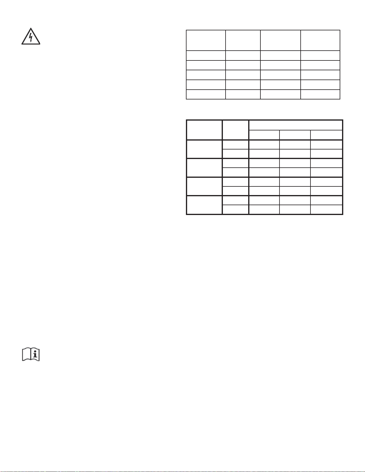
Model Voltage Operating
amps
lock rotor
amps
2400D 110-120 5.0 12
3400D 110-120 6.7 18
3400HD 208-240 3.4 9
4400D 110-120 11.3 40
4400HD 208-240 5.7 20
De-Icer Sizing Chart
Avg. Low
Air T emp
o
34
to
20oF
o
to 0
19
o
to 20
-1
Great
Lakes
Orientation
2400 3400 4400
angled 30’ x100’ 35’ x 120’ 40’ x 150’
vertical 65’ 85’ 95’
angled 25’ x 60’ 30’ x 80’ 34’ x 90’
o
F
vertical 50’ 70’ 80’
angled 25’ x 50’ 30’ x 75’ 35’ x 85’
o
F
vertical 45’ 65’ 75’
angled 20’ x 40’ 25’ x 50’ 30’ x 60’
vertical 35’ 45’ 55’
Assumptions for chart:
Unobstructed water•
200 acre plus body of water with 200 ft plus maxi-•
mum water depth or greater
Water depth in de-icing area 4 ft plus•
(Size may vary greatly based on a number of local
conditions)
Model
General Owner’s Instructions
INSPECT THE SHIPMENT
Immediately inspect your Kasco De-Icer shipment for
any visible damages. Also cross reference the parts
supplied with the Parts Included sheet to check for
shortages. Shortages should be reported immediately
to your Kasco Marine distributor or representative and
damages reported to your carrier and Kasco Marine.
CAUTION
WARNING: Under NO circumstances should anyone
enter the water with the unit in operation. Always
operate the unit in the water and keep people and objects clear of the propeller. Do not lift or pull the unit
by the electrical cord. Always use extreme caution
around electrical equipment and water situations.
2
ASSEMBLY & INSTALLATION
Please see the proper Assembly and Installation Instructions enclosed in this manual. Each is specifi c for
your model and size of De-Icer and De-Icer accessory.
WARRANTY
Kasco De-Icers are the result of over 40 years of
design and engineering. Kasco products are built to
withstand the toughest conditions. Kasco Marine
backs each De-Icer with a 2 Year Warranty. This warranty covers any and all manufacturers defects within
2 years from the date of purchase (See Warranty
Policy). Please register your De-Icer online at:
www.de-icer.com/solutions_warranty_registration.htm.
USE AND OPERA TION
Kasco De-Icers are designed and engineered for
continuous duty in the harshest environments, such as
in marinas or other commercial applications, or ondemand use, as may be needed.
easy to install and operate. We strive to produce products that exceed customer expectations. We hope you
enjoy your Kasco De-Icer.
Please Note: Under certain conditions, no de-icer can
prevent damage from ice movement caused by wind
or current, or from extremely cold weather causing ice
to form all the way to the bottom and in some cases
where bottom water temperature is the same as the ice.
Effective de-icing can also be retarded when used in
extremely shallow conditions.
UNIT STORAGE
When storing units during the offseason, it is important to store them upside down if they are going to be
sitting for long periods of time. Units that sit upright
on a shelf for many months, or even years have a
greater likelihood of seals drying out. Storing upside
down will ensure oil is lubricating the seals and prevent drying.
Your Kasco Marine De-Icer is ready for immediate use
(after installation). The motor is of an oil-fi lled design
with ball bearings submerged in oil and equiped with
a thermal overload protection with an automatic reset.
No further lubrication is necessary. It is extremely
important that the installer make sure suffi cient and
proper voltage is available to the unit’s motor. The
zinc anode located below the propeller must be in
good condition in order to prevent corrosion damage
to the unit. The zinc anode must be inspected periodically and replaced if it shows signifi cant deterioration.
Make sure to keep the motor housing clean from hard
water deposits and/or algae. (See Maintenance Recommendations on page 6.)
Note: If the De-Icer has been stored or exposed
to cold for an extended period without running, it may
take a minute for the prop to get to full speed once
power is supplied.
The De-Icer is also completely assembled, you do not
need bolts, screws, nails, or brackets, unless an optional mounting device was purchased. All you have
to do is suspend it in as little as two (2) feet of water
from piers, docks, or boats and plug it into a properly
grounded and GFI protected 15 amp outlet.
De-Icer Installation Instructions
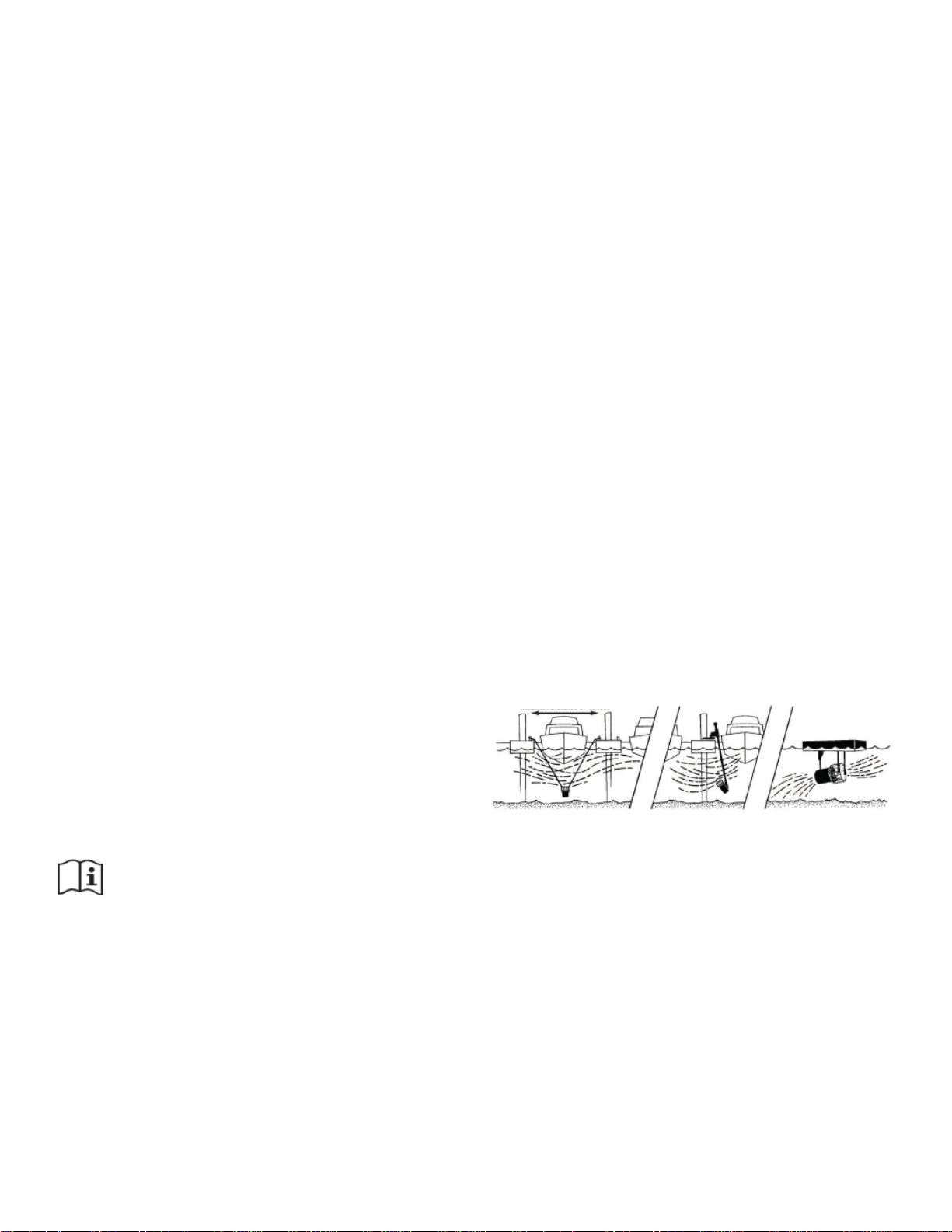
Kasco offers three basic ways for De-Icer installation:
Vertical Rope Suspension, Universal Dock Mounting
kit, or Angled / Horizontal Float Installation. Different
De-Icing objectives may require different mounting/
installation options.
Minimum Distance 8-10 feet
Vertical Suspension Universal Dock &
piling mount
Angle Operation
with Flotation Unit
STEP ONE
Locating a De-Icer depends on your De-Icing
objectives. If ice expansion pressure is your concern,
you may fi nd it easier to have an open-water buffer
between your dock or structure and the expanding ice
pack.
If ice lifting or a combination of lifting/expansion
is your concern, you may wish to keep your dock,
structure, or boat area completely ice free. These
objectives are different and may require different
installations.
Kasco De-Icers are lightweight, energy effi cient, and
3

Open water
buffer releases ice
Ice
Expansion
Pressure
Ice
collars
Tide
Jacked
pilings
Shore
Uneven
lifting is
common
Diven
pilings
expansion pressure
Kasco Horizontal
Flotation units
Suspended
Kasco Deicer
Shore
STEP TWO
Determine the best location(s) to install. A De-Icer
draws warmer, denser water from the bottom (4OC is
approximately water’s densest point) and circulates it
upward to the surface. Around docks and boats water
is usually fairly shallow, so look for somewhat deep
water to install your De-Icer. However, if your DeIcer is installed too deep, the rising warmer water will
not effectively spread at the surface, thereby reducing
the De-Icing effect.
you can choose your installation point(s). Some useful
tricks you may wish to consider are:
De-Ice from the upstream side and let the current •
help, rather than hinder.
Boats are designed to allow water to fl ow from •
the bow to the stern with the least resistance. It is
generally easier to De-Ice a boat by installing the
De-Icer at or near the bow, angled to push the DeIcing fl ow of water toward the stern.
It is generally easier to De-Ice a shallow area by •
bringing the warmer water from a deeper area into
the shallow area. Angle your De-Icer from the
deeper water toward the shallow water.
When using more than one unit, it is better to angle •
all units in one direction, creating a current rather
than installing De-Icers in opposing directions.
In tidal waters, split the difference in water depth •
so the De-Icer is in shallow water at low tide and
deep water at high tide. If you are De-Icing a boat,
it is easier to tie your De-Icer to the boat and allow
the boat and De-Icer to rise and fall with the tide
together.
High tide
Note: A good guide is 4-6 feet deep for vertical
installation, and slightly shallower for angled
operation, but at least 1 foot off the bottom to
prevent clogging from debris. In colder climates,
warmer water is a more important factor than surface
circulation, so you may wish to install your De-Icer
deeper than the above guide lines. De-Icers generally
will work in shallower water, but are less effective
and due to the constraints of your installation, you
may have to settle for a shallower installation. It is
recommended that you experiment with more than one
possible location for the best installation results.
STEP THREE
When you have determined both your De-Icing
objectives and best installation points, it is time to
analyze what external constraints your De-Icing
location (structures, i.e., dock, boat, etc.) may have
that could affect the fl ow of warmer water at the
surface. Any obstruction at the surface of the water
may slow or stop the fl ow of warmer water. A natural
current, such as in a river, will tend to force your DeIcing efforts downstream.
Once you have determined your external constraints,
Low tide
Deicer with Angle
suspension
Deeper
water
Boat house,
fl oating or
crib dock
Deicer
Shallow
water
Expansion Pressure
Deicer with Angle
Suspensions
Open
water
buffer
Possible
dock
mounted
Deicer
for longer
docks
STEP FOUR
When installing your Kasco De-Icer for suspended
operation with the provided ropes, make sure the ropes
or suspension lines are spread at least 8 to 10 feet
apart. The high starting torque of your Kasco De-Icer
may cause suspension lines that are too close together
to twist up and possibly damage the electrical power
cord. Tie each rope with a secure knot from the dock
piling, cleat, boat etc. so the De-Icer hangs vertically.
4
 Loading...