

Kasco 8400JF, 3.1JF, 5.1JF Owner's Instructions Manual
Owners Manual
J Series Decorative Aerators
Contents
Important Safety Instructions. . . . pg2
General Owner’s Instructions. . . . pg2
Unit Specs. . . . pg3
Parts Included. . . . pg3
Assembly Instructions. . . . pg4
Nozzle Options & Pattern Sizes. . . . pg7
Optional Premium Nozzles. . . . pg8
Installation Instructions. . . . pg9
Control Panel Installation. . . . pg10
C85 / C95 non-metallic Wiring Diagram. . . . pg12
3 Phase Startup Procedure. . . . pg13
C85 / C95 non-metallic and 3 Phase Control Panel Timer. . . . pg14
8400JF Replacement Parts. . . . pg15
2.3JF Replacement Parts. . . . pg16
3.1JF Replacement Parts. . . . pg17
3.3JF Replacement Parts. . . . pg18
5.1JF Replacement Parts. . . . pg19
5.3JF Replacement Parts. . . . pg20
7.3JF Replacement Parts. . . . pg21
Maintenance Recommendations. . . . pg22
Warranty Policy. . . . pg23
Troubleshooting Tips. . . . pg24
Customer Repair Form. . . . pg26
Registration Information. . . . pg28
C
Intertek
3020379
ANSI/UL 778: 2016
Ed.6+R:22Feb2017
CSA C22.2 #108: 2014 Ed.5
Kasco Marine, Inc.
800 Deere Rd.
Prescott, WI 54021
PH (715) 262-4488
FAX (715) 262-4487
www.kascomarine.com
Rev. 02/08/18

THANKS
We at Kasco Marine, Inc. would like to both thank and
congratulate you on your purchase of the JF model
decorative aerator. We appreciate you choosing Kasco
and for your purchase. Your decision to purchase Kasco’s Decorative Aerator will not disappoint you. The
JF Series Decorative aerator will be a great addition
to your body of water. It will help improve the water
quality by adding much needed oxygen and circulation. It will also enhance the aesthetics of the pond or
lake with beautiful patterns. The lighting package (if
purchased) will illuminate your aerator for beauty day
and night. We thank you for choosing Kasco for your
aerator needs and want you to be completely satised
with your purchase.
Important Safety Instructions
Please read and follow these extremely important
safety and handling instructions for your Kasco equipment. Following these instructions will help ensure
your safety and the quality performance of your equipment.
• Under NO circumstances should anyone enter the
water with the electrical equipment plugged in and/
or in operation. All Kasco equipment is ETL approved to UL and CSA standards for safety in water.
However, it is NEVER recommended to enter the
water with the equipment in operation.
• Caution should be used when dealing with any electrical and/or moving equipment.
• NEVER run the unit out of water. It will damage the
seals and create a dangerous situation for the operator.
• Extreme caution should be used around water, especially cold water, such as in Spring, Fall, and Winter.
Cold water poses a hazard in and of itself.
• NEVER lift or drag the aerator by the power or light
cord. If you need to pull the unit to the side of the
pond, use the anchoring ropes.
• Do not use waders in deep ponds/lakes or ponds/
lakes with drop-offs, drastic slopes, or soft bottom
material.
• Do not use boats that tip easily for aerator installation , such as a canoe, and follow all boating safety
rules and regulations, including wearing a PFD (Personal Flotation Device).
• Single phase aerators (8400, 3.1, and 5.1JF ) are supplied with an internal grounding conductor and/or a
grounding-type attachment plug. To reduce the risk
of electrical shock, be certain the aerator is properly
connected to the Kasco supplied control panel. (re-
fer to the C-85 & C-95 Control instruction)
• 3 phase aerators (2.3, 3.3, 5.3, 7.3JF) require a
startup test after wiring to ensure proper rotation of
the impeller. If the impeller is rotating in the opposite direction, the unit will not perform properly and
internal damage to the unit may occur. (See 3 phase
startup procedure)
• Control panels must be installed a minimum of
5ft(3m in Canada) from the inside wall of the pond,
unless separated from the body of water by a fence
wall, or other permanent barrier that will make the
unit inaccessible to persons in the water.
• Control panels must be installed by a qualied electrician.
• Ground Fault Circuit Interrupters (GFCI) should be
tested upon each installation and every month there-
after to ensure proper operation.
General Owner’s Instructions
INSPECT THE SHIPMENT
Immediately inspect your Kasco aerator shipment for
any visible damages. Also cross reference the parts
supplied with the Parts Included sheet to check for
shortages. Shortages should be reported immediately
to your Kasco Marine distributor or representative and
damages reported to your carrier and Kasco Marine.
ASSEMBLY & INSTALLATION
Please see the proper Assembly and Installation In-
structions enclosed in this manual. Each is specic
for your model and size of aerator. Note: Use a nylon
tie to help keep the power cords for the unit and lights
free of the impeller by tying each cord to either side of
the oat. If you have a light kit, make sure that the unit
cord is tied to one side of the oat and the light cord to
the other for balance. Note: It is extremely important
to test the GFCI in the control panel upon each installation/reinstallation of the unit to ensure proper functioning.
USE AND OPERATION
Kasco Aerators are designed and engineered for
continuous duty, such as on sh farms or other aquaculture applications, or on-demand use, as needed in a
recreational water feature.
During otation operation, the water is pulled from
O
360
around the unit and from below the unit. The
water is pulled upward and thrust through the otation
collar into the air.
2

Your Kasco Marine aerator is ready for immediate use
(after installation). Make sure to keep the motor housing clean from hard water deposits and/or algae. (See
Maintenance Recommendations)
It is extremely important that proper and sufcient
voltage is supplied to the aerator motor. Unit should
be protected by a GFCI. Control panels must be
installed by a qualied electrician. (See Installation
instructions).
Kasco aerators are lightweight, energy efcient, and
easy to install and operate. We strive to produce products that exceed customer expectations. We hope you
enjoy your Kasco aerator.
UNIT STORAGE
When storing units during the offseason, it is important to store them upside down if they are going to be
sitting for long periods of time. Units that sit upright
on a shelf for many months, or even years have a
greater likelihood of seals drying out. Storing upside
down will ensure oil is lubricating the seals and prevent drying.
Unit Specs
Single Phase
208-240 Volt
Voltage 208-240 208-240 208-240
Amps 10.5 13.4 20
Lock rotor
amps
Control box
connection
Aerator
connection
8400JF 3.1JF 5.1JF
40 61 97
C-85
Hardwire at
shore
plug or
hardwire
into C-85
C-95
Hardwire at
shore
plug or
hardwire
into C-85
Hardwire at
hardwire
into C-95
C-95
shore
Parts Included
8400JF, 3.1JF, or 5.1JF Aerator
2.3JF, 3.3JF, or 5.3JF Aerator
(Unit with cord or unit with Disconnect) (1)
A1. Cord in separate box (1) (depending on size of cord)
B. Float in separate box (1) (Diagram)
# Item Part # Qty
Float Sections (2, 3 HP only)
1a
Float Sections (5, 7.5 HP only)
1b
Top Float Bracket
2
Bottom Float Bracket w/Rope
3
9.5” x 3/8” Bolt
4
3/8” Lock Nut
5
Bottom Screen
6
Top Screen
7
Top Screen Clip
8
1/4-20 x 3/4” brass screw
9
1/4” Lock Washer
10
1/4” Nut
11
Bottom Screen Clip
12
3/8” x 1” Bolt
13
3/8” lock washer
14
Mesh screen
15
Cable ties for mesh
16
8400JF, 3.1JF, 2.3JF, 3.3JF parts diagram
284001 3
251001 3
840157 3
840158 3
840159 6
462214 6
990162 1
840175 1
223111 3
664750 3
840537 3
840536 3
223240 3
566250 3
566230 3
990170 1
415038 10
3 phase 208-
2.3JF 3.3JF 5.3JF 7.3JF
230 Volt
Voltage 208 208 208 208
Amps @208V 7.5 10.3 16.0 20.0
Lock rotor
40 70 100 100
amps
3 phase 460
2.3HJF 3.3HJF 5.3HJF 7.3HJF
Volt
Voltage 460 460 460 460
Amps 3.6 5.1 7.8 10.0
Lock rotor
24 40 49 50
amps
5.1JF, 5.3JF, 7.3JF parts diagram
3

Control Panel in separate box (1) (if purchased)
Set of Interchangeable Nozzles (5) (Diagrams)
# Item Part # Qty
1 #6 x 1/2” Self Tap Screw 820405 3
2 3/8” x 4” bolt 820090 1
3a Linden Nozzle (2, 3 HP) 820110 1
3b Linden Nozzle (5 HP) 820109 1
3c Linden Nozzle (7.5 HP) 703320 1
4a Redwood Y Insert (2 HP) (in #7) 820170 1
4b Redwood Y Insert (3 HP) (in #7) 820332 1
4c Redwood Y Insert (5 HP) (in #7) 820352 1
5 Juniper Nozzle 820140 1
6 Willow Nozzle 820150 1
7a Redwood/Spruce Nozzle (2 HP) 820160 1
7b Redwood/Spruce Nozzle (3 HP) 820330 1
7c Redwood/Spruce Nozzle (5 HP) 820350 1
8a Sequoia Nozzle (5 HP) 820130 1
8b Sequoia Nozzle (7.5 HP) 703200 1
9 3/8” x 2.5” Bolt 820095 1
8400JF, 3.1JF, 2.3JF, 3.3JF Nozzle Diagram
• #10 x 1” long or longer screw(s) for mounting the
control panel (4)
• 7/16” Socket & Wrench (1)
• 7/16” Wrench (1)
• 9/16” Socket & Wrench (1)
• 9/16” Wrench or adjustable crescent wrench (1)
• Flat head screw driver (1)
Assembly Instructions
1. Remove all contents from package and place on
a clean, at surface. Inspect the shipment for any
damages. If damages are found, immediately notify
your carrier and your Kasco Marine, Inc. representative. Next, cross reference the parts included in the
shipment with the Parts Included sheet in this manual.
Make sure you have all the parts needed. If any shortages are found, contact your Kasco representative
immediately.
2. Arrange the three Float Sections (Part #B1) upright
(plug on bottom) so the overlap of one section aligns
with the next section and loosely push the three sections together to form a continuous ring.
8400JF, 3.1JF, 2.3JF, 3.3JF
5.1JF, 5.3JF Nozzle Diagram
7.3JF Nozzles include linden and sequoia.
NOTE: Extra hardware may be included.
Tools & Supplies Needed
• Anchors or stakes for installing unit (3)
• Philips head screw driver for mounting C-85
• Electrical Supply near pond on a post with room
for mounting the control panel
• Three 12” galvanized pipe for weighting ropes
(optional)
4
5.1JF, 5.3JF, 7.3JF

3. Position one Top Float Bracket (Part #B2) so that
the bolt holes in the bracket align with the bolt holes
in the two adjoined oat sections and insert two 9.5”
Coated Bolts (Part #B4) through the assembly. This
may require some minor repositioning of the oat sections as you push the bolt all the way through. Do not
force the bolt through. Repeat for the remaining two
joints.
4. Turn the assembly upside down and place the Bot-
tom Float Brackets (Part #B3) over the bolts, the ends
of which should now be extending through the assembly. Loosely install the six 3/8” Lock Nuts (Part #B5)
on the ends of the bolts (do not tighten yet).
7. Take at mesh pattern and wrap into cone shape by
overlapping both vertical edges by approximately 1
inch and aligning top and bottom edges of mesh. Secure mesh vertical seam at the top, bottom and middle
using (3) cable ties.
Overlap vertical edges
5. Rest the oat on the base plate of the unit. Connect
the oat to the base plate using the 3/8” x 1” bolt (Part
#B13) and 3/8” lock washer (Part #B14). Tighten using a 9/16” wrench.
Attach 3 cable ties
1 inch overlap
6. Center the Top Screen (Part #B7) inside the three
Top Float Brackets. Attach the screen by spanning
each Top Screen Clip (Part #B8) across the two
innermost rings on the screen and the hole in the oat
bracket. Insert the 3/4” Brass Screws (Part #B9) and
attach with 1/4” Lock Washers (Part #B10) and 1/4”
Nuts (Part #B11) to secure the screen to the oat
assembly.
Place mesh cone on at surface with small diameter at
bottom. Insert existing stainless steel screen centered
inside mesh cone with approximately 2 inches of mesh
overlap to the top ring of the screen. Attach mesh
to the top ring of the screen in (3) equally spaced
locations using cable ties.
5
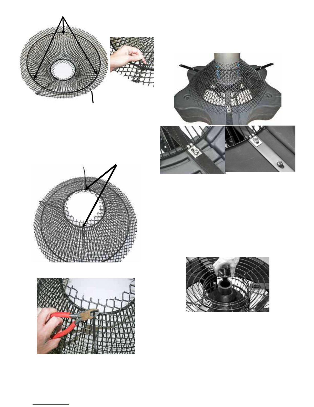
Attach 3 cable ties
to top ring equally spaced
2 inch overlap
Flip mesh and screen assembly over and use
remaining cable ties to secure mesh to small bottom
diameter of the stainless steel ring.
Attach 2 cable ties
to bottom ring equally spaced
Bottom Screen Clips (Part #B12) over the bolts as
shown. The power cord can be slid under the bottom
screen between the oat and screen where two oat
sections come together before the 3/8” Lock Nuts
are replaced. Replace the three inside Lock Nuts and
tighten all 3/8” Lock Nuts using the 9/16” wrench and
socket.
Clip off excess cable tie material once mesh is secured
into place.
8. Return the unit to its upright position and select a
nozzle (See Nozzle and Pattern Options). Insert the
Shaft Bolt (Part #D2) into the Nozzle Head so it ts
snugly into the molded socket for those nozzles that
use the bolt. Install the Nozzle by threading it into
the inner cone of the pump. Make sure to tighten the
Nozzle all the way down.
NOTE: If the nozzle does not look centered, see the
steps in the troubleshooting section for adjusting
the inner cone that the nozzle screws into.
Position the Bottom Screen (Part #B6) over the oat
so the motor housing (can) passes through the large
hole in the center of the screen. Remove the center
three 3/8” Lock Nuts from the 9” Bolts and place the
6
To install the Redwood nozzle, make sure the Y Insert
(Part #D4) is installed and seated properly into the
Nozzle Housing (Part #D7). Push the nozzle down
over the cone assembly (it may require light taps with
a rubber mallet to seat properly). Next, use the 3 Self
Tapping Screws (Part #D1) provided in the 3 holes on
the nozzle and tighten the screws into the cone assembly. Once you feel resistance, two more turns will
be sufcient. To install the Spruce nozzle, follow the
same steps, but do not install the Y Insert.
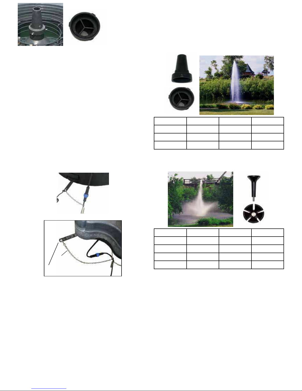
9. On power cord lengths of 100 feet or longer with
the watertight Quick Disconnect, the power cord is
shipped separately. It should now be attached to the
stub cord by lining up the male and female halves of
the disconnect and hand tightening the blue collar. On
these cords, the Additional Strain Relief should be
attached to one of the lower oat brackets as pictured.
If you receive a 3 chain strain relief (6 or 8 gauge
cord), attach one chain to each of the three lower oat
brackets. If there is not Strain Relief, use the Nylon
Cable Tie provided to secure the cord to a rope to
prevent damage by the propeller. Double check the
Quick Disconnect to make sure the threaded collar has
not come loose in shipping before placing in the water.
If installing a new Quick Disconnect, please refer to
Quick Disconnect instructions. Also, at this time,
lights can be installed if purchased.
• The Spruce nozzle must have the Insert removed
prior to nozzle placement.
• The Birch display does not require a nozzle.
The Redwood nozzle uses the 3 self tapping screws to
attach over the pump housing and the Y Insert must be
installed.
Model HP Height Width
8400, 2.3 2 22’ 7’
3.1, 3.3 3 24’ 8’
5.1, 5.3 5 26’ 8’
The Linden nozzle (marked L inside one of the ns)
uses the 3/8” x 4” bolt.
1 chain strain relief
Chain
Bottom Float Bracket
3 chain strain relief
Nozzle Options & Pattern Sizes
NOTE: Pattern sizes listed are approximate in feet.
Variations in voltage caused by regional electrical differences or voltage drop due to long power cords may
result in reduced pattern sizes.
• All ve (or six) nozzles are included with the
package.
• The Linden, Willow, and Juniper nozzles use the
3/8” x 4” bolt.
• The Sequoia (5.1JF only) uses the 3/8” x 2.5” bolt.
• The Redwood nozzle must have the Y Insert installed prior to nozzle placement.
Model HP Height Width
8400, 2.3 2 18’ 30’
3.1, 3.3 3 19’ 35’
5.1, 5.3 5 20’ 35’
7.3 7.5 24’ 28’
7

The Willow nozzle (marked W on the inside of the
cone) uses the 3/8” x 4” bolt
Model HP Height Width
8400, 2.3 2 12.5’ 28’
3.1, 3.3 3 13’ 35’
5.1, 5.3 5 14’ 36’
The Juniper nozzle (marked with J on in inside of the
nozzle cone) uses the 3/8” x 4” bolt.
The Birch display does not use a nozzle or bolt. It is
the aerator unit running without any nozzle and allows
for the best ow rate and oxygen transfer!
Model HP Height Width
8400, 2.3 2 12’ 11’
3.1, 3.3 3 14.5’ 10’
5.1, 5.3 5 14’ 12’
7.3 7.5 14.5’ 13’
The Sequoia nozzle (marked S on the inside of the
cone) uses the 3/8” x 2.5” bolt.
5.1JF, 5.3JF ONLY
Model HP Height Width
8400, 2.3 2 8’ 46’
3.1, 3.3 3 9’ 48’
5.1, 5.3 5 10’ 50’
The Spruce nozzle uses the three self tapping screws
to attach over the pump housing and the Y Insert must
be removed.
Model HP Height Width
8400, 2.3 2 19’ 10’
3.1, 3.3 3 21’ 13’
5.1, 5.3 5 24’ 15’
Model HP Height Width
5.1, 5.3 5 21’ 10’
7.3 7.5 26’ 10’
Optional Premium Nozzles
The following are optional premium nozzles available
for the J Series Decorative Aerators. Premium nozzles
offer splendid beauty above and beyond our included
patterns.
Madrone Premium Nozzle:
8
Magnolia Premium Nozzle:
Installation Instructions
Before installing 3 phase units (2.3, 3.3, 5.3, 7.3) into
the pond, please refer to 3 phase startup procedure.
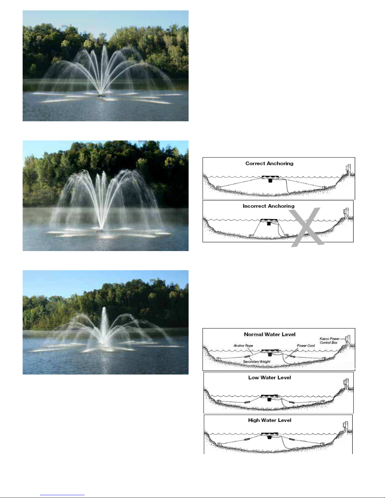
Use the ropes to position the aerator in the desired
location in the pond/lake. Anchor the ropes or secure
them to the shoreline so the ropes are free of slack, but
not tight. To prevent twisting of the unit due to torque,
you should place the anchor at least 3 feet from the
oat for each foot of depth (Ex. A 6 foot deep pond
would require an anchor 18 feet horizontally from the
oat.)
Palm Premium Nozzle:
Mahogany Premium Nozzle:
For ease of removal, you may choose to keep at least
one anchor within reach from shore, just below the
water’s surface.
(ALTERNATE INSTALLATION)
In ponds where the water level uctuates signicantly,
you may need to suspend a small weight (12” of 1”
galvanize pipe works well) at the mid-point of the
rope to take up any slack as the water level drops. The
weight should be light enough so the aerator can rise
as the water level rises. This can also help hide ropes
by sinking them further below the surface.
Contact your authorized Kasco distributor or visit
www.kascomarine.com for more information.
9
 Loading...