

Kasco 1400JFL User Manual
Owners Manual
1400JF & 1400JFL
Aerating Fountain
Contents
Safety . . . .pg2
General Instructions . . . .pg2
Parts & Tools . . . .pg3
Assembly & Installation . . . .pg4
Options & Pattern Sizes . . . .pg7
C-25 Timer Control . . . .pg8
Maintenance Recommendations . . . .pg9
Warranty . . . .pg10
Troubleshooting Tips . . . .pg12
Replacement Parts Diagram . . . .pg14
Customer Repair Form . . . .pg15
Registration Information . . . .pg16
C
Intertek
3020379
ANSI/UL 778, 5th Ed. 2010
CAN/CSA C22.2 No. 108-M89
UL 50, 11th Ed. 1995
Kasco Marine, Inc.
800 Deere Rd.
Prescott, WI 54021
PH (715) 262-4488
FAX (715) 262-4487
www.kascomarine.com
Rev. 05/22/12

Thanks
We at Kasco Marine, Inc. would like to both
thank and congratulate you on your purchase
of the 1400JF Aerating Fountain. We appreciate you choosing Kasco and for your purchase.
Your decision to purchase Kasco’s 1400JF
Aerating Fountain will not disappoint you.
The 1400JF Aerating Fountain will be a great
addition to your body of water. It will help
improve the water quality by adding much
needed oxygen and circulation. It will also
enhance the aesthetics of the pond or lake with
the 5 interchangeable fountain patterns. The
lighting package (if purchased) will illuminate your fountain for beauty day and night.
We thank you for choosing Kasco for your
fountain needs and want you to be completely
satisfi ed with your purchase.
Safety
Please read and follow these extremely important safety and handling instructions for your
Kasco equipment. Following these instructions will help ensure your safety and the quality performance of your equipment.
ter, especially cold water, such as in Spring,
Fall, and Winter, which poses a hazard in
and of itself.
NEVER lift or drag the fountain by the •
power or light cord. If you need to pull the
unit to the side of the pond, use the anchoring ropes.
Do not use waders in deep ponds/lakes or •
ponds/lakes with drop-offs, drastic slopes,
or soft bottom material.
Do not use boats that tip easily for fountain •
installation, such as a canoe, and follow all
boating safety rules and regulations, including wearing a PFD (Personal Flotation
Device).
The fountain is supplied with an internal •
grounding conductor and a grounding-type
attachment plug. To reduce the risk of
electrical shock, be certain that the fountain
is plugged into the C-25 Control Box supplied by Kasco and that the C-25 is plugged
into a properly grounded, grounding type
receptacle.
General Instructions
Under NO circumstances should anyone •
enter the water with the electrical equipment plugged in and/or in operation. All
Kasco 1400JF and 1400JFL equipment is
ETL approved to UL and CSA standards
for safety in water and all fountain models
included control panels with GFI protection. However, it is NEVER recommended
to enter the water with the equipment in
operation.
Caution should be used when dealing with •
any electrical and/or moving equipment.
NEVER run the unit out of water. It will •
damage the seals and create a dangerous
situation for the operator.
Extreme caution should be used around wa-•
2
INSPECT THE SHIPMENT
Immediately inspect your Kasco Fountain
shipment for any visible damages. Also cross
reference the parts supplied with the Parts
Included list to check for shortages. Shortages should be reported immediately to your
Kasco Marine distributor or representative and
damages reported to your carrier and Kasco
Marine.
CAUTION
WARNING: Under NO circumstances should
anyone enter the water with the unit in operation. Always operate the unit in the water and
keep people and objects clear of the propeller. Do not lift or pull the unit by the electri-

cal cord. Always use extreme caution around
electrical equipment and water situations.
ASSEMBLY & INSTALLATION
Please see the proper Assembly and Installation Instructions enclosed in this manual.
Each is specifi c for your model and size of
Fountain. Note: Use the nylon tie provided
to help keep the power cords for the unit and
lights free of the propeller by tying the cords
and one of the mooring ropes together. Note:
It is extremely important to test the GFI
breaker in the control panel upon each installation/reinstallation of the unit to ensure proper
functioning.
WARRANTY
Kasco Fountains are the result of over 35 years
of design and engineering. Kasco products
are built to withstand the toughest conditions.
Kasco Marine backs each 1400JF Fountain
with a 2 Year Warranty. This warranty covers any and all manufacturers defects within 2
years from the date of purchase (See Warranty
section). Please register your Fountain online
at:
www.kascomarine.com (under the Technical
Tab)
USE AND OPERATION
Kasco Fountains are designed and engineered
for continuous duty, such as on fi sh farms or
other aquaculture applications, or on-demand
use, as needed in a recreational water feature.
During fl otation operation, the water is pulled
from 360O around the unit and from below the
unit. The water is pulled upward and thrust
through the fl otation collar into the air.
further lubrication is needed. Make sure to
keep the motor housing clean from hard water
deposits and/or algae. (See Maintenance Recommendations)
It is extremely important that proper and suffi cient voltage (120V) is supplied to the Fountain motor. Each Fountain is supplied with a
UL and CSA approved C-25 GFI Protected
Control Box. The Fountain is to be plugged
into the C-25 outlet labeled “UNIT” and the
C-25 plugged into a properly grounded receptacle (See C-25 Instructions).
Kasco Fountains are lightweight, energy effi cient, and easy to install and operate. We
strive to produce products that exceed customer expectations. We hope you enjoy your
Kasco Fountain.
UNIT STORAGE
When storing units during the offseason, it is
important to store them upside down if they
are going to be sitting for long periods of
time. Units that sit upright on a shelf for many
months, or even years have a greater likelihood of seals drying out. Storing upside down
will ensure oil is lubricating the seals and
prevent drying.
Parts & Tools
1400JF Aerating Fountain (Assembled in •
box) (1)
NOTE: If lights are not purchased or included, the cord and Transformer on the left side of
the picture will not be included with the shipment.
Your Kasco Marine Fountain is ready for immediate use (after installation). The motor
and ball bearings are submerged in oil and no
3
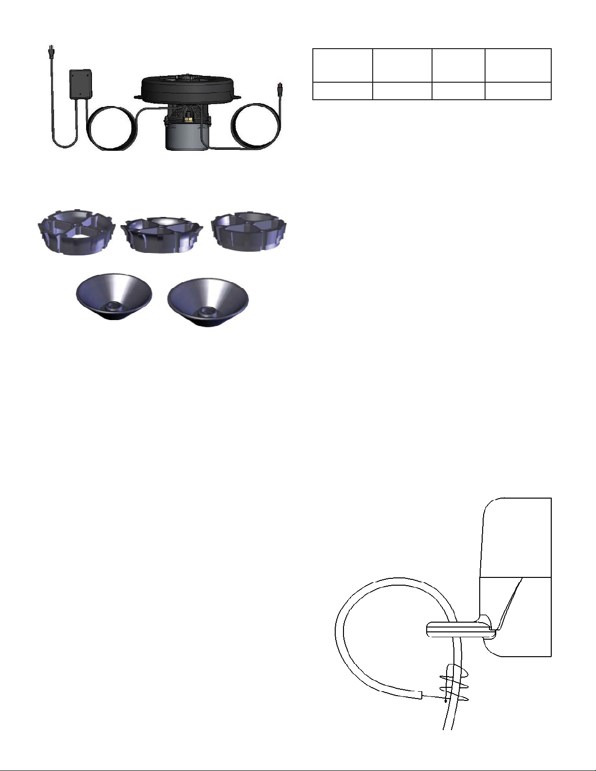
Interchangeable Nozzle Heads (Osprey •
Installed) (5)
Osprey #1
Eagle’s Nest #4
Condor #2
Hawk’s Nest #5
Falcon #3
UNIT SPECS
Model Voltage Amps Lock rotor
amps
1400JF 120 volts 3.1 10
Assembly & Installation
STEP ONE
Remove all contents from package and place
on a clean, fl at surface. Inspect the shipment
for any damages. If damages are found, immediately notify your carrier and your Kasco
Marine, Inc. representative. Next, cross reference the parts included in the shipment with
the Parts Included sheet in this manual. Make
sure you have all the parts needed. If any
shortages are found, contact your Kasco representative immediately.
Braided 15’ Nylon Mooring Ropes (2)•
1/4-20 x 7/8” Long Fillister head screw for •
Nest patterns (1)
C-25, 120V Control Unit (1)•
Nylon Cable Tie for securing cords and a •
mooring rope (1)
TOOLS & SUPPLIES NEEDED
Anchors or stakes for installing unit (2)•
Flat Head Screw Driver•
Philips head screw driver for mounting •
C-25 and Transformer (if lights are included) and installing nozzles
120V Electrical Supply near pond on a •
post with room for mounting the C-25 and
Transformer (if lights are included)
Two 12” pieces of 1” galvanized pipe for •
weighting ropes (optional)
#6 x 3/4” long or longer screw for mount-•
ing the Transformer (if lights are included)
(1)
#10 x 1” long or longer screw(s) for mount-•
ing the C-25 (3)
STEP TWO
Locate and unwind the two braided nylon
ropes included with the shipment. There are
two molded Rope Holes on opposite sides of
the fl oat attached to the fountain assembly. Tie
one end of a rope to one rope hole with a secure knot. Be sure not to leave too much of a
tail after the knot. Repeat with the other rope
on the other Rope Hole.
4
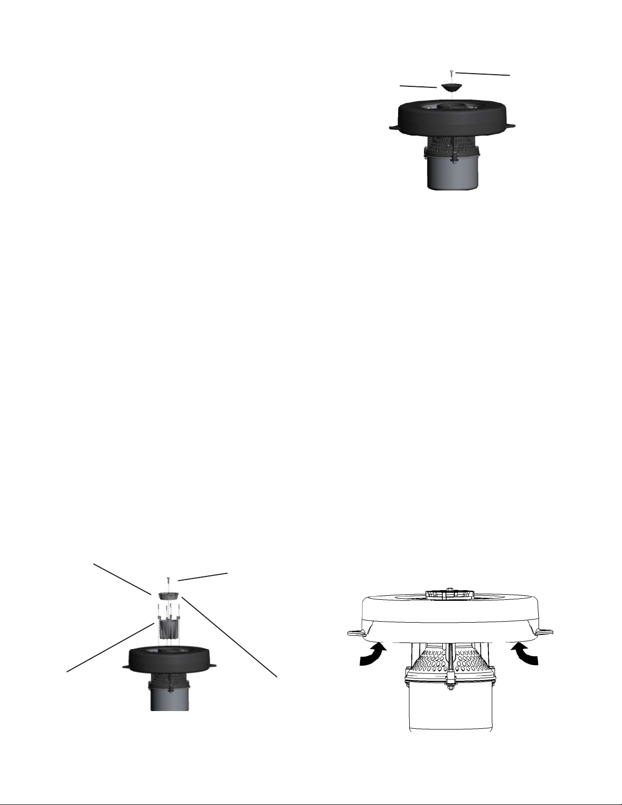
STEP THREE
Locate the 5 nozzles included with the shipment (the Osprey nozzle is already installed
on the fountain, along with the Upper Pump
Housing). Using the Nozzle Options diagram
on page 7, determine which pattern is desired
and the corresponding nozzle. If the Condor
or Falcon patterns are desired, you must remove the Osprey Nozzle by removing the 1”
Self Tapping Phillips Head Screw. Replace
the nozzle with either the Condor or Falcon,
re-insert the 1” Self Tapping Phillips Head
Screw and tighten until snug(Diagram A). If
either the Eagle’s Nest or Hawk’s Nest patterns are desired, you must remove the Upper
Pump Housing.
First, remove the 4 Upper Pump Housing
screws. With the Osprey nozzle still attached
to the Upper Pump housing, pull the osprey
nozzle and Upper housing up together. Finally, remove the 3/8” Fillister head, plastic
set screw in the top of the 4 Blade Prop. Place
a slight amount of pressure on the new nozzle
when in place and tighten the 1/4-20 x 7/8”
Fillister head screw until snug. Do not over
tighten. (Diagram B)
A
#6 x 3/4” Fillister
Head Upper Pump
Housing Screws
1” Self Tapping
Phillips Head Screw
B
1/4 –20 x 7/8”
Fillister Head
Eagle’s Nest Nozzle
Screw
STEP FOUR
Install the Fountain into the pond/lake in at
least 12” of water so the unit is fl oating freely.
Support the weight of the unit with the ropes
and/or the fl oat while setting it into the wa-
ter, DO NOT LIFT BY THE CORD. Use the
nylon tie to secure both cords and an adjacent
mooring rope together about 1 foot from the
fl oat to prevent twisting or getting caught in
the unit. Secure the ends of the cords to the
post at the power supply so the ends do not get
dragged into the water.
STEP FIVE
Determine how to anchor or secure the unit in
the pond. You may want to use weights at the
end of each rope (cinder blocks work well) and
sink them to the bottom or secure the ropes to
the shoreline by tying them to a stake or placing a rock on top of the ropes.
Upper Pump Housing
Osprey Nozzle
5
 Loading...