


21/08/2007
KAS
HS565 Mailmaster
Small touch screen (NT21)
OPERATORS MANUAL
HS565-NT21-Ops-V3.DOC3

CONTENTS: Page
Introduction - 2
1 Important Notes - 2
2 Operator Guide
2.1 Power Up - 3
2.2 Selecting End Feeders - 4
2.3 OMR Enable Setup - 5
2.4 System Setup - 6
2.5 Post Batch Setup - 7
2.6 Overhead Feeder Folder - 8
2.7 Test Mode - 9
2.8 System Status - 12
2.9 Operators’ Screen - 13
2.10 Data Log Control - 14
2.11 Clearing Machine - 15
2.12 Operator Help Pages - 17
2.13 Warning Pages - 19
3 Operator Adjustments
3.1 Feed Gate Setting - 21
3.2 Side Feeder Operations - 22
3.3 End Feeder Operations - 24
4 HS565 Sealer
4.1 Description - 25
4.2 Operator Adjustments - 25
5 Specifications - 28
6 Fold Options - 29

INTRODUCTION
The HS565 will operate as a standalone unit being hand fed or part of an automated feed
system. Documents pass along the main table collecting items from feeders where installed. An
envelope is fed from a hopper, down onto the moving table where it is filled with the document
(set). Once filled, the envelopes are counted, sealed and stacked on a conveyor.
The HS565 can run at a maximum speed of 7000 envelopes/hour.
1. IMPORTANT NOTES:
1. For the machine to operate correctly, after power up, it must be cycled using the
'Clear' facility on the System Setup screen. See 2.4.
2. The 'CLEAR' switch will only operate if all feeders are deselected and the on line
sensor is uncovered. See 2.11.
3. Before switching off the machine, all feeders should be deselected (by selecting
'CANCEL' from the System Setup menu) and emptied of paper (using the
'CLEAR' facility). It is recommended that the machine be cleared after each job is
completed.
4. 'TEST' can only be selected when the machine is not running. ‘ONLINE’ can be
used in test mode but not ‘END FEEDER’.
5. When 'Re-booting’ the power must be switched off for at least 30 seconds to allow
processor to clear.
Clearing Document Jams on the Moving Table
It should be noted that the moving table is secured under spring pressure, and in the event of
documents jamming in this area under normal operating conditions, the table may come to
rest under spring tension.
WARNING:
Do not attempt to remove documents until you have cycled the machine to its normal rest
position using the inch button. Failure to do so may cause the table to spring back quickly
into its correct position, when removing a wreck by hand.
When a document jam occurs and the documents are firmly trapped by the moving table the
inch button should be held until the table has completely opened before removing the
documents.
2

2. Operator Guide:
2.1 - Power Up:
Connect the IEC power lead to the switched inlet socket on the main connector panel. Switch
on and observe the KAS logo being displayed on the touch screen.
By touching the centre of the screen the System Setup menu will be displayed. See 2.4.
When installing a new End Feeder the switch should be used. This will display the
End Feeder Select screen (2.2), followed by the OMR Setup menus (2.3).
3

2.2 – Selecting End Feeders:
This menu is used to install the selected end feeder by pressing the appropriate switch and
seeing it illuminate. Pressing will then take you to the OMR Enable Setup menu. (See
2.3). If using a series of end devices, the device feeding the HS565’s on line position should be
selected, except when using a Fast Sheet Feeder and folder, select Fast Sheet Feeder + Set
Collector.
4

2.3 – OMR Enable Setup:
From this page, it is possible to enable or disable any of the request signals given by an
intelligent end feeder to feed documents from the side feeder stations. All signals are enabled
by default on power-up, apart from EOS (end of set), which remains in the last state set by the
user.
For example, if it is desired that Station 1 inserts requests should be ignored, the button
should be pressed to turn it off. All the buttons can be pressed or re-pressed to toggle the
status required. Black being ‘on’ white being ‘off’
Go to the System Setup menu. (See 2.4).
Go to the End Feeder Select menu. (See 2.2).
5

2.4 - System Setup:
The System Setup menu is used to enable the required feeders or modes of operation. It is not
possible to select 'ENDFEEDER' and 'ONLINE' together as both devices share the same input
position (3.3)
END FEED. Enables the device specified in the End Feeder Select menu (2.2)
ONLINE. Indicates that the end feeder to be used does not need synchronisation.
Toggles each side station on and off respectively.
CANCEL. Deselects all feed options, including CLEAR if it has been selected.
CLEAR. Used to empty the machine at the end of a run. It can only be selected when all
feed stations are deselected and the ‘ON LINE’ sensor position is empty. (See 2.11).
TEST MODE. Used to set the machine and run a test envelope with documents. (See 2.7).
POST BATCH SETUP. Displays the Post Batch Setup screen. (See 2.5).
END FEED SETUP. Used to return to the End Feed Select menu (See 2.2). This can
only be achieved if the machine is cleared first.
Go to the System Status screen. (See 2.8).
6

2.5 – Post Batch Setup:
The Post Batch Setup screen allows control over the exit conveyor.
Turns off all modes of conveyor batching.
Enables USER batch mode. This mode allows a batch count to be set via the batch
COUNT thumbwheel. When a batch is completed, the conveyor is indexed to separate the
completed batch from the following one.
Enables POST batch mode. This mode performs a batch operation according to
postcode signals received from and end feeder. At the appropriate time, the conveyor is
indexed to separate the completed postcode batch from the following one.
Enables BATCH STOP mode. This mode causes the machine to pause at the end of
each batch operation, requiring the start button to be pressed to restart the machine. This
mode can only be selected when either USER or POST batch mode is selected. When a batch
stop is in operation, the start button will flash.
Reset USER batch count. This can be used to reset the USER batch count at any time. It
will have no effect on POST batch operation. The current USER batch count can be seen below
the thumbwheel.
This thumbwheel allows adjustment of the conveyor index time for each individual
envelope, regardless of any batch mode in operation.
Go to the System Setup screen. (See 2.4).
7

2.6 – Overhead Feeder Folder Setup:
When the button on the System Setup page is pressed the above screen is displayed.
(On machines fitted with an overhead feeder folder in station one only. Machines without
this facility will not display this screen.)
If is pressed, the overhead feeder folder will run in OMR mode where printed,
allowing inserts to be selected from the side stations. This capability is not fitted as standard.
If is pressed, the overhead feeder folder will run in BATCH mode. This means that
the feeder will feed and fold a number of sheets according to the setting of the adjacent
thumbwheel. The minimum batch setting is 1 and the maximum is 5.
NOTE:
If the batch setting is greater than one and BATCH mode is selected, or if OMR mode is
selected, then the station cannot be deselected immediately by pressing CANCEL or the
station select toggle button. By pressing either of these, the station will continue feeding until
the current batch is completed (BATCH mode) or the current set is completed (OMR mode).
If the station is required to be cancelled regardless of the state of the current batch or set,
then it can be by pressing and holding CANCEL or the station select toggle button for one
and a half seconds. This will then force the station to be deselected.
8

2.7 - Test Mode:
Test mode is used to place one set of documents into an envelope, thus ensuring the machine is
set to produce correctly sealed envelopes. It can only be selected when the machine is not
running. The necessary side stations should be selected in the System Setup menu. ‘ONLINE’
should be selected in test mode if you require a document from the end feeder, not the end
feeder switch. After test mode has been completed the operator should then switch to end
feeder in order to run the machine.
In Test Mode Procedure the operator can choose whether to stop each document under its
double sensor or not.
Do not stop the machine to set the double switches.
Stop the machine at each selected side station to set its double switch.
Go to the Test Mode operation screen.
Go to the Test Mode End screen.
9

2.7 - Test Mode continued:
This screen shows a representational layout of the system feeders for test mode operation.
Each symbol represents a sensor that will flash if that fault occurs. Selecting will move
back to the Test Mode Control screen. Press (start) and the machine will begin to feed
one set of documents. (If ‘On-Line’ has been selected, a set of documents must be placed on
the end feed delivery table.)
If has been selected in Test Mode Control, the feeders will stop with one document
under the feed roller allowing the double sensor to be set. The corresponding lamp on the
screen will flash, indicating the appropriate sensor for adjustment. When the sensor requires
adjustment, the sensor indicator will light. When correctly set it will be off. Turn the
thumbscrew on the particular feeder anticlockwise until the double sensor indicator lights
(switch clicks). Then turn clockwise until indicator turns off (switch clicks). Then turn
further clockwise ¼ turn for single sheet 80gsm paper, or 1 turn for documents greater than
3mm. Once that sensor has been set, press (reset) and then (start) to continue
the test. Repeat this for each side station selected.
Pressing will allow an envelope to be fed without any inserts. This can only be done if
all stations are turned off.
A flashing lamp indicates that a specific error has occurred and this has to be rectified by
removing or inching the document. (Reset) can then be pressed to cancel
the flashing lamp and the (start) switch pressed to restart the machine. Test Mode will
end when one envelope has been filled with a set of documents and passed to the conveyor.
10

2.7 - Test Mode continued:
At the end of a test run, a Test Mode Complete screen will be displayed, see below, informing
the operator that they have the option to exit test mode or run another test.
Note:
Test Mode can be used as many times as necessary. It is advised to use Test Mode to check all
of the machine settings, i.e. paper track alignment, outfeed wheel setting, sealer stop
adjustment, etc. before your main run is commenced.
11

2.8 - System Status:
Flashes if a cover is lifted and the machine will stop if it is running.
SHEET STOP. This is used to send a signal to the end feeder to stop feeding.
SHEET START. This is used to send a signal to the end feeder to start feeding.
CYCLE START. This will start the machine.
CYCLE STOP. This will cause the machine to hold at the end of a cycle. It
will NOT stop the motor.
INCH. This will inch (jog) the machine.
Displays the Data Log Control screen. (See 2.10).
Displays the number of envelopes that have fed through the machine.
Displays the cycle speed of the machine.
Used to alter the speed of the machine. MIN – 0, MAX - 7.
Go to the System Setup screen. (See 2.4), or Operators screen (See 2.9)
12

2.9 - Operators’ screen:
The Operators’ screen shows a representational layout of the system in normal operator’s mode.
Each symbol corresponds to a sensor and will flash or remain lit if that error occurs.
Flashes if a cover is lifted and the machine will stop.
Flashes to warn the operator that the envelope feed hopper needs refilling. If the
operator ignores this warning, as the envelope hopper gets even lower, the flashing
warning light will be constantly illuminated and the machine will stop.
and lamps will be lit when a side station or an end device has been selected.
SHEET STOP. This is used to send a signal to the end feeder to stop feeding.
SHEET START. This is used to send a signal to the end feeder to start
feeding.
CYCLE START. This will start the machine.
CYCLE STOP. This will cause the machine to hold at the end of a cycle. It
will NOT stop the motor.
INCH. This will inch (jog) the machine. It is used to inch the machine to
clear paper wrecks etc.
RESET. This will cancel any error symbol once the error has been rectified.
Go to the System Status screen. (See 2.8).
Displays the first page of a series of operator help pages. (See 2.12).
13

2.10 – Data Log Control:
Reset the displayed envelope total count.
Displays the total envelopes that have run through the machine.
Enter the user data log pages that display runtime information.
Display a screen requiring the operator to confirm that he wishes to clear the
data log or not.
Go to the System Status screen. (See 2.8).
Data Log screens:
14

2.11 - Clearing Machine:
From the System Setup screen the machine has the facility to be emptied or cleared.
The switch is used for this at the end of a job run. It can only be selected if all feed
stations have been deselected using the cancel switch and the on line sensor is empty.
In this condition, will change the screen to the Machine Clearing screen, as shown below:
CYCLE START. This can be used to start the machine if it is not running.
Flashes if a machine cover is open.
Go to the System Setup screen. (See 2.4).
If an error occurs during clearing the Operators’ screen will be displayed showing a
particular fault and the machine will stop as in normal run.
15

2.11 - Clearing Machine continued:
At the end of the clear cycle, the screen will change to the Machine Empty screen:
Displays the ‘envelopes processed’ counter. (Also displayed on the ‘System
Status’ screen).
Purges the conveyor and then returns you to the System Setup menu screen. (See 2.4).
16

2.12 - Operators Help pages:
17

2.12 - Operators Help pages continued:
18

2.13 - Warning pages:
If the above screen is displayed, the problem is likely to be the control cable to the feeder is
loose, damaged or not connected. Rectify as necessary and press the switch.
NOTE: If this screen should show (PLC battery low), please contact your KAS agent.
19

2.13 - Warning pages:
If this screen appears, the End Feeder device will be in error or the safety cover has been
opened. Once the End Feeder has been rectified press to continue.
20
Screw
3 OPERATOR ADJUSTMENTS
3.1 Setting and Replacing the Feed Gate Rubber
The feed gate rubber is a solid cylinder of rubber held in place above the stripper roll. Its
purpose is to only allow one document at a time to pass through the feed rollers and onto the
machine track. It should be rotated to place a fresh section of rubber facing the feed roller
every 10,000 to 20,000 feeds, depending on the abrasive nature of the paper being used.
Remove the front plate by loosening the top screw, and removing the bottom screw with a
4mm Allen key. Remove the front plate and rubber. Rotate the feed gate rubber to a new
position, refit, and secure the front plate.
Note: When the rubber has been rotated completely it should be replaced.
After rotating or replacing the rubber, the feed gate should be reset as follows.
Using one thickness of document to be fed place it between the feed gate rubber and the feed
gate roller, and set a loose friction gap with the adjustment screw.
Note: It may be necessary to make small adjustments every 5 to 6 thousand feeds.
Top
Screw
Bottom
Adjustment
Screw
Front
Plate
Feed Gate
21

3.2 Side Feeder Operations
When selected, documents are fed from the relevant side feeder stations onto the main track.
The ‘Flighted belts’ push the documents towards the envelope section and at the relevant
time an envelope is fed from the hopper onto the moving table. The documents are pushed
into the envelope by two inserting fingers and then continue to the outfeed section where the
envelope is moistened, closed and placed onto the outfeed conveyor.
Double sensor adjustments (2.7), feed gate rubber adjustments (3.1) and fold plate
adjustments (where fitted) should be made before commencing the main run. If booklets are
to be fed, these are placed in the feeder nearest the envelope section, and the booklet
thumbscrew should be adjusted accordingly.
Station 1 Fold Plates. (Where fitted)
There are two fold plates located on station 1, under the plastic guards to the rear of the paper
hopper. The upper fold plate is used for C5 and DL folds. The lower fold plate is used for the
second DL fold only. The fold plates are held in place by two thumbscrews, one to each side.
When not in use, they can be rotated to allow documents to pass through without being
folded.
Top Fold Plate
Bottom Fold Plate
(seen from above)
Each plate has a fold stop bar which can be adjusted to the required fold position. Release the
two thumbscrew clamps and slide the bar up or down, scales are provided as a guide. When
adjusting the bar, care should be taken to keep it straight so that the edges of the paper are
level when folded.
Scales
Fold Stop Bar
Thumbscrews
Details of folds that can be achieved are found in section 6 of this manual.
22

Book Feeder
Th
umbscrew
All KAS Side Feeders are equipped with one book feeder. This feeder has a range of feed
thicknesses from one sheet to 5mm.
Setting Book Feeder
Set the feed gate (3.1) to the correct document thickness and fill the hopper. Select the
correct stations in test mode (2.7), and select YES to set the ‘double sensors’. If a thick
booklet is being fed from the booklet feeder, it may be necessary to open the feed rollers first
to allow the booklet to pass between them. This can be achieved by turning the booklet
thumbscrew clockwise until a gap is visible between the two rollers. Once a booklet is
between the rollers, the booklet thumbscrew can be turned anticlockwise, until the rollers
meet the booklet. The double sensor may now be set in the normal way. Continue with the
test procedure. When the test run is complete, rotate the booklet thumbscrew anticlockwise
by one turn .
Note: When setting back to a thin document the booklet and double adjustment screws
should be turned anticlockwise in unison as they interact with each other.
Double Sensor
Thumbscrew
Booklet
23

3.3 End Feed Operations
All KAS end feeders are synchronised to the HS565 via the 23-pin control plug and socket on
the main connector panel. If another end feeder is used it may be connected to the 23-pin
socket depending on customer application.
12 Pin Socket
Switched
Power
23 Pin Socket
If no or limited synchronisation between end feeder and the HS565 is required the feeder
should be connected to the 12 pin socket. Wiring will be supplied where needed.
The ‘On Line’ sensor is located at the far end of the machine to the envelope section,
underneath the end smoothers. Documents are received from an end feed device or hand fed
onto this position.
For further end feeder operations, see the relevant end feeder manual.
On Line Sensor
Position
24

4 HS565
Thumbscrew
4mm Screws
4.1 Description
Documents are placed onto the track from end feeder and sidefeeder positions. They continue
along and at the relevant time a corresponding envelope is fed from the envelope hopper,
down and onto the moving table. The documents are then pushed into the envelope by two
inserting fingers and the filled envelope is passed through the machines outfeed section,
where it is diverted sideways under the envelope flap wetting brush to moisten the glue. The
flap is closed and the completed envelope is placed onto the conveyor.
.
4.2 Operator Adjustments
4.2.1 Envelope Backpost
The envelope hopper operates on the same principal as a sidefeeder hopper. The two feed
gate rubbers and side guides should be set (using the guide scales provided) before placing
the backpost in the correct position and attaching it with the thumbscrew.
Feed Gates
Envelope
Backpost
Side Guides
Backpost
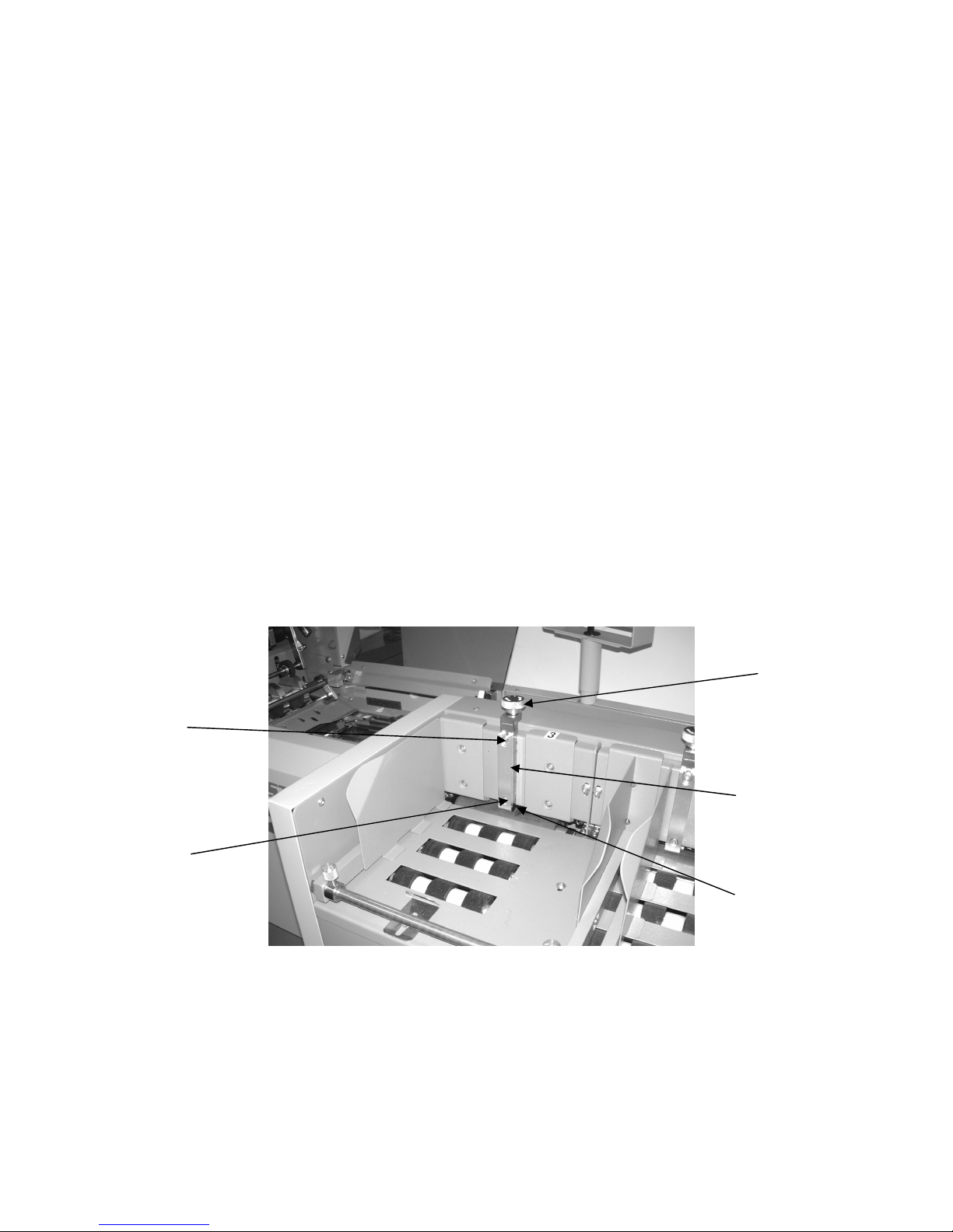
4.2.2 Hookwheel Backplate
Depending on the size of envelope flap, the backplate can be moved up or down. This is to
achieve the correct envelope position on the moving table. Loosen the two top 4mm cap head
bolts slightly and ease the plate up or down. (Larger flaps down, smaller flaps up). Tighten
the screws making sure the plate is level.
Hookwheel
25
4.2.3 Envelope Backstop
Tank
The envelope backstop is adjusted to the size of envelope. Envelope size is measured from
the bottom edge to the crease line, and should be set on the scale inside the back cover. Undo
the thumbscrew on the left and slide the stop to the correct position, tighten the thumbscrew
Envelope
Backstop
Thumbscrew
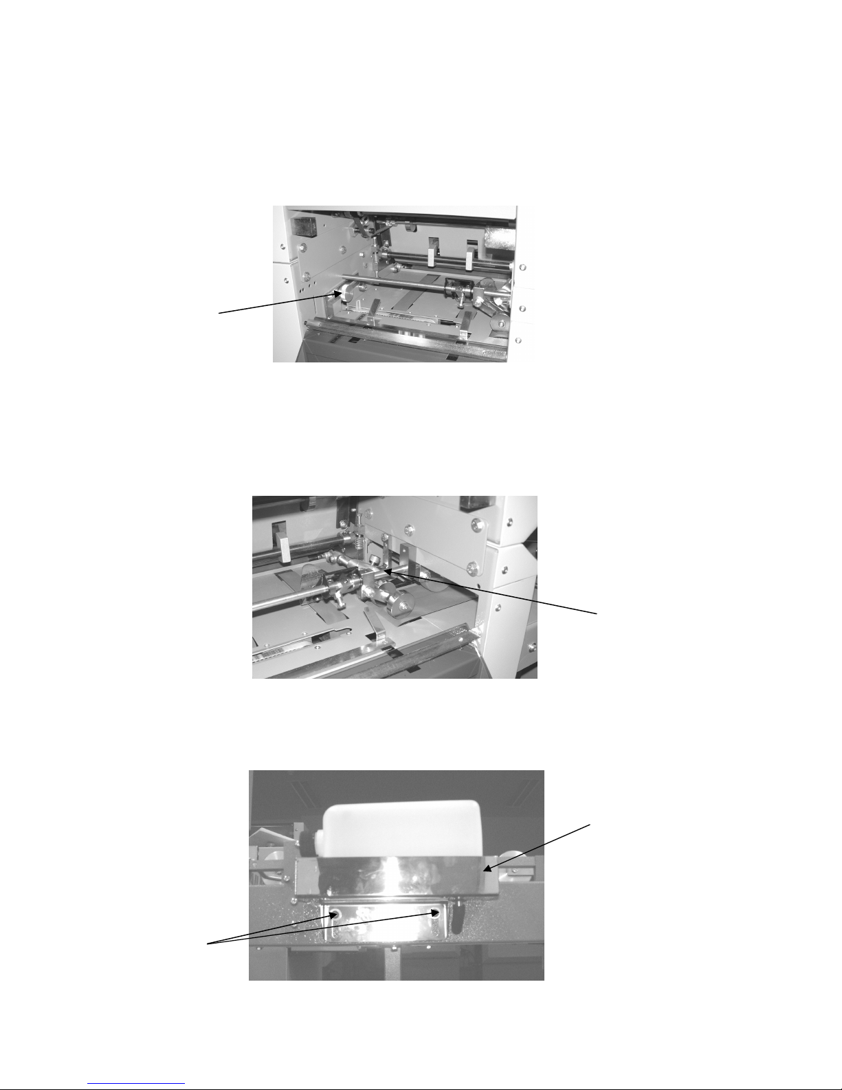
4.2.4 Wetting Brush
Adjustments can be made to the position of the brush by rotating the thumbscrew inside the
rear cover on the right hand side.
Brush
Position
Thumbscrew
To adjust the water level in the brush reservoir, the water bottle tank can be moved up or
down using the two 4mm cap head bolts. For a wetter brush move the tank up, for dryer
move it down
4mm Bolts
Water Bottle
26

4.2.5 Conveyor Stop
The conveyor stop is used to position the filled envelopes neatly onto the conveyor. Adjust
the sliding plate to the size of envelope being used with the thumbscrew on top.
Sliding
Plate
Thumbscrew
4.2.6 Feed Gates (Envelope Hopper)
Set as in section 3.1
4.2.7 Inserting Shoes
The inserting shoes act as a guide for the documents as they are pushed into the envelope. To
remove them, turn the thumbscrew anticlockwise until the shoe can be withdrawn from its
location slot. To replace, insert the shoe into the location slot, aligning the holes, and tighten
the thumbscrew.
Machine Size Shoe Size Supplied Max. Document Thickness
6 station machine 6mm and 9mm 5mm and 8mm
3 station machine 6mm 5mm
3mm shoes for thin documents are also available upon request.
Thumbscrew
Inserting Shoes
27

5. Specifications
HS565 Mailmaster
Maximum cycle speed 7200 insertions per hour
Max packing thickness Up to 8mm
Envelope type Wallet with or without window
Envelope Feeder
Envelope dimensions Minimum Maximum
Length 220mm 242mm
Depth 108mm 165mm
Flap 32mm 58mm
Throat 12mm 25mm
Recommended envelope weight 90gsm to 120gsm
Document Feeder
Minimum Maximum
Insert dimensions 160mm × 80mm 216mm × 155mm
Insert thickness 70gsm sheet 1.5mm
Book Feeder
Minimum Maximum
Insert dimensions 160mm × 80mm 216mm × 155mm
Insert thickness 70gsm sheet 5mm
It is possible that inserts not meeting these dimensions can be catered for upon request.
Electrical supply 220-240V 50Hz 1.1A (110V 60Hz 3.2A)
28

6.0 Fold examples
Top left hand address Z fold
Plate 1: Set to 200mm.
Plate 2: Set to 105mm.
Paper Feed: Top edge leading, address face up.
Top left hand address wrap fold
Plate 1: Set to 95mm.
Plate 2: Set to 105mm.
Paper Feed: Bottom edge leading, address face down.
Top left hand address V fold
Plate 1: Set to 150mm.
Plate 2: Set to deflect.
Paper Feed: Bottom edge leading, address face down.
29
 Loading...