

Kar Tech MOD190 User Manual

MOD190
MODULAR TRANSCEIVER
OEM INSTALLATION AND OPERATION MANUAL
NOTE: THIS MODULE IS LIMITED TO OEM INSTALLATION ONLY
DECEMBER 6, 2016
TH

MOD190 TRANSCEIVER
INDEX
DESCRIPTION ........................................................................... 2
OPERATION .............................................................................. 2
INSTALLATION ......................................................................... 4
BEFORE APPLYING POWER! ...................................................... 6
TROUBLESHOOTING ................................................................. 6
TRANSCEIVER PICTORIAL ........................................................ 8
SPECIFICATIONS ...................................................................... 9
INSTRUCTION TO THE USER ................................................... 10
INDUSTRY CANADA STATEMENTS ........................................... 12
1

MOD190 TRANSCEIVER
DESCRIPTION
The MOD190 is a frequency
hopping spread spectrum
transceiver module designed to
be compatible with US (FCC Part
15.247) and Canadian (RSS-247)
regulations for license free use
in the 900 MHz ISM band. The
MOD190 is designed for mobile
applications in accordance to
Part 2.1091(b).
OPERATION
The MOD190 is a radio
transceiver module for the 900
MHz ISM bands. The transceiver
microcontroller includes a CPU,
GPI/O, a fully integrated
frequency synthesizer, a power
amplifier, a modulator and a
receiver unit. The MOD190
microcontroller serial port is
connected to the host via
protection circuits. The data is
The MOD190 transceiver is only
integrated into Kar-Tech remote
control products by Kar-Tech, at
Kar-Tech. There are no user
serviceable parts on the
MOD190 transceiver.
The MOD190 is not designed for
multiple antenna applications
and should not be used to
transmit simultaneously with
any other transmitter.
sent through a serial port to RF
processor and then to RF circuit
to the antenna and the data
received from antenna is sent to
the serial port and to the host.
The microcontroller is
responsible for the control of the
entire communication. The
MOD190 transceiver contains a
DC regulator which generates a
constant 1.8 VDC for the digital
circuitry. The RF sect ion runs on
the 3.3V supply.
2

MOD190 TRANSCEIVER
The MOD190 hops on 50 channel
frequencies that are selected in
a pseudo random order. An
example of the order is:
{48, 25, 17, 20, 41, 37, 36,
10, 15, 44, 30, 6, 42, 33,
5, 8, 28, 1, 23, 49, 16, 3,
19, 29, 21, 43, 31, 9, 18,
27, 22, 45, 13, 2, 32, 11,
synchronization with the
transmitter’s signals.
14, 46, 12, 24, 4, 7, 38, 4
7, 35, 40, 50, 34, 39, 26}
where Channel 1 is 902.5 MHZ
and Channel 50 is 927.00 MHZ.
The dwell time of the hopping is
350ms. Each channel is used
equally on average.
The receivers are matched to
the transmitters to use the same
hopping channel sequence and
they hop channels in
3
MOD190 TRANSCEIVER
INSTALLATION
1) Solder the MOD190
transceiver directly to the
host’s compatible connector.
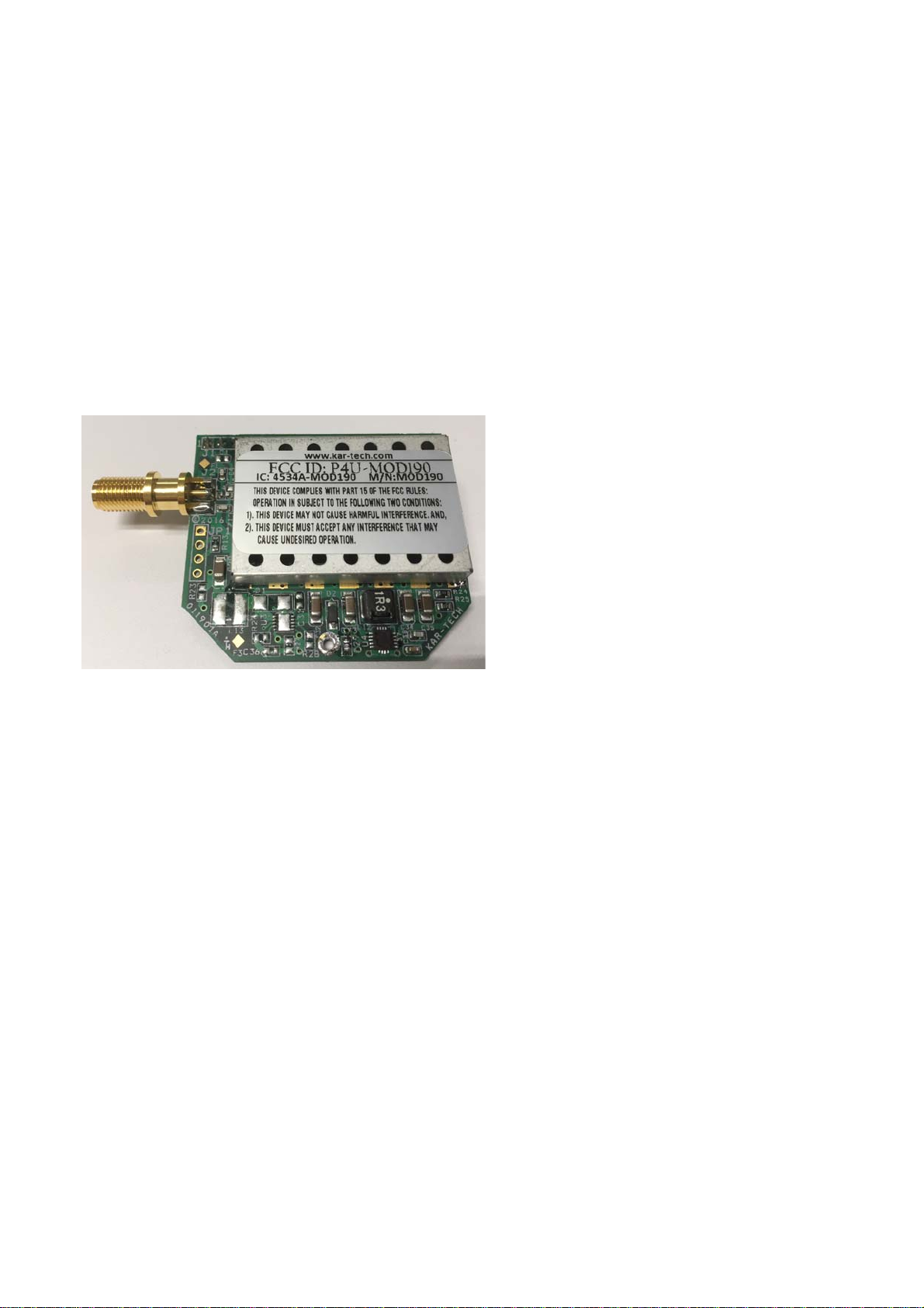
2) Print and attach the label
as shown below:
antenna.
3) Place a label on the outside
of the host enclosure in a
visible area. On the label,
include the following:
“Contains Transmitter
Module FCC ID: P4UMOD190” and “Contains
Transmitter Module IC:
4534A-MOD190”
4) Connect the appropriate
antenna. Either a ¼
wavelength wire, or a
RPSMA ¼ wavelength
4
 Loading...