

Page 1
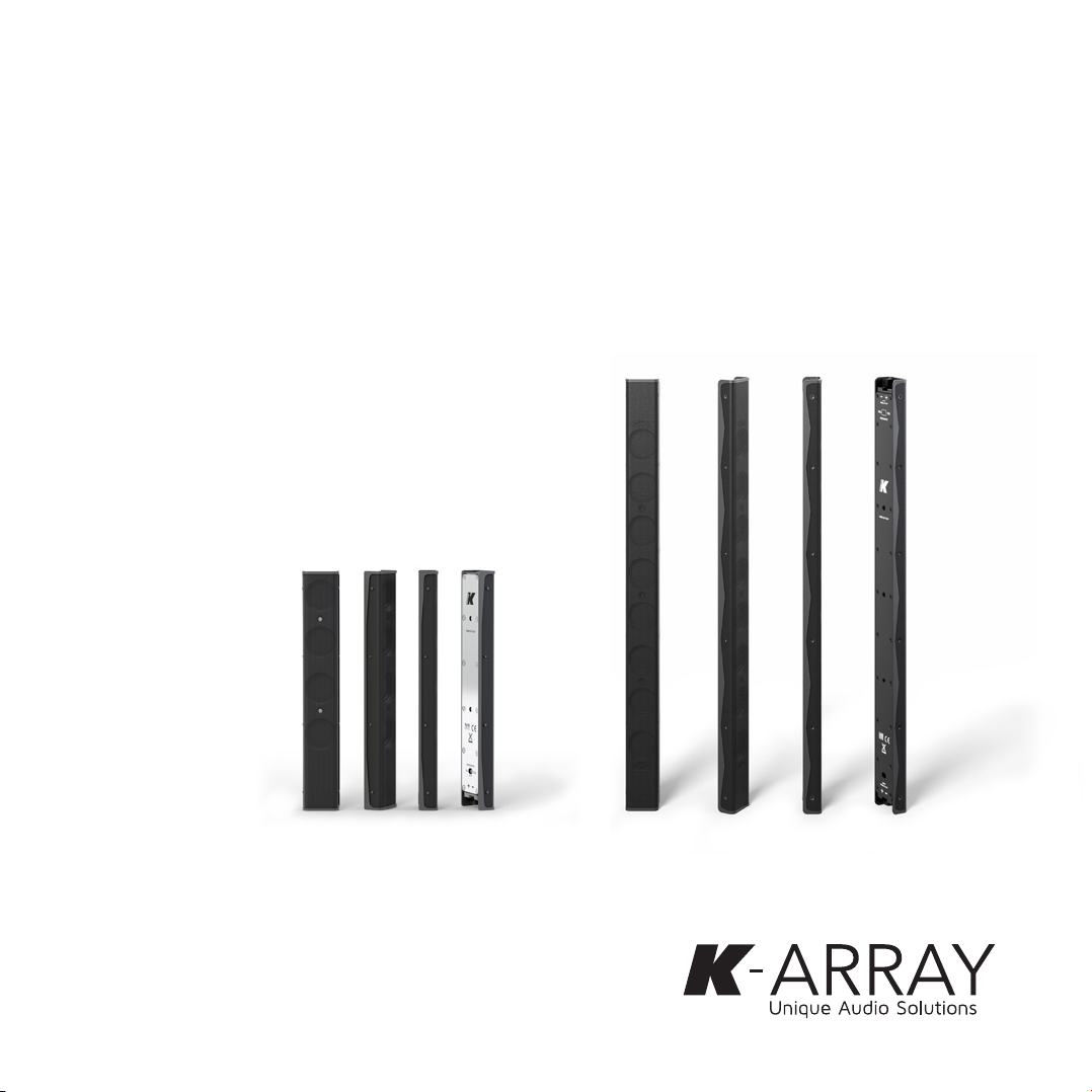
Vyper
Ultra-flat aluminum line array element
USER GUIDE
Vyper-KV52Vyper-KV25
Page 2

KV25-KV52_uguide_1.2
Page 3

Vyper
User Guide
Index
Unpacking 4
Setup 4
Quick Start Guide 5
Vyper-K V25 / Vyper-KV52 single-unit Setup 5
Multiple Vyper-K V52 Line Array Setup 5
Installation 6
Installation with Reclosable Fastener Adhesive 6
Installation with Brackets 6
Installation without Brackets 7
Joining Multiple Vyper-KV52 8
Connecting 9
Connecting Multiple Vyper-KV52 9
Impedance Settings 9
Loudspeakers in Parallel 10
Connecting the Amplifier 10
Service 11
Cleaning 11
Mechanical drawings 12
Vyper- KV25 12
Vyper- KV52 13
Technical specifications 14
1
Page 4
Vyper
User Guide
IMPORTANT SAFETY INSTRUCTIONS
Read these instructions - Keep these instructions
Heed all warnings
Warning. Failure to follow these safety instructions
could result in fire, shock or other injury or damage to
the device or other property.
Installation and commissioning may only be carried out
by qualified and authorized personnel.
Switch-off the mains power supply before carrying out
any connection or maintenance operations.
This fixture is intended for installation in accordance
with National Electric Code and local regulation:
To assure full compliance with local codes
and regulations, check with your
local electrical inspector before installation
Symbols
K-array declares that this device is in compliance
with applicable CE standards and regulations. Before
putting the device into operation, please observe the
respective country-specific regulations!
WEEE
Please dispose of this product at the end of its
operational lifetime by bringing it to your local collection
point or recycling center for such equipment.
This symbol aler ts the user to the presence of
recommendations about the product’s use and
maintenance.
The lighting flash with arrowhead symbol within an
equilateral triangle is intended to aler t the user to the
presence of uninsulated, dangerous voltage within
the product enclosure that may be of magnitude to
constitute a risk of electrical shock.
This device complies with Restriction of Hazardous
Substances Directive.
2
• Read these instructions.
• Keep this instructions.
• Heed all warnings.
• Follow all instructions.
• Do not use this apparatus near water.
• Clean only with dr y cloth.
• Do not block any ventilation openings. Install in accordance with the
manufacturer’s instructions.
• Do not install near any heat sources such as radiators, heat registers,
stoves, or other apparatus (including amplifiers) that produce heat.
• Only use attachments/accessories specified by the manufacturer.
• Use only with the cart, stand, tripod, bracket, or table
specified by the manufacturer, or sold with the apparatus.
When a cart is used, use caution when moving the car t/
apparatus combination to avoid injury from tip-over.
• Unplug this apparatus during lightning storms or when
unused for long periods of time.
• This loudspeaker system is intended for professional use.
• Beware of sound levels. Do not stay within close proximity of
loudspeakers in operation. Loudspeaker systems are capable
of producing very high sound pressure levels (SPL) which can
instantaneously lead to permanent hearing damage. Hearing damage
can also occur at moderate level with prolonged exposure to sound.
Check the applicable laws and regulations relating to maximum sound
levels and exposure times.
• Before connecting the loudspeakers to other devices, turn off the power
for all devices.
• Before turning the power on or off for all devices, set all volume levels to
minimum.
• Use only speaker cables for connecting speakers to the speaker
terminals.
• Be sure to observe the amplifier’s rated load impedance particularly
when connecting speakers in parallel. Connecting an impedance load
outside the amplifier’s rated range can damage the devices.
• Refer all servicing to qualified service personnel. Servicing is required
when the apparatus has been damaged in any way, such as powersupply cord or plug is damaged, liquid has been spilled or objects have
fallen into the apparatus, the apparatus has been exposed to rain or
moisture, does not operate normally, or has been dropped.
• K-array will not shoulder any responsibilities for products modified
without prior authorization.
• K-array cannot be held responsible for damage caused by improper use
of the loudspeakers.
General heed and warnings
Page 5

Vyper
User Guide
Thank you for choosing this K-array product!
To ensure proper operation, please carefully read this
reference manual and safety instruction before using the
product. After reading this manual, be sure to keep it for
future reference.
Should you have any questions about your new
device please contact K-array customer service at
support@k-array.com or contact the official K-array distributor
in your country.
The Vyper line is the flatest speaker in the K-array portfolio.
The passive speaker system is housed in an elegant and
resistant aluminum frame turned on a lathe from a solid
metal block.
With closely-spaced cone drivers, the Vyper line –
comprised of the half-meter-long KV52 and the 25cm-long
KV25 – demonstrates true line array characteristics: phase
coherence, low distortion and focused listening in both the
near field and at a distance from the speaker. This Pure Array
Technology allows the Vyper to cover venues uniformly and
provide long throw.
For easier use and integration with other speakers or
amplifiers, the Vypers feature selectable impedance and
when paired with a subwoofer from the Rumble or Truffle
line and powered by a Kommander amplifier with specific
presets optimized for the Vyper, the loudspeaker assures
excellent coverage of the entire musical frequency range.
3
Page 6
Vyper
User Guide
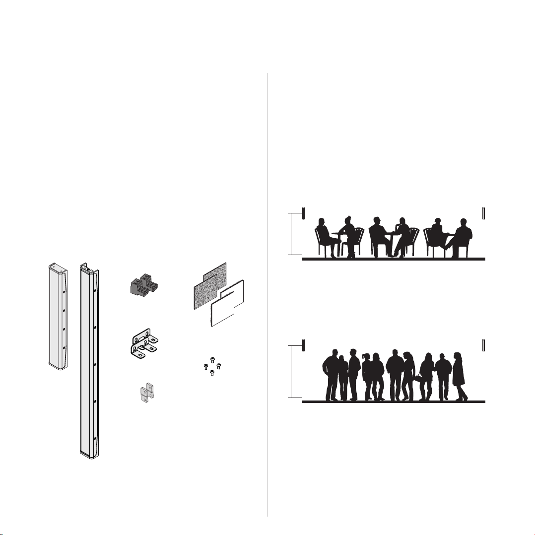
Unpacking
Each K-array product is built to the highest standard and
thoroughly inspected before leaving the factory. Upon arrival,
carefully inspect the shipping carton. If you find any damage,
immediately notify the shipping company. Check that the
following parts are supplied within the package:
A. 1x Vyper-KV25 loudspeaker
B. 2x Phoenix
MSTB 2,5/ 2-ST-5,08 BK flying
connectors
C. 4x Reclosable fastener adhesives
D. 2x Wall mount brackets
E. 4x M3x6 mm ISO7380 screws
F. 2x Joining plates
A. 1x Vyper-KV52 loudspeaker
B. 2x Phoenix
MSTB 2,5/ 2-ST-5,08 BK flying
connectors
C. 4x Reclosable fastener adhesives
D. 2x Wall mount brackets
E. 4x M3x6 mm ISO7380 screws
B
C
D
Setup
The Vyper-KV25 and the Vyper-KV52 loudspeakers perform
best when positioned on a planar surface such as a wall.
Find the proper installation height, aiming the loudspeaker at
the listening position.
We suggest the following configurations:
H
Seated listening area
H: min height 1,5 m (5 ft) / ma x height 2 m (6½ f t)
A
The accessories including in the packaging provide easy
installation in any setup: fixed or temporary.
4
F
H
E
Standing listening area
H: min height 1,7 m (5⅔ ft) / max height 2,7 m (9 ft)
Page 7

Quick Start Guide
Vyper
User Guide
Vyper-KV25 / Vyper-KV52 single-unit Setup
Follow these instructions to properly install the loudspeaker:
1. Unpack the loudspeaker and set the accessories aside
for later use;
2. Find the proper position on the mounting surface and
mark the location;
3. Set the proper cable length for connecting the
loudspeaker to the amplifier;
4. Connect the cable to the flying connector at the
loudspeaker end: see Connecting, p. 9;
5. Set the proper loudspeaker load impedance with
respect to the amplifier in use: see Impedance
Settings, p. 9;
6. Select the type of installation:
• Installation with Reclosable Fastener Adhesive, p. 6;
• Installation with Brackets, p. 6;
• Installation without Brackets, p. 7;
With respect to the type of installation selected and
the actual mounting conditions, you may be requested
to plug the flying connector to the loudspeaker before
steadily fixing the loudspeaker to the surface.
7. Once the loudspeaker is connected and affixed to
the surface, set the connection with the amplifier: see
Connecting the Amplifier, p. 10;
8. Switch on the music and enjoy!
Multiple Vyper-KV52 Line Array Setup
Follow these instructions to properly install the loudspeaker:
1. Unpack the loudspeakers and set the accessories
aside for later use;
2. Find the proper position on the mounting surface and
mark the location;
3. Set the proper cable length for connecting the first
loudspeaker of the array to the amplifier;
4. Connect the cable to the flying connector at the
loudspeaker end: see Connecting, p. 9;
5. Set the proper loudspeaker load impedance with
respect to the amplifier in use: see Impedance
Settings, p. 9;
6. Prepare the jumper wires for joining the loudspeakers
and connect the loudspeakers to each other: see
Connecting Multiple Vyper-KV52, p. 9;
7. Mechanically join the loudspeaker in line array: see
Joining Multiple Vyper-KV52, p. 8;
8. Select the type of installation:
• Installation with Reclosable Fastener Adhesive, p. 6;
• Installation with Brackets, p. 6;
• Installation without Brackets, p. 7;
With respect to the type of installation selected and
the actual mounting conditions, you may be requested
to plug the flying connector to the loudspeaker before
steadily fixing the loudspeaker to the surface.
9. Once the loudspeakers are connected and affixed to
the surface, set the connection with the amplifier: see
Connecting the Amplifier, p. 10;
10. Switch on the music and enjoy!
5
Page 8

Vyper
User Guide
Installation
Installation with Reclosable Fastener Adhesive
The reclosable fastener adhesive are intended for quick and
clean installation on flat surfaces.
Two couples of adhesives are provided, ensuring strong,
reliable and durable fastening that can be opened and closed
multiple times, for either fixed and temporary installations.
The white, acrylic, conformable foam tape bonds to a variety
of substrates, including metals and plastics.
Installation with Brackets
For permanent installation a kit including a couple of brackets
is provided. A drilling template is printed inside the packaging
box. Follow these operating instructions:
1. Cut out the drilling template from the packaging box;
2. Drill four 4 mm (0.15 in) diameter holes in the surface
following the drilling template;
4 mm
KV25
22 mm
[0.86 in]
246 m m
KV52
22 mm
[0.86 in]
4 mm
[0.16 i n]
[19.13 i n]
486 mm
[9.7 in]
[0.16 i n]
4 mm
[0.16 i n]
3. Install the loudspeaker.
2 mm Hex key
KV25
2 mm Hex key
KV52
6
Page 9
Vyper
User Guide
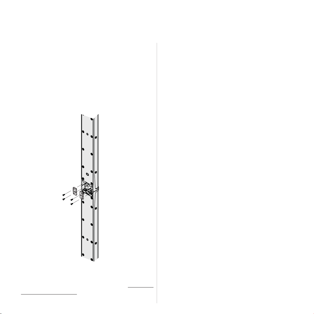
Installation without Brackets
The Vyper-KV25 and the Vyper-KV52 loudspeakers can be
eventually installed without brackets, taking advantage of the
M5 through holes hidden by the outer grill. This entitles to
use either a proper screw with 4 mm (0,16 in) max diameter,
or a M5 bolt, according to the mounting surface.
Follow the instructions for wall mounting the Vyper-KV52
loudspeaker without brackets; the procedure is the same for
the Vyper-KV25.
1. Unscrew the M3x6mm screws that tighten the grill
from the sides of the loudspeaker, using a Torx T10
screwdriver;
Tor x T10
2. Gently remove the grill from the loudspeaker;
3. Use the proper screw and plug for mounting the
loudspeaker on the surface;
4 mm max
[0.16 in max]
4. Reposition the outer grill on the loudspeaker and
tighten the screws.
7
Page 10
Vyper
User Guide
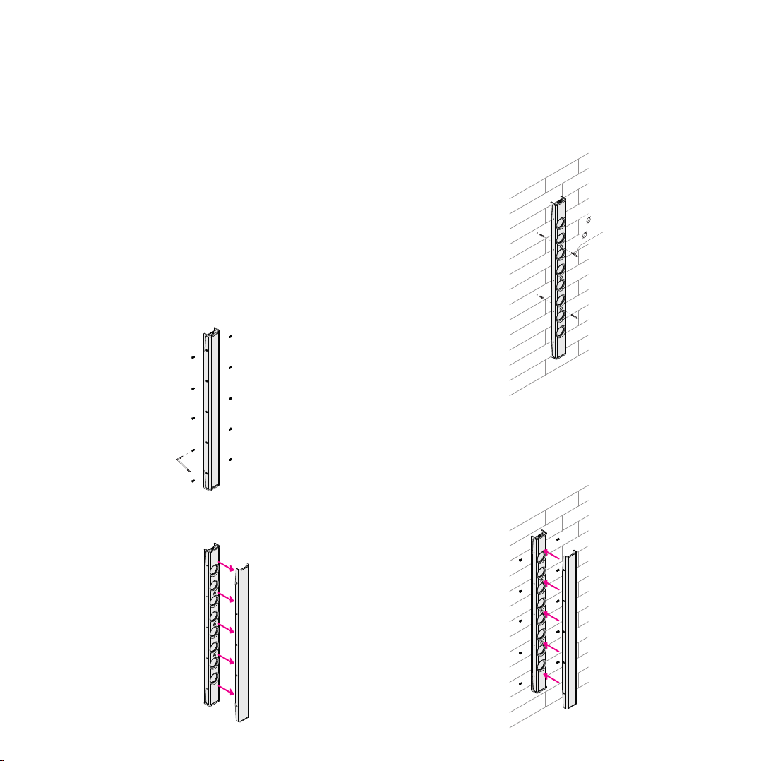
Joining Multiple Vyper-KV52
The two included joining plates allow to join two Vyper-KV52
units together to create a longer array. Use four M3x6mm
screws included in one package to join the two speakers.
The remaining M3x6mm screws from the second
loudspeaker package can be used for wall mounting the
array with a couple of brackets.
More than two units can be joined together in order to obtain
long line array.
For setting the signal routing between the arrayed
loudspeakers, please refer to the paragraph Connecting
Multiple Vyper-KV52, p. 9.
8
Page 11

Vyper
User Guide
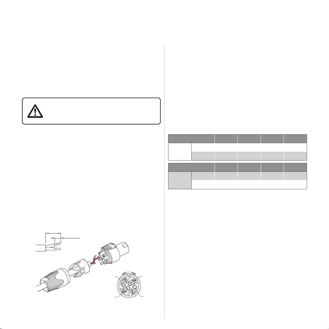
Connecting
The Vyper-KV25 and Vyper-KV52 feature euroblock 2 pin
Phoenix inlet for easy connectivity and link.
Caution must be taken when connecting the loudspeaker
cable to the flying connector to match the signal polarity:
+ HOT red wire
– COLD black/blue wire
If a label with signal polarity is not present on the flying
connector, please refer to the label on the loudspeaker
rear panel.
For a cable run of up to 5 m (16.4ft) use wire gauge of
0,75 mm2 (18 AWG) at least.
For longer cable runs a wider gauge is recommended.
12 mm (0.5 in)
6 mm (0.25 in)
Connecting Multiple Vyper-KV52
The top and the bottom connectors of the Vyper-KV52 are
paralleled so that the input signal can pass through the
loudspeaker to fed another Vyper-KV52.
A proper jumper wire must be prepared to fed the signal in
the loudspeaker joined in line array configuration (see Joining
Multiple Vyper-KV52).
Joining the loudspeakers set them in parallel (see paragraph
Loudspeakers in Parallel, p. 10).
25 mm (1 in)
6 mm (0.23 in)
Jumper wire
For the Vyper-KV52, the input signal can be fed either in the
top or in the bottom input connector.
Impedance Settings
Both the Vyper-KV25 and the Vyper-KV52 feature selectable
impedance. Selecting the proper impedance allows the
loudspeaker to match the amplifier requirements, especially
when connecting multiple loudspeakers in parallel (see
paragraph Loudspeakers in Parallel, p. 10).
A switch on the rear panel toggles the loudspeaker’s load
impedance between two values.
Vyper- KV25
Vyper- KV52
Low: 8 Ω High: 32 Ω
Low: 16 Ω High: 64 Ω
9
Page 12
Vyper
User Guide
Connecting the Amplifier
K-array’s Kommander line of amplifiers featuring built-in
DSP will operate the Vyper-KV25 and Vyper-KV52 at their
optimized performance only with the proper preset.
Load the device preset according to the connected
loudspeaker before applying any signal to the unit.
Set the dedicated Vyper-KV25 / Vyper-KV52
DEVICE PRESET on the amplifier DSP
BEFORE applying any signal to the loudspeaker
Before connecting the loudspeaker cable to the amplifier:
• ensure the loudspeaker impedance matches the
amplifier channel rated loading impedance, especially
when connecting multiple loudspeakers in parallel (see
next paragraph);
• ensure that the amplifier is switched off.
When connecting the wires to a SpeakOn NL4 connector,
screw the HOT+ wire to the terminal 1+ or 2+ and the
COLD– wire to the terminal 1- or 2-.
Loudspeakers in Parallel
By connecting the loudspeakers in parallel it is possible to
drive many loudspeakers with the same audio signal by
means of a single amplifier output channel.
The parallel connection lowers the total load impedance.
Caution must be taken to maintain the load impedance of
the paralleled loudspeakers above the amplifier’s minimum
loading impedance.
Use the table below to match the number of loudspeakers at
the specified impedance that can be connected to K-array’s
Kommander amplifiers.
KA02 KA14 KA24 KA84
Vy pe r-K V25
Vy pe r-K V52
8 Ω
32 Ω – – 8 8
16 Ω
64 Ω – – – 16
2 2 – –
KA02 KA14 KA24 KA84
– 4 4 –
25 mm (1 in)
12 mm (0.5 in)
1-
2+
10
1+
1-
1+
2+
2-
2-
Page 13

Service
To obtain service:
1. Please have the serial number(s) of the unit(s) available
for reference.
2. Contact the official K-array distributor in your country:
find the Distributors and Dealers list on K-array website.
Please describe the problem clearly and completely to
the Customer Service.
3. You will be contacted back for online servicing.
4. If the problem cannot be resolved over the phone,
you may be required to send the unit in for service. In
this instance, you will be provided with an RA (Return
Authorization) number which should be included on all
shipping documents and correspondence regarding
the repair. Shipping charges are the responsibility of the
purchaser.
Any attempt to modify or replace components of the device
will invalidate your warranty. Service must be performed by
an authorized K-array service center.
Vyper
User Guide
Cleaning
Use only a soft, dry cloth to clean the housing. Do not use
any solvents, chemicals, or cleaning solutions containing
alcohol, ammonia, or abrasives. Do not use any sprays near
the product or allow liquids to spill into any openings.
11
Page 14

260mm
Vyper
User Guide
Mechanical drawings
Vyper-KV25
M3x6 mm ISO7380
2 mm Hex key
10,2in
2,0in
52mm
3,9in
100mm
40mm
1,6in
22mm
0,8in
M5
M5
M3x6 mm
Torx T10 key
12
Page 15
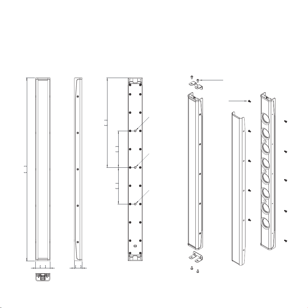
Vyper-KV52
M3x6 mm ISO7380
2 mm Hex key
M3x6 mm
Torx T10 key
Vyper
User Guide
500mm
19,7in
40mm
1,6in
22mm
0,8in
9,6in
245mm
3,9in
100mm
3,9in
100mm
M5
M5
M5
13
Page 16

Vyper
User Guide
Technical specifications
Vyper-KV25
General
Typ e Line array
Drivers 4 x 1” neodymium magnet woofers
Frequency Response 150 Hz – 18 kHz (-6 dB)
Rated Power 75 W
Maximum SPL 108 dB (peak)
Nominal Impedance 8 Ω / 32 Ω sele ctable
Crossover External crossover required
Coverage V. 25° | H. 140°
(2)
Handling & Finishes
IP Rating IP54
Dimensions (WxHxD) 40 x 260 x 22 mm (1.6 x 10.2 x 0.9 in)
Weight 0,4 kg (0.88 lb)
Colors & Finishes black, white, custom RAL, brushed and polished stainless steel, 24K gold finishes
(1)
Accessories
Recommended Amplifier Kommander-KA02, Kommander-KA14
1
With dedicated preset.
2
Maximum SPL is calculated using crest factor 4 (12dB) @ 1 m and power handling specifications, exclusive of power compression.
14
Page 17

Vyper
User Guide
Vyper-KV52
General
Typ e Line array
Drivers 8 x 1” neodymium magnet woofers
Frequency Response 150 Hz – 18 kHz (-6 dB)
Rated Power 150 W
Maximum SPL 114 dB (peak)
Nominal Impedance 16 Ω / 64 Ω selec table
Crossover External crossover required
Coverage V. 10° | H. 140°
(2)
Handling & Finishes
IP Rating IP54
Dimensions (WxHxD) 40 x 500 x 22 mm (1.6 x 19.7 x 0.9 in)
Weight 0,7 kg (1.54 lb)
Colors & Finishes black, white, custom RAL, brushed and polished stainless steel, 24K gold finishes
(1)
Accessories
Recommended Amplifier Kommander-KA02, Kommander-KA14, Kommander-KA24, Kommander-KA84
1
With dedicated preset.
2
Maximum SPL is calculated using crest factor 4 (12dB) @ 1 m and power handling specifications, exclusive of power compression.
15
Page 18

This page left intentionally blank
Page 19

Page 20

Designed and Made in Italy
K-ARRAY s u r l
Via P. Romagnoli 17 | 50038 Scarperia e San Piero - Firenze - Italy
ph +39 055 84 87 222 | info@k-array.com
www.k-array.com
 Loading...