

Page 1
KP52-KP102 Ver. 3.1
Python
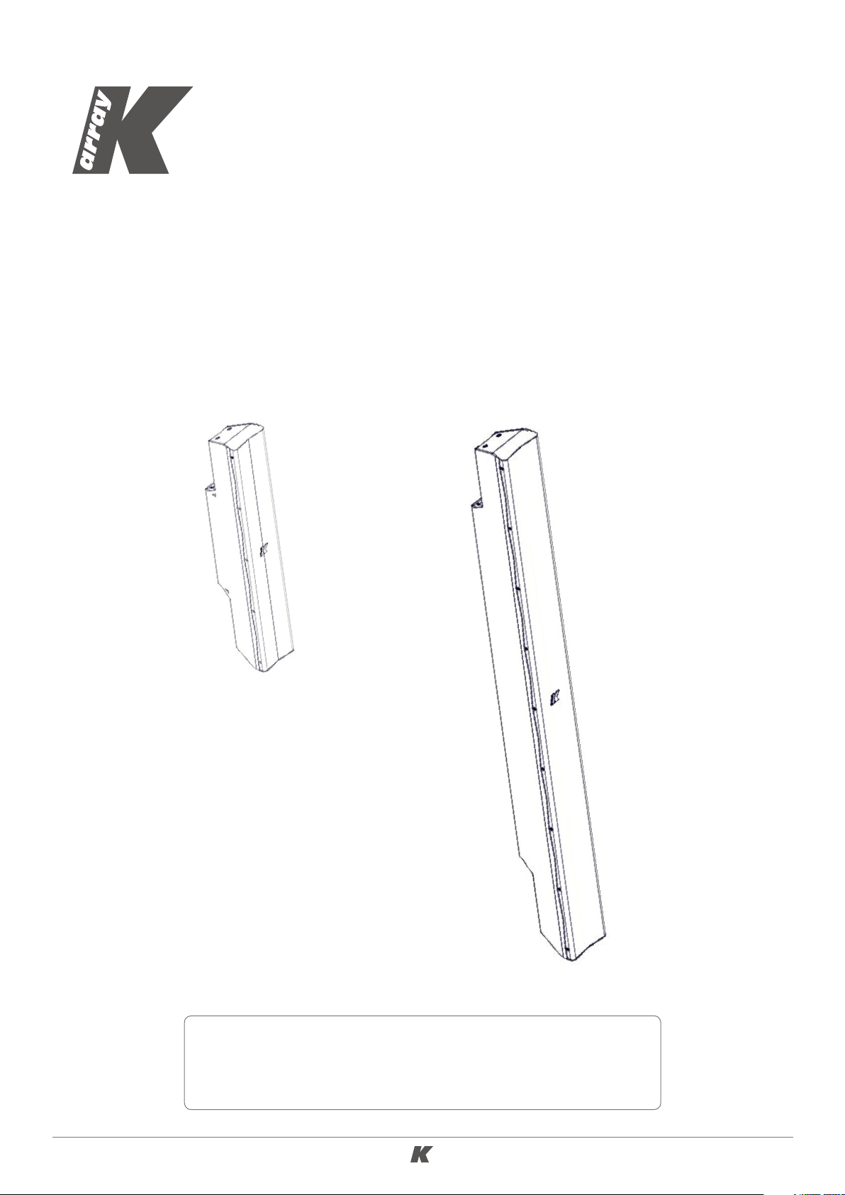
KP52 / KP52 Mark I
KP102 / KP102 Mark I
USER GUIDE
English
WHAT’S NEW IN THE MARK I VERSION?
New paint work for black and white models, no screen printing
of names and logos.
Page 2

KP52-KP102 Ver. 3.1
TABLE OF CONTENTS
SYMBOLS ................................................................................ 3
1. INTRODUCTION ..................................................................... 4
2. KEY FEATURES ...................................................................... 4
3. APPLICATIONS ....................................................................... 4
4. SAFETY INFORMATION ............................................................ 5
5. UNPACKING ......................................................................... 6
6. PHYSICAL ............................................................................. 6
6.1 KP52 L AYOUT .................................................................................... 6
6.2 KP102 LAYOUT .................................................................................. 7
7. WIRING ................................................................................ 8
7.1 IMPEDANCE SWITCH ............................................................................ 8
7.2 COVERAGE SWITCH ............................................................................. 9
8. ACCESSORIES AND CONFIGURATIONS .......................................10
8.1 SUSPENDING FROM THE FLY-BAR ...........................................................10
8.2 HANGING ON THE WALL ..................................................................... 11
8.3 STANDING ON THE BASE ..................................................................... 11
8.4 HORIZONTAL CLUSTER ........................................................................ 12
8.5 GROUND LAYING ............................................................................... 12
8.6 STANDING ON A KMT SUBWOOFER ......................................................... 13
8.7 O U T D O O R I N S TA L L ATION .................................................................... 13
9. SERVICE ............................................................................. 14
10. TECHNICAL SPECIFICATIONS .................................................. 15
11. EN54-24 DATA ..................................................................... 16
2
Page 3
KP52-KP102 Ver. 3.1
SYMBOLS
K-array declares that this device is in compliance with applicable CE
standards and regulations. Before putting the device into operation, please
observe the respective country-specific regulations!
Waste Electrical and Electronic Equipment (WEEE)
Please dispose of this product at the end of its operational lifetime by bringing
it to your local collection point or recycling center for such equipment.
This symbol alerts the user to the presence of recommendations about the
product’s use and maintenance.
Warning: DANGEROUS VOLTAGE.
Terminals marked with this symbol carry a risk of electric shock, therefore
external wiring connected to these terminals requires installation by a
qualified professional or the use of ready-made leads or cords.
This symbol alerts the user to the presence of recommendations about
product’s use and maintenance.
This device complies with the Restriction of Hazardous Substances Directive.
3
Page 4

KP52-KP102 Ver. 3.1
1. INTRODUCTION
The K-array Pythons are passive speaker systems, comprised of 3.15” neodymium magnet transducers
housed in an elegant and sturdy stainless steel chassis. Available in two lengths, the KP52 features 6
drivers in a 0.5 m (20”) chassis, while the KP102 features 12 drivers in a 1 m (40”) chassis.
The Pythons’s closely spaced cone drivers provide phase coherence, low distortion and focused listening
both up close and at a distance.
To accommodate a range of applications, the vertical dispersion pattern can be switched for either wide
or narrow coverage.
Optional rigging and linking accessories allow multiple speakers to be interconnected, creating a wide
array of vertical and horizontal configurations for temporary or permanent installation.
For integration with other speakers or amplifiers, the KP52 and KP102 offer selectable impedance
(8Ω /32Ω for the KP52 and 4Ω/16Ω for the KP102).
Pythons are able to reproduce the entire vocal frequency range with excellent intelligibility, starting from
120 Hz.
Integrating powered K-array subwoofers (KMT12, KMT18, KMT21, KMT218) ensures excellent coverage of
the entire musical frequency range. K-array’s KA amplifier series also features custom presets, optimized
for use with the Python series.
All Python components are designed by K-array and custom-made under K-array’s quality control system.
2. KEY FEATURES
• Unique performance-to-size ratio
• Vertical, Horizontal and 3D line-array applications
• Multiple 3.15” long-excursion full-range cone drivers
• Wide horizontal coverage
• Selectable vertical pattern (Spot/Flood)
• Electronically protected
• Selectable impedance (KP52: 8/32 Ω, KP102: 4/16 Ω)
• Weather proof, suitable for outdoor installations - IP54
3. APPLICATIONS
• Theatre, club, house of worship
• Front fill and under-balcony fill
• Portable and installed AV systems
• Stage and AV studio monitoring
4
Page 5

KP52-KP102 Ver. 3.1
4. SAFETY INFORMATION
Warning: failure to follow these safety instructions could result in injury
or damage to the device or other property.
IMPORTANT SAFETY INSTRUCTIONS
• Read these instructions.
• Keep this instructions.
• Heed all warnings.
• Follow all instructions and keep all warnings.
• Only use attachments/accessories specified by the manufacturer.
• Use only with the cart, stand, tripod, bracket, or table specified by the manufacturer or
sold with the apparatus.
• When a cart is used, use caution when moving the cart/apparatus combination to avoid
injury from tip-over.
• Avoiding hearing damage. Professional loudspeakers are capable of producing extremely high sound
levels and should be used carefully. Never stand close to loudspeakers driven at high volume. Set
the volume to a safe level. You can adapt over time to a higher volume of sound that over time
may sound normal but can be damaging to your hearing. Hearing loss worsens after exposure to a
sound level of 90 dB or over for an extended period of time. If you experience ringing in your ears
or muffled speech, stop listening and have your hearing checked. The louder the volume, the less
time is required before your hearing could be affected.
• Choking Hazards. This device contains small parts, which may present a choking hazard to small
children. Keep the device and its accessories away from small children.
• Do not make repairs yourself. Never attempt to disassemble, repair or modify the system yourself.
Disassembling the unit may cause damage that is not covered under the warranty. The device contains
no user-serviceable parts. Repairs should only be performed by factory trained service personnel.
• Sound distortion. Do not operate speakers for an extended period of time with sound distortion. This
is an indication of malfunction, which in turn can generate heat and result in a fire.
• Carrying, handling and installing the device. The device contains sensitive components. Do not drop,
disassemble, open, crush, bend, deform, puncture, shred, incinerate, paint, or insert foreign objects
into it. If your device has been dropped or damaged unplug the power cable immediately.
• Set up. Set up your device on a stable retaining horizontal surface. If combined or mechanically
connected with other products, always verify the stability of the resulted system. Install the unit only
in a location that can structurally support the weight of the unit and far away from people who can
interfere with the stability of the system. Assure that the wind does not interfere with the system’s
stability, taking extra securities like chains, weights, ropes or any other certified anchoring systems.
Doing otherwise may result in the unit falling down, causing personal injury or property damage
or even death. The system should only be suspended by qualified personnel following safe rigging
practices. Secure fixings to the building structure are vital. To clarify any doubt you may have, seek
help from architects, structural engineers or other specialists.
5
Page 6

KP52-KP102 Ver. 3.1
5,9in
150mm
8,7in
220mm
5,9in
150mm
3,5in
88,5mm
5,0in
127mm
4,6in
118mm
0,8in
21mm
4,8in
121,8mm
0,8in
21mm
5. UNPACKING
Each K-array speaker is built to the highest standard and thoroughly inspected before leaving the
factory. Upon arrival, carefully inspect the shipping carton, then examine and test your new amplifier.
If you find any damage, immediately notify the shipping company. Only the consignee may institute a
claim procedure regarding the system’s electronic equipment.
6. PHYSICAL
6.1 KP52 L AYOUT
5.8 kg (12.8 lbs)
Weight
6
Page 7

KP52-KP102 Ver. 3.1
ni0,5
mm821
6.2 KP102 LAYOUT
5,9in
150mm
1,1in
27,5mm
4,8in
121,8mm
27,6in
700mm
1,1in
27,5mm
150mm
5,9in
4,6
118mm
3,5in
88,5mm
39,4in
1000mm
Weight
12 kg (26.5 lbs)
7
Page 8

KP52-KP102 Ver. 3.1
7. WIRING
KP52 and KP102 internal wiring is designed to pick up audio power signal from pins 1+ / 1- of a Speakon
NL4 connector. Pins 1+ and 1-, such as pins 2+ and 2-, are directly wired from one socket to the other,
so the two sockets are equivalent and can be used to connect the speaker to the amplifier or to connect
the speaker to another one driven in parallel by the same amplifier channel.
IMPEDANCE SWITCH COVERAGE SWITCH
7.1 IMPEDANCE SWITCH
KP52 and KP102 features a switch which allows users to select the impedance of the speaker
(KP52: 8/32 Ω, KP102: 4/16 Ω).
The value to be selected depends mainly on the amplifier you use to drive the unit. Impedance must
be set to high (32 Ω for KP52 and 16 Ω for KP102) when speakers are driven by KMT active modules
or by the KA84 amplifier. Low impedance may be used when speakers are driven by a KA24 amplifier.
Please refer to your amplifier’s specifications to select the correct speaker impedance for your
configuration.
KA24 amp KA84 amp KMT sub
KP52 @ 8 Ω
YES
NO
KP52 @ 32 Ω NO YES
NO
YES
KP102 @ 4 Ω YES NO NO
KP102 @ 16 Ω NO YES YES
8
Page 9

KP52-KP102 Ver. 3.1
7.2 COVERAGE SWITCH
KP52 and KP102 feature a switch which allows users to select the vertical coverage of the speaker.
Flood coverage sets a wide vertical diffusion. Flood coverage is suggested for single speakers in diffused
short throw applications to obtain maximum diffusion with a minimum footprint.
Spot coverage sets a narrower vertical diffusion angle and is recommended for long throw or monitoring
application.
When more units are combined in a line array configuration, make sure to set the coverage to Spot.
SPOT Coverage
FLOOD Coverage
9
Page 10

KP52-KP102 Ver. 3.1
8. ACCESSORIES AND CONFIGURATIONS
K-array offers a variety of dedicated accessories to mount and interconnect the speakers for a wide
range of applications.
In this section we introduce you to the main accessories available for this product.
8.1 SUSPENDING FROM THE FLY-BAR
KP52 and KP102 units can be suspended using the K-FLY2 fly bar accessory and the K-JOINT2 hardware
accessory used to connect together two units or to connect a unit to the fly bar. Mixed configuration
with both KP52s and KP102s in the same cluster are also possible.
Consult the dedicated K-FLY2 User Guide for safety
information and operation details.
10
Page 11

KP52-KP102 Ver. 3.1
8.2 HANGING ON THE WALL
The K-WALL2 and K-WALL2L accessories are used to mount a speaker on a wall.
In case of outdoor installation, we recommend to
not remove the protection plate that covers the
switches. Use the screws included in the K-WALL2
and K-WALL2L to fix the bracket to the speaker
keeping the switches protected by the plate.
K-WA L L 2 K-WA L L 2L
8.3 STANDING ON THE BASE
The K-BASE2 accessory assists in standing up to 2 meters of KP52/KP102. For proper installation and
operation, connect the units to the base with K-FOOT2 and K-JOINT2 accessories. Where possible,
screw the feet of the K-BASE2 to the ground.
11
Page 12

KP52-KP102 Ver. 3.1
8.4 HORIZONTAL CLUSTER
The KP-CLUSTER2 accessory is used to mount on a horizontal cluster of three KP52/KP102 speakers
on the wall.
KP-CLUSTER2 comes in a set of three different models: one with no angle between the three speakers,
one with a 30° angle between the speakers, one with a 60° angle between the speakers.
8.5 GROUND LAYING
KP-STAGE allows users to safely lay the speakers on the ground with three different angles: 0°, 30° and
45°. Ideal applications are monitoring and front-fill.
12
Page 13

KP52-KP102 Ver. 3.1
8.6 STANDING ON A KMT SUBWOOFER
Up to two meters of KP52/KP102 can be mounted on a KMT subwoofer by using the K-FOOT2 and
K-JOINT2 accessories.
Acoustically speaking, two KP102s perfectly match with a KMT21 subwoofer. An excellent example of
the use of this combination is the K-array portable system KR402.
KMT21 + 2 x KP102
8.7 O U T D O O R I N S TA L L ATION
In case of outdoor installation, use the K-IP65KITA weatherproof cap (not included) to close not connected
NL4 sockets. Use the K-IP65KITB weatherproof rubber cable cover (not included) to further protect
wired NL4 connectors. We also recommend to not remove the protection plate that covers the switches.
Included seal goes here
Included seal goes here
K-IP 65 K ITA K-IP65KITB
13
Page 14

KP52-KP102 Ver. 3.1
9. SERVICE
To obtain service:
1) Contact the official K-array distributor in your country. Your local distributor will direct you to the
appropriate service center.
2) If you are calling for service, please have the serial number(s) of the unit(s) available for reference.
Ask for Customer Service and be prepared to describe the problem clearly and completely.
3) If the problem cannot be resolved over the phone, you may be required to send the unit in for
service. In this instance, you will be provided with an RA (Return Authorization) number which should
be included on all shipping documents and correspondence regarding the repair. Shipping charges are
the responsibility of the purchaser.
Any attempt to modify or replace components of the device will invalidate your warranty. Service must
be performed by an authorized K-array service center.
Cleaning:
Use only a soft, dry cloth to clean the product. Do not use any solvents, chemicals, or cleaning
solutions containing alcohol, ammonia, or abrasives. Do not use any sprays near the product or
allow liquids to spill into any openings.
14
Page 15

KP52-KP102 Ver. 3.1
10. TECHNICAL SPECIFICATIONS
KP52 KP102
ACOUSTICS
Rated Power 360 W
Frequency Range 120 Hz – 18 kHz (- 10dB)
Impedance 8 Ω / 32 Ω (selectable)
Maximum SPL 128 dB (peak)
(2)
COVERAGE
Horizontal
Vertical
90°
10°- 45° (selectable)
CROSSOVER
Typ e External Crossover required
Frequency
120 Hz, 24 dB/oct
suggested minimum
TRANSDUCERS
Full range
6 x 3.15” Neodymium magnet with 1”
voice coil
SELECTION SWITCHES
Impedance
8 Ω / 32 Ω
Coverage Spot / Flood
POWER AUDIO INPUT/LINK
Connector 2 x 4-pin Speakon
Wiring 1+ 1- (signal IN & LINK); 2+ 2- (through)
RECOMMENDED AMPLIFIERS
Typ e KA24, KA8 4, KMT
CERTIFICATION
IP 54
PHYSICAL
Dimensions
89 x 520 x 118 mm
(3.5 x 20.5 x 4.7 in)
Weight 5.8 kg (12.78 lbs)
ACOUSTICS
Rated Power 720 W
(1)
Frequency Range 120 Hz – 18 kHz (- 10dB)
(1)
Impedance 4 Ω / 16 Ω (selectable)
Maximum SPL 134 dB (peak)
(2)
COVERAGE
Horizontal
Vertical
90°
7°- 30° (selectable)
CROSSOVER
Typ e External Crossover required
Frequency
120 Hz, 24 dB/oct
suggested minimum
TRANSDUCERS
Full range
12 x 3.15” Neodymium magnet with 1”
voice coil
SELECTION SWITCHES
Impedance
4 Ω / 16 Ω
Coverage Spot / Flood
POWER AUDIO INPUT/LINK
Connector 2 x 4-pin Speakon
Wiring 1+ 1- (signal IN & LINK); 2+ 2- (through)
RECOMMENDED AMPLIFIERS
Typ e KA24, KA8 4, KMT
CERTIFICATION
IP 54
PHYSICAL
Dimensions
89 x 1000 x 118 mm
(3.5” x 39.4 x 4.7 in)
Weight 12.0 kg (26.5 lbs)
Notes fo r data
1. With dedic ated prese t;
2. Maximum SPL i s calculated using crest f actor 4 (12dB) f rom sensi tivity sc aled @1m and power handling specif ications , exclusive of powe r compression.
New material s and design are introduced into existing produc ts withou t previous no tice. Prese nt systems may differ in some respe cts fr om those presented in this
catalo gue.
15
Page 16

KP52-KP102 Ver. 3.1
11. EN54-24 DATA
KP52 I and KP102 I are EN54-24 compliant. Consider the specifications below when either model is
used in a voice alarm system.
KP52 I KP102 I
Power handling 15 W
SPL 1W/1m 96
Maximum SPL 107 dB
Connector IN 1+ 1-
Vmax In (Pink Noise)
Frequency Range 100 Hz - 20 kHz
Coverage Horizontal
Coverage Vertcal
8.20 V @ 8 Ohm
16.40 V @ 32 Ohm
180° @ 500 Hz
170° @ 1000 Hz
130° @ 2000 Hz
120° @ 4000 Hz
50° @ 500 Hz
25° @ 1000 Hz
12° @ 2000 Hz
20° @ 4000 Hz
Power handling 15 W
SPL 1W/1m 99
Maximum SPL 110 dB
Connector IN 1+ 1-
Vmax In (Pink Noise)
Frequency Range 100 Hz - 20 kHz
Coverage Horizontal
Coverage Vertcal
5.80 V @ 4 Ohm
11.60 V @ 16 Ohm
180° @ 500 Hz
170° @ 1000 Hz
130° @ 2000 Hz
120° @ 4000 Hz
20° @ 500 Hz
12° @ 1000 Hz
7° @ 2000 Hz
10° @ 4000 Hz
K-array
0068-CPR-xxx /2017
EN 54-24 : 2008
Loudspeaker for voice alrm systems for fire
detection and fire alarms systems for buildings
KP52 I
TYPE B
The contents of this manual are furnished for informational purposes only. K-array s.u.r.l. assumes no responsibility for any errors or inaccuracies that may
appear in this manual. K-array s.u.r.l. reserves the right to make modifications without prior notice.
Loudspeaker for voice alrm systems for fire
detection and fire alarms systems for buildings
K-array
0068-CPR-xxx /2017
EN 54-24 : 2008
KP102 I
TYPE B
16
 Loading...