

Page 1
KR PORTABLE SYSTEM Ver. 1.0
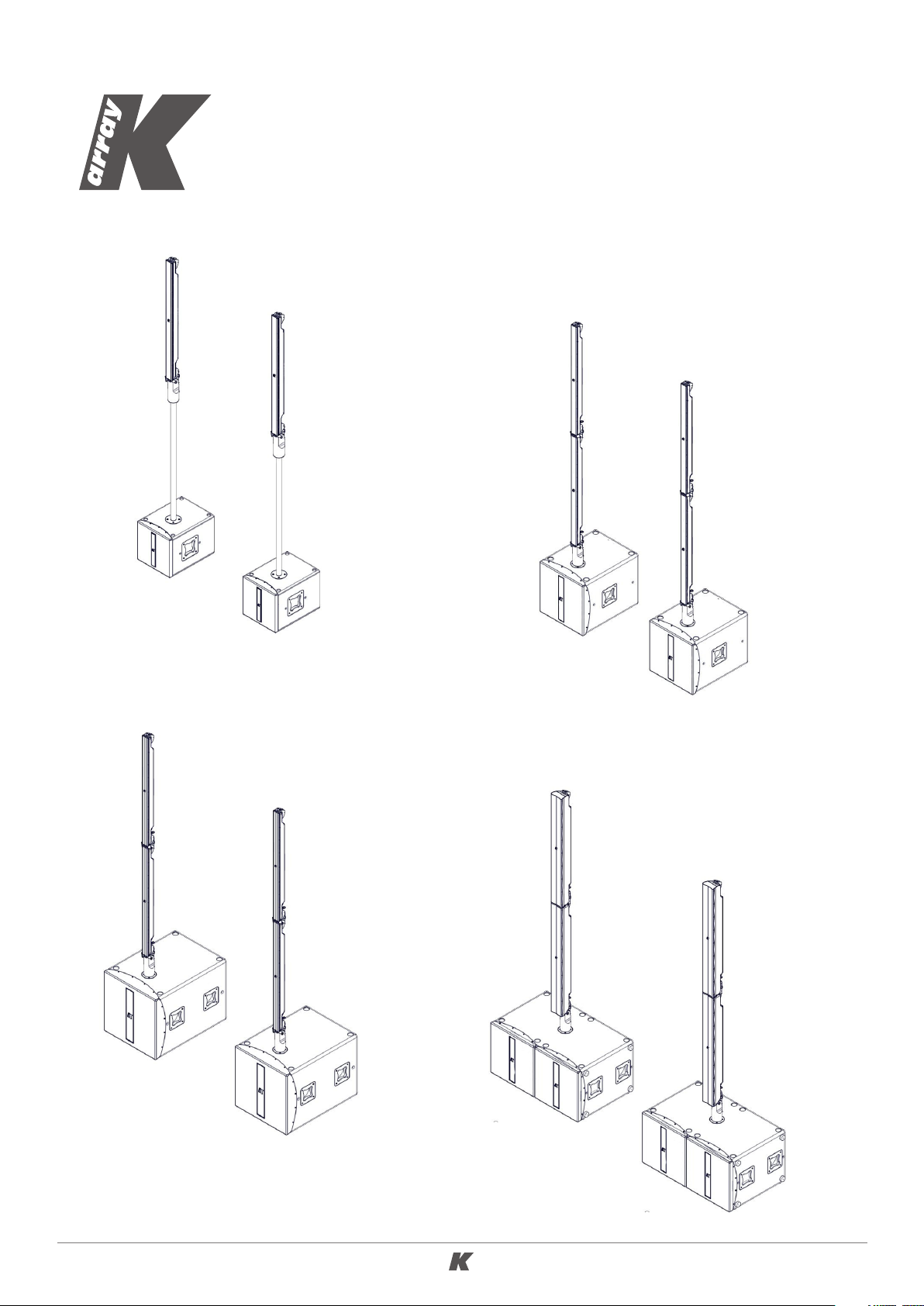
KR102 / KR102 I
KR202 / KR202 I
KR402 / KR402 I
KR802
USER GUIDE
English
KR102 / KR102 I
KR202 / KR202 I
KR402 / KR402 I
KR802
Page 2

KR PORTABLE SYSTEM Ver. 1.0
TABLE OF CONTENTS
1. INTRODUCTION ..................................................................... 3
2. KEY FEATURES ...................................................................... 3
3. APPLICATIONS ....................................................................... 3
4. SAFETY INFORMATION ............................................................ 4
5. UNPACKING ......................................................................... 6
6. SYSTEM COMPONENTS ........................................................... 7
6.1 K R102 .............................................................................................. 7
6.2 KR202 ............................................................................................. 9
6.3 KR402 ............................................................................................ 11
6.4 KR802 ............................................................................................ 13
7. SYSTEM SETUP ..................................................................... 15
7.1 KR102 SETUP .................................................................................... 15
7.2 KR202, KR402, KR802 SETUP ............................................................... 19
8. AMPLIFIER .......................................................................... 24
8.1 AC POWER ...................................................................................... 24
8.2 VOLTAGE REQUIREMENTS ................................................................... 24
8.3 CURRENT REQUIREMENTS ................................................................... 24
8.4 PROTECTION CIRCUITRY ..................................................................... 25
8.5 REAR PANEL SETTINGS: KMT12 I, KMT18 I, KMT21 I .................................... 26
8.6 REAR PANEL SETTINGS: KMT12, KMT18, KMT21 ......................................... 28
8.7 RS485 NETWORK ............................................................................. 30
9. TOUCH SCREEN FUNCTIONS ................................................... 31
9.1 TOUCH SCREEN FUNCTIONS: KMT12 I, KMT18 I, KMT21 I, KMT218 .................... 31
9.2 TOUCH SCREEN FUNCTIONS: KMT12, KMT18, KMT21 ................................... 34
9. SERVICE ............................................................................ 36
2
Page 3

KR PORTABLE SYSTEM Ver. 1.0
1. INTRODUCTION
The KR systems are integrated, self-powered speaker systems featuring mid-high line array elements
matched to powered subwoofers. All systems feature two channels of Class D amplification housed in
the subwoofer(s). The rear panel provides input for 2 balanced line signals and a digital signal in AES/
EBU protocol. And with the K-dante accessory, the system can be used in a Dante network.
An integrated touch screen provides intuitive managing and editing of powerful DSP controlling: input
and output levels, In/Out routing, subwoofer delay up to 12 ms, Speakon output to the mid-high element
with delay of up to 12 ms, and overall system delay up to 330 ms. All DSP functions, including EQ can
be controlled with remote managing software via USB or RS485, again, conveniently on a standard XLR.
The Mark I version is the newest version of the KR102, KR202 and KR402 systems, featuring new auto
range amplifiers, new codecs that reduce the signal/noise ratio, a 5v dc power connector on the rear
amplifier panel and enhanced functionality for creating presets. The output AES/EBU is now latency-free
(through) and other updates include a larger LCD screen (2.8”), the removal of the e-fun connector and
a new paint job for the mid-high elements. All these features are included in the KR802 as well.
All KR systems are designed by the K-array R&D department and custom made under the K-array quality
control system.
2. KEY FEATURES 3. APPLICATIONS
• Unique performance-to-size ratio
• Line array emission wavefront
• Onboard DSP with dedicated presets
• Ultra-fast setup and dismantling system
• Analog and digital AES-EBU inputs
• RS485 and USB connectivity for remote
control
• Concert halls
• Theatrical sound reinforcement
• Houses of worship
• A/ V systems
• Cinema and special effects
3
Page 4
KR PORTABLE SYSTEM Ver. 1.0
4. SAFETY INFORMATION
Read these instructions - Keep these instructions - Heed all warnings
Warning: Failure to follow these safety instructions could result in fire,
shock or other injury or damage to the device or other property.
The lighting flash with arrowhead symbol within
This symbol alerts the user to the presence of
recommendations about the product’s use and
maintenance.
an equilateral triangle is intended to alert the
user to the presence of not isolated, dangerous
voltage within the product enclosure that may
be of magnitude to constitute a risk of electrical
shock.
IMPORTANT SAFETY INSTRUCTIONS
• Follow all instructions.
• Do not use this apparatus near water.
• Clean only with dry cloth.
• Do not block any ventilation openings. Install in accordance with the manufacturer’s instructions.
• Do not install near any heat sources such as radiators, heat registers, stoves, or other apparatus
(including amplifiers) that produce heat.
• Do not defeat the safety purpose of the polarized or grounding-type plug. A polarized plug has two
blades with one wider than the other. A grounding type plug has two blades and a third grounding
prong. The wide blade or the third prong are provided for your safety. If the provided plug does not
fit into your outlet, consult an electrician for replacement of the obsolete outlet.
• Protect the power cord from being walked on or pinched particularly at plugs, convenience receptacles,
and the point where they exit from the apparatus.
• Only use attachments/accessories specified by the manufacturer.
• Use only with the cart, stand, tripod, bracket, or table specified by the manufacturer, or sold with
the apparatus.
• When a cart is used, use caution when moving the cart/apparatus combination to avoid injury from
tip-over.
• Unplug this apparatus during lightning storms or when unused for long periods of time.
• Refer all servicing to qualified service personnel. Servicing is required when the apparatus
has been damaged in any way, such as power-supply cord or plug is damaged, liquid has
been spilled or objects have fallen into the apparatus, the apparatus has been exposed to rain or
moisture, does not operate normally, or has been dropped.
4
Page 5
KR PORTABLE SYSTEM Ver. 1.0
WARNING
• Since the device is a CLASS I apparatus, it must be only connected to an AC three-wire grounding outlet.
If your outlet isn’t grounded, contact a licensed electrician to replace it with a property grounded
outlet.
• To reduce the risk of electric shock, unplug the AC mains connector before installing audio cable.
Reconnect the power cord only after making all signal connections. Do not use the product if the
power cord is broken or frayed. Protect the power cord from being walked upon or pinched.
• To completely disconnect this apparatus from the AC mains, disconnect the power supply cord plug
from the AC receptacle.
• Avoiding hearing damage. Professional loudspeakers are capable of producing extremely high sound
levels and should be used carefully. Never stand close to loudspeakers driven at high volume. Set
the volume to a safe level. You can adapt over time to a higher volume of sound that may sound
normal but can be damaging to your hearing. Hearing loss get worse every time you’re exposed to a
sound level of 90 dB or over for an extended period of time. If you experience ringing in your ears
or muffled speech, stop listening and have your hearing checked. The louder the volume, the less
time is required before your hearing could be affected.
• Voltage requirement. Make sure that the supplied voltage stays within the specified range. Verify that
your mains connection satisfies the power ratings of the device.
• Only connect the power supply to an appropriate power outlet
• Do not install the amplifier in wet or humid locations without using weather protection.
• TO REDUCE THE RISK OF FIRE OR ELECTRIC SHOCK, do not expose this apparatus to rain or moisture
and objects filled with liquids, such as vases, should not be placed on this apparatus.
• The main plug of the power supply cord shall remain readily accessible.
CAUTION
• Choking Hazards. This device contains small parts, which may present a choking hazard to small
children. Keep the device and its accessories away from small children.
• It is important that loudspeaker systems are used in a safe manner.
• Do not make repairs yourself. Caution, risk of electric shock. Do not open the device, it contains
potentially hazardous voltage. Never attempt to disassemble, repair or modify the system yourself.
Disassembling the unit may cause damage that is not covered under the warranty. The device
contains no user-serviceable parts. Repairs should only be performed by factory trained service
personnel. Do not plug the power cord in if you suspect that your device needs service or repair.
• Sound distortion. Do not operate speakers for an extended period of time with sound distortion. This
is an indication of malfunction, which in turn can generate heat and result in a fire.
• Cooling. During the use, it is normal for the device to get warm. The exterior of the device functions
as a cooling surface that transfers heat from inside the unit to the cooler air outside. The device
should be placed so that its location does not interfere with its proper cooling. For example, the
device shouldn’t be placed next to surfaces that can interfere with the properly cooling of the rear
panel’s radiators. When operating, the device should not be cover with additional protections.
5
Page 6

KR PORTABLE SYSTEM Ver. 1.0
• Temperature. Operate the device in a place where the temperature is between -20°C and 35°C (-4°F
to 95° F). Avoid dramatic changes in temperature or humidity when using it, as condensation may
form on or within the device.
• Take care not to spill any food or liquid through the device’s grill. Do not attempt to dry the device
with an external heat source, such as a hair dryer.
• Carrying, handling and installing the device. The device contains sensitive components. Do not drop,
disassemble, open, crush, bend, deform, puncture, shred, incinerate, paint, or insert foreign objects
into it. If your device has been dropped or damaged unplug the power cable immediately.
• Set up. Set up your device on a stable retaining horizontal surface. If combined or mechanically
connected with other products, always verify the stability of the resulted system. Install the unit
only in a location that can structurally support the weight of the unit, far away from people who
can interfere with the stability of the system. In case of outdoor installation, protect the device from
rain and moisture. Assure that the wind does not interfere with the system’s stability, taking extra
securities like chains, weights, ropes or any other certified anchoring systems. Doing otherwise may
result in the unit falling down, causing personal injury or property damage or even death. The system
should only be suspended by qualified personnel following safe rigging practices. Secure fixings
to the building structure are vital. To clarify any doubt you may have, seek help from architects,
structural engineers or other specialists.
• This audio system is not intended for use in the operation of nuclear facilities, aircraft navigation
or communication systems, air traffic control systems,or for any other uses where the failure of the
audio system could lead to death, personal injury, or sever environmental damage.
5. UNPACKING
Each K-array speaker is built to the highest standard and thoroughly inspected before leaving the
factory. Upon arrival, carefully inspect the shipping carton, then examine and test your new amplifier.
If you find any damage, immediately notify the shipping company. Only the consignee may institute a
claim procedure regarding the system’s electronic equipment.
6
Page 7
KR PORTABLE SYSTEM Ver. 1.0
6. SYSTEM COMPONENTS
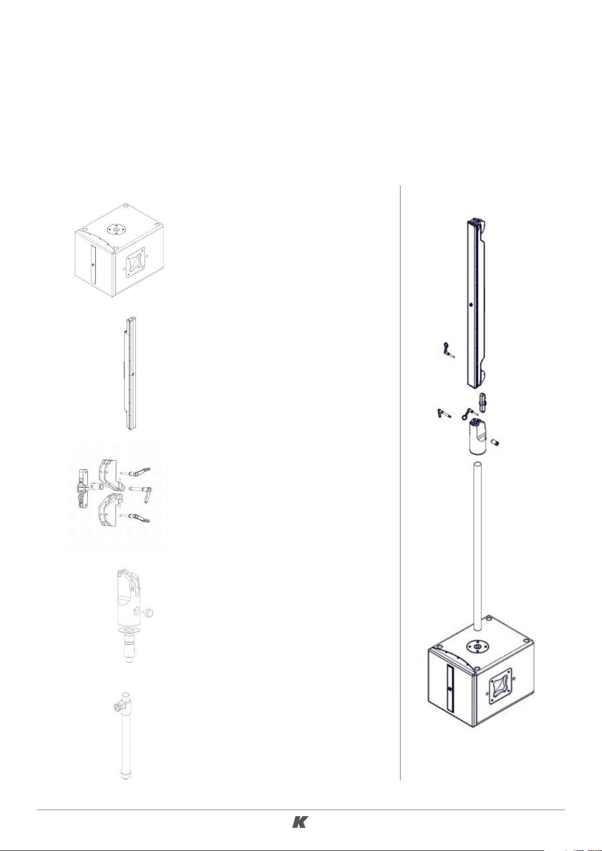
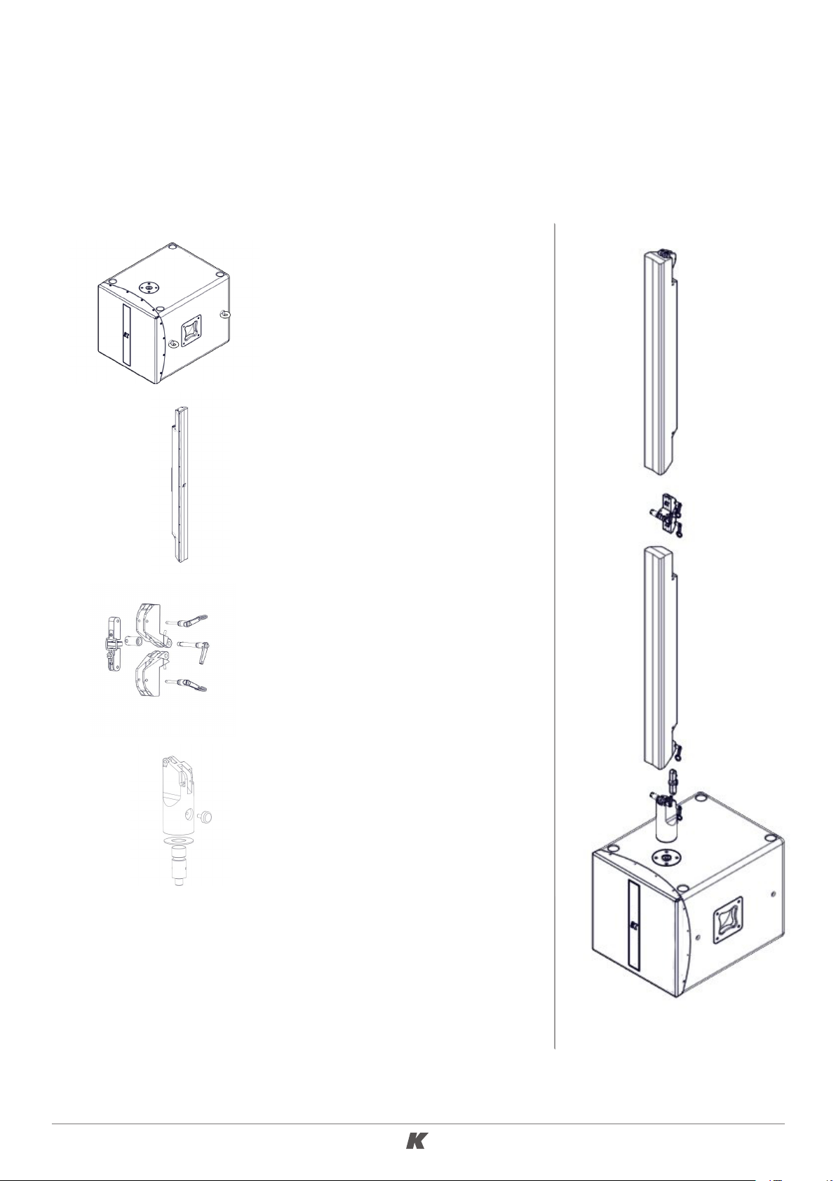
6.1 K R102
The KR102 is composed of 2 x KMT12 12’’ subwoofers + 2 x KK102K plastic cases with 1 x KK102 Kobra
loudspeaker and the mounting hardware. The power cables for the subwoofers and the Speakon cables
to connect the subwoofers to the mid-high elements are also included.
2 x KMT12
Powered 12’’ subwoofers
2 x KK102
1m mid-high element comprised
of 16 x 2” neodymium magnet
transducers
2 x K-JOINT2
Hardware to connect the two
mid-high columns together or to
connect them to the K-FOOT2
accessory
2 x K-FOOT2
Adapter for standing the midhigh columns on the KMT
subwoofers
2 x EXTENDABLE POLE
35 mm extendable pole for
spacing the K-FOOT2 from the
KMT subwoofers
7
Page 8
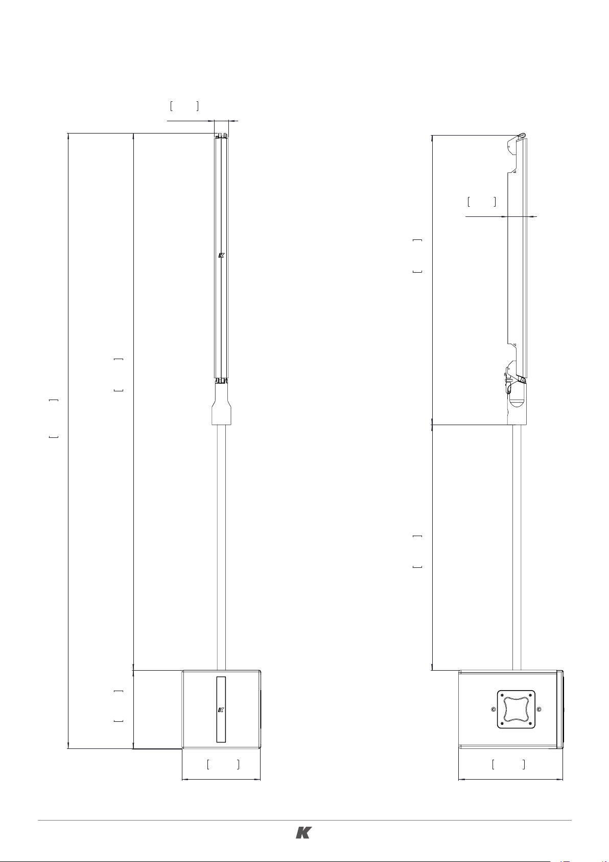
KR PORTABLE SYSTEM Ver. 1.0
2,3in
58,5mm
3,2in
81,1mm
47,3in
1201mm
100,5in
254mm
87,7in
2228mm
40,1in
1017mm
12,8in
326mm
12,8in
326mm
17,0in
433mm
8
Page 9
KR PORTABLE SYSTEM Ver. 1.0
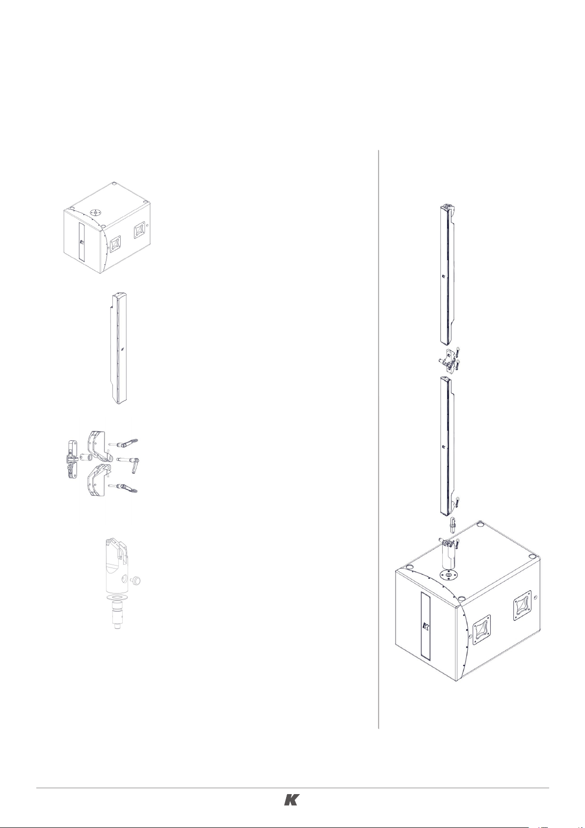
6.2 KR202
This system is composed of 2 x KMT18 18’’ subwoofers + 2 x KK202K plastic cases with 2 x KK102 Kobra
loudspeakers and the mounting hardware. The power cables for the subwoofers and the Speakon cables
to connect the subwoofers to the mid-high elements are also included.
2 x KMT18
Powered 18’’ subwoofer
4 x KK102
1m mid-high element comprised
of 16 x 2” neodymium magnet
transducers
4 x K-JOINT2
Hardware to connect the two
mid-high columns together or to
connect them to the K-FOOT2
accessory
2 x K-FOOT2
Adapter for standing the midhigh columns on the KMT
subwoofers
9
Page 10
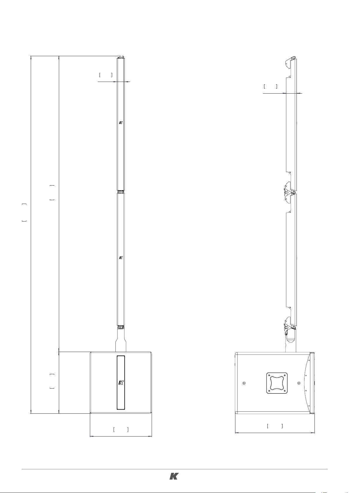
KR PORTABLE SYSTEM Ver. 1.0
2,3in
58,5mm
3,2in
81,1mm
106,0in
2692mm
87,7in
2227mm
18,3in
465mm
18,3in
465mm
23,5in
596,5mm
10
Page 11
KR PORTABLE SYSTEM Ver. 1.0
6.3 KR402
This system is composed of 2 x KMT21 21’’ subwoofers + 2 x KP102K plastic cases each with 1 x KP102
Python loudspeaker and 1 x K-JOINT2 + 2 x KP102KF plastic cases with 1 x KP102 Python loudspeaker,
1 x K-JOINT2 and 1 x K-FOOT2. The power cables for the subwoofers and the Speakon cables to
connect the subwoofers to the mid-high elements are also included.
2 x KMT21
Powered 21’’ subwoofers
4 x KP102
1m mid-high element comprised
of 12 x 3” neodymium magnet
transducers
4 x K-JOINT2
Hardware to connect the two
mid-high columns together or to
connect them to the K-FOOT2
accessory
2 x K-FOOT2
Adapter for standing the midhigh columns on the KMT
subwoofers
11
Page 12

KR PORTABLE SYSTEM Ver. 1.0
108,3in
2751mm
86,5in
2196mm
21,9in
555mm
21,9in
555mm
30,1in
763,5mm
12
Page 13

KR PORTABLE SYSTEM Ver. 1.0
6.4 KR802
This system is composed of 2 x KMT218 dual 18’’ subwoofers + 2 x KY102K plastic cases each with 1
x KY102 Kayman loudspeaker and 1 x K-JOINT2 + 2 x KY102KF plastic cases with 1 x KY102 Kayman
loudspeaker, 1 x K-JOINT2 and 1 x K-FOOT2. The power cables for the subwoofers and the Speakon
cables to connect the subwoofers to the mid-high elements are also included.
2 x KMT218
Powered dual 18’’ subwoofer
4 x KY102
1m mid-high element comprised
of 8 x 4” neodymium magnet
transducers
4 x K-JOINT2
Hardware to connect the two
mid-high columns together or to
connect them to the K-FOOT2
accessory
2 x K-FOOT2
Adapter for standing the midhigh columns on the KMT
subwoofers
13
Page 14

KR PORTABLE SYSTEM Ver. 1.0
105,3in
2675mm
86,4in
2194,9mm
18,9in
480mm
4,6in
116mm
37,4in
949mm
5,3in
134,3mm
23,6in
600mm
14
Page 15

KR PORTABLE SYSTEM Ver. 1.0
7. SYSTEM SETUP
7.1 KR102 SETUP
In this section, we demonstrate how to setup one side of the system. Follow the same procedure to
setup the other side.
1. Adjust the length of the extendable pole and screw it in on the KMT12 subwoofer.
Please note that if you use the extendable stand
you don’t need the short set screw provided
with the K-FOOT2 accessory. You can use it
instead of the extendable stand if you want the
KK102 coloumn to remain closer to the sub.
K-FOOT2 set screw
WARNING
Do not install the system on uneven ground or platform. If the
system is ground stacked on a structure, platform or stage, always
ensure that it can support the total weight of the system.
15
Page 16

KR PORTABLE SYSTEM Ver. 1.0
2. Connect the foot to the speaker with the 8 x 40 piston pin provided. Secure it with the security
block then insert the bracket to set the angles and secure it with the two 5 x 30 piston pins
provided.
Please note that the two joints included in the K-JOINT2
accessory are already mounted on the KK102 speaker when
you purchase the KK102K case.
8 x 40 piston pin
security block
5 x 30 piston pin
• Check that the security sphere of the
piston pin is visible at the opposite
end and cannot accidentally fall out.
• The pin must only be released when
the push button has been pushed.
16
Page 17

KR PORTABLE SYSTEM Ver. 1.0
3. Insert the speaker in the stand, adjust the orientation and tighten the screw on the foot.
Follow the same instructions if
you use the K-FOOT2 set screw
instead of the extendable pole
17
Page 18

KR PORTABLE SYSTEM Ver. 1.0
4. Adjust the angle of the speaker.
4. Connect the KK102 speaker to the KMT12 subwoofer using the provided Speakon cable.
18
Page 19

KR PORTABLE SYSTEM Ver. 1.0
7.2 KR202, KR402, KR802 SETUP
In this section, we demonstrate how to setup one side of the system. Follow the same procedure to
setup the other side. The mounting procedure for the KR402 and KR802 is not dissimilar.
1. Tighten the K-FOOT2 set screw into the subwoofer.
K-FO OT2
2. Connect the foot to one speaker with the 8 x 40 piston pin provided. Anchor it with the security
block.
Please note that the two joints included in the K-JOINT2
accessory are already mounted on the speakers when you buy
a KR system.
8 x 40 piston pin security block
19
Page 20

KR PORTABLE SYSTEM Ver. 1.0
3. Insert the bracket to set the angles and secure it with the two 5 x 30 piston pins provided.
5 x 30 piston pin
4. Position the speaker on the sub.
• Check that the security sphere of the
piston pin is visible at the opposite
end and cannot accidentally fall out.
• The pin must only be released when
the push button has been pushed.
20
Page 21

KR PORTABLE SYSTEM Ver. 1.0
5. Connect the next unit, following the same indications of Steps 2-3.
6. Adjust the orientation and tighten the screw on the foot.
21
Page 22

KR PORTABLE SYSTEM Ver. 1.0
7. Each joint allows the adjustment of the angles from -10° to + 10°. We recommend not to tilt the top
speaker inward, since this would compromise the performace of the system.
22
Page 23

KR PORTABLE SYSTEM Ver. 1.0
8. Connect the mid-high speakers together using the short Speakon cable provided. Connect the bottom
mid-high speaker to the subwoofer using the provided long Speakon cable.
Short Speakon cable
Long Speakon cable
23
Page 24

KR PORTABLE SYSTEM Ver. 1.0
8. AMPLIFIER
8.1 AC POWER
The amplifier module and any audio equipment connected to it (mixing consoles, processors, etc.) must
be properly connected to the AC power distribution, preserving the AC line polarity. Every grounding
point must be connected to a single node or common point using the same cable gauge as the neutral
and line cable. Bad grounding connections between speakers and the rest of the equipment may
produce noise, hum or serious damage to the input/output stages in the system’s electronic equipment.
Before applying AC to any K-array self-powered speaker, ensure
the voltage potential difference between neutral and earth
ground is less than 5 VAC.
8.2 VOLTAGE REQUIREMENTS
The KMT12, KMT18 and KMT21’s switching power supply accommodates AC mains operating at either
115 V or 230 V. The amplifier will continue to operate safely, without interruption, provided that the AC
voltage remains within this nominal range (operating range 90 - 135 V or 190 - 250 V) at 50 to 60 Hz.
The KMT12 Mark I, KMT18 Mark I, KMT21 Mark I and KMT218’s auto-range power supply feature allows
the amplifier unit to operate safely and without audio discontinuity when the AC voltage stays within a
nominal range of 100 - 240 V (operating range 85 - 265 V) at 50 to 60 Hz.
Please verify that your AC main connections are capable of satisfying the power rating for the device.
CAUTION: Do not connect the system to AC mains power
exceeding 265 V. Doing so will cause significant damage to the
device and create serious risk for users!
8.3 CURRENT REQUIREMENTS
The amplifier presents a dynamic load to the AC mains, drawing additional current as operating levels
increase. Different cables and circuit breakers heat up at varying rates, so it is essential to understand
current ratings and how they correspond to circuit breaker and cable specifications. Maximum continuous
RMS current - measured over a period of at least ten seconds - is used to calculate the temperature
increase in cables, which drives the proper size and gauge cable and rating for slow-reacting thermal
breakers. Maximum burst RMS current - measured over a period of approximately one second - is used
to select the rating for fast-reacting magnetic breakers.
For best performance, voltage drops should not exceed 10% at 100 V or 10% at 230 V. The minimum
electrical service amperage required by a K-array loudspeakers system is the sum of their maximum
continuous RMS current. K-array recommends allowing an additional 30% above the minimum amperage
to prevent peak voltage drops at the service entry.
24
Page 25

KR PORTABLE SYSTEM Ver. 1.0
8.4 PROTECTION CIRCUITRY
Both the power supply and the amplifier sections are equipped with several protection circuits.
The power supply protections aim to isolate a faulty section in the electrical power system from the rest
of the device in order to prevent the furtherance of the fault and limit device damage. They comprise
of overcurrent, overvoltage and thermal protections.
Amplifier protections are triggered by audio signal current and voltage – by comparing input and output –
and NTC (Negative Temperature Coefficient) thermistors. A Peak Current Shut Down and a Temperature
Protection Limiter protect the output stage.
High frequency stationary signals, like steady sinusoidal signals – improperly referred to as continuous
or permanent signals – with high amplitude tend to stress the amplifier section of the modules as well
as the loudspeaker’s voice coils. When a high frequency stationary loud signal is fed into the amplifier,
a dedicated Limiter confines its mean current depending on its level and frequency.
25
Page 26

KR PORTABLE SYSTEM Ver. 1.0
8.5 REAR PANEL SETTINGS: KMT12 I, KMT18 I, KMT21 I, KMT218
19
14
15
1
5
4
2
3
9
5.5 A
2.9 A
16
10
14 A
1.6
16 A
230
3.5
17
11 12
20
13
18
6
7
8
26
Page 27

KR PORTABLE SYSTEM Ver. 1.0
1) CH1 Line Input. XLR line level input with +4 dBu sensitivity.
2) CH2 Mic/Line Input. XLR input, with selectable sensitivity for Mic (-30 dBu) or Line (+4 dBu).
3) Mic/Line switch. Selects CH2 input sensitivity for Mic ( -30 dBu) or Line ( +4 dBu) level.
4) Phantom Power switch. Turns phantom power (48V) on/off on CH2 input.
5) Limiting LEDs. Independent LEDs for the CH1 and CH2 inputs, which blink when the optical limiter
engages to protect the corresponding preamp circuit. Limiter threshold is +5 dBu.
6) CH1 Parallel Line Out. XLR parallel output providing a direct signal from the CH1 Line Input. This
output cannot be processed or controlled via the K-Framework software.
7) CH2 Parallel Line Out / DSP Out. When the DSP Out switch is not pressed (off), this connector
provides a direct signal from the CH2 input. Press the DSP Out switch to use this output as an
auxiliary XLR balanced output controlled via the K-Framework software.
8) DSP Out Switch. See point 7.
9) AES/EBU Digital Input. XLR input connector for two-channel AES/EBU digital audio, accepting
sample rates up to 96 kHz.
10) AES/EBU Digital Output. XLR output, providing two-channel digital audio from AES/EBU Input,
This output cannot be processed or controlled via the K-Framework software.
11) REMOTE RS485 Link Input. XLR input for connecting the KMT from another RS485 device in a
K-Framework network. RS485 Link Input can also be used to connect a computer running the
K-Framework software (requires K-USB USB-to-RS485 adapter).
12) REMOTE RS485 Link Output. XLR output for connecting additional RS485 devices in a K-Framework
network.
13) REMOTE USB Input. Connects a computer running the K-Framework software, for remote control
of the KMT. Users can manage an entire network of RS485 devices with one PC connected via
USB.
14) Speaker Out. Powered Speakon output, used to drive passive speakers, like a mid-high module
or a passive subwoofer.
15) Power switch. Turns the KMT system on and off.
16) AC Input. PowerCon input for AC power.
17) AC Link. PowerCon output for feeding AC mains power to additional K-array components with a
PowerCon AC input socket.
18) Power On LED. Indicates the system is ON.
19) Touch Screen Control Panel. Provides access to the main functions of the onboard DSP (see
Section 8)
20) 5 Volt Power Connector. Provides 5VDC/500mA to power e-fun accessories.
IMPORTANT NOTE
By default, the analog channel CH2 and the digital channel CH4 are not routed
to any output. To activate them, go to the Matrix Page on the LCD screen (see
Chapter 8).
27
Page 28

KR PORTABLE SYSTEM Ver. 1.0
8.6 REAR PANEL SETTINGS: KMT12, KMT18, KMT21
19
14
15
1
5
4
2
3
9
16
10
17
11 12
13
18
6
7
8
28
Page 29

KR PORTABLE SYSTEM Ver. 1.0
1) CH1 Line Input. XLR line level input with +4 dBu sensitivity.
2) CH2 Mic/Line Input. XLR input, with selectable sensitivity for Mic (-30 dBu) or Line (+4 dBu).
3) Mic/Line switch. Selects CH2 input sensitivity for Mic ( -30 dBu) or Line ( +4 dBu) level.
4) Phantom Power switch. Turns phantom power (48V) on/off on CH2 input.
5) Limiting LEDs. Independent LEDs for the CH1 and CH2 inputs, which blink when the optical limiter
engages to protect the corresponding preamp circuit. Limiter threshold is +5 dBu.
6) CH1 Parallel Line Out. XLR parallel output providing a direct signal from the CH1 Line Input. This
output cannot be processed or controlled via the K-Framework software.
7) CH2 Parallel Line Out / DSP Out. When the DSP Out switch is not pressed (off), this connector
provides a direct signal from the CH2 input. Press the DSP Out switch to use this output as an
auxiliary XLR balanced output controlled via the K-Framework software
8) DSP Out Switch. See point 7.
9) AES/EBU Digital Input. XLR input connector for two-channel AES/EBU digital audio, accepting
sample rates from 32 kHz – 96 kHz.
10) AES/EBU Digital Output. XLR output, providing two-channel digital audio from AES/EBU Input,
at a sample rate of 48 kHz. This output cannot be processed or controlled via the K-Framework
sof tware.
11) REMOTE RS485 Link Input. XLR input for connecting the KMT from another RS485 device in a
K-Framework network. RS485 Link Input can also be used to connect a computer running the
K-Framework software (requires K-USB USB-to-RS485 adapter).
12) REMOTE RS485 Link Output. XLR output for connecting additional RS485 devices in a K-Framework
network.
13) REMOTE USB Input. Connects a computer running the K-Framework software, for remote control
of the KMT. Users can manage an entire network of RS485 devices with one PC connected via
USB.
14) Speaker Out. Powered Speakon output, used to drive passive speakers, like a mid-high module
or a passive subwoofer.
15) Power switch. Turns the KMT system on and off.
16) AC Input. PowerCon input for AC power.
17) AC Link. PowerCon output for feeding AC mains power to additional K-array components with a
PowerCon AC input socket.
18) Power On LED. Indicates the system is ON.
19) Touch Screen Control Panel. Provides access to the main functions of the DSP on board (see
Section 9).
29
Page 30

KR PORTABLE SYSTEM Ver. 1.0
8.7 RS485 NETWORK
The RS485 Link Input and the RS485 Link Output on the rear panel allow the creation a network of
K-array devices that users can manage with a PC running the K-Framework software. All devices can be
linked with standard XLR cable.
The PC can be connected to the network either with USB cable or XLR cable (requires K-USB USB-toRS485 adapter accessory) as shown in the diagrams below.
USB cable
PC connected via USB cable
K-U SB
5.5 A
2.9 A
14 A
1.6
16 A
230
3.5
XLR cable
5.5 A
2.9 A
14 A
1.6
16 A
230
3.5
XLR cable
5.5 A
2.9 A
14 A
1.6
16 A
230
3.5
XLR cable
5.5 A
2.9 A
14 A
1.6
16 A
230
3.5
XLR cable
5.5 A
2.9 A
14 A
1.6
16 A
230
3.5
XLR cable
PC connected via XLR cable + K-USB accessory
Attention: Make sure that you have set a different ID number on each device
before connecting them to a PC running the K-framework. See the INFO section in
Chapter 9 for details.
5.5 A
2.9 A
14 A
1.6
16 A
230
3.5
30
Page 31

KR PORTABLE SYSTEM Ver. 1.0
9. TOUCH SCREEN FUNCTIONS
9.1 TOUCH SCREEN FUNCTIONS: KMT12 I, KMT18 I, KMT21 I, KMT218
The main functions of the onboard DSP can be managed with the integrated touch screen. Functions
are grouped into six pages, shown as icons on the Home page.
HOME PAGE
To reach the Home Page from any other page,
touch the Home button.
LEVELS
MATRI X
The Levels page allows users to independently manage
the amplitude of the four input channels and the two
output channels of the amplifier.
CH1 and CH2 are the two analog inputs, while CH3 and
CH4 are the two AES/EBU digital input channels. A1
controls the output level sent to the subwoofer and A2
controls the output level sent to the speakers connected
to the Speaker Out.
Click the arrow button on the top right corner to switch
between the Input Levels Page and the Output Levels
Page.
The Matrix Page allows users to manage the routing of
the four input channels to the subwoofer, to the speaker
connected to the Speaker Out and to the XLR DSP Out.
In the example shown here, the analog signal on the input
Channel 1 and the digital signal on the input Channel 3 are
sent to the subwoofer while the analog signal on the input
Channel 2 and the digital signal on the input Channel 4
are sent to the speakers connected to the Speaker Out.
All inputs channels are also summed and sent to the XLR
DSP Out.
31
Page 32

KR PORTABLE SYSTEM Ver. 1.0
DEL AY
The Delay Page allows users to independently set the
delays for the two output channels driving the subwoofer
and the speakers connected to the Speaker Out (up to
3.5 m) and for Channel 1 and Channel 2 input channels
(up to 114 m).
Pressing on a delay value, users can set the delay in
milliseconds or meters. Press the OK button to return to
the Delay Page.
CONFIGURATION
When you buy a KR system, the correct preset is already
loaded and the system is ready to play.
If necessary, the system can be dismounted and the
subwoofer can be used to drive different K-array passive
speakers. In this case, go to the Configuration Page
and press the SETUP button. Insert the model and the
number of speakers connected to the Speaker Out.
Press the NEXT button on the top right corner. Press the
APPLY button and the DSP will automatically adjust the
output gain and the crossover to match the requirement
for the speakers connected.
Warning: If you are using speakers with selectable impedance, pay
attention to set the value indicated in the Configuration Page!
32
Page 33

KR PORTABLE SYSTEM Ver. 1.0
PRESET
The Preset Page allows users to load presets stored
onboard.
INFO
The Info Page contains information about the
current software and firmware, the current preset
loaded and the Board ID of the device.
The Board ID is a number which identify the device
when it is connected in a K-framework network
(see Paragraph 7.6). Make sure that each device in
the network has a different ID number.
33
Page 34

KR PORTABLE SYSTEM Ver. 1.0
9.2 TOUCH SCREEN FUNCTIONS: KMT12, KMT18, KMT21
HOME PAGE
The main functions of the onboard DSP can be managed with
the integrated touch screen. Functions are grouped into six
pages, shown as icons on the Home Page.
To reach the Home Page from any other page,
touch the Home button.
INPUT PAGE
OUTPUT PAGE
ROUTING PAGES
The Input Page allows users to independently manage the
amplitude of all the four input channels.
The Output Page allows users to independently control the
amplitude of the signal routed to the subwoofer, the speaker
output and the XLR DSP output.
Three Routing pages allow users to manage the routing of the
four input channels to the three outputs (subwoofer, speaker
output and XLR DSP output) as well independently set output
volume and delay for each output.
The delay values set in the Routing pages are summed to the
global delay assigned on the Delay Page.
The arrow buttons on the top right corner of the screen provide
access to individual Routing pages for the subwoofer, speaker
output and XLR DSP output.
PRESET PAGES
Notes: The XLR DSP Page does not provide control over delay
for this output.
Two Preset pages allow users to load presets stored onboard.
The arrow buttons on the top right corner of the screen provide
access to the Factory and User Preset Pages. The arrows are
also used to scroll through, select and load one of the available
presets.
34
Page 35

KR PORTABLE SYSTEM Ver. 1.0
INFO PAGE
DEL AY PAGE
The Info Page contains information about the current software
and firmware, and the Logical ID of the KMT module. Make sure
that each device in the network has a different ID number.
The Delay Page allows users to independently set the delays
for the speaker system (subwoofer and speaker output). This
delay is summed with the delays from the Routing pages of
subwoofer and speaker output. The COARSE and FINE controls
allow users to change the delay in larger and smaller steps.
Notes: The delay control does not affect the XLR DSP out.
Delay for this output line can only be managed through the
K-Framework dedicated controls.
35
Page 36

KR PORTABLE SYSTEM Ver. 1.0
9. SERVICE
To obtain service:
1) Contact the official K-array distributor in your country. Your local distributor will direct you to the
appropriate service center.
2) If you are calling for service, please have the serial number(s) of the unit(s) available for reference.
Ask for Customer Service, and be prepared to describe the problem clearly and completely.
3) If the problem cannot be resolved over the phone, you may be required to send the unit in for
service. In this instance, you will be provided with an RA (Return Authorization) number which
should be included on all shipping documents and correspondence regarding the repair. Shipping
charges are the responsibility of the purchaser.
Any attempt to modify or replace components of the device will invalidate your warranty. Service must
be performed by an authorized K-array service center.
Cleaning:
Use only a soft, dry cloth to clean the housing. Do not use any solvents, chemicals, or cleaning
solutions containing alcohol, ammonia, or abrasives. Do not use any sprays near the product or
allow liquids to spill into any openings.
36
 Loading...