

Page 1
KMT21
USER’S MANUAL
English
Page 2

REV. A2
Page 3

Contents
SYMBOLS 5
1. INTRODUCTION 7
2. APPLICATIONS 7
3. KEY FEATURES 7
4. UNPACKING 8
5. WARRANTY 8
6. SAFETY 8
7. PHYSICAL 9
8. AMPLIFIER 10
8.1 AC POWER CONNECTOR 10
8.2 VOLTAGE REQUIREMENT 10
8.3 CURRENT REQUIREMENT 10
8.4 REAR PANEL 11
8.5 TOUCH SCREEN FUNCTIONS 13
8.6 AUDIO INPUT CONNECTOR WIRING 14
8.7 AMPLIFICATION AND PROTECTION CIRCUITRY 14
9. K-FRAMEWORK 15
9.1 SYSTEM REQUIREMENTS 15
9.2 INSTALLATION AND SETUP 15
9.4 USER TABS: 18
INPUT TAB 19
ROUTING TAB 20
DELAY TAB 20
OUTPUT TAB 21
10. SERVICE 22
11. SPECIFICATIONS 23
12. DECLARATION OF CONFORMITY 24
KMT21
REV. A
3
Page 4

KMT21
REV. A4
Page 5
KMT21
SYMBOLS
K-array declares that this device is in compliance with applicable CE standards and
regulations. Before putting the device into operation, please observe the respective
country-specic regulations!
WEEE
Please dispose of this product at the end of its operational lifetime by bringing it to your local
collection point or recycling center for such equipment.
This symbol alerts the user to the presence of recommendations about the product’s use
and maintenance.
REV. A
Warning! Dangerous voltages: RISK of electric shock.
This symbol alerts the user to the presence of recommendations about product’s use and
maintenance.
This device complies with Restriction of Hazardous Substances Directive.
5
Page 6

KMT21
REV. A6
Page 7

KMT21
1. INTRODUCTION
The K-array KMT21 is a full-featured audio system, featuring a 21” powered subwoofer, programmable on-board
DSP and multiple analog and digital inputs and outputs for creating a wide array of speaker congurations.
The KMT 21 features an integrated touch screen, providing intuitive control over the main DSP functions: input
/ output levels, signal routing, offset delays for subwoofer and speakon output (up to 12 ms., each) and overall
system delay (up to 330 ms.). All DSP functions, including EQ, can also be remote controlled via software over
USB or RS485 (3-pin XLR).
The KMT series provides two balanced analog line level inputs and a two-channel AES/EBU digital input. An
integrated class D amplier delivers 2 x 2000 W at 4Ω, with a max THD of 1% (EIAJ test @ 1KHz). The KMT21
features multiple analog and digital outputs, including a Speakon output to connect a wide array of passive
speakers including mid-high modules (KP52, KP102) or additional passive subwoofers (KMT21P). To optimize
performance, the on-board DSP includes up to 40 programmable presets. The rst 8 have been designed by
K-array, the additional 32 slots can be used to create, save, and store personal presets using the K-framework
software.
The KMT series’ unique four-corner port conguration provides symmetrical back loading to the speakers, for
extended bass response with very low distortion. The port conguration also provides incredible structural strength
to the cabinet, despite its light weight. Pocket handles and an M20 thread mount position for attaching mid-high
speakers makes the Redline series convenient to use and ideal for medium throw applications in theaters, concert
halls, and Audio/Video installations.
All KMT components are designed by K-array and custom-made under K-array’s quality control system.
2. APPLICATIONS
• Theatrical sound reinforcement
• Concert halls, clubs, houses of worship
• Portable and installed audio-visual systems
• Cinema and special effects
REV. A
3. KEY FEATURES
• Unique performance-to-size ratio
• Direct radiating, long excursion driver
• Ultra fast set-up and dismantling system
• Fitted with integrated handles and castors
• Analog and digital AES/EBU inputs
• Remote software control over USB and RS485
• Optimized for use with KP52 / KP102, KMT21P
7
Page 8
KMT21
4. UNPACKING
Each K-array loudspeaker is built to the highest standard and thoroughly inspected before leaving the factory.
Upon arrival, carefully inspect the shipping carton, then examine and test your new loudspeaker. If you nd any
damage, immediately notify the shipping company. Only the consignee may institute a claim procedure regarding
the system’s electronic equipment.
5. WARRANTY
K-array systems are warranted against manufacturing defects in materials or craftsmanship over a period of 2
years from the date of original purchase. During the warranty period K-array will, at its discretion, either repair or
replace products which prove to be defective provided that the product is returned in its original packaging, shipping
prepaid, to an authorized K-array service agent or distributor. K-array cannot be held responsible for defects caused
by unauthorized modications, improper use, negligence, exposure to inclement weather conditions, acts of God
or accidents, or any use of this product that is not in accordance with the instructions provided by K-array. K-array
is not liable for consequential damages. This warranty is exclusive and no other warranty is expressed or implied.
This warranty does not affect your statutory rights.
6. SAFETY
WARNING
• Professional loudspeakers are capable of
producing extremely high sound levels and should
be used with care. Hearing loss is cumulative and
can result from extended exposure to levels in
excess of 90dB.
• Always use loudspeaker systems in a safe manner.
Never stand close to loudspeakers driven at high
volume.
• Only install the speaker in a location that can
structurally support the weight of the unit. Doing
otherwise may result in personal injury and property
damage.
• The system should only be suspended by qualied
personnel, following safe rigging practices. If
there is any doubt, seek professional help from
architects, structural engineers or other specialists
before proceeding.
• Do not operate the speaker for an extended period
of time if the sound is distorted. This is an indication
of malfunction, which can cause heat build-up and
result in a re.
• Only connect the power supply to an appropriate
power adapter.
• Do not install the speaker in wet or humid locations
without using weather protection.
• Do not allow water or any foreign object to get inside
the speaker. Do not put objects containing liquid on,
or near, the unit.
• To reduce the risk of overheating the amplier,
avoid exposing it to direct sunlight. Do not install the
unit near heat emitting appliances, such as a room
heater or stove.
• Never place open ame sources, such as lighted
candles, near the device.
• The speaker should be placed in a location that
does not interfere with its proper cooling.
• Do not attempt to disassemble the unit. The unit
contains no user-serviceable parts. Repairs should
be performed only by factory trained service
personnel.
• Be sure that the adapter has the correct voltage
value.
REV. A8
Page 9
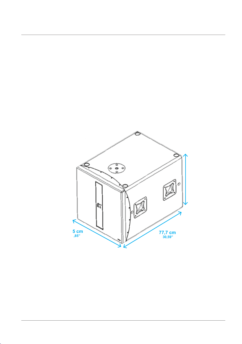
7. PHYSICAL
KMT21
55,5 cm
21,85”
KMT21
REV. A
55,5 cm
21,85”
77,7 cm
30,59”
weight: 49 kg (103.03 lbs)
9
Page 10

KMT21
8. AMPLIFIER
8.1 AC POWER CONNECTOR
The amplier module and any audio equipment connected to it (mixing consoles, processors, etc.) must be
properly connected to the AC power distribution, preserving AC line polarity. All grounding points should be
connected to a single node or common point, using the same cable gauge as the neutral and line cables. Bad
grounding connections within an audio system can produce noise, hum and/or serious damage to the input/
output stages in the system’s electronic equipment.
Before applying AC to any K-array self-powered speaker, be sure that the voltage
potential difference between neutral and earth ground is less than 5 VAC.
8.2 VOLTAGE REQUIREMENT
The KMT21 will operate safely, without interruption, provided the AC voltage remains within 85V- 268V, at
50 or 60 Hz. Please verify that your AC mains connection is capable of satisfying the power ratings for the
device.
CAUTION
Do not connect the system to AC power mains exceeding 270V. Doing so will
cause signicant damage to the device and create serious risk for users!
8.3 CURRENT REQUIREMENT
The KMT21 presents a dynamic load to the AC mains, drawing additional current as operating levels increase. Different cables and circuit breakers heat up at varying rates, so it is essential to understand current
ratings and how they correspond to circuit breaker and cable specications. Maximum continuous RMS
current - measured over a period of at least ten seconds - is used to calculate the temperature increase in
cables, which drives the proper size and gauge cable and rating for slow-reacting thermal breakers. Maximum burst RMS current - measured over a period of approximately one second - is used to select the rating
for fast reacting magnetic breakers.
For best performance, voltage drops should not exceed 10% at 115V or 5% at 230V.
REV. A10
Page 11

KMT21
The minimum electrical service amperage required by a K-array loudspeakers system is the sum of their
maximum continuous RMS current. We recommend allowing an additional 30% above the minimum amperage
to prevent peak voltage drops at the service entry.
KMT21 max continuous apparent power (VA)
670VA(>10 sec) - 2600VA (<1 sec)
8.4 REAR PANEL
20
11
12
13
1
6
4
3
7
2
5
9
8
10
19
18
14
15
16
17
REV. A
11
Page 12

KMT21
1) CH1 Line Inp ut. XLR li ne level input with + 4 dBu sens itivit y.
2) C H2 Mic /Line In put. XLR i nput, wi th selectable s ensiti vity fo r Mic (-30 d Bu) or Line (+4 dB u).
3) C H1 Paralle l Line Out . XLR para llel out put, prov iding a direct sig nal from t he CH1 Line In put. Thi s output c annot
be proc essed or contro lled via t he K-Fram ework softwa re
4) Phantom Powe r switch. Turn s phantom p ower (48V ) on/off on CH1 and CH2 i nputs.
5) Mic /Line switch. S elect s CH2 inpu t sensitivity fo r Mic ( -3 0 dBu) or Line ( + 4 dBu) level..
6) Li miting L EDs. Independent LEDs for t he CH1 and CH 2 inputs, which bl ink when t he optic al limiter engage s to
protect the corresponding preamp circuit. Limiter threshold is +5 dBu.
7) DSP O ut. Aux iliar y XLR balanced ou tput, c ontrol led via th e K-Frame work sof twar e. Users c an sele ct the si gnal
routed to this output and manage its amplitude and EQ individually.
8) D SP Out Powe r switch. Turns phantom power (48V ) on and of f on the DS P out. Phan tom power c an be eng aged
to drive additional wireless signal transmitters/receivers.
9) A ES/EBU D igita l Input. X LR input c onnector for tw o-c hannel A ES/EBU digital audio, acceptin g sample r ates
from 32 k Hz – 96 k Hz.
10) AES/ EBU Dig ital Output. XL R output , providi ng two -cha nnel digital audi o from AES/EBU Input, at a sa mple rate
of 48 kHz. T his outp ut canno t be proc essed or contro lled via t he K-Fram ework so ftwa re.
11) REMOTE RS485 Link I nput. XLR input fo r conne cting th e KMT from anothe r RS48 5 device i n a K-Framew ork
network. RS4 85 Link In put can al so be used t o connect a computer runn ing the K- Framewor k soft ware (req uires
K-USB USB-to-RS485 adapter).
12) REMOTE RS 485 Link O utput. XLR outp ut for connecti ng additional RS 485 devices in a K- Framework network.
13) R EMOTE USB Input. C onnect s a compu ter runn ing the K- Framewor k soft ware, fo r remote c ontrol of the KMT.
Users c an manag e an entire n etwor k of RS48 5 devices with on e PC conn ected vi a USB (see RS 485 Net work
diagram, below).
14) S peaker Ou t. Powere d Speakon o utput, u sed to dri ve passive speaker s, like a KP se ries mi d-hig h module o r a
KMT series passive subwoofer
15) Power swit ch. This s witch turns the K MT system o n and off.
16) AC Inpu t. Powerc on input f or AC power. See p. 11 for vo ltage an d power requireme nts.
17) AC Link. Powe rcon ouput for fee ding AC mai ns power to additional K-array comp onents w ith a power con AC
input socket.
18) Extension Connector. Multi-pin connector for various K-array extension modules, for wireless control and audio
transm ission , memor y exten sion, di gital s ignal en coding and audi o repro ductio n.
19) Power O n LED. Indi cates th e system is O N.
20) TOUCH SCREEN C ontrol p anel. Provides ac cess to t he main function s of the DSP on board (se e Section 8.5)
RS485 XL R link
USB Conn ection fr om a PC
RS485 XL R link RS485 XL R link RS485 XL R link
RS48 5 networ k
REV. A12
Page 13

8.5 TOUCH SCREEN FUNCTIONS
KMT21
HOME PAGE
INPUT PAGE
OUTPUT PAGE
ROUTING PAGES
The main functions of the onboard DSP can be
managed with the integrated touch screen. Functions
are grouped into six pages, shown as icons on the
Home page.
To reach the Home page from any other page,
touch the Home button.
The Input page allows users to independently manage
the amplitude of all the four input channels
The Output page allows users to independently control
the amplitude of the signal routed to the Subwoofer, the
Speaker Output and the XLR DSP Output.
Three Routing pages allow users to manage the routing of the four input channels to the three outputs
(Subwoofer, Speaker Out and XLR DSP Out) as well
independently set output volume and delay for each
output.
The delay values set in the Routing pages are summed
to the global delay assigned on the Delay page.
The arrow buttons on the top right corner of the screen provide access to individual Routing pages for the
Subwoofer, Speaker Out and XLR DSP Out.
REV. A
PRESET PAGES
INFO PAGE
Notes: The XLR DSP page does not provide control
over delay for this output.
Two Preset pages allow users to load presets stored
on-board. The arrow buttons on the top right corner
of the screen provide access to the Factory and User
preset pages. The arrows are also used to scroll
through, select and load one of the available presets.
The Info page contains information about the current
software and rmware, and the Logical ID of the KMT
module. The Logical ID is automatically assigned
to the KMT unit when connected to a K-Framework
network.
13
Page 14

KMT21
DELAY PAGE
8.6 AUDIO INPUT CONNECTOR WIRING
The Delay page allows users to independently set
the delays for the speaker system (Subwoofer and
Speaker Out). This delay is summed with the delays
from the Routing pages of Subwoofer and Speaker
Out. The COARSE and FINE controls allow users to
change the delay in larger and smaller steps.
Notes: The delay control does not affect the XLR
DSP out. Delay for this output line can only be
managed through the K-Framework dedicated
controls.
The Audio section includes parallel LINK, which
allows users to distribute an audio signal to
multiple units. Up to 30 different modules can be
connected in parallel on the same balanced line
(with a source output impedance of 600 ohm).
CH 1 Line Input (female, balanced XLR) is
wired in parallel to CH1 Line Parallel Out (male,
balanced XLR). To create your own audio cables,
please use the following wiring diagrams:
8.7 AMPLIFICATION AND PROTECTION CIRCUITRY
The KMT21 is powered by a 2-channel digital amplier with 2000 W output power per channel (EIAJ test).
The KMT21’s amplier functions, including crossovers, equalization, phase response, and driver protection,
are controlled by an on-board DSP processor.
KMT series ampliers are equipped with several protection circuits to prevent damage. Two independent
audio limiters – Clip Limiter and Average Power Limiter – protect the internal circuitry against overload. A
Peak Current Shut Down protects the output stage with a tripping point at 35A. If tripped, Peak Current Shut
Down will reset after 2 seconds. A Temperature Protection Limiter also ensures the output stage stays below
a temperature of 85° C (approximate temperature of output power device).
INPUT PARALLEL
hot
2
1
3
cold
XLR connecto r
grd
grd
OUTPUT
1
3
cold
hot
2
REV. A14
Page 15

9. K-FRAMEWORK
9.1 SYSTEM REQUIREMENTS
SYSTEM REQUIREMENTS:
Operating Syst em: Windows XP / Vist a / 7
CPU: Intel Pentium Dual Core
Memor y: 2 GB
REQUIRED COMPONENTS:
Microsoft .NET Framework 4:
http://www.microsoft.com/download/en/details.aspx?id=17718
Micro soft V isual C++ 2010 Redist ribut able Pac kage (x8 6):
http://www.microsoft.com/download/en/details.aspx?id=5555
Micro soft V isual C++ 2010 Redist ribut able Pac kage (x6 4):
http://www.microsoft.com/download/en/details.aspx?id=14632
9.2 INSTALLATION AND SETUP
To download your free K- Framewor k soft ware, pl ease navi gate to the K- array “ Soft ware Dow nload ” page loc ated at
http://usa.k-array.com/en/download/software.html
Downlo ad the la test 32- or 64- bit inst aller. Decompre ss the . zip file and ext ract the “K-Framewor k.setup” instal ler file.
- Window s Vista and Windows 7 users c an insta ll the sof twar e by simply r unning t he K-Fram ework. setup fi le.
- Window s XP user s are requi red to install the n ecess ary US B driver s separately:
KMT21
1) Open th e “Control Panel ” menu fr om the “S tart M enu” or “ My Computer.”
2) O pen “Device Manager ” from the Control Panel and ex pand the “USB contro llers” (or “Universal Serial Bus
controllers”) sub-menu.
REV. A
15
Page 16

KMT21
5
6
3) R ight cli ck on the upper “K- Array_ Dsp01” ob ject and select “ Drive r Update” t o launch the “Har dware Update
Wizard”
4) When asked t o allow the onlin e search, selec t “Not n ow” and click “ Next .”
5) Whe n asked for t he drive r’s loca tion, se lect “I nstall f rom a list o r specific loc ation.”
6) In t he searc h and inst allati on optio ns windo w, select “ Search for the be st driver i n this loc ation” a nd chec k the
“Incl ude this locat ion in th e search” checkbox, then brows e for the d river ’s folder. Th e path should read:
C:\ProgramFiles\K-array\K-framework\drivers_rev02
Selec t the new d river f ile and c lick “ Next.”
7) If wa rned ab out a failed “W indows Logo” tes t, please ignor e and cli ck “Next”.
8) h e first p art of dr iver inst allati on is now c omplete, and the “unknown” K- Array_ Dsp01 po rt has b een updat ed to
read “K- Array _Dsp 01 A.” Click on “Fini sh” and rep eat the sa me proc edure for the second drive r.
9) N ow you can see that ins ide the Device Ma nager Wi ndow bot h device s now have uni que names (K-Ar ray
_Ds p0 1 A a nd K- Ar ray _ Dsp 01 B), and th e al ert sy mb ol is no l on ge r pre se nt. You ar e no w 100 % re ady t o ge t st art ed!
REV. A16
Page 17

At star tup K-Fra mework w ill show t he follo wing win dow:
KMT21
A5
A3
A2
A1
A4
A1) Connected Device s Indicator shows the numbe r of detected conn ected dev ices. N .B.: At sta rtup, the indic ator
will sho w 0 device s, even if one o r more uni ts are co nnecte d. To detect all c onnect ed devic es, clic k the “Connect ”
button (A2).
A2) Connect Button detects connected devices.
A3) Demo Butto n activates the dem o mode of K- Framewor k. In thi s mode, all d evices t hat can be mangaed w ith the
K-Framework sof twar e appear in the Conn ected Devices M enu on the l eft, so t hat the us er can nav igate thr ough all
the dedi cated tabs and have a g limpse of t he different fu nctions availab le for eac h unit.
A4) K-array Device Lis t displays all devic es presently co nnecte d to the net work.
N.B.: at st artup the List will be empt y, even if one or m ore unit s are connected. To dete ct all co nnecte d device s, just
click t he “Connect” button (A2).
A5) Account Button ope ns the Ac count Settings Window where users can ins ert Us er Name an d Passwor d to acce ss
the K-A rray Com munity and the shared preset datab ase.
A6) Zoom Button s zoom in (+) and out (-) of the window view.
A6
img. A
Click th e Conne ct button to detec t all pres ently co nnecte d device s.
All dete cted devi ces wil l appear i n the K-A rray Devi ce list, as shown in I mage B (be low):
REV. A
17
Page 18

KMT21
9.4 USER TABS:
HOME
B1
B2
B3
img. B
B1) Connected Device Name.
B2) Device Menu Button s hows and hides the d evice me nu.
B3) Device Menu d isplays t he basic in format ion about the devi ce and the s hortcuts to op en all avail able Edit ing
Tab s.
img. C
From the Home window, users can access the dedicated tabs, which follow the signal ow from input stage
to output stage.
REV. A18
Page 19

INPUT TAB
Allows users to independently manage the EQ and gain of the four input channels
D1
D2
D4
D3
D5
D6
D7
D8
KMT21
D1) Frequency respons e display. Sho ws the fre quency r espons e curve r esulting from th e filter s set in the I nput EQ win dow
(below).
D2) npu t EQ window butto n. Opens the Inp ut EQ window, where u sers can set thr ee parametri c filters for ea ch input channe l.
Input Volume butto ns. They re gulate th e amplit ude of each input cha nnel
D3) Inp ut Volume but tons. Adjusts th e amplitude of the in put chan nel
Input EQ wi ndow
D4) Input Volume disp lay. Shows the g ain or red uction curren tly appl ied to the c hannel. Users can directly set the d esired
amount of g ain in the I nput Volume display, inst ead of usin g the Inpu t Volume but tons
D5) Filter t ype menu
D6) Filter frequency
D7) Filter Q
D8) Filter boost
REV. A
img. D
19
Page 20

KMT21
ROUTING TAB
E1) Routing switch button. When lighted, the signal coming from the corresponding input on the left
column is routed to the corresponding output on the top row.
E1
img. E
DELAY TAB
Allows users to independently manage the delay applied to the three output channels.
F2F1 F3
img. F
F1)
Global Delay buttons. Adjusts the amount of overall d elay applied to both th e subwo ofer and sp eakon o utput
(which c an feed pa ssive spe akers, i.e .: mid-h igh modu les or an ad dition al subwoo fer modules).
F2) Glo bal Dela y dis play. Show s th e amo unt o f del ay cu rre ntl y app lie d to th e ove ral l system (subwo ofe r + spe ako n
output), b oth in mill iseco nds and in meters. Us ers can directl y write the desire d amount of delay in mil lisec onds or
meters, instead of using t he Glob al Delay b uttons.
F3) Dedic ated Delay s. Butto ns and displays in this section have exac tly the sam e functi ons as the ones i n the
Overall delay section, but each set is dedicated exclusively to one output channel. From top to bottom: subwoofer
delay, speako n output d elay, and XLR D SP outpu t delay.
REV. A20
Page 21

KMT21
OUTPUT TAB
Allows users to independently manage the EQ, polarity, gain and limiting threshold of the three output channels.
G11
G6
G1
G3 G4 G5
G10G9G8G7
G2
img. G
G1) Frequency resp onse display. Show s the frequen cy response cu rve resulti ng from the fi lters set in the I nput EQ window.
G2) Output EQ windo w butto n. Opens the Out put EQ wi ndow, where users can set up to six p aramet ric fi lters for each
output channel.
G3) Phase button. Inverts the channel’s signal polarity (180° phase rotation).
G4) Outp ut Volume buttons. A djusts the amplit ude of eac h output c hannel.
G5) Out put Volume display. Show s the gain b oost or re duction currently app lied to each output channe l. Users c an
direct ly write the desired amount of volume i nside th e Output Vol ume display, instead of using the O utput Volume butto ns.
N.B.: T he XLR DS P secti on of the Ou tput tab does not provide the ma nagemen t of any limi ter for this output.
Output EQ window
G6) Frequency response curve
G7) Filter typ e menu
G8) Filter frequency
REV. A
G9) F ilter bo ost
G10) Filter Q
G11) Filter select button
21
Page 22

KMT21
10. SERVICE
To obtain ser vice:
1) Contact t he off icial K- array di stribu tor in your c ountr y. Your local dis tribut or will di rect you to the appropriate servi ce cent er.
2) If you are calling fo r serv ice, ple ase have the s erial number(s) of the u nit(s) available for refe rence. A sk for Cus tomer Servic e,
and be prepared to describe the problem clearly and completely.
3) If the pro blem can not be res olved over t he phone , you may be req uired to se nd the uni t in for ser vice. In this inst ance, yo u will
be provi ded with a n RA (Ret urn Auth orization) numbe r which should be include d on all ship ping document s and cor respondence
regarding the repair. Shipping charges are the responsibility of the purchaser.
Any atte mpt to modi fy or re place c ompone nts of the d evice wi ll invalid ate your war ranty. Servic e must be perfor med by an
author ized K-array ser vice c enter.
Cleaning:
Use only a s oft, dr y clot h to clean t he housi ng. Do not use any solve nts, che micals , or cleaning solu tions
conta ining alc ohol, a mmonia, or abrasives. Do no t use any spr ays near the produc t or allow liquids to s pill
into any openings.
REV. A22
Page 23

11. SPECIFICATIONS
KMT21
KMT21
Acoustics
Speak ers pow er
handling
Maximum power 2800 w
Impedance 4Ω
Frequency range 30Hz - 150 Hz +/- 3dB (preset depend ent)
SPL 1W/1mt 102 dB
Maximum SPL 132 dB continuous - 138 d B peak
1800 w
(EAS)
1
2
Coverage
Omni
Crossover
Typ e DSP controlled
Frequency 150 Hz maximum (pre set dependent)
Transducers
1 x 21” Neodym ium spea kers with 4”
voice coil
Audio Input
Analog
Connectors
Connectors
2 male + 2 female 3-pin balanced XLR
Digital
1 male + 1 fem ale 3- pin XLR
Audio powered Output
Connector Female Speakon
Pin1+= CH1+ Pin1= CH1- Pin2+= N.C.
Wiring
Pin2= N.C.
Remote control Input
Connectors 1 male + 1 fem ale XLR pa rallel
1 USB B Jack serial c onver ter
Power Input
Connectors 2 x PowerC on IN/O UT
Amplifiers
Typ e 1 module s class D - D SP controlled
Subwoofer power 2400 Wat t
Speak er powe r
output
Protection
Dynami c limiter, over c urrent, over temp,
2400 Wat t
3
3
short circuits
@4Ω
@4Ω
AC power
Operating range Dual voltage auto-selection
Consumption 670 VA
Minimum
operation voltage
Maximum
operation voltage
85-2 68 V 50/ 60 Hz
95 Vac - 195 Vac
125 Vac - 205 Vac
Physical
Dimensions
Weight 49 Kg (108.03 lb s)
55.5 x 55.5 x 77.7 cm
(21.85” x 21.85” x 3 0.59 ”)
REV. A
Notes for data
1. Maximum RMS ap plica ble powe r for a musical signal, t he reference si gnal is t he one pr oposed by EIAJ
standard.
2. Meas ured @4 m t then scaled @1 mt
3. Amplifier watta ge rating is based on the ma ximum unclippe d burst sine wave RM S voltag e that the
amplifier will produce into the nominal load impedance.
Ne w ma te rial s and d es ig n are int ro du ced int o ex is tin g pr od ucts wi th ou t prev ious no ti ce . Pres ent sy stem s
may differ in some r espec ts from those pre sented in t his brochure.
23
Page 24

KMT21
12. DECLARATION OF CONFORMITY
Manufacturer/Importer: K-array srl unipersonale
Brand: K- ARR AY
Addres s: via Paolina Romag noli - 50 037 S. Piero a Sieve Fir enze ITALY
Date of Issue: 10 / 01 / 2012
Model C ode: KMT12 / KM T18
Declaration: Complies with essential protection requirements of Council Directive 89/336/EEC on
the appr oximati on of the Lows of the M ember States relating to elec tromag netic compatibility. This
declaration applies to all specimens manufactured in accordance with the attached manufacturing
drawings which f orm par t of this d eclara tion. As sessm ent of com plianc e of the pro duct with the
requirements relating to electromagnetic compatibility was based on the following standards:
Safety : EN60 065 : 1998
EMC:
EN55103-1 1997 Emission (1)
EN55103-2 1997 Immunity (2)
1) This devi ce may not c ause har mful interfer ence
2) This device must accept any interference received including interference that may cause
undesidered operation
Marki ng :
Apply ing Year: 1998
Appli ed by: K-array srl u nipers onale
Via Paolina Romagnoli
50037 S . Piero a Si eve
Firenze Italy
Tel. +39 055 8 48722 2
Fax +39 055 8487238
Signed by: Franco Spataro - Technical Manager
REV. A24
Page 25

KMT21
The contents of this manual are furnished for informational purposes only. K-array srl Unipersonale assumes no responsibility
for any er rors or inacc uracies that m ay appear in this m anual. Hp Sound Eq uipment s.r.l. res erves the ri ght to make modif ications
without prior notice.
REV. A
25
Page 26

KMT21
REV. A26
Page 27

KMT21
REV. A
27
Page 28

UMC033AA01ENA
K-array s.r.l. unipersonale
Via Paolina Romagnoli - 50037
San Piero a Sieve (Firenze) - Italy
tel. +39 055 8487222 - fax. +39 0558487238
e-mail: info@k-array.com
www.k-array.com
REV. A28
 Loading...