

Page 1
KMT12/KMT18
USER’S MANUAL
English
Page 2

KMT12/KMT18
REV. A2
Page 3

Contents
SYMBOLS 5
1. INTRODUCTION 7
2. APPLICATIONS 7
3. KEY FEATURES 7
4. UNPACKING 8
5. WARRANTY 8
6. SAFETY 8
7. PHYSICAL 9
8. AMPLIFIER 11
8.1 AC POWER CONNECTOR 11
8.2 VOLTAGE REQUIREMENT 11
8.3 CURRENT REQUIREMENT 11
8.4 REAR PANEL 12
8.5 TOUCH SCREEN FUNCTIONS 14
8.6 AUDIO INPUT CONNECTOR WIRING 15
8.7 AMPLIFICATION AND PROTECTION CIRCUITRY 15
9. K-Framework 16
9.1 SYSTEM REQUIREMENTS 16
9.2 INSTALLATION AND SET UP 16
9.3 USER TABS: 19
INPUT TAB 20
ROUTING TAB 21
DELAY TAB 21
OUTPUT TAB 22
10. SERVICE 23
11. SPECIFICATIONS 24
12. DECLARATION OF CONFORMITY 26
KMT12/KMT18
REV. A
3
Page 4

KMT12/KMT18
REV. A4
Page 5
KMT12/KMT18
SYMBOLS
K-array declares that this device is in compliance with applicable CE standards and
regulations. Before putting the device into operation, please observe the respective
country-specic regulations!
WEEE
Please dispose of this product at the end of its operational lifetime by bringing it to your local
collection point or recycling center for such equipment.
This symbol alerts the user to the presence of recommendations about the product’s use
and maintenance.
REV. A
Warning! Dangerous voltages: RISK of electric shock.
This symbol alerts the user to the presence of recommendations about product’s use and
maintenance.
This device complies with Restriction of Hazardous Substances Directive.
5
Page 6

KMT12/KMT18
REV. A6
Page 7

KMT12/KMT18
1. INTRODUCTION
The K-array KMT12 and KMT18 are full-featured audio systems featuring a powered subwoofer, programmable on-
board DSP and multiple analog and digital inputs and outputs for creating a wide array of speaker congurations.
The KMT12 features a 12” subwoofer, while the KMT18 features an 18” subwoofer.
The KMT 12 and KMT 18 feature an integrated touch screen, providing intuitive control over the main DSP
functions: input / output levels, signal routing, offset delays for subwoofer and speakon output (up to 12 ms.,
each) and overall system delay (up to 330 ms.). All DSP functions, including EQ, can also be remote controlled via
software over USB or RS485 (3-pin XLR).
The KMT series provides two balanced analog line level inputs and a two-channel AES/EBU digital input. An
integrated class D amplier delivers 2 x 1050 W at 8Ω, with a max THD of 1% (EIAJ test @ 1KHz). The KMT12 /
KMT18 feature multiple analog and digital outputs, including a Speakon output to connect a wide array of passive
speakers including mid-high modules (KK52, KK102) or additional passive subwoofers (KMT12P or KMT18P). To
optimize performance, the on-board DSP includes up to 40 programmable presets. The rst 8 have been designed
by K-array, the additional 32 slots can be used to create, save, and store personal presets using the K-framework
software.
The KMT series’ unique four-corner port conguration provides symmetrical back loading to the speakers, for
extended bass response with very low distortion. The port conguration also provides incredible structural strength
to the cabinet, despite its light weight. Pocket handles and an M20 thread mount position for attaching mid-high
speakers makes the Redline series convenient to use and ideal for medium throw applications in theaters, concert
halls, and Audio/Video installations.
All KMT components are designed by K-array and custom-made under K-array’s quality control system.
2. APPLICATIONS
• Theatrical sound reinforcement
• Concert halls, clubs, houses of worship
• Portable and installed audio-visual systems
• Cinema and special effects
REV. A
3. KEY FEATURES
• Unique performance-to-size ratio
• Direct radiating, long excursion driver
• Ultra fast set-up and dismantling system
• Fitted with integrated handles and castors
• Analog and digital AES/EBU inputs
• Remote software control over USB and RS485
• Optimized for use with KK52 / KK102, KMT12P
/ KMT18P
7
Page 8

KMT12/KMT18
4. UNPACKING
Each K-array loudspeaker is built to the highest standard and thoroughly inspected before leaving the factory.
Upon arrival, carefully inspect the shipping carton, then examine and test your new loudspeaker. If you nd any
damage, immediately notify the shipping company. Only the consignee may institute a claim procedure regarding
the system’s electronic equipment.
5. WARRANTY
K-array systems are warranted against manufacturing defects in materials or craftsmanship over a period of 2
years from the date of original purchase. During the warranty period K-array will, at its discretion, either repair or
replace products which prove to be defective provided that the product is returned in its original packaging, shipping
prepaid, to an authorized K-array service agent or distributor. K-array cannot be held responsible for defects caused
by unauthorized modications, improper use, negligence, exposure to inclement weather conditions, acts of God
or accidents, or any use of this product that is not in accordance with the instructions provided by K-array. K-array
is not liable for consequential damages. This warranty is exclusive and no other warranty is expressed or implied.
This warranty does not affect your statutory rights.
6. SAFETY
WARNING
• Professional loudspeakers are capable of
producing extremely high sound levels and should
be used with care. Hearing loss is cumulative and
can result from extended exposure to levels in
excess of 90dB.
• Always use loudspeaker systems in a safe manner.
Never stand close to loudspeakers driven at high
volume.
• Only install the speaker in a location that can
structurally support the weight of the unit. Doing
otherwise may result in personal injury and property
damage.
• The system should only be suspended by qualied
personnel, following safe rigging practices. If
there is any doubt, seek professional help from
architects, structural engineers or other specialists
before proceeding.
• Do not operate the speaker for an extended period
of time if the sound is distorted. This is an indication
of malfunction, which can cause heat build-up and
result in a re.
• Only connect the power supply to an appropriate
power adapter.
• Do not install the speaker in wet or humid locations
without using weather protection.
• Do not allow water or any foreign object to get inside
the speaker. Do not put objects containing liquid on,
or near, the unit.
• To reduce the risk of overheating the amplier,
avoid exposing it to direct sunlight. Do not install the
unit near heat emitting appliances, such as a room
heater or stove.
• Never place open ame sources, such as lighted
candles, near the device.
• The speaker should be placed in a location that
does not interfere with its proper cooling.
• Do not attempt to disassemble the unit. The unit
contains no user-serviceable parts. Repairs should
be performed only by factory trained service
personnel.
• Be sure that the adapter has the correct voltage
value.
REV. A8
Page 9
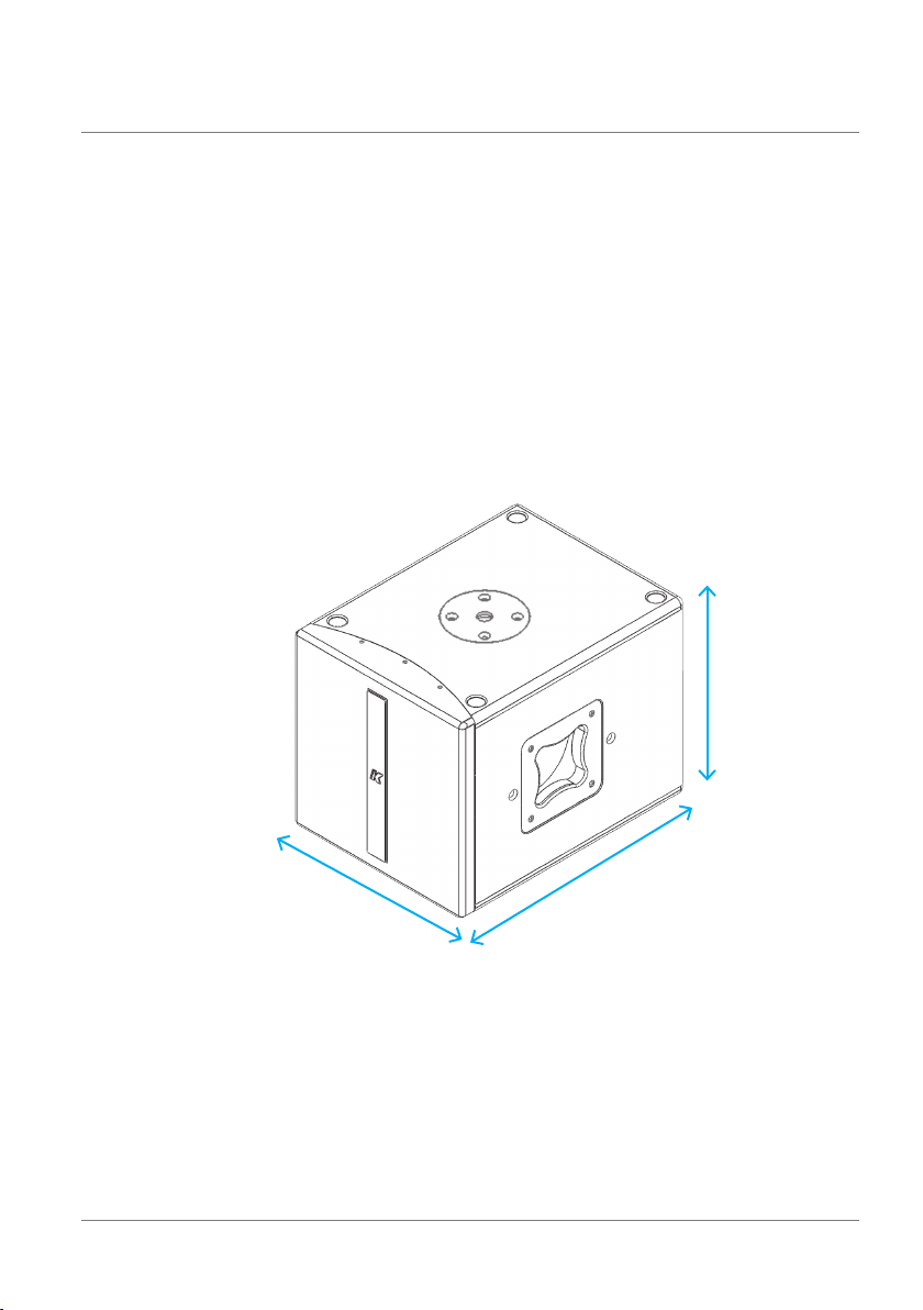
7. PHYSICAL
KMT12/KMT18
KMT12
33.5 cm
13.19”
REV. A
32.5 cm
12.91”
43.5 cm
17.13”
weight: 15.6 kg (34.39 lbs)
9
Page 10

KMT12/KMT18
KMT18
47.5 cm
18.70”
46.5 cm
18.31”
61 cm
24.02”
weight: 27.6 kg (60.85 lbs)
REV. A10
Page 11

8. AMPLIFIER
8.1 AC POWER CONNECTOR
The amplier module and any audio equipment connected to it (mixing consoles, processors, etc.) must be
properly connected to the AC power distribution, preserving AC line polarity. All grounding points should be
connected to a single node or common point, using the same cable gauge as the neutral and line cables. Bad
grounding connections within an audio system can produce noise, hum and/or serious damage to the input/
output stages in the system’s electronic equipment.
Before applying AC to any K-array self-powered speaker, be sure that the voltage
potential difference between neutral and earth ground is less than 5 VAC.
8.2 VOLTAGE REQUIREMENT
The KMT12 and KMT18’s switching power supply accommodates AC mains operating at either
115V or 230V. The KMT ampliers will continue to operate safely, without interruption, provided the
AC voltage remains within 90 - 135V or 190 - 250V (230V), at 50 or 60 Hz. Please verify that your
AC mains connection is capable of satisfying the power ratings for the device.
KMT12/KMT18
CAUTION
Do not connect the system to AC power mains exceeding 250V. Doing so will
cause signicant damage to the device and create serious risk for users!
8.3 CURRENT REQUIREMENT
The KMT12 and KMT18 present a dynamic load to the AC mains, drawing additional current as operating
levels increase. Different cables and circuit breakers heat up at varying rates, so it is essential to understand
current ratings and how they correspond to circuit breaker and cable specications. Maximum continuous
RMS current - measured over a period of at least ten seconds - is used to calculate the temperature increase
in cables, which drives the proper size and gauge cable and rating for slow-reacting thermal breakers. Maximum burst RMS current - measured over a period of approximately one second - is used to select the rating
for fast reacting magnetic breakers.
REV. A
11
Page 12

KMT12/KMT18
For best performance, voltage drops should not exceed 10% at 115V or 5% at 230V. The minimum electrical
service amperage required by a K-array loudspeakers system is the sum of their maximum continuous RMS
current. We recommend allowing an additional 30% above the minimum amperage to prevent peak voltage
drops at the service entry.
KMT12/KMT18 max continuous apparent power (VA)
410VA(>10 sec) - 2200VA (<1 sec)
8.4 REAR PANEL
14
20
1
6
4
2
5
9
15
19
3
7
16
8
10
11
12
17
13
18
19
REV. A12
Page 13

KMT12/KMT18
1) CH1 Line Inp ut. XLR lin e level input with +4 dBu s ensitiv ity.
2) C H2 Mic/ Line Inpu t. XLR input, with se lectab le sensit ivity fo r Mic (-30 dBu) or Line (+4 dBu).
3) C H1 Parallel Line Out. XLR paralle l output, p roviding a direct signal from t he CH1 Line Inp ut. This ou tput cann ot
be proc essed or c ontrolled via the K- Framewor k soft ware.
4) Phantom Powe r switch. Turns p hantom pow er (48V) on/off on CH1 and C H2 inputs.
5) Mic /Line sw itch. Sel ects CH2 input sens itivit y for Mic ( -3 0 dBu) or Line ( +4 dBu) level.
6) Li miting LE Ds. Indep endent LED s for the CH1 an d CH2 input s, which blink when the optica l limiter engages to
protect the corresponding preamp circuit. Limiter threshold is +5 dBu.
7) DSP O ut. Auxi liary X LR balanc ed output , contro lled via t he K-Frame work sof tware. Users can s elect th e signal
routed to this output and manage its amplitude and EQ individually.
8) D SP Out Power s witch. Turns phantom powe r (48V) on and off on the D SP out. Pha ntom power c an be engaged
to drive additional wireless signal transmitters/receivers.
9) A ES/EBU Digital In put. XLR in put connector for t wo-channel A ES/EBU di gital aud io, accepting samp le rates
from 32 k Hz – 96 kH z.
10) AES/ EBU Digi tal Outp ut. XLR out put, prov iding two-ch annel digital audio f rom AES/ EBU Input , at a sample r ate
of 48 kHz. T his outpu t cannot be p rocessed or cont rolled v ia the K-Fra mework so ftwar e.
11) REMOTE RS4 85 Link Inp ut. XLR input for con nectin g the KMT fr om anothe r RS485 d evice in a K- Framewor k
network. RS485 Link Inpu t can also be used to con nect a com puter run ning the K- Framewor k softw are (requires
K-USB USB-to-RS485 adapter).
12) REMOTE RS4 85 Link Ou tput. XLR output for c onnecting addit ional RS 485 devices in a K-Fra mework ne twork.
13) R EMOTE USB I nput. Con nects a computer running the K- Framewo rk soft ware, for remote control of the K MT.
Users c an manage a n entire net work of RS 485 devices with one PC connected vi a USB (see RS4 85 Network
diagram, below).
14) S peaker Out . Powered Sp eakon output, used to d rive pass ive speaker s, like a KP se ries mid -high mo dule or a
KMT series passive subwoofer
15) Power swit ch. Turns the KMT system on and off.
16) AC Inpu t. Powercon input for AC power. See p. 11 for voltage and powe r requirements.
17) AC Link. Powe rcon ouput for feedi ng AC mains po wer to addit ional K-array comp onents with a powerc on AC
input socket.
18) Extension Connector. Multi-pin connector for various K-array extension modules, for wireless control and audio
transm ission, memory extension, digit al signal encoding and audi o reproduction.
19) Power O n LED. Indic ates the sy stem is ON.
20) TOUCH SCREEN Co ntrol pan el. Provid es acces s to the main f unctio ns of the DSP o n board (see S ection 8 .5)
REV. A
RS485 XL R link
USB Conn ection fro m a PC
RS485 XL R link RS485 XL R link RS485 XL R link
RS48 5 networ k
13
Page 14

KMT12/KMT18
8.5 TOUCH SCREEN FUNCTIONS
HOME PAGE
INPUT PAGE
OUTPUT PAGE
ROUTING PAGES
The main functions of the onboard DSP can be
managed with the integrated touch screen. Functions
are grouped into six pages, shown as icons on the
Home page.
To reach the Home page from any other page,
touch the Home button.
The Input page allows users to independently manage
the amplitude of all the four input channels.
The Output page allows users to independently control
the amplitude of the signal routed to the Subwoofer, the
Speaker Output and the XLR DSP Output.
Three Routing pages allow users to manage the
routing of the four input channels to the three outputs
(Subwoofer, Speaker Out and XLR DSP Out) as well
independently set output volume and delay for each
output.
The delay values set in the Routing pages are summed
to the global delay assigned on the Delay page.
The arrow buttons on the top right corner of the screen
provide access to individual Routing pages for the
Subwoofer, Speaker Out and XLR DSP Out.
PRESET PAGES
INFO PAGE
Notes: The XLR DSP page does not provide control
over delay for this output.
Two Preset pages allow users to load presets stored
on-board. The arrow buttons on the top right corner
of the screen provide access to the Factory and User
preset pages. The arrows are also used to scroll
through, select and load one of the available presets.
The Info page contains information about the current
software and rmware, and the Logical ID of the KMT
module. The Logical ID is automatically assigned
to the KMT unit when connected to a K-Framework
network.
REV. A14
Page 15

DELAY PAGE
8.6 AUDIO INPUT CONNECTOR WIRING
KMT12/KMT18
The Delay page allows users to independently set
the delays for the speaker system (Subwoofer and
Speaker Out). This delay is summed with the delays
from the Routing pages of Subwoofer and Speaker
Out. The COARSE and FINE controls allow users to
change the delay in larger and smaller steps.
Notes: The delay control does not affect the XLR
DSP out. Delay for this output line can only be
managed through the K-Framework dedicated
controls.
The Audio section includes parallel LINK, which
allows users to distribute an audio signal to
multiple units. Up to 30 different modules can be
connected in parallel on the same balanced line
(with a source output impedance of 600 ohm).
CH 1 Line Input (female, balanced XLR) is
wired in parallel to CH1 Line Parallel Out (male,
balanced XLR). To create your own audio cables,
please use the following wiring diagrams:
8.7 AMPLIFICATION AND PROTECTION CIRCUITRY
The KMT12 and KMT18 are powered by a 2-channel digital amplier with 1,050 W output power per channel
(EIAJ test).
The KMT12 and KMT18’s amplier functions, including crossovers, equalization, phase response, and driver
protection, are controlled by an on-board DSP processor.
KMT series ampliers are equipped with several protection circuits to prevent damage. Two independent
audio limiters – Clip Limiter and Average Power Limiter – protect the internal circuitry against overload. A
Peak Current Shut Down protects the output stage with a tripping point at 35A. If tripped, Peak Current Shut
Down will reset after 2 seconds. A Temperature Protection Limiter also ensures the output stage stays below
a temperature of 85° C (approximate temperature of output power device).
INPUT PARALLEL
hot
2
1
3
cold
XLR connecto r
grd
grd
OUTPUT
1
3
cold
hot
2
REV. A
15
Page 16

KMT12/KMT18
9. K-Framework
9.1 SYSTEM REQUIREMENTS
SYSTEM REQUIREMENTS:
Operating Syste m: Windows X P / Vista / 7
CPU: Intel Pentium Dual Core
Memor y: 2 GB
REQUIRED COMPONENTS:
Microsoft .NET Framework 4:
http://www.microsoft.com/download/en/details.aspx?id=17718
Micro soft Vi sual C++ 2010 Redistri butable Package (x 86):
http://www.microsoft.com/download/en/details.aspx?id=5555
Micro soft Vi sual C++ 2010 Redistri butable Package (x 64):
http://www.microsoft.com/download/en/details.aspx?id=14632
9.2 INSTALLATION AND SET UP
To download your free K-Fr amework s oftwa re, please n avigate to t he K-array “ Soft ware Download” page locate d at
http://usa.k-array.com/en/download/software.html
Downlo ad the latest 32- or 6 4-bit install er. Decomp ress the .zip fil e and extract the “ K-Frame work.setup” installer fi le.
- Window s Vista and Windows 7 users can install the softw are by simply running t he K-Framework.set up file.
- Window s XP users a re required to instal l the nece ssary U SB driver s separately:
1) Open th e “Control Panel” m enu from th e “Star t Menu” or “My Comp uter.”
2) O pen “Device Manager ” from the Contr ol Panel and expand the “USB contr ollers” (or “Universal Serial Bus
controllers”) sub-menu.
3) R ight clic k on the upp er “K-A rray _Dsp01” object an d select “ Driver U pdate” to lau nch the “Hardware Update
Wizard”
REV. A16
Page 17

KMT12/KMT18
5
6
4) When asked t o allow th e online search, se lect “N ot now” a nd click “Next.”
5) Whe n asked for th e driver ’s location, selec t “Install from a list or specific location.”
6) In t he searc h and installation options window, selec t “Searc h for the best driver in t his location” and check the
“Incl ude this l ocatio n in the se arch” checkbox, t hen browse for the d river’s folder. The pa th should read:
C:\ProgramFiles\K-array\K-framework\drivers_rev02
Selec t the new dr iver fil e and click “Nex t.”
7) If warned about a failed “Win dows Logo” test, pl ease ignore and cl ick “Nex t”.
REV. A
8) T he first p art of dr iver insta llation i s now comp lete, and the “unknown” K-Array_Dsp01 por t has been u pdated
to read “ K-Array _Dsp01 A .” Click on “ Finish” an d repeat th e same procedure fo r the seco nd driver.
9) N ow you can se e that inside the Devic e Manage r Window both device s now have unique names (K- Array
_Ds p0 1 A an d K- Arr ay _D sp 01 B), a nd the ale rt sy mbo l is no lon ge r pr es ent . You ar e now 100 % re ady t o ge t st art ed !
17
Page 18

KMT12/KMT18
At star tup K-Fram ework will show the fo llowing w indow:
A5
A3
A2
A1
A4
img. A
A1) Connected D evices In dicator s hows the number of detected connected dev ices. N. B.: At star tup, the indicator
will sho w 0 devices, even if one or more units ar e connec ted. To detect al l connec ted devices, click the “Connect”
button (A2).
A2) Connect Button detects connected devices.
A3) Demo Butto n activate s the demo mo de of K-Fram ework. In t his mode, a ll device s that can be mangaed with the
K-Framework sof tware ap pear in the C onnected Device s Menu on th e left, so t hat the use r can navig ate through all
the dedi cated tabs and have a gli mpse of the di fferent functi ons availab le for each unit.
A4) K-array Device List d isplays all devices presently c onnected to the net work. N .B.: at st artu p the List w ill be
empt y, even if one or more uni ts are co nnect ed. To detec t all conn ected d evices, just click the “C onnect”
but ton (A 2).
A5) Acc ount Button opens t he Accou nt Settin gs Window w here user s can insert Us er Name and Password to a ccess
the K-A rray Community an d the share d preset dat abase.
A6) Zoom Button s zoom in (+) and out (-) of the w indow view.
A6
Click th e Connec t button to detect all p resentl y connec ted devic es.
All dete cted devices will ap pear in the K- Array D evice lis t, as shown i n Image B (be low):
REV. A18
Page 19

KMT12/KMT18
B1
B2
B3
img. B
B1) Connected Device Name.
B2) Device Menu Button sh ows and hid es the device menu.
B3) Device Menu d isplays th e basic info rmatio n about the d evice and t he shortcuts to open all available Editin g
Tab s.
9.3 USER TABS:
HOME
img. C
From the Home window, users can access the dedicated tabs, which follow the signal ow from input stage
to output stage.
REV. A
19
Page 20

KMT12/KMT18
INPUT TAB
Allows users to independently manage the EQ and gain of the four input channels.
D1
D2
D3
D4
D5
D6
D7
D8
img. D
D1) Frequency response display. Shows t he freque ncy respo nse cur ve resulti ng from th e filters set in the Inp ut EQ window
(below).
D2) Inpu t EQ window butt on. Opens the I nput EQ window, whe re users can se t three parame tric filter s for each inpu t channel.
D3) Inpu t Volume buttons. Adjusts the amplitude of th e input cha nnel
Input EQ wi ndow
D4) Input Volume disp lay. Shows the ga in or reduc tion cur rently ap plied to th e channel. Users ca n directly set the des ired
amount of g ain in the In put Volume display, instead of using the Input Volume bu ttons.
D5) Filter ty pe menu
D6) Filter frequency
D7) Filter Q
D8) Filte r boost
REV. A20
Page 21

KMT12/KMT18
ROUTING TAB
E1) Routing switch but ton. When lighted, the signal coming from the corresponding input on the lef t
column is routed to the corresponding output on the top row.
E1
img. E
DELAY TAB
Allows users to independently manage the delay applied to the three output channels.
F2F1 F3
REV. A
img. F
F1)
Global Delay buttons. Adjusts th e amount of ove rall d elay applied t o both the su bwoofer and sp eakon o utput
(which c an feed pas sive speake rs, i.e.: mid -high modules or a n additio nal subwoofer modules).
F2) Glo bal D elay disp lay. Sh ows the amo unt of dela y cur rent ly ap pli ed to t he ove rall syste m (sub woof er + sp eako n
output), b oth in milli second s and in meter s. Users c an directly write t he desire d amount of de lay in milli second s or
meters, instead of using the Global D elay buttons.
F3) Dedic ated Delays. Buttons and di splays in this section have exa ctly the sam e f unctions as t he ones in the
Overall delay section, but each set is dedicated exclusively to one output channel. From top to bottom: subwoofer
delay, speako n output de lay, and XLR DSP output delay.
21
Page 22

KMT12/KMT18
OUTPUT TAB
Allows users to independently manage the EQ, polarity, gain and limiting threshold of the three output channels.
G11
G6
G1
G3 G4 G5
G10G9G8G7
G2
img. G
G1) Frequency resp onse display. Show the frequency re sponse curve r esulting from t he filters set in the Input EQ w indow.
G2) Output EQ window button. Open the Output EQ window, where users can set up to six parametric filters for each
output channel.
G3) Phase button. Inverts the channel’s signal polarity (180° phase rotation).
G4) Outpu t Volume but tons. Adju sts the amp litude of ea ch output c hannel.
G5) Out put Volume di splay. Shows th e gain boost or reduc tion cur rently ap plied to eac h output c hannel. Us ers can
direct ly write t he desire d amount of volume insid e the Outp ut Volume disp lay, instead of using the Ou tput Volume buttons.
N.B.: T he XLR DS P section of the Outpu t tab does not provide th e management of any limiter for this ou tput.
Output EQ window
G6) Frequency response curve
G7) Filter type m enu
G8) Filter frequency
G9) F ilter boo st
G10) Filter Q
G11) Filter selec t button
REV. A22
Page 23

KMT12/KMT18
10. SERVICE
To obtain ser vice:
1) Contact t he offi cial K-ar ray distr ibutor in your count ry. Your local di stribut or will direct you to the appropr iate ser vice ce nter.
2) If you are calling for s ervic e, please h ave the seri al number (s) of the unit(s) availab le for refe rence. As k for Customer Service,
and be prepared to describe the problem clearly and completely.
3) If the pro blem cannot be resolved over the p hone, you may b e require d to send the u nit in for service. In this inst ance, you w ill
be provi ded with an R A (Return Authorization) number wh ich shoul d be included on al l shippin g documen ts and cor respondence
regarding the repair. Shipping charges are the responsibility of the purchaser.
Any atte mpt to modify or repl ace comp onents of t he device w ill invalidate your war ranty. Ser vice mu st be performed by an
author ized K-ar ray serv ice cent er.
Cleaning:
Use only a s oft, dr y cloth to c lean the housing. Do n ot use any sol vents, chemicals , or cleani ng soluti ons
conta ining alc ohol, amm onia, or ab rasives. D o not use any sp rays near th e produc t or allow liquids to spi ll
into any openings.
REV. A
23
Page 24

KMT12/KMT18
11. SPECIFICATIONS
Acoustics
Speak ers powe r
handling
Maximum power 1200 w
Impedance 8Ω
Frequency range 40Hz - 150 Hz +/- 3d B (preset d ependent)
SPL 1W/1mt 99 dB
Maximum SPL 128 dB continuous - 134 dB peak
Typ e DSP controlled
Frequency 150 Hz maximum (pres et dependent)
1 x 12” Neodymium speakers with 3 ”
Analog
Connectors
Connectors
2 male + 2 female 3-pin balanced XLR
Digital
1 male + 1 fem ale 3-pin XLR
Audio powered Output
Connector Female Speakon
Pin1+= CH1+ Pin1= CH1- Pin2+= N.C.
Wiring
(EAS)
700 w
1
2
Coverage
Omni
Crossover
Transducers
voice coil
Audio Input
Pin2= N.C.
KMT12
Remote control Input
Connectors 1 male + 1 fem ale XLR par allel
1 USB B Jack serial c onverte r
Power Input
Connectors 2 x PowerC on IN/OU T
Amplifiers
Typ e 1 module s class D - DS P contro lled
Subwoofer power 1000 Wat t
Speak er power
output
Protection
Operating range 90 - 125 Vac 60Hz / 190 - 240 Vac 50 Hz
Consumption 410 W
Minimum
operation voltage
Maximum
operation voltage
Max continuos
burst current
Dimensions
Dynami c limiter, over current, over temp,
135 Vac - 250 Vac
6A(>10 sec) - 12A (<1 sec) @ 230 V
and
10A(>10 sec) - 20A (<1sec) @ 115V
32.5 x 33 .5 x 43.5 cm
(12.91” x 13.19” x 17.13”)
Weight 15.6 kg (34.3 9 lbs)
3
@8Ω
3
1000 Wat t
@8Ω
short circuits
AC power
(Auto Switch)
85 Vac - 185 Vac
Physical
Notes for data
1. Maximum RMS applicabl e power fo r a musical signal, the refer ence signal is th e one prop osed by EI AJ
standard.
2. Meas ured @4 mt then scaled @1 mt
3. Amplifier wattage rating is based on the ma ximum unclipped b urst sine wave RMS voltage that t he
amplifier will produce into the nominal load impedance.
Ne w ma te ri al s an d de si gn are int ro du ce d in to exi st in g pr od uc ts wit ho ut pre vi ou s no ti ce . Pr es ent sys tems
may differ in some respects f rom thos e presented in this br ochure.
REV. A24
Page 25

KMT18
KMT12/KMT18
Acoustics
Speak ers powe r
handling
Maximum power 1400 w
Impedance 8Ω
Frequency range 30Hz - 150 Hz +/- 3dB (preset d ependen t)
SPL 1W/1mt 99 dB
Maximum SPL 130 dB cont inuous - 136 d B peak
800 w
(EAS)
1
2
Coverage
Omni
Crossover
Typ e DSP controlled
Frequency 150 Hz maximum (pres et dependent)
Transducers
1 x 18” Neodymium speakers with 3 ”
voice coil
Audio Input
Analog
Connectors
Connectors
2 male + 2 female 3-pin balanced XLR
Digital
1 male + 1 fem ale 3-pin XLR
Audio powered Output
Connector Female Speakon
Pin1+= CH1+ Pin1= CH1- Pin2+= N.C.
Wiring
Pin2= N.C.
Remote control Input
Connectors 1 male + 1 fem ale XLR par allel
1 USB B Jack serial c onverte r
Power Input
Connectors 2 x PowerC on IN/OU T
Amplifiers
Typ e 1 module s class D - DS P contro lled
Subwoofer power 1000 Wat t
Speak er power
output
Protection
Dynami c limiter, over current, over temp,
1000 Wat t
3
@8Ω
3
@8Ω
short circuits
AC power
Operating range 90 - 125 Vac 60Hz / 190 - 240 Vac 50 Hz
I. nom 410 W
Minimum
operation voltage
Maximum
operation voltage
Max continuos
and
burst current
10A(>10 sec) - 20A (<1sec) @ 115V
(Auto Switch)
85 Vac - 185 Vac
135 Vac - 250 Vac
6A(>10 sec) - 12A (<1 sec) @ 230 V
Physical
Dimensions
Weight 27.6 Kg (60.85 lbs)
46.5 x 47.5 x 61 cm
(18.31”x 18.70” x 24.0 2”)
REV. A
Notes for data
1. Maximum RMS applicabl e power fo r a musical signal, the refer ence signal is th e one prop osed by EI AJ
standard.
2. Meas ured @4 mt then scaled @1 mt
3. Amplifier wattage rating is based on the ma ximum unclipped b urst sine wave RMS voltage that t he
amplifier will produce into the nominal load impedance.
Ne w ma te ri al s an d de si gn are int ro du ce d in to exi st in g pr od uc ts wit ho ut pre vi ou s no ti ce . Pr es ent sys tems
may differ in some respects f rom thos e presented in this br ochure.
25
Page 26

KMT12/KMT18
12. DECLARATION OF CONFORMITY
Manufacturer/Importer: K-array srl unipersonale
Brand: K- ARRAY
Addres s: via Paolina Romagno li - 50037 S . Piero a Sieve Firenze ITALY
Date of Issue: 10 / 01 / 2012
Model C ode: KMT12 / KMT18
Declaration: Complies with essential protection requirements of Council Directive 89/336/EEC on
the approx imation of the L ows of the Membe r States relating to elect romagnetic compat ibility. Thi s
declaration applies to all specimens manufactured in accordance with the attached manufacturing
drawings which fo rm part o f this declaratio n. Assessment of complianc e of the prod uct with t he
requirements relating to electromagnetic compatibility was based on the following standards:
Safety : EN60 065 : 199 8
EMC:
EN55103-1 1997 Emissi on (1)
EN55103-2 1997 Immunity (2)
1) This devi ce may not cause harmful inter ferenc e
2) This device must accept any interference received including interference that may cause
undesidered operation
Marki ng :
Apply ing Year: 1998
Appli ed by: K-ar ray srl uni personale
Via Paolina Romagnoli
50037 S . Piero a Sieve
Firenze Italy
Tel. +39 055 8 48722 2
Fax +39 055 84872 38
Signed by: Franco Spataro - Technical Manager
REV. A26
Page 27

KMT12/KMT18
The contents of thi s manual are f urnished for in formational pur poses only. Hp Sound Equi pment s.r.l. as sumes no re sponsib ility
for any er rors or inacc uracies that m ay appear in this m anual. Hp Sound Eq uipment s.r.l. res erves the ri ght to make modif ications
without prior notice.
REV. A
27
Page 28

UMC031AA01ENA
K-array s.r.l. unipersonale
Via Paolina Romagnoli - 50037
San Piero a Sieve (Firenze) - Italy
tel. +39 055 8487222 - fax. +39 0558487238
e-mail: info@k-array.com
www.k-array.com
 Loading...