

Page 1
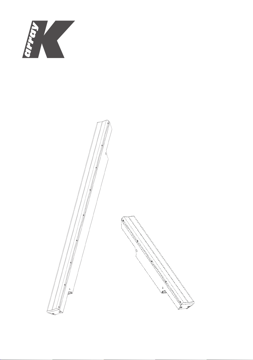
Kobra
KK52/KK102
USER’S MANUAL
English
Page 2

Page 3

Contents
SYMBOLS 5
1. INTRODUCTION 7
2. APPLICATIONS 7
3. KEY FEATURES 7
4. UNPACKING 8
5. WARRANTY 8
6. SAFETY 8
7. PHYSICAL 9
8. REAR PANEL 11
9. COVERAGE 12
10. WIRING 14
11. PROTECTION CIRCUITRY 14
12. ACCESSORIES AND CONFIGURATIONS 15
K-Fly2 16
K-Joint2 16
K-Wall2L 17
K-Wall2 17
K-KCluster2 / K-PCluster2 18
K-Foot2 18
K-KStage2 / K-PStage2 19
13. SERVICE 19
14. SPECIFICATIONS 20
K-Base2 15
KK52/KK102
REV. A
3
Page 4

KK52/KK102
REV. A4
Page 5
KK52/KK102
SYMBOLS
K-array declares that this device is in compliance with applicable CE standards and
regulations. Before putting the device into operation, please observe the respective
country-specic regulations!
WEEE
Please dispose of this product at the end of its operational lifetime by bringing it to your local
collection point or recycling center for such equipment.
This symbol, wherever it appears, alerts you to important operating and maintenance
instructions in the accompanying literature. Read the manual!
REV. A
Warning! Dangerous voltages: RISK of electric shock.
This symbol alerts the user to the presence of recommendations about the product’s use
and maintenance.
This device complies with Restriction of Hazardous Substances Directive.
5
Page 6

KK52/KK102
REV. A6
Page 7

KK52/KK102
1. INTRODUCTION
The K-array Kobras are passive speaker systems, comprised of 2 ” neodymium magnet transducers housed
in an elegant and sturdy stainless steel chassis. Available in t wo lengths, the KK52 features 8 drivers in a 0.5
m (19.7”), while the K K102 features 16 drivers a 1 m (39.4”) chassis. The ver tical dispersion pattern can be
switched for wide or narrow c overage, allowing for a great variety of applications. The Kobra’s closely spaced
cone drivers provide phase coherence, low distortion and focused listening both up close and at a distance.
To accommodate a range of applications, the vertical dispersion pattern c an be switched for either wide or
narrow coverage. Optional rigging and linking accessories allow multiple speakers to be interconnected,
creating a wide array of vertical and horizontal conf igurations for temporary or per manent installation.
For integration with other speakers or amplif ier s, the KK52 an d KK102 offer se lec table impedance (16Ω /6 4Ω
for the KK52 an d 8Ω /3 2Ω for t he K K102). Set to 64Ω up to ei ght KK52s can be powered via a singl e am plifier
channel, simplifying installation of wider distributed installed systems.
Kobras are able to reproduce the entire vocal frequency range with excellent intelligibility, star ting from 150 Hz.
Integrating powered subwoofers from K-array’s Redline series (KMT12, KMT18, KMT21) ensures excellent
coverage of the entire musical frequency range.
K-array ’s KA amplifier series also features custom presets, optimized for use with the Kobra series.
All Kobra components are designed by K-array and custom-made under K-array’s quality control system.
2. APPLICATIONS
• Theatres, Club, Churches
• Front ll and under-balcony ll
• Portable and installed AV systems
• Stage and AV studio monitoring
REV. A
3. KEY FEATURES
• Unique performance-to-size ratio
• Vertical, Horizontal and 3D line-array applications
• Multiple 2” long-excursion full-range cone drivers
• Wide horizontal coverage
• Electronically protected
• Selectable impedance (KK52: 16 / 64 Ω,
KK102: 8 / 32 Ω)
• Selectable vertical pattern (Spot / Flood)
• Weather proof, suitable for outdoor installations
• Available in black or white
7
Page 8
KK52/KK102
4. UNPACKING
Each K-a rray lou dspeaker is built to t he highe st standard and thoroughly inspec ted befo re leavin g the factory. Upo n arriva l,
carefully insp ect the shipping c arto n, then exa mine and te st your new l oudspe aker. If you fi nd any damag e, immediately
notif y the ship ping co mpany. Only t he consignee may institute a claim pr ocedure regarding the system’s elec tronic e quipme nt.
5. WARRANTY
K-array systems are warranted against manufacturing defects in materials or craftsmanship over a period of 2
years from the date of original purchase. During the warranty period K-array will, at its discretion, either repair or
replace products which prove to be defective provided that the product is returned in its original packaging, shipping
prepaid, to an authorized K-array service agent or distributor. K-array cannot be held responsible for defects caused
by unauthorized modications, improper use, negligence, exposure to inclement weather conditions, acts of God
or accidents, or any use of this product that is not in accordance with the instructions provided by K-array. K-array
is not liable for consequential damages. This warranty is exclusive and no other warranty is expressed or implied.
This warranty does not affect your statutory rights.
6. SAFETY
WARNING
• Only install the speaker in a location that can
structurally support the weight of the unit. Doing
otherwise may result in the unit falling down and
causing personal injury and property damage.
• Professional loudspeakers are capable of
producing extremely high sound levels and should
be used with care. Hearing loss is cumulative and
can result from extended exposure to levels in
excess of 90dB.
• Do not operate the speaker for an extended period
of time with the sound distorting.This is an indication
of malfunction, which can cause heat build-up and
result in a re.
• Never stand close to loudspeakers driven at high level.
• Suspending the system should only be done by
qualied personnel, following safe rigging practices.
Secure xings to the building structure are vital.
If there is any doubt, seek professional help from
architects, structural engineers or other specialists.
• No open ame sources, such as lighted candles,
should be placed near the device.
• Do not attempt to disassemble the unit. The unit
contains no user serviceable parts. Repairs should
be performed only by factory trained service
personnel.
REV. A8
Page 9

7. PHYSICAL
KK52/KK102
12 cm
4.72”
5.9 cm
2.32”
50 cm
19.7”
KK52
REV. A
8.1 cm
3.19”
weight: 2.3 kg (5.07 lbs)
9
Page 10

KK52/KK102
2.75 cm
1.08”
12 cm
4.72”
5.9 cm
2.32”
KK102
100 cm
39.4”
2.75 cm
1.08”
8.1 cm
3.19”
weight:
4.8 kg (10.58 lbs)
REV. A10
Page 11

8. REAR PANEL
KK52/KK102
REV. A
1 12
1) Mounti ng screw h oles. M ost K-ar ray mount ing or fl ying acc essor ies are d esigne d to screw i nto the spe akers
using th ese holes. The KK 52 is equip ped wit h two scr ew holes , while th e KK102 is equip ped with f our.
2) I mpedan ce switc h. Selects the im pedanc e of the speaker. Impedance must be set to hig h (64 Ω for K K52 and
32 Ω for KK102) when s peakers are drive n by KMT active modu les. Low im pedanc e may be use d when spe akers are
driven by m ost KA s eries a mplif iers (K A3, K A7, KA10). Please refer to your amplifier’s spec ific ations t o selec t the
correct speaker impedance for your configuration.
3
3) C overage s witch. S elects the vertical di spersion of the s peaker. Floo d coverage sets a wi de vert ical
diffusion an gle of 60° (KK52) / 35° (KK102). Flo od cover age is su ggeste d for sin gle speakers in di ffus ed (image 1)
shor t throw applicat ions, to o btain ma ximum di ffusion with a m inimum fo otpri nt. Spot c overage s ets a narr ower
verti cal dif fusi on angle of 10° (KK 52) / 7° (KK102). Sp ot coverage is recommended for long thr ow or mon itoring
applications (image 2). In most mul ti-speaker applicat ions, set coverag e to Spot (image 3). A c ombina tion of Fl ood
and Spot m ay also be ef fective for dow nfill ap plications (image 4).
11
Page 12

KK52/KK102
9. COVERAGE
Img1: Flood coverage
Img2: Spot coverage
REV. A12
Page 13

Img3: Array - spot cover age
KK52/KK102
REV. A
Img4: Array - D ownfill applic ation
13
Page 14

KK52/KK102
10. WIRING
Kobra KK52 and KK102 internal wiring is designed to pick up audio power signal from pins 1+ / 1- of a NL4
connector. 2+ and 2- pins, such as 1+ and 1-, are directly wired from one socket to the other, so signal can
pass through multiple KK modules without additional external cabling.
11. PROTECTION CIRCUITRY
Speakers are electrically protected from brief power overloads, within a reasonable range. Overloading the
speaker for extended periods of time can cause damage, so proper system design is strongly advised.
REV. A14
Page 15

KK52/KK102
12. ACCESSORIES AND CONFIGURATIONS
K-array offers a variety of dedicated accessories to mount and interconnect KK (Kobra) and KP (Python) series
speakers for a wide array of possible congurations.
K-Base2
Standing accessory for KK/KP speakers. For proper installation and operation, use with K-Foot2 and K-Joint2.
TIPS: where possible, screw the feet of K-Base2 to the ground.
REV. A
K-Foot2 K-Joint2
WARNING
Before connecting KK/KP series speakers to a K-Base 2, check the stability of the
ground where K-Base 2 is to be placed.
K-Base 2 should not be placed in a zone accessible to the audience.
Take maximum precaution in highly windy locations, especially when screwing the
K-Base2 to the ground is not possible.
15
Page 16

KK52/KK102
K-Fly2
Flying accessory set for KK/KP speakers.
For proper installation and operation, use with K-Joint2.
WARNING
Consult the dedicated product manual for
safety information and operation details.
K-Joint2
K-Joint2
Attachable joint to link a KK/KP speaker to most accessories
or to another KK/KP speaker with continuously variable
angle (-10° <.... > 10°).
REV. A16
Page 17

KK52/KK102
K-Wall2L
Wall / stand mounting accessory for KK/KP speakers with bi-dimensional tilting features.
K-Wall2L is designed to be screwed directly to the mounting screw holes of KK/KP speakers. When used with
KK102 it can be screwed to the internal or the external screw holes depending on the width of the desired angle.
K-Wall2
Wall mounting accessory for KK/KP speakers with full 3-dimensional tilting features.
K-Wall2 is designed to be screwed directly to the mounting screw holes of KK/KP speakers. When used with
KK102, the K-Wall2 can be screwed to either internal or external screw holes, depending on the width of the
desired angle.
REV. A
17
Page 18

KK52/KK102
K-KCluster2 / K-PCluster2
Wall mounting accessory for a horizontal cluster of three KK52/102 speakers.
K-KCluster 2 / K-PCluster 2 comes in a set of three different models: one with no angle between the three hanging
speakers, one with a 30° angle between speakers, one with a 60° angle between speakers.
0°
30°
60°
0°
30°
60°
K-Foot2
35 mm pole mounting accessory.
A 35 mm threaded pole is included for connecting additional K-array products such as KMT subwoofers or K-Base2.
REV. A18
Page 19

KK52/KK102
K-KStage2 / K-PStage2
Ground laying accessories for KK/KP series speakers.
K-KStage 2 / K-PStage 2 allow users to safely lay KK / KP series speakers on the ground with three different
angles: 0°, 30° and 45°. Ideal applications are monitoring and front-ll.
13. SERVICE
To obtain service:
1) Contact the ofcial K-array distributor in your country. Your local distributor will direct you to the appropriate
service center.
2) If you are calling for service, please have the serial number(s) of the unit(s) available for reference. Ask for Cus-
tomer Service, and be prepared to describe the problem clearly and completely.
3) If the problem cannot be resolved over the phone, you may be required to send the unit in for service. In this
instance, you will be provided with an RA (Return Authorization) number which should be included on all shipping
documents and correspondence regarding the repair. Shipping charges are the responsibility of the purchaser.
Any attempt to modify or replace components of the device will invalidate your warranty. Service must be performed by an authorized K-array service center.
Cleaning:
Use only a soft, dry clot h to clean the hous ing. Do not use any solvents, ch emicals, or cle aning solutions
conta ining alc ohol, a mmonia , or abras ives. Do no t use any spr ays near th e produc t or allow l iquids to spill
into any openings.
REV. A
19
Page 20

KK52/KK102
14. SPECIFICATIONS
Speakers power handling 200 W
Frequency range 150 Hz - 20 KHz .
KK52
Acoustics
(AES)
Max po wer 400 W
Impedance 16Ω or 64Ω (select able)
SPL 1W / 1mt 95 dB
Maximum SPL 118 dB continuo us - 124 dB peak
Horizontal 110 °
Vert ica l 10°- 60° (selectable)
Typ e External Crossover required
Frequency High pass @150 Hz, 24 d B/oct su ggeste d minimu m
Transducers
Full range 8 x 2” Neo dymium magnet wit h 0.75” voice coil
Power Audio Input
Connectors 2 x 4-pin Speakon
Wiring 1+ 1-
(signal IN & LI NK); 2+ 2- (through)
Selection Switch
Vertical pattern Spoot - Fl ood
Impedance 16 Ω - 64Ω
Dimensions 8.1 x 50 x 5.9 cm (3.19” x 19.7” x 2.32”)
Weight 2.3 kg (5.07 lbs)
1. Maximum R MS appli cable pow er for a musi cal signa l, the
referenc e signal is the one pr oposed by EI AJ standard.
2. Measur ed @4 mt then scaled @1 mt
New mater ials and de sign are int roduce d into existi ng
produc ts without previ ous notice. Pre sent systems may dif fer
in some res pects from those p resented in this br ochure.
1
2
Coverage
Crossover
Physical
REV. A20
Page 21

KK102
Acoustics
Speakers power handling 400 W
Max po wer 800 W
Impedance 8Ω or 32Ω (selectable)
Frequency range 150 Hz - 20 KHz .
SPL 1W / 1mt 98 dB
Maximum SPL 124 dB conti nuous - 130 d B peak
Coverage
Horizontal 110 °
Vert ica l 7°- 35° (selectable)
Crossover
Typ e External Crossover required
Frequency High pas s @150 Hz, 24 dB/oct suggested minimum
Transducers
Full range 16 x 2” Neodymium ma gnet wit h 0.75” voice c oil
Power Audio Input
Connectors 2 x 4- pin Spe akon
Wiring 1+ 1-
Vertical pattern Sp oot - Floo d
Impedance 8Ω - 32Ω
Dimensions 8.1 x 100 x 5.9 cm (3.19” x 39. 4” x 2.32 ”)
Weight 4,8 Kg (10.58 lbs)
1. Maximum R MS appli cable pow er for a musi cal signa l, the
2. Measur ed @4 mt then scale d @1 mt
(signal IN & LI NK); 2+ 2- (through)
Selection Switch
Physical
referenc e signal is th e one propo sed by EIAJ stan dard.
New materials and design are introduced into existing
products without previous notice. Present systems may differ
in some res pects from thos e presented in this b rochure.
KK52/KK102
(AES)
1
2
REV. A
21
Page 22

KK52/KK102
REV. A22
Page 23

KK52/KK102
The contents of th is manual a re furn ished fo r inform ationa l purpo ses only. Hp Sound Equipment s.r.l. as sumes no r espons ibilit y
for any er rors or inacc uracies that m ay appear in this m anual. Hp Sound Eq uipment s.r.l. res erves the ri ght to make modif ications
without prior notice.
REV. A
23
Page 24

UMC029AA01ENA
K-array s.r.l. unipersonale
Via Paolina Romagnoli - 50037
San Piero a Sieve (Firenze) - Italy
tel. +39 055 8487222 - fax. +39 0558487238
e-mail: info@k-array.com
www.k-array.com
 Loading...