

1
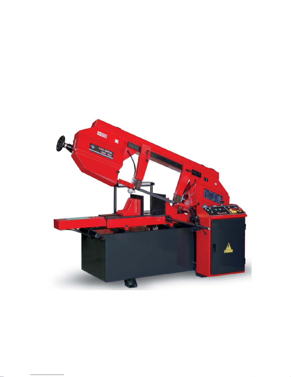
KMT 400 KSA
OPERATION MANUAL

2
MACHINE CERTIFICATION AND IDENTIFICATION
MARKING
NOTE : This manual is a part of the machine and must accompany it if
moved within the company or sold.
ATTENTION!!
BEFORE USING THE MACHINE, PLEASE READ THIS
MANUAL CAREFULLY. ALL EXPLANATIONS,
INSTRUCTIONS AND WARNINGS ARE INTENDED TO
PROTECT YOU!

3
EC DECLARATION OF CONFORMITY
The manufacturer declares that the machinery described herein
conforms to the following EC directives and harmonised standards
and relevant essential health and safety requirements.
Manufacturer: KARMETAL SAN. & TIC. LTD. STI
Address: D–100 Karayolu Uzeri Ayvalik Mevkii Hanli Adapazari / TURKEY
Phone: +90 264 276 59 16 (3 lines)
Fax: +90 264 276 59 19
Web: www.karmetal.com.tr
E-mail: info@karmetal.com.tr
Machine type/model: KMT 400 KDG Semi Automatic Miter Bandsaw Machine
Applicable EC Directives:
Machinery Directive 2006/42/EC,
Low Voltage Directive (LVD) 2006/95/EC and
Electromagnetic Compatibility (EMC) Directive 2004/108/EC
Applicable Harmonized Standards:
TS EN ISO 12100–1 (2007), TS EN ISO 12100–2 (2006), TS EN ISO 13850 (2007),
TS EN 953 (1998), TS EN ISO 13849–1 (2007), TS EN 1088 (2005), TS EN ISO 60204–1 (2008)
Name : Fatih KAR
Position : Factory Manager
Signature :
Place-Date : SAKARYA / 25.03.2010

4
WARRANTY CONDITIONS
The machine is under the warranty of KARMETAL LTD. ŞTİ. For mechanical parts a period
of 2 years for electric and electronic arts a period of 1 year from the date of purchase. This
warranty is subject to all of the terms and conditions listed below:
1. This warranty is valid only if the Warranty Registration Form is filled in and returned
to the manufacturer or its authorized dealer within two months after the date of
purchase.
2. The obligation of the manufacturer under this warranty shall be limited to repairing or
replacing components which proves defective and which our examination shall
disclose to our satisfaction to be defective.
3. Defects due to improper operation, misuse, neglect, alteration, irregular voltage
conditions, inadequate wiring, improper installation (all electrical and electronic
components, all electrical motors etc.) and due to accidents or any damage caused
by transportation, flood, fire, natural disasters, theft are not included in this warranty
and are strictly the responsibility of the purchaser.
4. Any part returned to KARMETAL or its authorized dealer under the terms of this
warranty shall be on the basis of transportation charges prepaid by the customer and
must be accompanied by a record of the machine model code and serial number.
5. This warranty does not apply to the following components; band saw blade, blade
pressure pads or brackets and blade guide bearings because of being
consumables.
6. Manufacturer and authorized dealer cannot be blamed within maximum repair period
for the material or moral damage. Apart from that act the period as Warranty
Conditions and there will not be done any retroactive requirement.
KARMETAL SAN. & TIC. LTD. STI.
Dealer:

5
Important!
This form must be duly completed and returned to the manufacturer or its authorized dealer
within two months after the date of purchase. Failure to do so will void the warranty.
WARRANTY REGISTRATION FORM
Machine Model : …………………………………………………………
Serial Number : …………………………………………………………
Invoice Date : …………………………………………………………
Invoice Number : …………………………………………………………
Dealer:
…………………………
Customer:
…………………………

6
Contents:
MACHINE CERTIFICATION AND IDENTIFICATION MARKING ............................ 2
ATTENTION!! ......................................................................................................................... 2
EC DECLARATION OF CONFORMITY............................................................................ 3
WARRANTY CONDITIONS ................................................................................................. 4
WARRANTY REGISTRATION FORM............................................................................... 5
BAND SAW USING INSTRUCTIONS ................ ERROR! BOOKMARK NOT DEFINED.
CHAPTER 1: SAFETY ......................................................................................................... 8
1. SAFETY RULES ....................................................................................................................... 8
2. DANGER ZONES ON THE MACHINE ....................................................................................... 9
3. SAFETY EQUIPMENTS AND ASSIGNMENTS .......................................................................... 10
4. WARNING LABELS AND ASSIGNMENTS ............................................................................... 12
CHAPTER II : DESCRIPTION AND PROPERTIES ............................................... 13
1. TECHNICAL PROPERTIES OF THE MACHINE ....................................................................... 13
2. STANDART EQUIPMENT ....................................................................................................... 13
3. OPTIONAL EQUIPMENT ........................................................................................................ 13
4. NOISE LEVEL ........................................................................................................................ 13
5. MACHINE DIMENSIONS ........................................................................................................ 14
6. PROPERTIES TABLE ACCORDING TO METAL SAWDUST .................................................... 14
7. KMT 350 KSA BAND SAW MACHINE CUTTING CAPACITY ............................................... 15
CHAPTER III : TRANSPORTATION AND INSTALLATION ................................. 16
1. HANDLING THE UNPACKED MACHINE ................................................................................. 16
2. AFTER UNPACKING THE MACHINE ...................................................................................... 16
3. ENVIRONMENTAL CONDITIONS ........................................................................................... 16
4. SHIPPING BRACE .................................................................................................................. 17
5. MACHINE PLACEMENT AND POSITION ................................................................................ 17
CHAPTER IV : PREPARATION BEFORE OPERATION ..................................... 18
1- CLEANING ......................................................................................................................... 18
2- REMOVING THE SHIPPING BRACE .................................................................................... 18
3- LUBRICATING .................................................................................................................... 18
4- HYDRAULIC ....................................................................................................................... 18
5- COOLANT .......................................................................................................................... 18

7
CHAPTER V: OPERATION ............................................................................................ 20
1- CONTROL PANEL .............................................................................................................. 20
2- BLADE CHANGING PROCEDURE ....................................................................................... 21
CHAPTER VI: MAINTENANCE ..................................................................................... 24
1- DAILY MAINTENANCE............................................................................................... 24
2- WEEKLY MAINTENANCE ......................................................................................... 24
3- MONTHLY MAINTENANCE ...................................................................................... 24
4- SIX-MONTHLY MAINTENANCE .............................................................................. 24
5- PERIODIC MAINTENANCE ....................................................................................... 24
CHAPTER VII: TROUBLESHOOTING ........................................................................ 25
CHAPTER VIII: DISMANTLING ................................................................................... 26
CHAPTER IX: MACHINE FUNCTIONAL PARTS ....................................................... 27
1. CUPBOARD GROUP ........................................................................................................ 28
2. VISE UNDERTRAY GROUP ........................................................................................... 29
3. JOINT FRAME GROUP ................................................................................................... 30
4. MOTION WITH HYDRAULIC VISE ............................................................................. 31
5. VISE GROUP...................................................................................................................... 32
6. GEARBOX GROUP ........................................................................................................... 35
7. HYDROMECHANIC BAND STRETCHING GROUP .................................................. 36
8. HYDRAULIC GROUP ...................................................................................................... 37
9. COOLANT GROUP ........................................................................................................... 40
10. BANDSAW GUIDE GROUP........................................................................................... 41
11. ELECTRICITY GROUP ................................................................................................. 42
12.SPRING GROUP............................................................................................................... 49
13.BAND TENSION GROUP................................................................................................ 50
ASSEMBLY OF INFEED TABLE ....................................................................................... 51

8
CHAPTER 1: SAFETY
1. Safety Rules
• Never allow unqualified persons to operate or interfere with the machine.
• It is important to develop personal safety awareness. Observe all related safety regulations and
pay attention for hazardous conditions. Discuss these conditions with your supervisor.
• You must use personal protective equipment, like safety glasses, gloves, safety work shoes.
• Do not remove warning signs and/or instruction plates off the machine.
• Do not open/remove any door or guard during operation.
• Make sure that all machine controls are set for the desired mode of operation, whenever the
setting of the machine control is changed, run the machine in slow mode to make sure it
operates as expected.
• Never disable any safety device to avoid its assigned function. These devices are intended to
protect both the machine and its operator.
• Do not load, unload, operate or adjust the machine without proper instructions.
• This machine is specifically designed for cutting general metal material. Do not cut wood and
analogous material, meat, fishery, food and agriculture products, combustible and radioactive
materials.
• Enough space should be provided around the machine to avoid hitting and provide a convenient
operation.
• Do not leave any tool on the machine after use. Do not put work stock or tools around the
machine, to avoid injury.
• Do not operate the machine with its safety guards removed.
• Do not wear gloves when operating through control panel.
• Wear gloves only when loading/unloading the material, changing the blade and chip brush.
• Never touch the blade, moving work stock, nor put your hands into the vise area or chip
conveyor unit until the machine halts completely.
• When selecting blade, blade speed and coolant, please refer to the operation manual or related
documents.
• Before installation and operate the machine check the sufficiency of the earth of the machine
to your electrician. Do not operate the machine without the earth.
• Determined and declared bench life of the machine by the Ministry of Industry and Trade is
10 years.
• For longevity please follow the maintenance directions at the manual.
• For productive usage of energy and saw blade, use the recommended saw blade by the PLC.

9
2. Danger Zones on the Machine
10
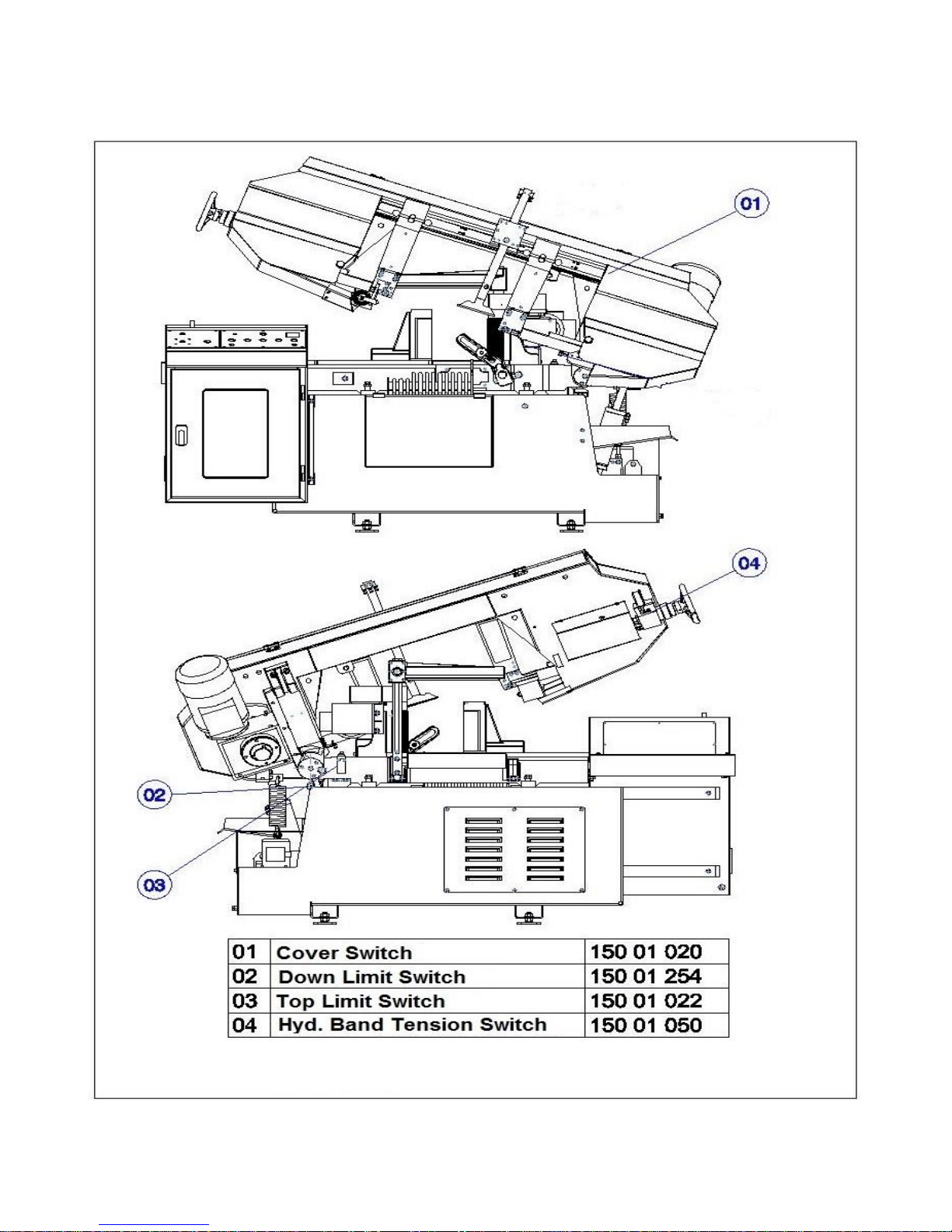
3. Safety Equipments and Assignments

11
3.1. Cover Switch
This switch provides to shut down the machine while the bow cover is open. Running the
machine may cause wounding and serious gashes. Machine gives aural warning while the
cover is open.
3.2. Down Limit Switch
This switch is used to adjust the bow’s nadir to goes down. Down limit switch is a factory
setting. Please do not tinker with the down limit switch.
3.3. Top Limit Switch
Top limit switch is an adjustable switch and is used to adjust the bow’s apex to go rises up.
3.4. Hydraulic Band Tension Switch
This switch is used for to stop the machine while the blade pressure gets smaller than adjusted
ones. The main causes of decrease in pressure are; dulling, cracking or breaking of blade.
Operating the machine under these conditions endanger the operator.
3.5. Electricity Panel Cover Switch
This switch is used to stop the machine while the cover is open. Operating the machine may
causes to electric shocks while the electricity panel cover is open. Machine gives aural
warning while the cover is open.
3.6. Emergency Stop Button
Emergency stop button, places on the operator control panel- near the
main switch, is red button and you can see it easily. In emergency
cases, press to this button to stop the machine. Machine does not run while the button is
pressed. To rerun the machine, please turn left and release the button.
MAIN
SWITCH
EMERGENCY

12
4. Warning Labels and Assignments
4.1. Glove Label
Please use personal protective equipment, like glove, during operation and
while changing the blade.
4.2. Electricity Neutral Warning Label
In this label, we declared the instructions how to make the electric connection before
installing machine or after handling the machine.
4.3. High Voltage Label
This label shows high voltage risk parts. All electrical connections should
be done by a qualified electrician.
4.4. Safety Equipments Label
All the safety devices and guards are designed to intend to
protect the operator. Please do not remove these safety
guards.
4.5. Arrow Label
Blade’s direction of rotation belongs to machine type. Arrow label
on the machine shows blade’s direction of rotation. Please pay
attention on direction of rotation while changing blade.

13
CHAPTER II: DESCRIPTION AND PROPERTIES
1. Technical Properties of the Machine
MAIN MOTOR
4 kW, 1400 rpm
HYDRAULIC MOTOR
0,37 kW, 1400 rpm
COOLANT PUMP
0,09 kW, 2800 rpm
CUTTING SPEED
25-90 m/min
BLADE DIMENSIONS
4650x34x1,1
BLADE TENSION
Min. 30 bar -Max. 50 bar
BLADE QUALITY
Bi Metal
WORK STOCK DRIVE MECHANIZM
Infinite
HEIGHT OF VISE BED
750 mm
WEIGHT
1350 Kg.
MACHINE DIMENSIONS
1400x2200x1200 mm
VOLTAGE
460 VAC
NUMBER OF PHASE
3 ~
FREQUENCY
60 Hz
2. Standard Equipment
Hydraulic Vise
Inverter
Hydromechanic Band Tension
Material Feeding Table with Rolls
1 Bandsaw Blade
3. Optional Equipment
Laser Line
Bundle Cutting Table
Chip Conveyor
Hydraulic Top Pressure
4. Noise Level
In accordance with the Machinery Directive 2006/42/EC
• The A-weighted continuous acoustic pressure does not exceed 70 dB (A).
• The maximum level of the C-weighted instantaneous acoustic pressure is always less than 130 dB.
NOTE: With the machine operating, the noise level will vary according to the different materials being
processed and setting up.The user must therefore assess the intensity and if necessary provide the operators with
the necessary personal protection.
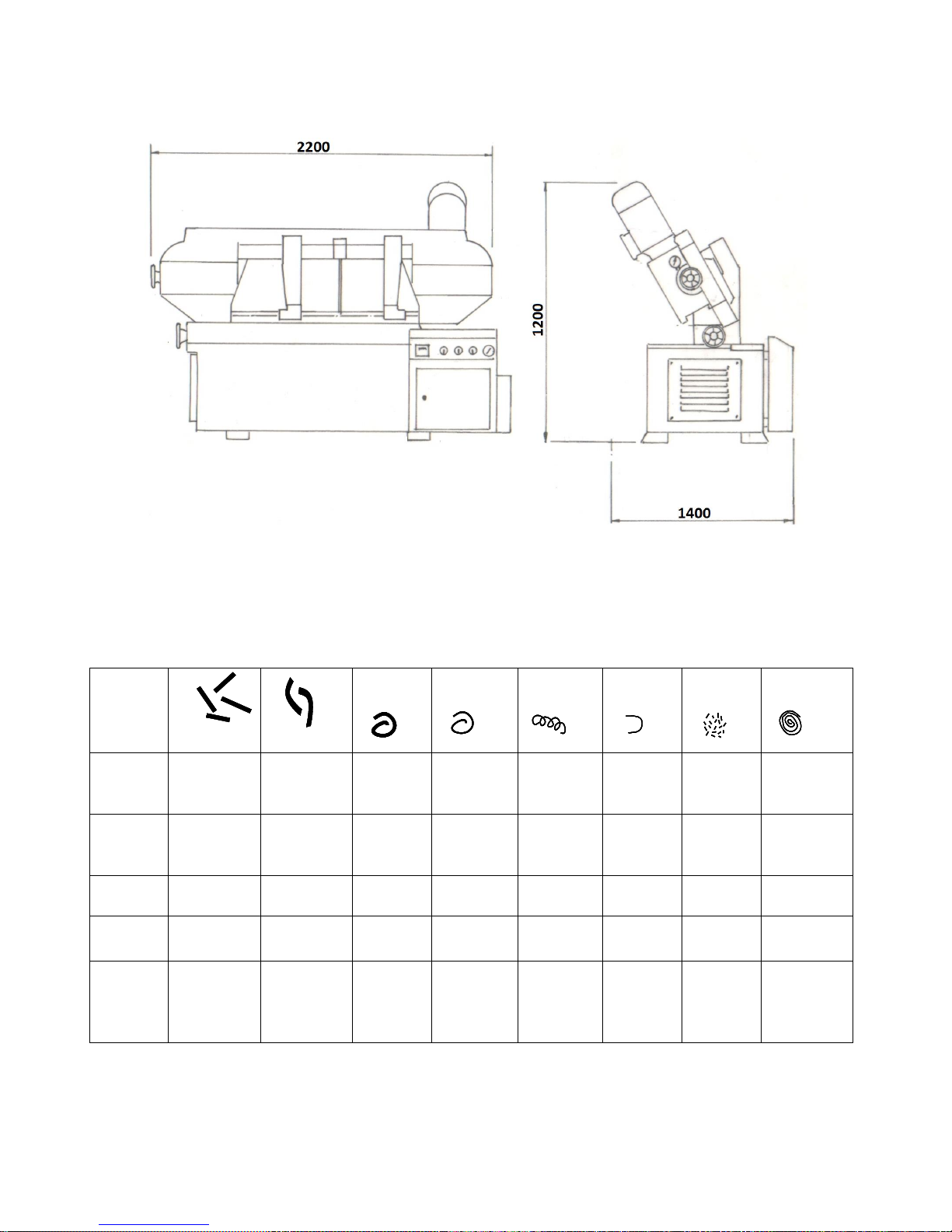
14
5. Machine Dimensions
6. Properties Table According to Metal Sawdust
Filing
Shape of
the
sawdust
Thick, hard
and short
Thick, hard
and brittle
Thick,
hard and
curled
Thick,
hard and
curled
Thin,
spiral and
curled
Thin,
spiral and
curled
Like dust
Thin and
very curled
Color of
the
sawdust
Blue or
brown
Blue or
brown
Silver or
yellow
Silver
Silver
Silver
Silver
Silver
Band saw
speed
Decrease
Decrease
Suitable
Increase
Suitable
Suitable
Decrease
Suitable
Advance
speed
Decrease
Decrease
Decrease
a little
Decrease
Suitable
Increase
Increase
Decrease
The
others
Control
lubricant
coolant
level
Control
lubricant
coolant
level
Control
number
of teeth
Control
number of
teeth
Use thick
pitch saw

15
7. KMT 350 KSA Band saw Machine Cutting Capacity
MATERIALS
DIN NORM
MATERIAL DIA. (mm)
BANDSAW
SPEED m/min.
LUBRICANT
COOLANT
0-30
30-50
50-80
80-120
120-200
200-
400
NUMBER OF TEETH
EMILSION
COOLING
OIL
YES
NO
STRUCTURAL
STEEL
ST 37-60
10 N
8 N
6 N
4 H
3 H
2 H
50-70
1:10
X
CASE-
HARDENING
STEEL
14 Nİ Cr 14
21 Nİ Cr MO2
10 N
8 N
6 N
4 H
3 H
2 H
50-60
1:10
X
FREE-
CUTTING-
STEEL
45 S 20
10 N
6 N
4 H
3 H
2 H
2 H
80-120
1:10
X
HEAT
TREATABLE
STEEL
Ck 35 –Ck 45
42 Cr Mo
10 N
8 N
6 H
4 H
3 H
2 H
60-70
1:20
X
BEARING
STEEL
100 Cr Mn 6
10 N
8 N
6 N
4 H
3 H
2 H
35-50
1:30
X
SPRING STEEL
60 Si 7
10 N
8 N
6 N
4 H
3 H
2 H
45-60
1:30
X
TOOL STEEL
ALLOYED
X 42 Cr 13
56 Ni Cr Mo V7
45 W Cr V 7
10 N
8 N
6 N
4 H
3 H
2 H
35-50
1:30
X
HIGH SPEED
STEEL
S 6-5-2-5
S-3-2-3
10 N
8 N
6 N
4 N
3 H
2 H
35-45
1:30
X
VALVE STEEL
X 45 Cr Ni W
18 9
10 N
8 N
6 H
3 H
2 H
2 H
30-45
1:20
X
CAST STEEL
GN-38
10 N
8 N
6 N
4 N
3 H
2 N
30-40
1:50
X
CAST IRON
GG 30
10 N
8 N
6 N
4 N
3 H
2 H
30-60
......
X
COPPER
KE-Cu
10 N
6 N
4 H
3 H
2 H
1.25 H
100-400
1:10
X
BRASS
Cu Zn 10
8 N
6 N
4 H
3 H
2 H
1.25 H
80-200
1:50
X
BRONZE
Cu Sn 6
10 N
6 N
4 H
3 H
2 H
1.25 H
80-150
1:30
X
ALUMINIUM
AL-CAST-
ALLOYS
Al Mg Si Pb
10 N
6N
4 H
3 H
2 H
1.25 H
80-800
1:10
X
THERMOPLAS
TICS
PVC
TEFLON
6 N
4 H
3 H
3 H
2 H
1.25 H
100-400
1:50
X
0 °
400 mm
400 mm
400 x 450 mm

16
CHAPTER III: TRANSPORTATION AND INSTALLATION
1. Handling the Unpacked Machine
Make sure the machine is safely loaded and balanced when moving it with a forklift, failing to
do so may cause personal injury or damage to the machine
2. After Unpacking the Machine
Put the machine in a dry and sheltered place to prevent damage to the electrical and mechanical
components. Apply appropriate lubricant (machine oil or grease) on the slide ways and nonpainted areas to prevent rust.
3. Environmental Conditions
• Mains voltage and frequency complying with the machine motor characteristics.
• Environment temperature from -10° C to 50° C.
• Relative humidity is %5 to %90.
 Loading...