

Page 1

KARI Float Switch
Operation
Manual
3H 3L 3Y 3A 3HE 3LE 3YE 3AE
High level alarm
Issued when the level of liquid
gets too high, or initiates valve
discharging when, for example,
the pump is out of order.
3
Start
Large amount of liquid.
Discharging pump starts.
Stop
Lower limit for discharging.
Discharging pump stops.
Image 3H shows the operation
of the KARI Float Switch
Page 2

KARI Float Switch
– compact and reliable
The KARI Float Switch is a control device for charging and discharging pumps
and motor and magnetic valves. It is also an alarm device that alerts the
user at specied surface levels. Thanks to its large oat casing (Ø 170 mm),
the KARI Float Switch has a buoyancy that guarantees smooth, troublefree operation under all conditions. SGS FIMKO Oy (the Finnish Electrical
Inspectorate) has performed testing in accordance with the Low Voltage
Directive (LVD) and approved the KARI Float Switch for use in non-ammable
liquids at 250 volts.
FUNCTIONS
DISCHARGING-PUMP CONTROL CHARGING-PUMP CONTROL
Discharging-pump control + high level alarm.
3H
Pump control with one switching element.
Discharging-pump control + isolated high
level alarm. Pump control with one switching
3HE
element.
Discharging-pump control + high level alarm
3Y
Pump control with two switching elements.
Discharging-pump control + isolated high
level alarm. Pump control with two switching
3YE
elements.
ORDER CODE
3HE
K N Au
Gold-plated contacts (Au)
1 mA ... 100 mA
Heat-resistant cable types
N = TPU
S = silicone
T = teon
U = UL/CSA PVC
Cable types
Empty = PVC
A = rubber
N = TPU
S = silicone
T = teon
U = UL/CSA PVC
K = heat-resistant
Circuit diagram
3H, 3L, 3Y, 3A, 3HE, 3LE, 3YE, 3AE
Deviating
surface levels (cm)
Dxx-xx
Special type ID
Vxx
Charging-pump control + low level alarm.
3L
Pump control with one switching element.
Charging-pump control + isolated low level
alarm. Pump control with one switching
3LE
element.
Charging-pump control + low level alarm.
3A
Pump control with two switching elements.
Charging-pump control + isolated low level
alarm. Pump control with two switching
3AE
elements.
_KP
_20
Cable
length
(m)
1st letter
Non-standard cable weight
K = 700 g
L = 1000 g
2nd letter
P = pressure-resistant
3H | 3L | 3Y | 3A | 3HE | 3LE | 3YE | 3AE
Page 3
INSTALLATION AND
ADJUSTMENT
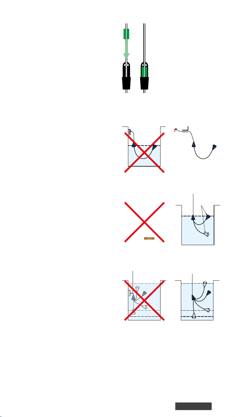
The KARI Float Switch is mounted
to hang from its own cable. The oat
switch oats on the surface of the liquid
and follows the movement of the liquid’s
surface. Functions are controlled in
the various tilt angles of the oat. The
switching distance differential is adjusted
by moving the weight along the cable.
Installation considerations
• The height at which the oat hangs
and the distance of the cable weight
from the oat can be adjusted. The
differential between the start and stop
levels is at its lowest when the cable
weight is about 10 cm from the tip of
the oat’s strain-relief (see page 7).
• If the viscosity of the liquid is high
or oating to the sides needs to be
restricted, we recommend a heavier
weight of cable, which we supply as
required. The weights are xed to the
cable with a clamp wedge (see Image 1).
• It is important to keep the junction
box in a dry environment. If this is not
possible, the ends of oat switch cables
must be covered with, for example,
protective grease (see Images 2 and 3).
An IP68 junction box is also available.
• The oat switch needs a cable weight
or other anchor point to operate.
• The installation site must be selected
such that the oat cannot become
caught under or stay on top of any
surface or get entangled in other
structures (see Image 4).
• When the oat switch is tested without
being oated, its correct orientation
must be considered: the ‘UP’ mark on
the side of the bottom portion must
face upward. For example, when placed
on the oor on its side, the oat switch
settles into this position because of its
internal keel weight (see Image 5).
• Tying the oat switch from its cable
near the oat to, for example, the
ascension pipe of the pump decreases
the useful life of the cable; the oat
switch should hang freely from its cable
(as shown in Image 6).
A) B)
Image 1. Cable weights and the hanging loop are
xed to the cable with a clamp wedge (A–B).
Image 2. Avoid extending or
connecting the cable in humid
conditions.
Image 4. Take care to ensure
the free movement of the
oat.
Image 6. Avoid xing the oat such that
a sharp corner can cause kinks or wear to the cable.
Image 3.
Up!
Image 5. Note the correct
orientation of the oat.
i
Page 4
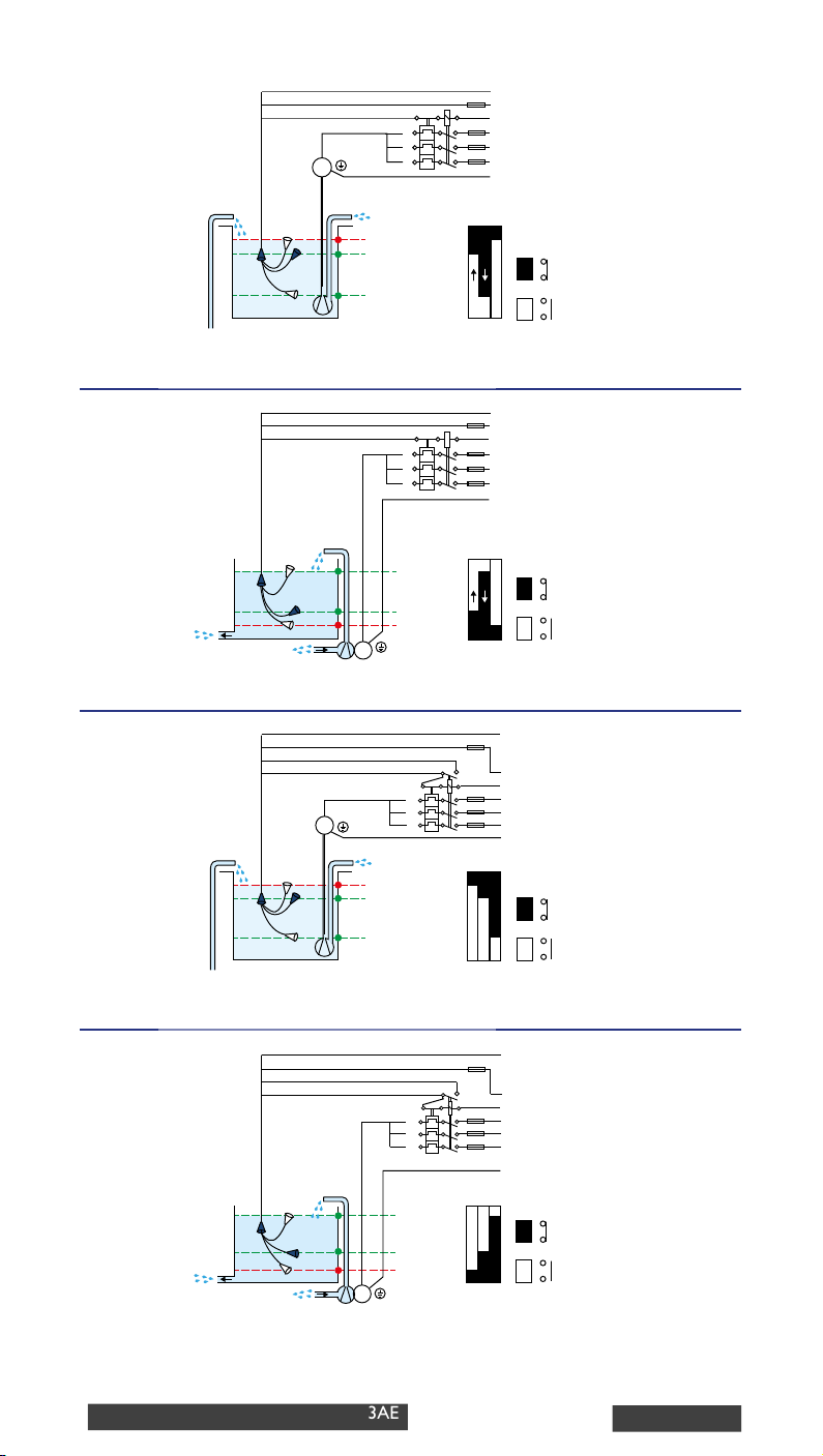
CIRCUIT DIAGRAM
3
3H
1
2
U
V
Alarm
Start
W
M
Stop
DISCHARGING-PUMP CONTROL + HIGH LEVEL ALARM
Pump control with one switching element.
High level alarm
6...250 V
L1
L2
L3
PE
1-2
1-3
Circuit
closed
Circuit
open
3L
3
1
2
U
V
W
Stop
Start
Alarm
Low level alarm
6...250 V
L1
L2
L3
PE
1-2
1-3
Circuit
closed
Circuit
open
M
CHARGING-PUMP CONTROL + LOW LEVEL ALARM
Pump control with one switching element.
3Y
4
1
2
3
U
V
Alarm
Start
W
M
Stop
High level alarm
6...250 V
L1
L2
L3
PE
1-4
1-3
1-2
Circuit
closed
Circuit
open
DISCHARGING-PUMP CONTROL + HIGH LEVEL ALARM
Pump control with two switching elements. Take note of the auxiliary contact of the contactor.
4
3A
1
2
3
M
CHARGING-PUMP CONTROL + LOW LEVEL ALARM
Pump control with two switching elements. Take note of the auxiliary contact of the contactor.
3H | 3L | 3Y | 3A | 3HE | 3LE | 3YE | 3AE
U
V
W
Stop
Start
Alarm
Low level alarm
6...250 V
L1
L2
L3
PE
1-2
1-3
1-4
Circuit
closed
Circuit
open
Page 5
4
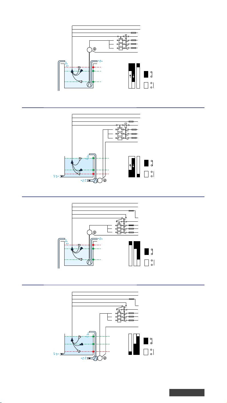
3HE
3
1
2
M
Alarm
Start
U
V
W
Stop
1-2
3-4
High level alarm
6...250 V
L1
L2
L3
PE
Circuit
closed
Circuit
open
DISCHARGING-PUMP CONTROL + ISOLATED LOW LEVEL ALARM
Pump control with one switching element.
3LE
4
3
1
2
U
V
W
Stop
Start
Alarm
M
1-2
Low level alarm
6...250 V
L1
L2
L3
PE
3-4
Circuit
closed
Circuit
open
CHARGING-PUMP CONTROL + ISOLATED LOW LEVEL ALARM
Pump control with one switching element.
5
3YE
4
1
2
3
U
V
Alarm
Start
W
M
Stop
High level alarm
6...250 V
L1
L2
L3
PE
4-5
1-3
1-2
Circuit
closed
Circuit
open
DISCHARGING-PUMP CONTROL + ISOLATED HIGH LEVEL ALARM
Pump control with two switching elements. Take note of the auxiliary contact of the contactor.
3AE
5
4
1
2
3
U
V
W
Stop
Start
Alarm
Low level alarm
6...250 V
L1
L2
L3
4-5
1-3
1-2
PE
Circuit
closed
Circuit
open
M
CHARGING-PUMP CONTROL + ISOLATED LOW LEVEL ALARM
Pump control with two switching elements. Take note of the auxiliary contact of the contactor.
Page 6
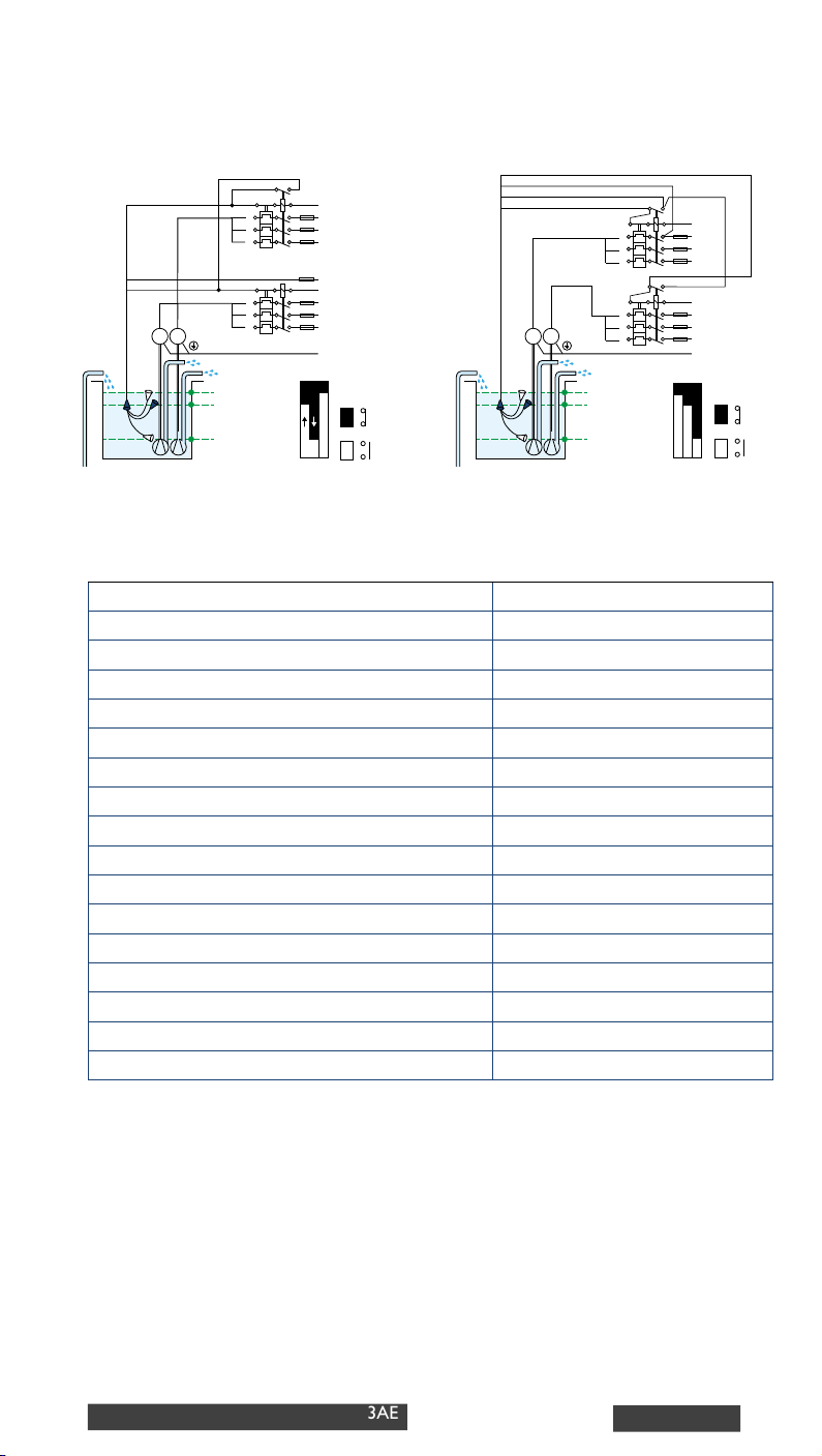
CONNECTION EXAMPLES
Control of two pumps with 3H or 3Y
4
1
3H
3
1
2
Pump 1
Pump 2
MM
U
V
W
U
V
W
Start 2
Start 1
Stop 1 and 2
N
L1
L2
L3
L
N
L1
L2
L3
PE
1-2
1-3
Circuit
closed
Circuit
open
3Y
2
3
Pump 1
Pump 2
MM
U
V
W
U
V
W
Start 2
Start 1
Stop 1 and 2
TECHNICAL INFORMATION
Switching element Microswitch
Voltage 6 ... 250V AC
Max. rated current 6A res., 3A ind.
Rated current with gold-plated contacts
Maximum DC power 75 VA (=0,3A, 250V)
Pressure rating for special types 200 kPa
Max. operating temperature +55 °C (+75 °C supplied to order)
Range of adjustment for standard product (start to stop)
Cable length 5 m (other lengths supplied to order)
Weight of 5 m cable
Largest diameter
Length of oat casing
Buoyancy in water 6 N
Float material Polypropylene (PP)
Cable insulation (standard) PVC
Other cable options Rubber, TPU, teon, silicone
Water-tightness IP 67
1 mA ... 100 mA
200 mm ... 1200 mm
1,6 kg... 1,9 kg
170 mm
155 mm
N
L1
L2
L3
N
L1
L2
L3
PE
1-4
1-3
1-2
Circuit
closed
Circuit
open
3H | 3L | 3Y | 3A | 3HE | 3LE | 3YE | 3AE
Page 7
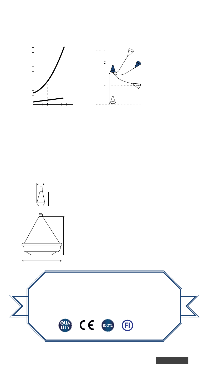
OPERATING CURVES TO
Switching height differential
FLOAT SWITCH ADJUSTMENT
cm
120
100
80
60
40
20
30 50 70 90
Distance of the weight from the float
BD
C
Weight
B
A
The dimensions in
the drawings are for
C
A
cm
illustrative purposes
only.
The switching height differential is adjusted to the required level by means of the
cable weight. Curve B shows the start- and stop-height differential of the KARI Float
Switch in relation to the distance of the weight from the oat. Curve C shows the
corresponding differential between start and alarm levels. Example: For a type 3H
oat switch, if the distance of the weight from the bottom of the oat (A) is 50 cm,
the start/alarm height differential is about 12 cm.
THE DIMENSIONS OF KARI FLOAT SWITCH
55 mm
100 mm
155 mm
ø170 mm
A QUALITY FINNISH PRODUCT
Our quality control is based on the ISO 9001 quality management
system. Each product is subject to a full operation test. The KARI
Float Switch is also available in versions which fullls the U.S. and
Canadian national safety standards.
ROHS
Page 8

 Loading...