

Page 1
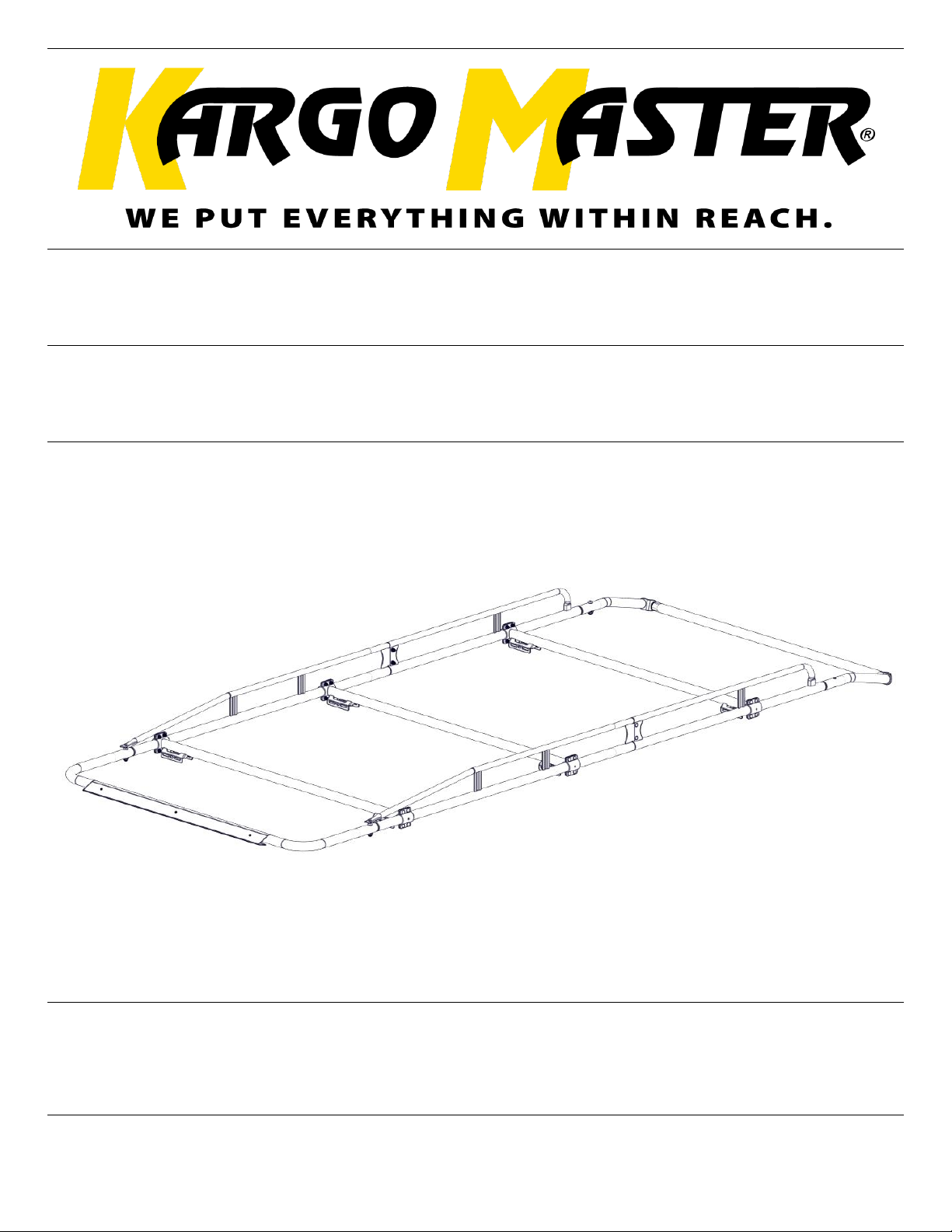
Assembly Guide
40890
DATE: ______________
Page 2
For Technical Support Call: 800-343-7486 Monday-Friday 7AM - 4 PM (PST) Page 1
Assembly Instructions – 40890
*PLEASE READ ALL INSTRUCTIONS AND WARNINGS PRIOR TO ASSEMBLING,
INSTALLING, AND USING THIS PRODUCT*
Warning
Always check for wires, fuel tanks and lines, brake lines and other important vehicle
functionality items prior to drilling and installing all products.
Tools Needed
3/4” Socket and Wrench
9/16” Socket and Wrench
5/16” Allen Hex
Phillips Driver
Table of Contents
Parts List ................................................................................................................................... 3
Hardware ................................................................................................................................. 4
Assembly Instructions
Step 1 – Measure Distance Between Feet ............................................................................ 5
Step 2 – Assemble Side Channels .......................................................................................... 5
Step 3 – Assemble Rack ...................................................................................................... 6-7
Step 4 – Assemble Rear Roller Bar ........................................................................................ 8
Step 5 – Install Wind Deflector .............................................................................................. 9
Before You Begin
• Read all instructions.
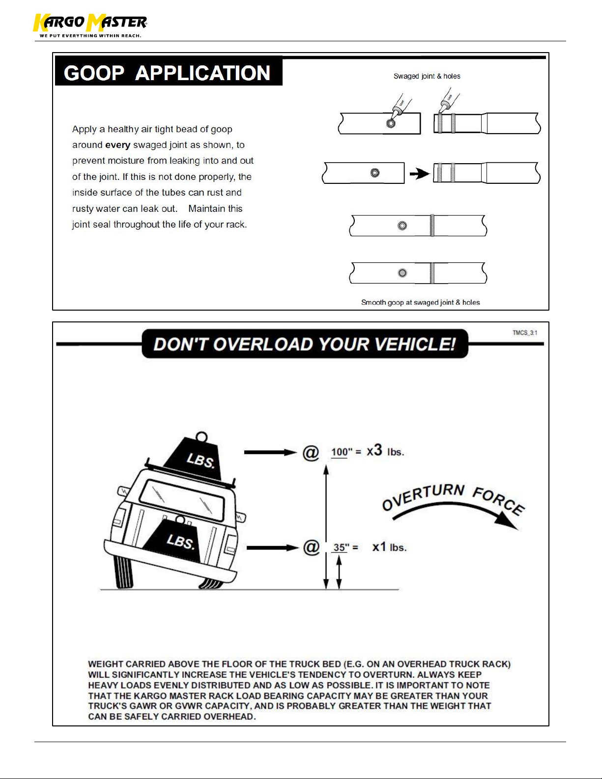
• Be sure to put BH-821 sealant along swage joints and all threads connecting tubes
together. This is to help with water getting into the tubing and causing rust issues.
• During installation onto vehicle, place sealant around all threads entering cargo area and
between the rubber spacer and roof of vehicle to prevent water from leaking into cargo
area.
Page 3
For Technical Support Call: 800-343-7486 Monday-Friday 7AM - 4 PM (PST) Page 2
Assembly Instructions – 40890
Page 4
For Technical Support Call: 800-343-7486 Monday-Friday 7AM - 4 PM (PST) Page 3
Assembly Instructions – 40890
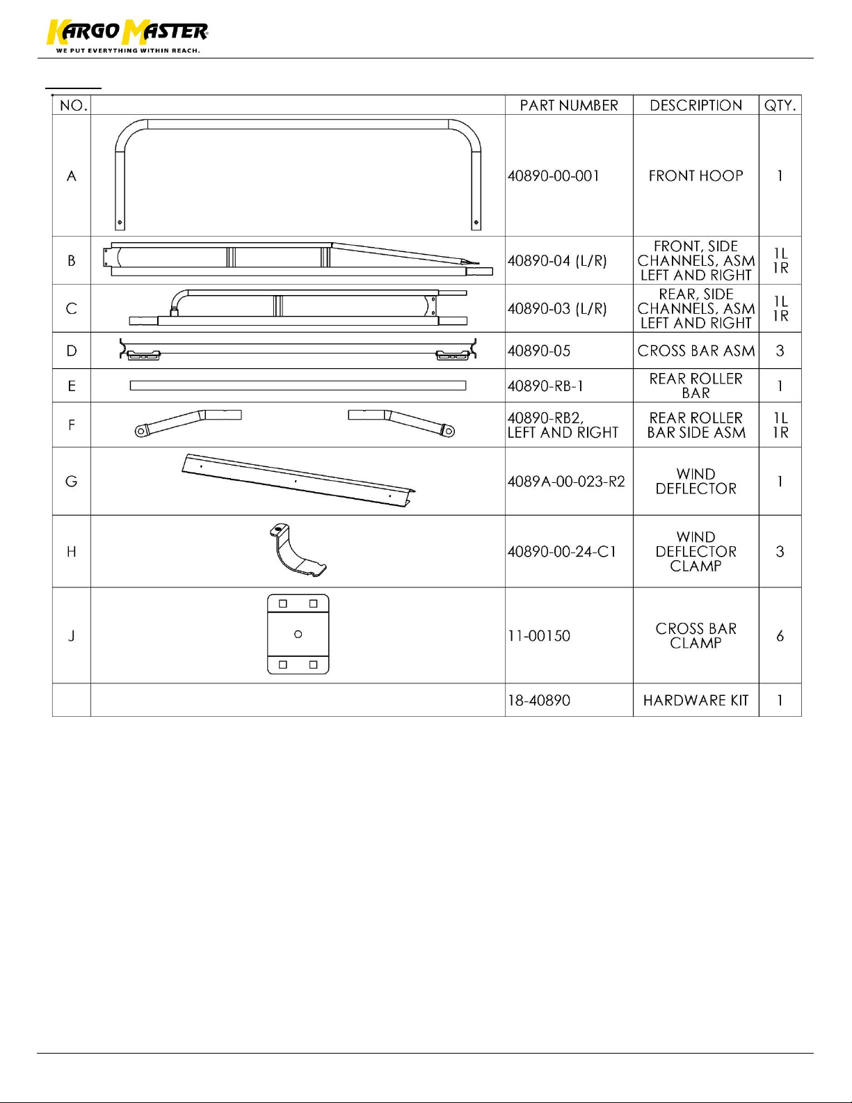
Parts
Page 5
For Technical Support Call: 800-343-7486 Monday-Friday 7AM - 4 PM (PST) Page 4
Assembly Instructions – 40890
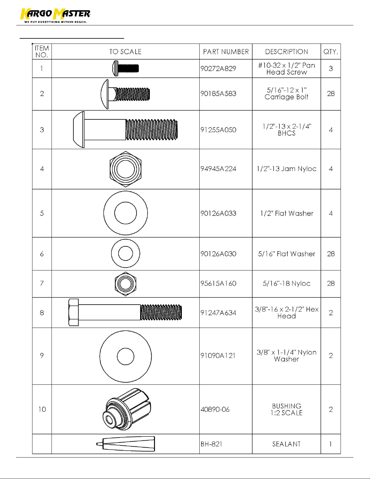
Hardware (18-40890)
Page 6
For Technical Support Call: 800-343-7486 Monday-Friday 7AM - 4 PM (PST) Page 5
Assembly Instructions – 40890
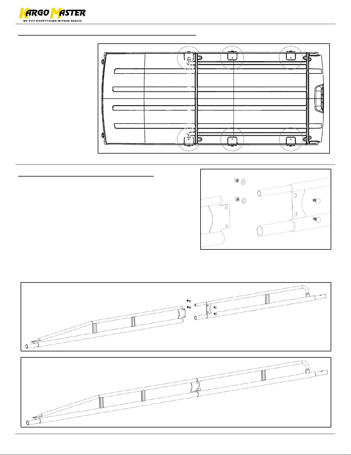
Step 1 – Determine Distance Between Feet
• On the roof of the
van, determine
desired mounting
locations. Measure
between the
locations. This
distance will
determine the
distance between
the cross bar
assemblies of the
rack. (Transit Roof
Shown)
Step 2 – Assemble Side Channels
• Assemble side channels using the front side
channel and the rear side channel. It does not
madder which side the combination of the two will
go on, just be sure to use the correct combinations.
The sheet metal brackets will align properly when
the correct parts are used. See picture.
• Bolt using two 5/16 carriage bolts, two 5/16 flat
washers and two 5/16 nyloc nuts. Repeat for a total
of two rails assemblies.
**Be sure to apply BH-821 around tube connections**
Page 7
For Technical Support Call: 800-343-7486 Monday-Friday 7AM - 4 PM (PST) Page 6
Assembly Instructions – 40890
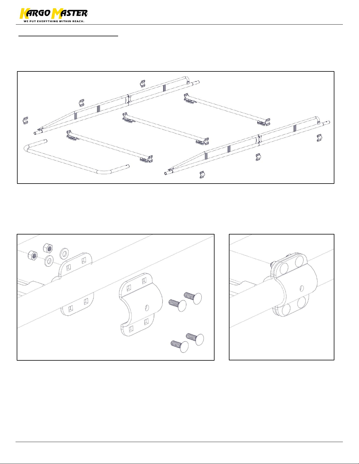
Step 3 – Assemble Rack
• Assemble the rack as shown below.
• Use the distances measured from step one to approximate where the cross bars should go.
• Do not assemble any part of the rear roller bar assembly.
• Once crossbars are in desired position, bolt caps to crossbars using four 5/16” x 1” carriage
bolts, four 5/16” flat washers and four 5/16” nyloc nuts.
• Snug Tighten, but allow movement. Adjustment will be needed when installing on vehicle.
Page 8
For Technical Support Call: 800-343-7486 Monday-Friday 7AM - 4 PM (PST) Page 7
Assembly Instructions – 40890
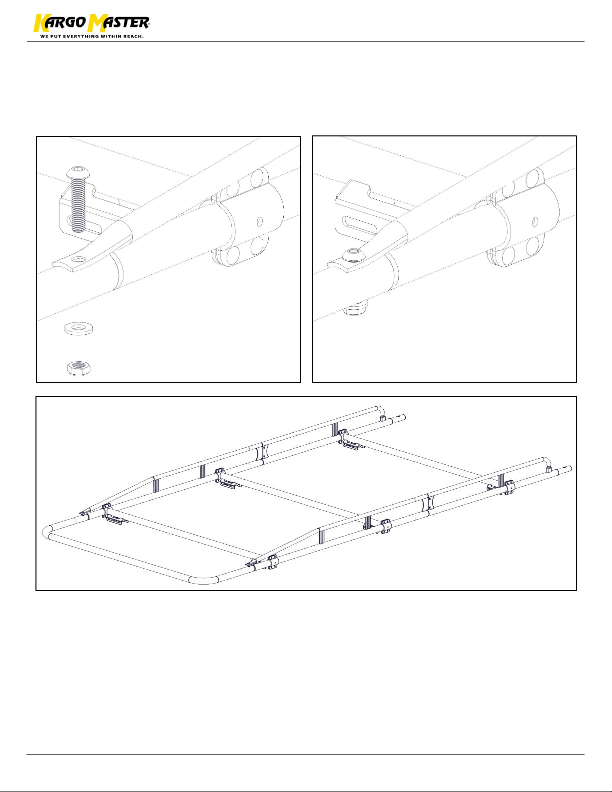
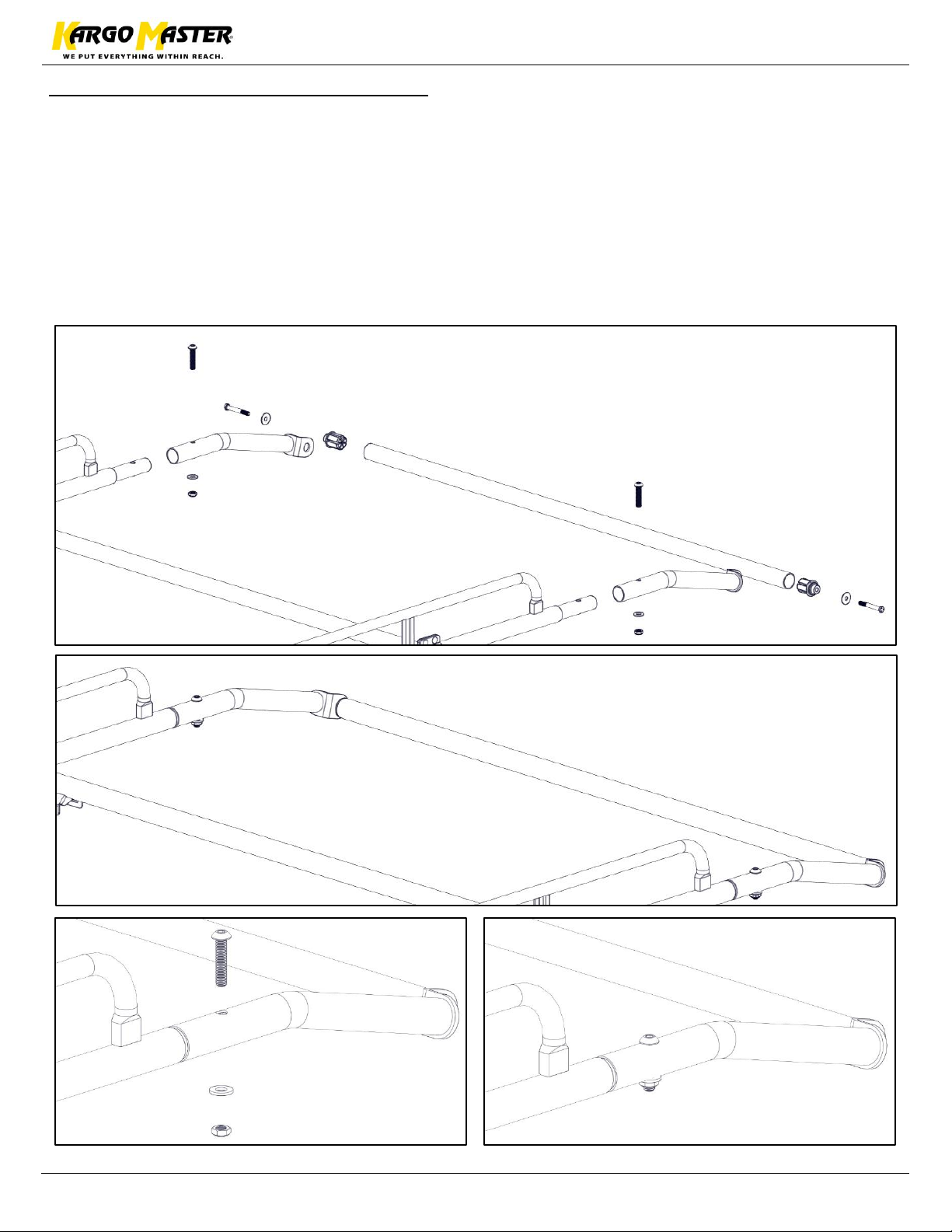
• Bolt front hoop to both side rails using 1/2" x 2-1/4” button head, 1/2" flat washer and a 1/2"
nyloc nut.
• Be sure to place BH-821 along the swage joint.
• Repeat on both sides.
Page 9
For Technical Support Call: 800-343-7486 Monday-Friday 7AM - 4 PM (PST) Page 8
Assembly Instructions – 40890
Step 4 – Assemble Rear Roller Bar
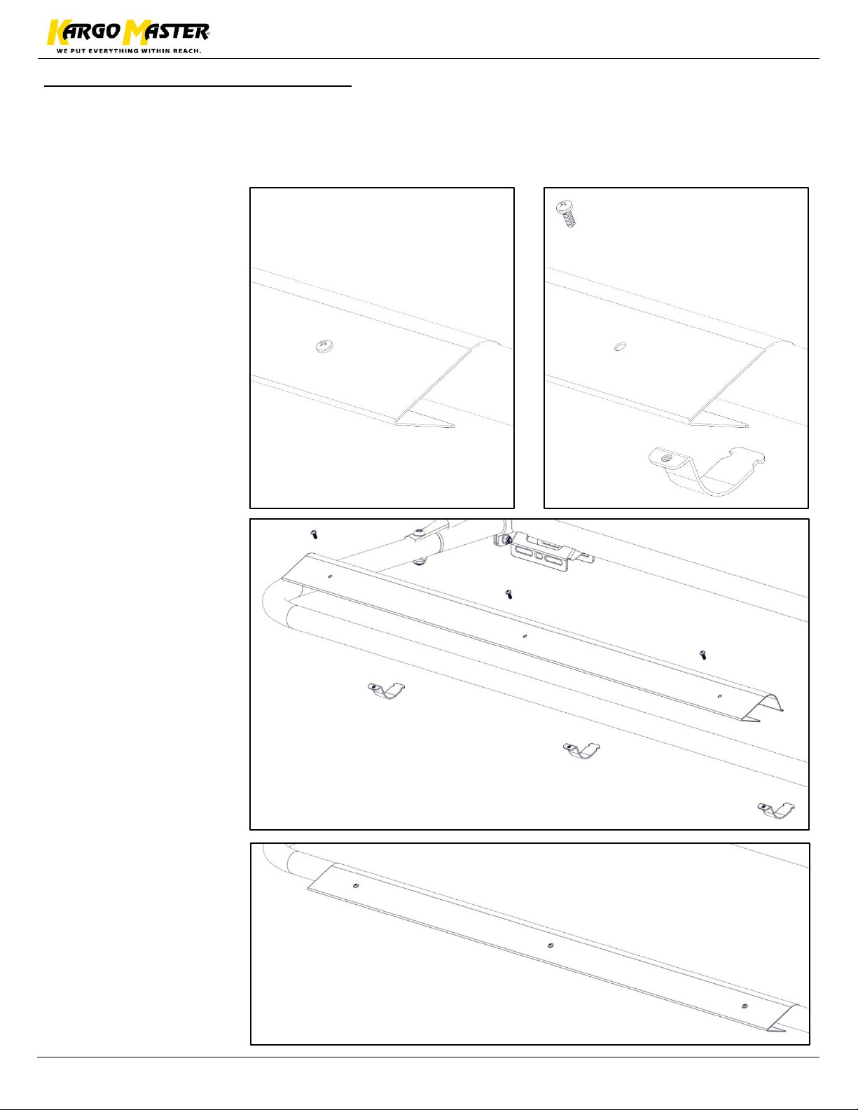
• Insert plastic bushings into the end of the roller bar as shown.
• Bolt roller bar with bushings to the roller bar side assembly using 3/8” oversize washer and
3/8” x 2-1/2” heax head bolt.
• Do not TIGHTEN.
• Bolt both roller bar side assemblies with the rear roller bar to the ends of the side channels
using 1/2" x 2-1/4” button head cap screws, 1/2” flat washers and a 1/2" jam nylocs.
• Once all pieces are attached to the main assembly, one may TIGHTEN.
• Be sure to place BH-821 on all swage joints.
Page 10
For Technical Support Call: 800-343-7486 Monday-Friday 7AM - 4 PM (PST) Page 9
Assembly Instructions – 40890
Step 5 – Install Wind Deflector
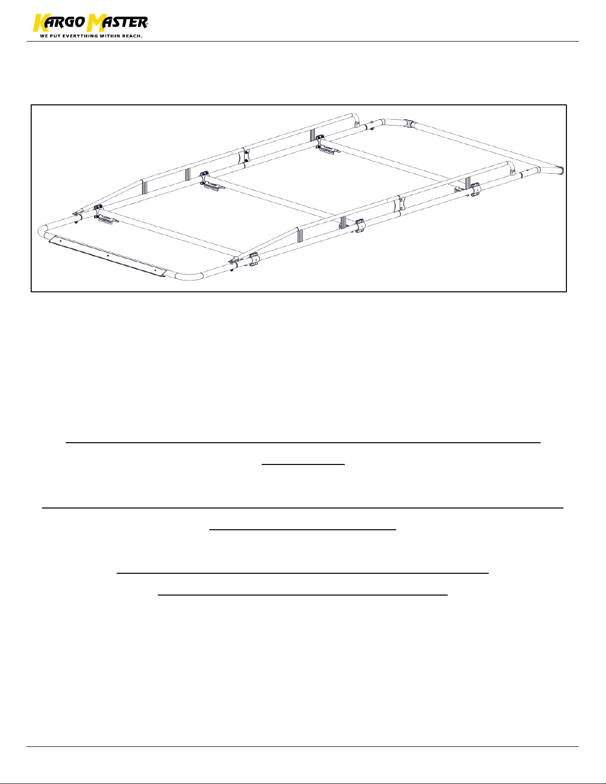
• Place wind deflector along the front hoop. Some adjustment may be needed once vehicle is
driven to minimize road noise.
• Position clamp so it hooks in the slot of the wind deflector and goes around the front hoop.
• Bolt through the
wind deflector and
into the clamps
using a #10 x 1/2"
pan head screw.
• Repeat 3 times.
Page 11
For Technical Support Call: 800-343-7486 Monday-Friday 7AM - 4 PM (PST) Page 10
Assembly Instructions – 40890
Follow the mount kit instructions in the mount kit box to finish the
installation.
Some adjustment on the wind deflector may be needed after driving and
evaluating the wind noise.
GO BACK AND MAKE SURE ALL HARDWARE IS TIGHT
YOUR INSTALLATION IS NOW COMPLETE
 Loading...