

Page 1

Page 2
TECHNICAL REFERENCE AND USER’S GUIDE REVAAA
INTERNAL PAGER SYSTEM CONTROL UNIT
I
CAUTION!
Since PG100-CU Internal Pager System Control Unit is an electronic-based product,
the requirements below should be fulfilled to operate it with full capacity without being
affected by the environmental factors:
The device must not be disassembled by unauthorized
persons in any way.
The cover of the module cabinet should always be kept
closed.
Prior to hanging the module on the wall, one should
make sure screws are not defective.
Precautions must be taken in order to prevent any harmful
substances from leaking or spilling into the module in any
way.
Failure in fulfilling those requirements may result in vital hazards!
PG100-CU TTKK - REVAAA 17/07/2003
KAREL may modify the content of this guide because of any improvement or addition
without any notice. The products may have some differences from the functionality
written in this guide according to the hardware revision or software version.
Page 3

TECHNICAL REFERENCE AND USER’S GUIDE REVAAA
INTERNAL PAGER SYSTEM CONTROL UNIT
II
PREFACE
Chapters in this guide have been prepared in order to present detailed technical
information to people who need hardware-based information about the PG100-CU
Internal Pager System Control, and instructing them for installation of the PG100-RF.
By this way, one could understand abilities of the device, how it will be operated in
accordance with customer demands and things that should be done in order to operate
it with full performance.
The first chapter - “Technical Introduction" It contains, technical information about
hardware and software structures of the device. Information in this chapter for which
knowledge in mechanics, electricity and electronics may be prerequisite, aims to
introduce structure of the device. Presentation of the information in this chapter follows
a path from the whole of the device down to the details of parts.
The second chapter - “Installation” - This chapter tells about the installation methods of
the device. This chapter definitely must be read before the installation by the personnel
who will perform the installation of the device.
The thind chapter - “Use” - This chapter explains the things to be done in order to put
the device in use.
Best regards,
Karel.
III
CONTENTS
TECHNICAL INTRODUCTION:..............................................................................................1
INTRODUCTION TO THE PG100-CU UNIT:............................................................1
PARTS LIST ON DELIVERY:.....................................................................................2
COMPATIBILITY:..................................................................................................2
TECHNICAL SPECIFICATIONS:..................................................................................2
INSTALLATION:...............................................................................................................3
PREPARATION:.................................................................................... ..............3
APPLICATION:.............. ..... .......................... ..... .......................... .....................3
WIRING OF THE PG100-CU UNIT:.............................................................................4
Power Connection:.................................................................................................4
PG100-RF Connection:...........................................................................................4
Exchange Connection:.............................................................................................5
USE:.... ..... ..... ..... ..... ..... ..... ..... ..... ... .. ... .. ... .. ... .. ... ..... ..... ..... ..... ..... ..... ..... ..... ....6
Page 4

TECHNICAL REFERENCE AND USER’S GUIDE REVAAA
INTERNAL PAGER SYSTEM CONTROL UNIT
TECHNICAL INTRODUCTION
INTRODUCTION TO THE PG100-CU UNIT
The PG100-CU unit is one that transfers call information to several PG100-RF local
pager devices and that provides synchronous operation of the transmitters. In case
coverage area of a single PG100 local pager transmitter is insufficient, it is possible to
employ several transmitters (PG100-RF) by utilizing a PG100-CU control unit, so that
the coverage area can be extended. The PG100-CU unit is used with the PG100-RF local
transmitter units. The PG100-CU unit transfers the call information, which is transmitted
from the Karel exchange, to the PG100-RF transmitters and provides synchronous
operation of the transmitters. At most four PG100-RF units can be connected to a single
PG100-CU unit.
The PG100-CU unit receives the call information over the Karel KTS line (data line)
or over the standard TIA/EIA-422 (RS422) line and then transfers it to the PG100-RF
transmitters over the RS422 lines.
Appearance of the PG100-CU unit is as follows:
1
Figure-1
• PG100-CU Synchronizer Unit
• DTB04 Feed Connection Cable
• PG100-CU Technical Reference and User’s Guide
The PG100-CU unit is compatible with the MS38S and the Karel exchanges with higher
capacities, provided that their software version is 3.08 or later, and it is also compatible
with DS series exchanges with software version 1.05 or later.
2
PARTS LIST ON DELIVERY
TECHNICAL SPECIFICATIONS
COMPATIBILITY
Page 5

TECHNICAL REFERENCE AND USER’S GUIDE REVAAA
INTERNAL PAGER SYSTEM CONTROL UNIT
3
INSTALLATION
PREPARATION
The PG100-CU internal pager system has been designed so as to be mounted on wall
surfaces. First of all, the location to install the device should be determined. Such a
location is supposed to possess the properties listed below, in order for the PG100-CU
unit to operate in the most efficient way:
• The room in which the device will be installed should be clean, dust-free and the
system should not be exposed to direct sunlight.
• The environmental temperature should be in the range 0 C°- 40 C° and the humidity
should not exceed 80 %.
• No metal objects should be in the vicinity of the device, for they might
affect antenna performance.
• Locations of the electrical outlet and DTB04 if there is one should be taken into
consideration.
• Locations of the PG100-RF transmitters should be taken into consideration.
• The box should be mounted at a position so that the front cover will easily be
opened, which is 100-160 cm above the floor.
APPLICATION
The PG100 comes with a mounting template and two anchor plugs pairs. The “Mounting
Template”, which is supplied together with the module, is supposed to be used in order
to determine the location of the module and spots for the holes that are required for the
installation.
In order to hang the PG100 on the wall:
• Place the mounting template on the wall surface.
• Drill holes on the wall at two points determined through the mounting template.
• Insert the anchor plugs into the holes.
• Insert screws into the anchor plugs and drive them in until a 7 mm-portion of their
heads remain outside the wall surface.
• Hang the device onto those screws through the pear holes, which are on the back cover.
WIRING OF THE PG100-CU UNIT
Power Connection:
The PG100-CU unit is fed on -48 VDC. The product DTB04 can be used for feeding.
The connection cable to the DTB04 unit is supplied with the PG100-CU unit. The cable
connector is attached to the FEED connector. Utilization of the BK38 battery unit,
alongside with the DTB04 unit, prevents blackouts from disrupting communication and
makes the system remain functional for at least 10 hours.
PG100-RF Connection:
The connections, which provides for PG100-RF transmitters both data transmission and
voltage feed upon wish (-48 VDC), are made to the PAGER_TX connectors within the
PG100-CU. Signal assignments for the connector have been shown in the figure below.
The cable that extends out of this connector is supposed to be attached to the connector
PG100-CU, which is on the product PG100-RF. Cable length should be less than 1 km for
copper cable with diameter of 0.5 mm. In case the feed is not applied for the PG100-RF
unit, it will be sufficient if only the RS422_POS and RS422_NEG signals of the PAGER_TX
connector are carried over the cable connection.
PAGER_TX connector signal assignments
4
Figure-2: The PG100-CU unit connection layout
Page 6
TECHNICAL REFERENCE AND USER’S GUIDE REVAAA
INTERNAL PAGER SYSTEM CONTROL UNIT
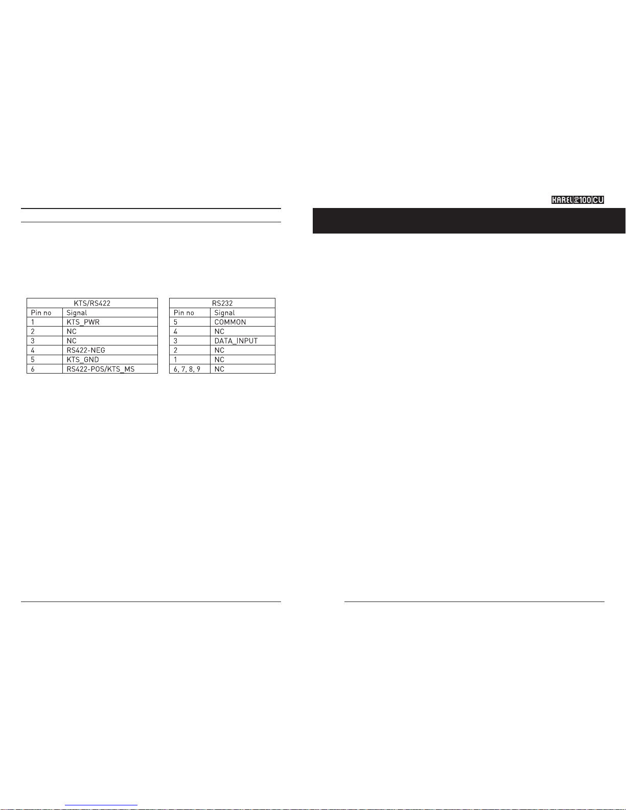
Exchange Connection:
Connection to the MS series exchanges can be made over the KTS interface and to the
DS series exchanges over either KTS or RS422 interfaces. Signal assignments for the
KTS/RS422 and RS232 connectors have been shown in the figure below. Tips specified
as “NC” indicate that no connection will be made there. The tip RS422_POS and KTS_MS
is common for the KTS and RS422 connection. When a connection is made to a PC over
RS232, 9-pin D-type DCE-DTE serial cable should be used. When the RS422 connection is
made, the cable length should be less than 1 km for copper cable with diameter of 0.5 mm.
KTS/RS422 and RS232 connector signal assignments
5
6
The PG100-CU unit starts to operate after its connections have been completed.
USE
Page 7

TECHNICAL REFERENCE AND USER’S GUIDE REVAAA
INTERNAL PAGER SYSTEM CONTROL UNIT
7
8
Page 8

TECHNICAL REFERENCE AND USER’S GUIDE REVAAA
INTERNAL PAGER SYSTEM CONTROL UNIT
9
10
Page 9

TECHNICAL REFERENCE AND USER’S GUIDE REVAAA
INTERNAL PAGER SYSTEM CONTROL UNIT
11
12
 Loading...