

Page 1
Page 2

IP SIP TELEPHONE SET
TECHNICAL REFERENCE
AND
USER GUIDE
FEBRUARY - 2012
Page 3
NT32I Technical Reference and User Guide
II
Page 4

NT32I Technical Reference and User Guide
III
Version Table
Guide Date/Version
AAA/02.02.2010
AAB/07.02.2012
NT32I Tech. Ref. and User Guide – Ver. AAB – 07.02.2012
KAREL reserves the right to make modifications in product features mentioned in
this document for development and improvement purposes, without prior notice.
Individual products may possess characteristics different from those that have
been mentioned in this document, due to their differences in software and
hardware versions.
Page 5
NT32I Technical Reference and User Guide
IV
NT32I
Page 6

NT32I Technical Reference and User Guide
V
ISSUES TO PAY ATTENTION TO
♦ Read this guide carefully before you use your device and keep it for later
reference.
♦ Any mistake with the connections in your device may damage it or your
exchange. Especially the connection to the exchange must be made by
the Authorized Technical Services. The explanations about connections in
the User’s Guide have been intended to give information only.
♦ A connection box comes with your device. The connections must be made
as described in the installation chapter.
♦ In case you need a connection of plug-outlet type, never apply electric
plugs and outlets; use plugs, outlets and connection components that are
specific to telephones.
♦ Do not make any connection other than the extension connection of the
KAREL telephone system.
♦ There is no part that you can repair or maintain in your device; therefore
call the authorized technical service in case of any malfunction.
♦ Keep your device away from direct sunlight.
♦ Do not let any liquid substance spill on your device.
♦ Do the exterior cleaning of your device with a slightly moistened piece of
cloth.
♦ Do not apply any chemicals for cleaning.
♦ Please call your authorized dealer in case you would like to change the
place of your device. Use its own packing to carry the device.
♦ Please do not use exterior signal for the test operations or maintenance.
Any signal which is used externally may damage your device.
Page 7

NT32I Technical Reference and User Guide
VI
PREFACE
Chapters in this guide have been prepared in order to give basic information about
the NT32I IP Phones.
- The basic information about features of the phone has been given and the
hardware of the device is described.
- The keys required for basic use of the phone's are mentioned.
- The hardware requirements of the phone are mentioned and the
connection details are given.
- Required and alternative settings on the NT32I Phone Set are described
for users.
- In case there is a problem, the information about points that must be
considered is given.
Best Regards,
KAREL
Page 8

NT32I Technical Reference and User Guide
VII
CONTENTS
TECHNICAL INTRODUCTION ............................................................. 1
Basic Specifications of NT32I ............................................................ 1
Specifications of NT32I ...................................................................... 2
INTRODUCTION ................................................................................... 4
Parts List on Delivery ......................................................................... 4
GENERAL APPEARANCE ................................................................... 5
NAVIGATION KEYS AND SPECIAL FUNCTION KEYS ..................... 6
PHYSICAL CONNECTIONS ................................................................. 8
NT32I NETWORK SETTINGS .............................................................. 9
NT32I WEB SETTINGS ...................................................................... 15
System Information .......................................................................... 16
Network Settings .............................................................................. 16
SIP Settings ..................................................................................... 17
TROUBLESHOOTING ........................................................................ 20
Page 9

NT32I Technical Reference and User Guide
1
TECHNICAL INTRODUCTION
Basic Specifications of NT32I
VoIP Protocols
• SIP v2.0 (RFC3261)
Call Features
• Call Back – Calling the caller of last incoming call
• Call Blocking – Blocking all incoming calls
• Call Holding – Holding the existing conversation (10
incoming calls can be put on hold simultaneously.)
• Call Transfer – (Selective Transfer/Direct Transfer)
• Call Forwarding – Forwarding incoming calls
• Automatic Answering
• Emergency Calls
• 3-Party Conference
Display Panel
• Graphic LCD screen
• Caller ID
• Display of simultaneous incoming calls
• Date and Time Displayer
• Light and Contrast Adjustment
Easy to Use
• Programming via WEB
• Installing software, configuration and phonebook over
Web/TFTP
• Recall user settings when machine is restarted
• Backup and re-installing phonebook, configuration and
key programming files. Installing prepared phonebook.
Keys
• 6 shortcut keys
• 4 display keys
• 4 navigation keys
• Volume control keys
• Numeric keys
• Special Function Keys
- Contacts
- Call Log
- Menu
- Message
- Redial
- Conference
- Park
- Transfer
Language
• Turkish / English
Dimensions
• Dimensions: 228 x 217 x 147 mm
• Weight: 960 gr.
Temperature
• 5-40°C
Humidity
• 0-%80
Page 10

NT32I Technical Reference and User Guide
2
Specifications of NT32I
Codecs
•
G.711A
• G.711U
• G.723
• G.726 16 Kbps
• G.726 24 Kbps
• G.726 32 Kbps
• G.726 40 Kbps
• G.729
G.723 Ratio
•
5.3 Kbps
• 6.3 Kbps
LAN Protocols
•
SIP v2.0
• IP/TCP/UDP/RTP/RTCP/ICMP/ARP/RARP/SNTP
• TFTP Server
• DHCP/DNS/SNTP Client
• HTTP Server
• Static/DHCP IP Assignment
• NAT transversal
- STUN - NAT
DTMF
•
In-Band
• Out-of-Band DTMF (RFC2833)
• SIP Info
Voice Quality
•
VAD – Voice Activation Detection
• AGC – Automatic Gain Control
• AEC– Acoustic ECHO Cutter
• Jitter Buffer
Tones
•
Ring tones – 5 different ringtones
• Changeable and installable ringtones
• Warning tone on busy
Power
• 5 VDC adaptor
Phone Functions
•
Message and Call displayer
• Remote SIP registration – Ability to register to 3 different
registration servers. (Sequentially registration or
registration to selected registration server)
• Recorded user settings
• Call Records (128 records are kept for each of Missed,
incoming and outgoing. Last 32 call records are kept for
every extension.)
• Full duplex speaker
• 2 internal 10/100 Ethernet switch ports
• Speed Dial / 6 + 24 (with DSS module)
• Phonebook – 128 numbers
• Hour/Day/Week/Month/Year basis 8 different periodical
alarm, alarm message or name definitions.
Page 11

NT32I Technical Reference and User Guide
3
Bluetooth
•
Fully Qualified Bluetooth system v2.0 + EDR, CE and
FCC
• Integrated chip antenna
• Enhanced Data Rate (EDR) compliant with v2.0.E.2 of
specification for both 2Mbps and 3Mbps modulation
modes
•
Full Speed Bluetooth Operation with Full Piconet
Page 12

NT32I Technical Reference and User Guide
4
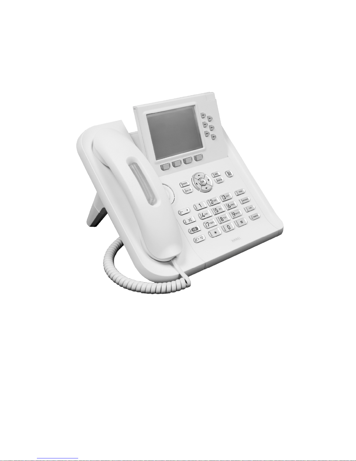
INTRODUCTION
NT32I is IP based telephone which is perfectly compatible with KAREL’s new
generation IP PBX systems with its superior and advanced properties. NT32I
provides cheaper voice communication with high quality over existing IP lines.
Internet output can be transmitted to computers with second ethernet port of
NT32I which supports NAT.
Parts List on Delivery
- NT32I Telephone
- Telephone Handset
- Spiral cable of the handset,
- Ethernet Cable
- AC Power Adaptor
- Product Quality and Warranty Cards
- Technical Reference and User Guide CD
NT32I Telephone Handset
Ethernet Cable AC Power Adaptor Guide CD
Page 13

NT32I Technical Reference and User Guide
5
GENERAL APPEARANCE
1 HF Speaker 5 Screen Adjustment Plug ** 9 Navigation Keys
2 Incoming Call LED* 6 Shortcut Keys 10 Special Function Keys
3 Handset 7 Display Keys 11 Numerical Key Pad
4 Screen 8 Special Function Keys 12 Voice Control Keys
* Incoming Call LED is also used for warning for messages.
** Height of the screen must be adjusted with using this plug.
Page 14

NT32I Technical Reference and User Guide
6
NAVIGATION KEYS AND SPECIAL
FUNCTION KEYS
“OK
” key : This key is for user to confirm the setting or activate the function
that is displayed on the screen.
“Navigation
, , , ” keys: These keys help user to move at all menus and
choose the option which user wants.
“Contacts” key: It activates phonebook. It helps user to enter a new number,
delete existing number or reach existing numbers.
“Call Log” key: It activates Call Records Menu. It helps user to reach all call
history.
“Menu” key: It helps user to enter or exit the menu that user can adjust all
telephone settings.
“Function” key: It is allocated for future needs. Any function can be assigned
to this key as other programmable keys.
“Message
” key: This key is used for reaching messages. User can
understand whether s/he has got an un-listened message or not.
“Redial” key: Dials again the last called number.
“Conference” key: This key is used for starting a conference while making an
external or internal call.
“Park” key: This key is used for parking the existing call.
“Transfer” key: This key is used for non-announced (without warning other
extension who is going to take the call) or transfer an existing call to an
extension with announcement.
Page 15

NT32I Technical Reference and User Guide
7
Shortcut Keys
These Shortcut Keys can be assigned to any function which may be a speed
dial to a number from phonebook, call park, auto-answer, do not disturb, call
forward or any page at the menu.
Voice Control Keys / Headset Key
According to Headset controls under General Setting menu, the operations of
these buttons are changed. If Headset control is activated, this button is used
for activating the headset. When an incoming call is answered with using this
key, the conversation will be made by using headset and when conversation
ends, headset will be inactive.
However if the headphone control is inactive, this key will be used for starting a
new call. During a conversation or stand-by mode or calling mode, this key is
used for starting a new call.
Page 16

NT32I Technical Reference and User Guide
8
PHYSICAL CONNECTIONS
Connectors, which are connection places of LAN, AC Power Adaptor, Headset,
Headset cables, are placed at the back of NT32I. For fast installation, firstly
headset connection has to be made. Then with making AC Power Adaptor
connection, telephone will be started. Finally LAN connection will be made with
an ethernet cable.
NT32I, which is connected to LAN, will not work because NT32I has not got an
IP address by default. All information about adjusting IP settings or registering
an IP system is explained in the related chapters of this guide. Please make
programming after checking to those chapters.
Page 17

NT32I Technical Reference and User Guide
9
NT32I NETWORK SETTINGS
After making required installations, when telephone is powered on, this screen
will be seen:
With using display keys, user can enter menu, other sub menus. After entering
Menu, following 8 main menus will be seen:
- Phonebook
- Call Records
- Messages
- System Settings
- Settings
- PBX Settings
- Alarm
- SIP Settings
An IP address should be assigned to NT32I because of not having an IP
address by default. This operation will be made from
Menu>Settings>Telephone Settings>Network Settings menu.
Page 18

NT32I Technical Reference and User Guide
10
Enter “Settings” menu by using navigation keys.
After entering Settings menu with pressing “Select” key, enter “Telephone
Settings” menu again with “Select” key.
Page 19

NT32I Technical Reference and User Guide
11
Menus, which will help user to assign IP address to NT32I, are at “Network
Settings” under “Telephone Settings” menu.
After entering “Network Settings” menu, an IP address should be assigned to
NT32I with using existing LAN information. While assigning an IP address to
NT32I, please contact to IT service of your company to avoid IP overlaps.
Page 20

NT32I Technical Reference and User Guide
12
To activate NT32I telephone set, firstly;
- IP Type
- IP Address
- Netmask
- Gateway definitions must be done.
There are two options for IP type:
Static IP: User can adjust IP address and Subnet Mask manually.
DHCP: DHCP server makes all necessary network adjustments automatically.
Page 21

NT32I Technical Reference and User Guide
13
Select IP type ad Static and then press Confirm.
After selecting IP type as Static, then make the adjustments listed below:
- IP Address
- Netmask
- Gateway
Please ask your company’s authorized person about IP settings that are
made.
After entering IP address, Netmask and Gateway addresses, press “confirm“ to
save these addresses. Press “Back” to exit from menu. Before exiting from
“Network Settings” menu, “Save Changes” will be seen at the screen.
Page 22

NT32I Technical Reference and User Guide
14
Press “Yes” to save the changes and a message will occur to inform user that
the changes are saved.
Other adjustments can be made easily by using special web interface for NT32I.
Adjusting other settings with using web interface will be told at the rest of user
guide.
Page 23

NT32I Technical Reference and User Guide
15
NT32I WEB SETTINGS
Enter IP address of NT32I to one of your computer’s web browser. Be sure that
your computer is connected to LAN. Press “Enter”.
For example, the IP address of this NT32I is 192.168.178.247. Then the page
below is going to be seen.
Enter default password (123456) to the box which is shown above, and then
press “OK”. (Default entry password can be changed from System Settings >
Http Password.
Page 24

NT32I Technical Reference and User Guide
16
System Information
System Information can be seen from this page.
Network Settings
By clicking on Network Settings, user can check or change settings which are
made manually.
DNS setting should be adjusted by asking authorized persons.
Page 25

NT32I Technical Reference and User Guide
17
NT32I telephone set can register to 3 different servers but not at the same time.
Defined servers can be activated whenever user wants.
Entries about server or IP PBX are made from SIP Settings menu.
SIP Settings
Page 26

NT32I Technical Reference and User Guide
18
SIP Register
This option must be “Enable” to make conversations over SIP server or IP PBX.
When user registered to server, s/he can make connections with analog and
digital extensions and use services that server supports.
If this option is selected as “Disable”, user of NT32I can only make IP – IP
conversations.
SIP Register Choice
User can choose to select SIP server automatically or manually. If it is selected
as “automatic”, telephone will try to register one of these SIP servers. If it is
selected as “manual”, telephone will try to register one of SIP server which is
chosen by user.
Server Choice
The SIP server, which user wants to activate, is chosen from this part. User
should mark SIP server which s/he wants to use.
X.Server IP
This part is used for defining 3 different SIP servers or IP PBX’s or URL.
X.Server Port
This part is used for entering port number of SIP Server. Default value is 5060.
User ID
This part is used for entering user’s account information.
Service ID
This part is used for entering SIP Service ID.
Password
This part is used for entering SIP Password.
User Name
This part is used for entering the name which will be shown at the LCD screen
of NT32I telephone set.
SIP Port
This part is used for entering the port number which telephone will use for SIP
communications. This number may be between 1024 and 65535. Default value
is 5060.
Page 27

NT32I Technical Reference and User Guide
19
RTP Port
This is used for sending and receiving RTP. This number may be between 1024
and 65535. Default value is 4000.
Record End
At this part the value of time is selected. This time shows the intervals (in
seconds) to send “Keep alive” to SIP Server. Minimum is 10 sec. and maximum
is 655535 sec. Default value is 60 sec.
Keep Alive
“Keep alive” shows the time that in how many seconds telephone will send
empty UDP to SIP server again. Default value is 20 seconds.
DTMF Mode
This part is used for defining the way how DTMF digits will be sent. There are 3
different way to send DTMF.
- Inband
- RFC2833
- SIP Info
NAT /NAT IP
This is used to enable or disable NAT device.
STUN
At the beginning, entering STUN server’s IP address or entries about server will
be enough. After making all adjustments, click on “Save” to activate the
changes.
After making all adjustments about NT32I telephone set, IP user information
should be defined. This is obligatory and must not be forgotten.
If server can not get user information correctly, NT32I will send REGISTER
message to server in regular intervals. If server can not identify user, NT32I
shows “Registration Failure” on the screen.
If telephone registers to the server normally, telephone can communicate with
predefined analog and digital telephones and use all services that server
supports.
STUN Port
This part is used for entering port number parameter of STUN. This number
may be between 1 and 65535. Default value is 3478.
Page 28

NT32I Technical Reference and User Guide
20
TROUBLESHOOTING
Telephone does not work even power connection is made.
Be sure that adaptor cable is connected to plug. Check that there is voltage at
the plug and be sure that there is voltage at the plug. If every connection is OK,
wait 25-30 seconds. Telephone will start. If telephone is still closed, take the
adaptor cable back from the plug and contact with service.
Physical Connections are OK but can not connect to WEB interface.
Check physical connections of your telephone. Check the place of LAN
connection at the telephone is correct. Be sure that ethernet cable is OK. Check
whether IP configuration of the telephone is correct. Check whether the same IP
is used by other machine at the same LAN or not. If yes, contact to authorized
person. Check whether Gateway address is entered correctly. Ping to
telephone’s IP from other computer at that LAN. (by using Command Prompt
and write C:\ ping 192.168.178.247.) If you get response, you can open web
interface, if not please check network settings and check whether they are the
same with NT32I or not. If problem is not solved, please contact with service.
If “Registration Failure” appears.
Check whether telephone LAN cable is connected or not and check whether
cable is OK. If problem continues, please check SIP Settings again. Be sure
about SIP server IP and IP PBX settings. Verify your server username and
password. If problem is not solved, please contact with service.
If telephone is ON but “No service” message occurs.
Be sure that the software of telephone is installed completely. For this purpose,
check System Settings > System Information. Be sure that all cable connections
are made completely. Check Network Settings again. If problem is not solved,
please contact with service.
Page 29

 Loading...