

Karel MS48 Installation & Maintenance Manual

Karel MS48
Telephone System
Installation
&
Maintenance
Guide
Edition 3.2

i
CONTENTS
SECTION
PAGE
INTRODUCTION 1
TECHNICAL REFERENCE
I. SYSTEM 3
I.1. MB48 MOTHERBOARD & EXP48 EXPANSION MODULES 5
I.2. POWER TO THE SYSTEM 8
I.2.A. SPS48 POWER SUPPLY MODULE 8
I.2.B. POWER FAILURE TRANSFER STATIONS 10
I.3. EXTERNAL MUSI C CONNECTOR 10
I.4. EXTERNAL RELAY 10
II. ACCESSORIES 11
II.1. CONSOLES, FEATURE PHONES, DIRECT STATION SELECT
MODULES – OP48(-H), LT48(-H), DSS80, DSS40
11
II.1.A. OP48(-H) CONSOLE 12
II.1.B. LT48(-H) FEATURE PHONE 13
II.1.C. DSS80 DIRECT STATION SELECT MODULE 13
II.1.D. DSS40 DIRECT STATION SELECT MODULE 14
II.2. MINI PRINTER - KY16 15
II.3. CALL RE CORD LI STING INTERFACE – CM48 17
II.4. PC-CONSOLE INTERFACE – PK48 19
II.5. CALL RECORD LISTING & PC-CONSOLE INTERFACE - CM48 +
PK48
20
II.6. SERI A L PRINTER INTERFACE - RS232 20
II.7. DOORPHONE - DY26 21
II.8. EXTERNA L ANNOUNCEMENT SYSTEM 21
II.9. AUTO ATTENDANT & VOICE MAIL – EVM48 22
II.10. ISDN ADAPTOR - IA 12, EXP-IA12 23
II.11. LOCAL PAGER – PG100 26
II.12. STANDARD TELEPHONE SETS 27
II.13. FILTER & PROTECTION UNIT – FPBASE, FPEXP 28
III. SOFTWARE 29
IV. TECHNICAL SPECIFICATIONS 31

ii
SECTION
PAGE
INSTALLATION
I. PRELIMINARY NOTICE 33
I.1. DELIVERY CHECK 33
I.2. INSPECTION 33
I.3. ENVIRONMENTAL REQUIREMENTS 33
II. SYSTEM INSTALLATION 35
II.1. GROUNDING 36
II.2. SPS48 POWER SUPPLY MODULE 37
II.3. MB48 MOTHERBOARD & EXP48 EXPANSION MODULES 38
III. ACCESSORY INSTALLATION 41
III.1. CONSOLES, FEATURE PHONES, DIRECT STATION SELECT
MODULES
41
III.2. MINI PRINTER 45
III.3. PC INTERFACE 49
III.4. SERIAL PRINTER INTERFACE 50
III.5. DOORPHONE 51
III.6. EXTERNAL ANNOUNCEMENT SYSTEM 53
III.7. AUTO ATTENDANT & VOICE MAIL 54
III.8. ISDN ADAPTOR 55
III.9. LOCAL PAGER 58
III.10. STANDARD TELEPHONE SETS, EXTERNAL LINES 61
III.11 FILTER & PROTECTION UNI T 62
III.12. EXTERNAL MUSIC SOURCE 63
III.13. EXTERNAL RELAY 64
MAINTENANCE
I. MAINTAINING THE SYSTEM 67

INTRODUCTION
This Installation and Maintenance G uide provides an overall technical
reference on the KAREL MS48 system and its accessories and
includes descriptions, structures and capabilities as well as the
installation and maintenance information.
This guide is formed up of three main chapters:
1) Technical Reference: The system outline is given and all the
accessories are described. Brief information about the software
structure of the system is presented and finally the technical
specifications of the system are listed.
2) Installation Guide: The basic system installation and wiring
instructions are presented. Follow ing the system installation p art,
the installation and the wiring of the accessories are explained.
3) Maintenance Guide: The basic steps to solve the problems faced
after the installation of the system are given.

Karel MS48 Installation & Maintenance Guide
Edition 3.2
3
I. SYSTEM
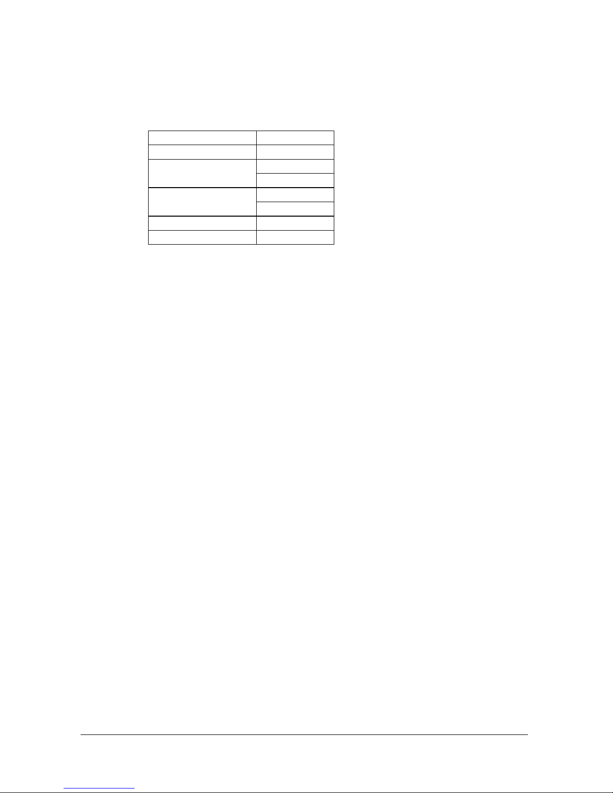
At minimum capacity, MS48 has 4 lines and 12 extensions, which can be further
upgraded to support the following configurations :
Lines Extensions
4 28
18
6
34
24
8
40
10 30
12 36
At minimum capacity, the MS48 system consists of the following parts :
•
CBN48 Cabinet made of metal,
•
SPS48 Power Supply Module including a power card and cables,
•
PWT48 Power Transformer,
•
RNT48 Ring Transformer,
•
MB48 Motherboard that can support the minimum capacity of 4/12.
The EXP48 Expansion Modules may be used to increase the system capacity.
Karel MS48 Installation & Maintenance Guide
Edition 3.2
4
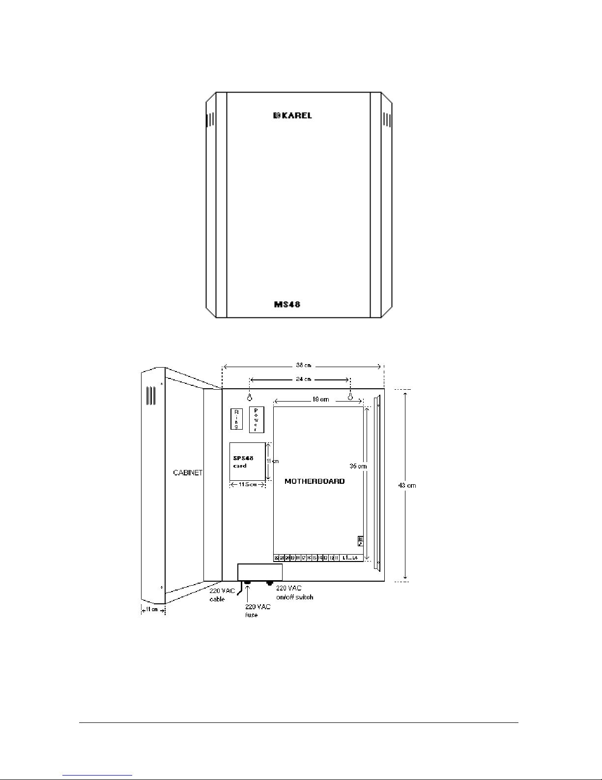
See the following figures to have a general idea about the outlook as well as the
structure of the system.
Figure A-1
Figure A-2
The CBN48 metal cabinet provides a strong shell and a natural electromagnetic
shield for the system.
Karel MS48 Installation & Maintenance Guide
Edition 3.2
5
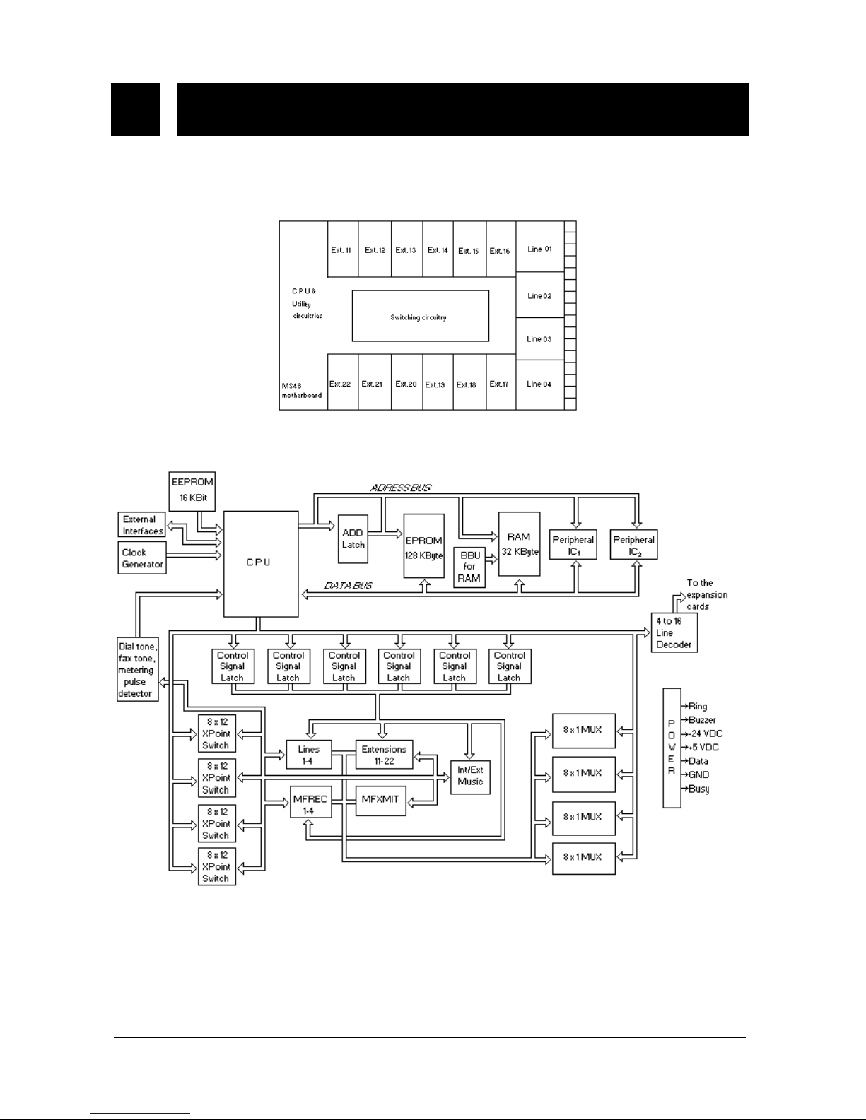
I.1. MB48 MOTHERBOARD &
EXP48 EXPANSION MODULES
The MB48 motherboard consists of the microprocessor, utility, DTMF, switching,
line and extension circuitries. See the following figures for the location of these
circuitries and the operational flow diagram of MB48 motherboard.
Figure A-3
Figure A-4
Karel MS48 Installation & Maintenance Guide
Edition 3.2
6
The MB48 motherboard has 4 lines and 12 extensions, constructing the basic
capacity of the system. However, this capacity may be further increased by means
of EXP48 Expansion Modules.
There are 3 types of EXP48 Expansion Modules :
•
EXP48 (4/12) Expansion Module with a capacity of 4/12.
•
EXP48 (0/16) Expansion Module with a capacity of 0/16.
•
EXP48 (2/6) Expansion Module with a capacity of 2/6.
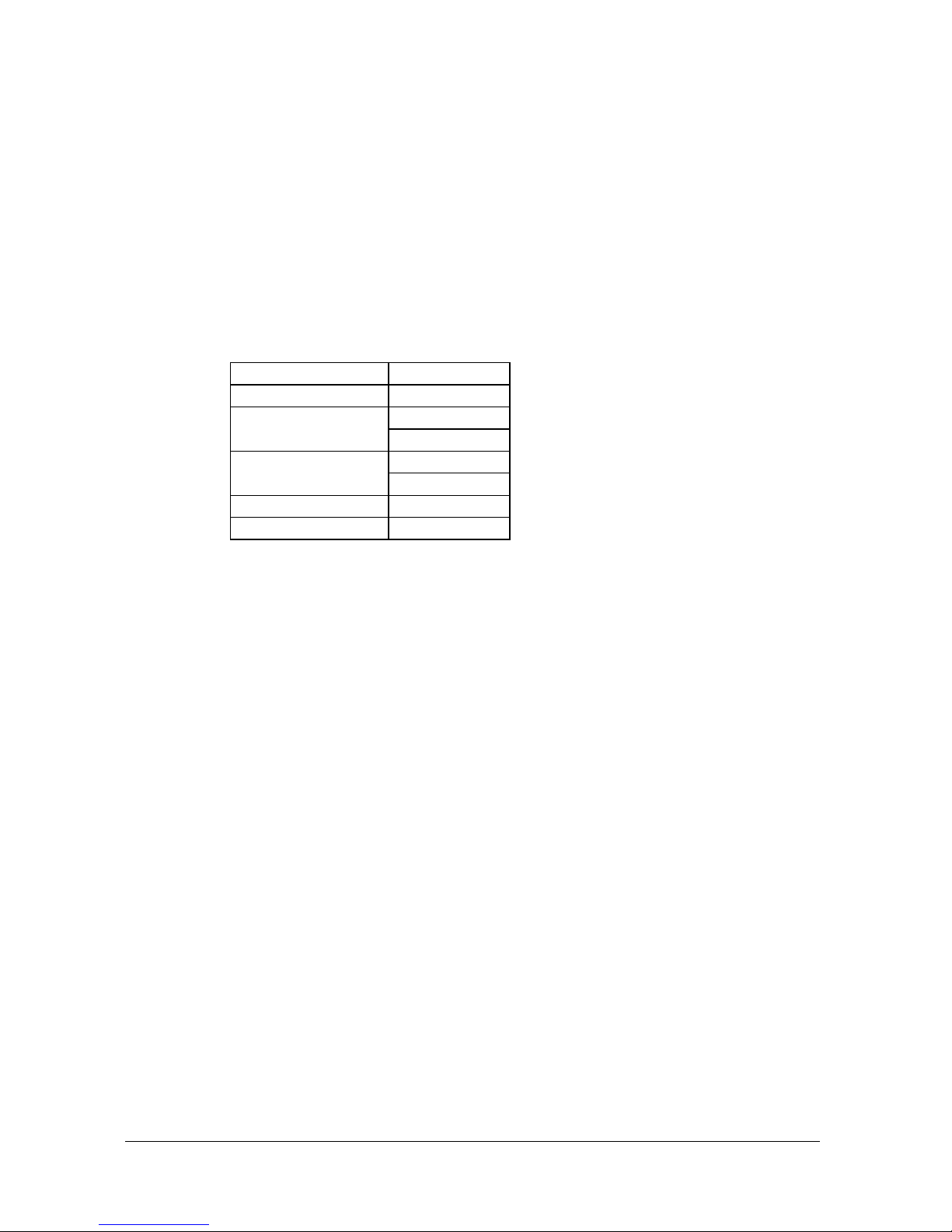
At most two EXP48 Expansion Modules of any type can be installed on top of the
MB48 motherboard except for both being EXP48 (0/16) or EXP48 (2/6), so that
MS48 system supports the following capacities :
Lines Extensions
4 28
18
6
34
24
8
40
10 30
12 36
The default numbering plan of MS48 system depends on the system capacity as
follows :
•
For capacities (4/12) and (6/18), the extensions have numbers 11 to 22
and 11 to 28, whereas the lines have numbers 01 to 04 and 01 to 06,
respectively.
•
For higher capacities, the extensions have three digit numbers, and the
numbering of the lines is similar to the lower capacities. So, the
extensions have numbers from 111 to 150 (max.) and the lines have
numbers from 01 to 12 (max.).
When all the modules are installed and the system is powered on, the system
checks and recognizes all the cards automatically and arranges the numbering
plan accordingly.
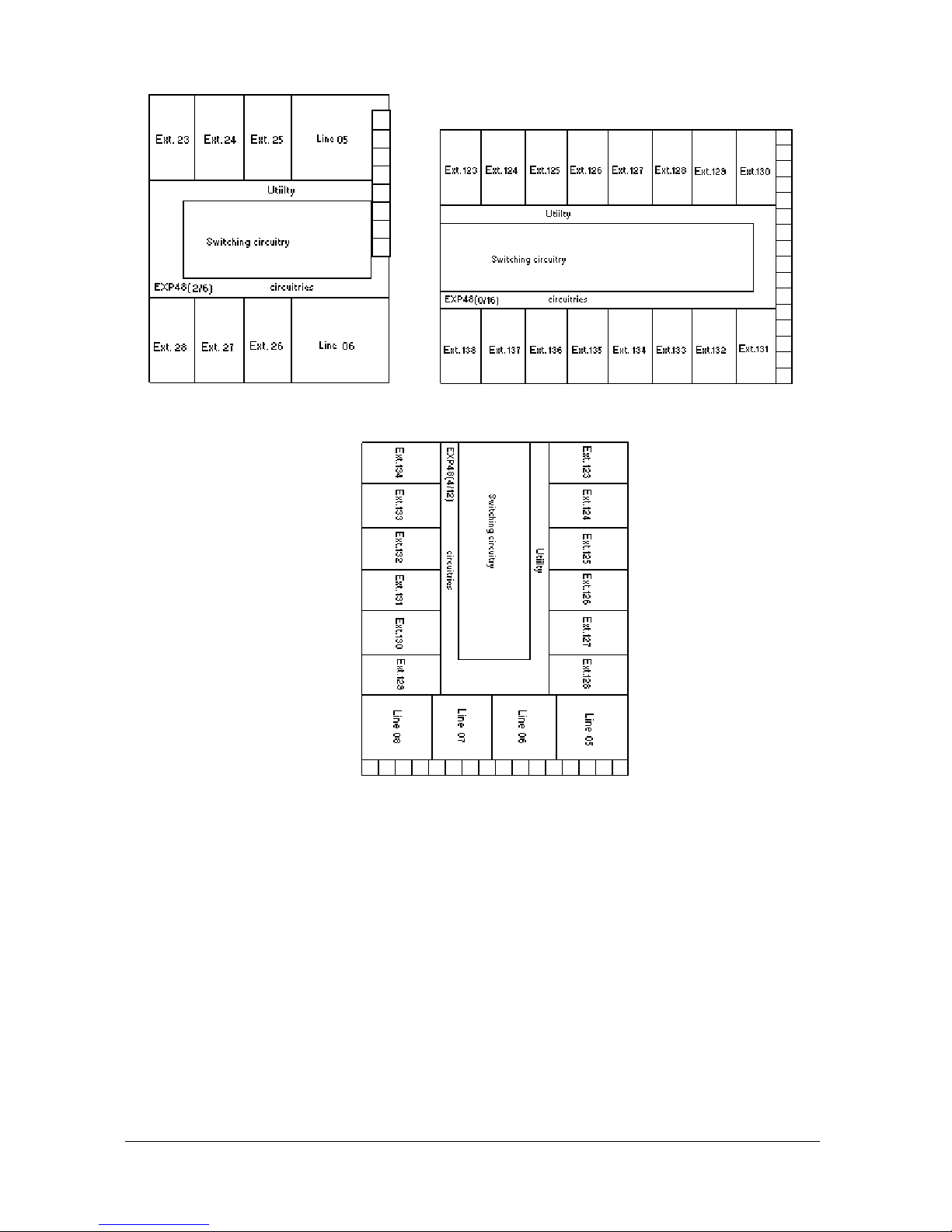
Other than the extension circuitries that exist on all EXP48 modules and the line
circuitries that exist on all EXP48 modules except for EXP48 (0/16), there are also
utility and switching circuitries on EXP48 Expansion Modules. See the following
figures for the location of these circuitries, noting that the extension and line
numbers are assigned with the assumption that the related EXP48 module is the
first card installed on top of the MB48 motherboard.
Karel MS48 Installation & Maintenance Guide
Edition 3.2
7
Figure A-5.I Figure A-5.II
Figure A-5.III
As explained above, the DTMF circuitries exist on the MB48 motherboard, but not
on the EXP48 modules. However, when the system capacity is increased beyond
6/18, the MF receiver capacity of the MB48 motherboard - that can serve 8 ports at
a time - may be insufficient especially under heavy traffic. The MFR48 MF-Receiver
Card that comes with each EXP48 (0/16) and EXP48 (4/12) module is designed to
avoid such cases. MFR48 is to be installed on top of the MB48 motherboard when
at least one of the two expansion modules is to be used. The MFR48 card has 2
MF receiver chips and thus increments the MF receiver capacity of the system by
serving 4 extra ports at a time.
The dimensions of MB48 are 19 cm x 35 cm and the weight is 0.75 kg.
The dimensions of EXP48 (4/12) are 18.5 cm x 26 cm and the weight is 0.6 kg.
The dimensions of EXP48 (0/16) are 18.5 cm x 23 cm and the weight is 0.4 kg.
The dimensions of EXP48 (2/6) are 14.5 cm x 16.5 cm and the weight is 0.3 kg.
Karel MS48 Installation & Maintenance Guide
Edition 3.2
8
I.2. POWER TO THE SYSTEM
MS48 system receives 220 VAC from the mains. Inside the fuse slot next to the
system ON/OFF switch, there exists a F-type fuse of 1 A / 250 VAC for the first step
protection.
The system can operate for the mains input of 180 - 260 VAC 50/60 Hz. The
PWT48 Power Transformer generates 2x15 VAC from the mains voltage, which is
processed by the SPS48 Power Supply Module.
The PWT48 Power Transformer is located inside a metal cage at the up left corner
of the CBN48 cabinet, together with the RNT48 Ring Transformer which generates
64 Vrms ring signal.
I.2.A. SPS48 POWER SUPPLY MODULE
SPS48 Power Supply Module is simply a card that resides below the metal cage
surrounding the RNT48 and PWT48 transformers.
SPS48 is a Switched Mode Power Supply (SMPS). Receiving 2x15 VAC from the
PWT48 Power Transformer, SPS48 generates +5 VDC, +12 VDC and -24 VDC for
the system operation, for the accessories and for the RNT48 Ring Transformer.
The output of the RNT48 transformer is the 64Vrms ring signal, which is transferred
to the MB48 motherboard directly.
SPS48 also has connectors for KY16 Mini Printer and OP48(-H) Consoles /
LT48(-H) Feature Phones / PG100 Local Pager / IA12 ISDN Adaptor. The Busy and
Data signals on these connectors are not processed by SPS48, they are just
received from the MB48 motherboard so as to be transmitted to the accessories.
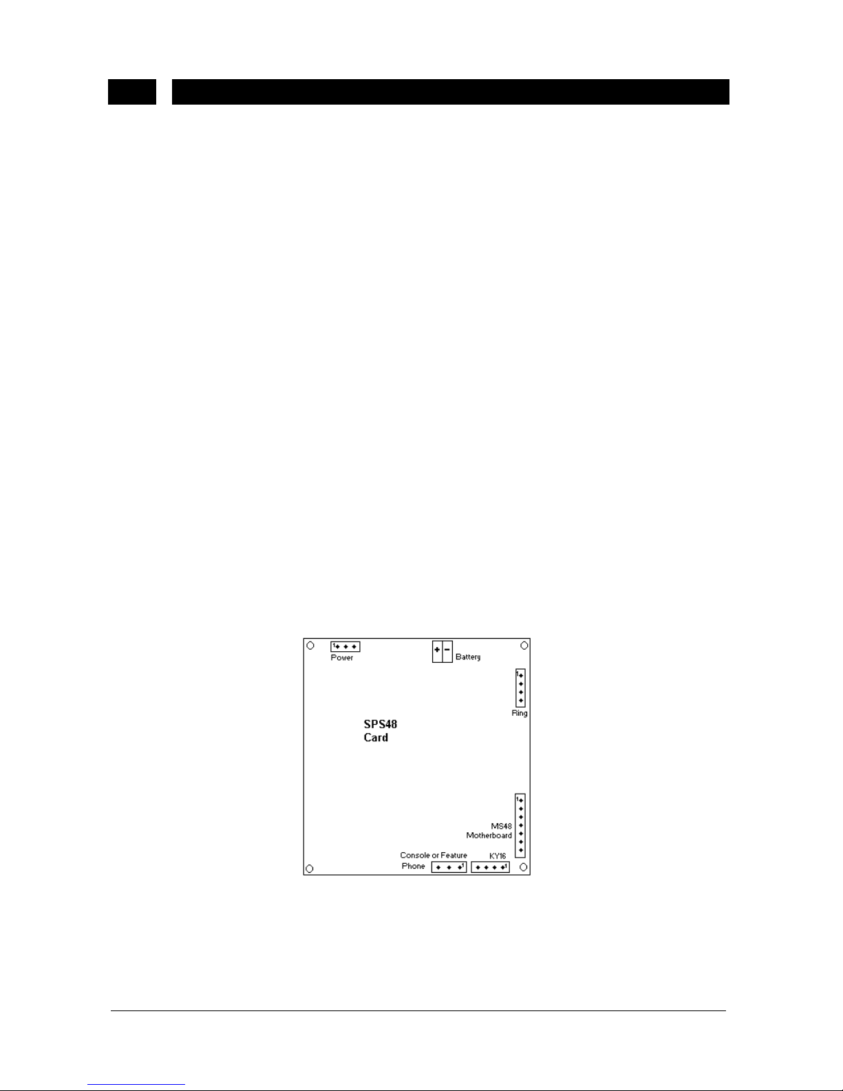
See the following figure for the location of the connectors on SPS48.
Figure A-6
The pin-out of the connectors on SPS48 module are illustrated in the following
table:
Karel MS48 Installation & Maintenance Guide
Edition 3.2
9
SPS48 – MB48 Connector SPS48 – RNT48 Connector
Pin Signal Pin Voltage
1 Ring Control 1 2 Buzzer Control 2 GND
3 - 24 VDC 3 -24 VDC
4 + 5 VDC 4 +24 VDC
5 Data
6 GND SPS48 - KY16 Connect or
7 Busy Pin Signal
1 GND
SPS48 – PWT48 Connector 2 Data
Between Pins Voltage 3 Busy
1 & 3 15.5 VAC 4 2 & 3 15.5 VAC
SPS48 - Console/Feat ure P hone/Pager/ ISDN Adaptor Connect or
Pin Signal
1 Data
2 +12 VDC
3 GND
MS48 system can be backed up with a battery of 12 VDC in order to provide the
continuity of the operation in case of mains failure, by the help of the battery
backup circuitries of SPS48. For the cases where a battery is to be connected to
the system, it is strongly recommended to choose a dry battery for the proper
operation.
The MS48 system that is equipped with a 12 V – 7 Ah battery can continue to run
for 5 hours under an average traffic of 35 %.
There exists a connector on the SPS48 card for battery connection (see Figure
A-6). The F-Type fuse of 8 A / 12 VDC for battery is also available on SPS48 card,
residing at the down right corner of the power connector.
SPS48 is also capable of charging the battery while the system power is on and the
system is running under low traffic. Besides, there exists a low voltage battery cutoff circuitry, which turns itself off when the battery voltage goes below 8.5 VDC and
does not start until the battery voltage is above 11.5 VDC. So, preventing full
discharge of the battery SPS48 makes the lifetime of the battery longer.
The SPS48 card also has the system buzzer that may be used as an external
ringer for the incoming external calls.
The dimensions of the SPS48 card are 11 cm x 11.5 cm and the weight is 0.3 kg.
Karel MS48 Installation & Maintenance Guide
Edition 3.2
10
I.2.B. POWER FAILURE TRANSFER STATIONS
In case of power failure the stand-by battery backup allows the system resume
operation without any interrupt.
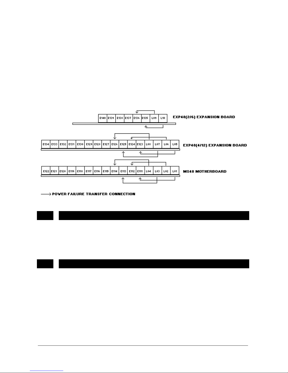
In case there is no battery connected to the system when the power goes off, the
lines on the MB48 motherboard and EXP48 (4/12) module are automatically
connected to first 4 extensions of the same board. The same also applies to EXP48
(2/6), such that the lines on EXP48 (2/6) module are connected to the first 2
extensions of the same board, in case of power failure.
See the following figure illustrating the power failure transfer stations of MS48
(10/30) system.
Figure A-7
I.3. EXTERNAL MUSIC CONNECTOR
Any external music source (tape recorder, radio or CD player) can be connected to
the system to be used for background music facility and to be transmitted to the
external parties parked or put on hold. This connection is established via the 2-pin
music connector on the MB48 motherboard.
I.4. EXTERNAL RELAY
An external relay which is rated for 250 VAC - 24 VDC at a maximum current of 2 A
exists on the MB48 motherboard to be used to activate either a door opener, an
external ringer, an external music source or an external announcement system.
The connection to the external relay is established through the 2-pin relay
connector on the MB48 motherboard. The selection among these devices is made
by programming.
Karel MS48 Installation & Maintenance Guide
Edition 3.2
11
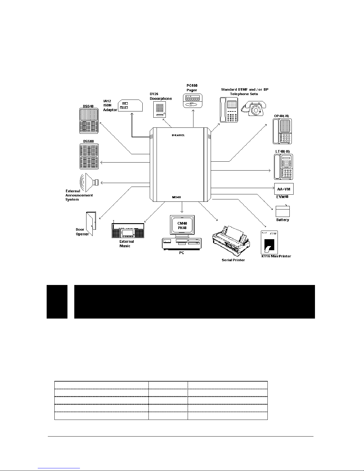
II. ACCESSORIES
To offer you a full telecommunication system, MS48 is equipped with many
accessories. These accessories are shown in the following figure and explained
one by one in the following sections.
Figure A-8
II.1. CONSOLES, FEATURE PHONES,
DIRECT STATION SELECT MODULES –
OP48(-H), LT48(-H), DSS80, DSS40
OP48(-H) Consoles, LT48(-H) Feature Phones, DSS80 / DSS40 Direct Station
Select Modules are the members of the same telephone family, hence they have
similar cases.
The data cabling of these sets is made via the 3-pin CONSOLE connector on the
SPS48 Power Supply Module. The signaling between the system and consoles,
feature phones or DSS modules is illustrated in the following table.
SPS48 Card Telephone / DSS Card
CONSOLE Connector Pin No Signal RJ Socket P i n No
1 Data 1
2 + 12 VDC 6
3 GND 2
The input of +12 VDC is regulated to +5 VDC by telephone / DSS cards.
Karel MS48 Installation & Maintenance Guide
Edition 3.2
12
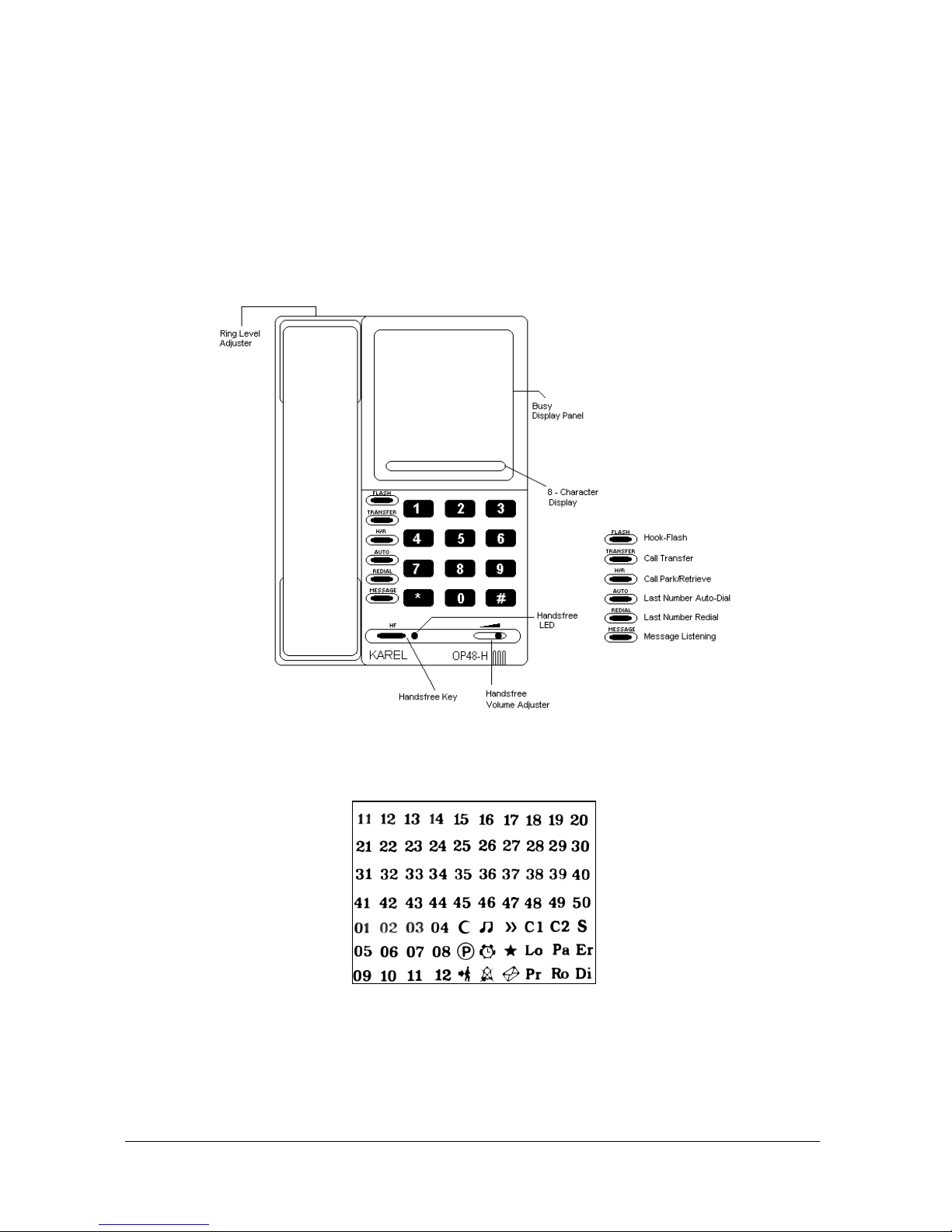
II.1.A. OP48(-H) CONSOLE
There are two types of OP48 Consoles, OP48 Console and OP48-H Handsfree
Console, the second one being half-duplex. The OP48(-H) Console has a BDP
(Busy Display Panel) that shows the states of all the extensions and lines as well
as some system features. There is also an 8-Character Display that keeps the user
informed about the calling / called extension and dialed numbers as well as some
system features.
The outlook and BDP of OP48-H are illustrated in the following figures.
Handsfree Key, Handsfree Volume Adjuster and Handsfree LED are available only on the handsfree versions.
Figure A-9
Figure A-10
The dimensions of OP48(-H) are 22 cm x 6.5 cm x 16 cm and the weight is 0.9 kg.
Karel MS48 Installation & Maintenance Guide
Edition 3.2
13
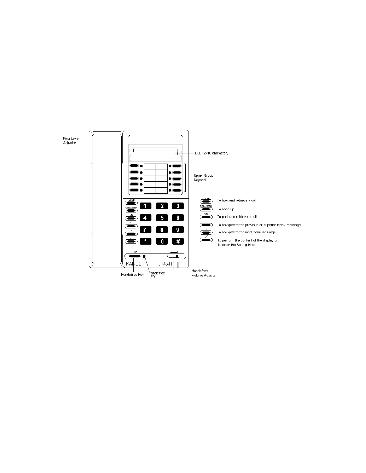
II.1.B. LT48(-H) FEATURE PHONE
There are two types of LT48 Feature Phones, LT48 Feature Phone and LT48-H
Handsfree Feature Phone, the second one being half-duplex. The LT48(-H)
Feature Phone is equipped with a 2 x 16 menu driven LCD, which offers self
explanatory messages for the user to monitor the state of the operation and access
many system features. Also, it is possible to make one touch dialing for accessing
any extension / line or activating most system features, by the help of the 10
programmable keys in the upper keypad.
The outlook of LT48-H is illustrated in the following figure.
Handsfree Key, Handsfree Volume Adjuster and Handsfree LED are available only on the handsfree versions.
Figure A-11
The dimensions of LT48(-H) are 22 cm x 6.5 cm x 16 cm and the weight is 0.9 kg.
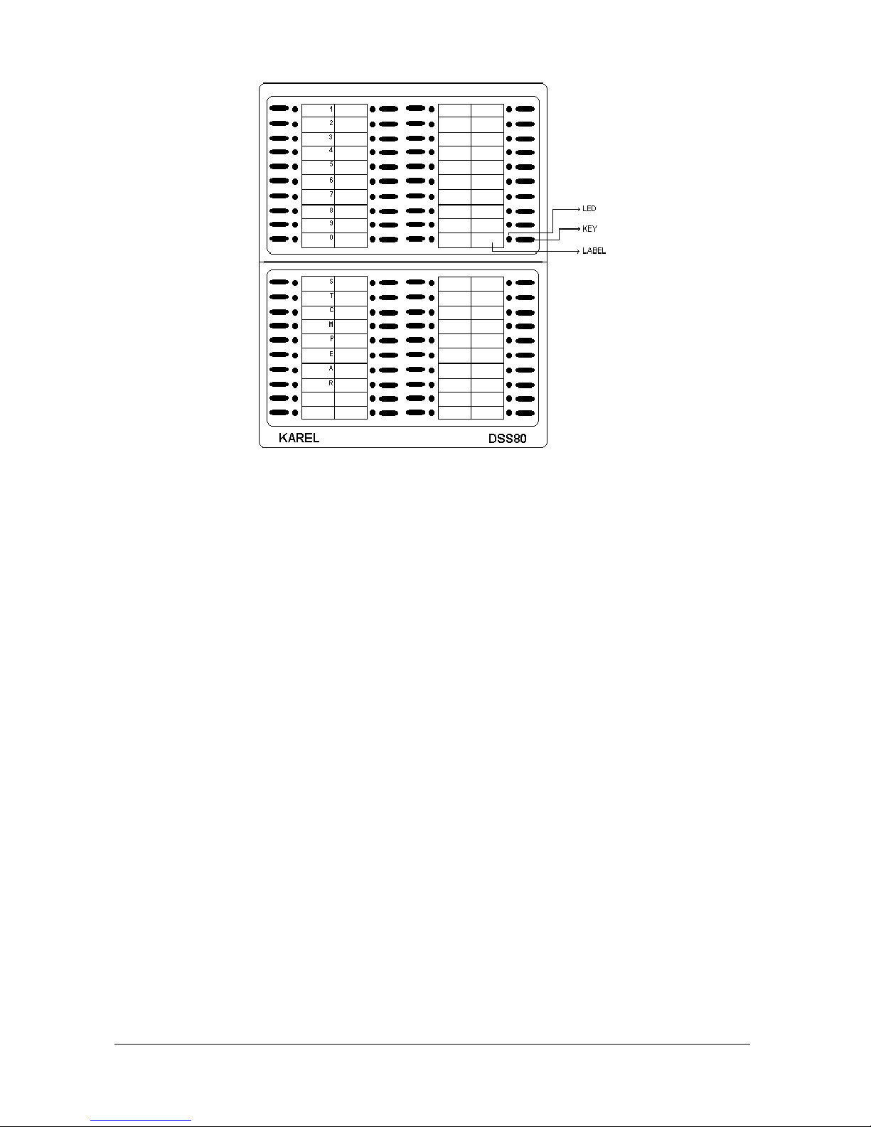
II.1.C. DSS80 DIRECT STATION SELECT MODULE
The DSS80 Direct Station Select Module, which is used as an add-on module for
OP48(-H) Consoles and LT48(-H) Feature Phones, is a programmable keypad,
including 80 multipurpose keys and 80 corresponding LEDs.
Each key may be programmed to activate two facilities, which may be calling an
extension, accessing a line or activating a system feature. The corresponding LED
of each key shows the status of the facility assigned to the primary function of the
key.
The outlook of DSS80 is illustrated in the following figure.
Karel MS48 Installation & Maintenance Guide
Edition 3.2
14
Figure A-12
The dimensions of DSS80 are 16 cm x 22 cm x 6.5 cm and the weight is 0.7 kg.
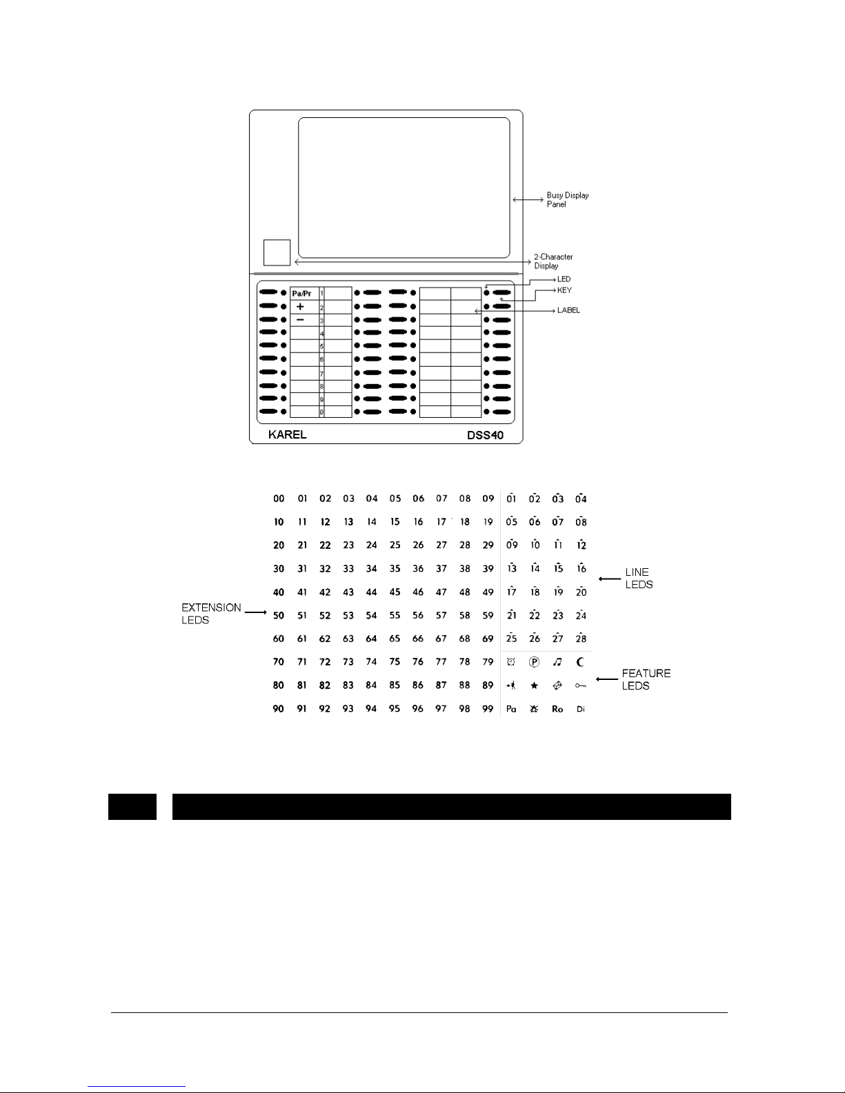
II.1.D. DSS40 DIRECT STATION SELECT MODULE
The DSS40 Direct Station Select Module, which is used as an add-on module for
OP48(-H) Consoles and LT48(-H) Feature Phones, consists of a BDP (Busy
Display Panel), a 2-Character Display and a programmable keypad including 40
multipurpose keys and 40 corresponding LEDs.
Each key may be programmed to activate two facilities, which may be calling an
extension, accessing a line or activating a system feature. The corresponding LED
of each key shows the status of the facility assigned to the primary function of the
key.
The BDP (Busy Display Panel) together with the 2-Character Display shows the
states of 40 extensions and 12 lines as well as some system features.
DSS40 can be used not only with the MS48 system, but also with the other KAREL
systems of bigger capacities. That is why DSS40 handles 4-digit physical numbers
for extensions, such that the 2-Character Display is used to show the most
significant two digits whereas the LEDs on the BDP are used to indicate the least
significant two digits. In this way, the two digits in the 2-Character Display may be
interpreted as “page numbers”, and there are 3 pages with numbers 11 to 13 that
covers all the extensions in the KAREL systems to which DSS40 can be
connected. It is also possible to navigate forward and backward among the pages,
via the “+” and “-“ keys on DSS40 keypad. However, when DSS40 is connected to
MS48 system, it is enough to observe the first page (page 11) covering the
extensions 1111 to 1150. The states of 12 lines as well as system features are
displayed on all pages.
Karel MS48 Installation & Maintenance Guide
Edition 3.2
15
The outlook and BDP of DSS40 are illustrated in the following figures.
Figure A-13
Figure A-14
The dimensions of the DSS40 are 16 cm x 22 cm x 6.5 cm and the weight is 0.7 kg.
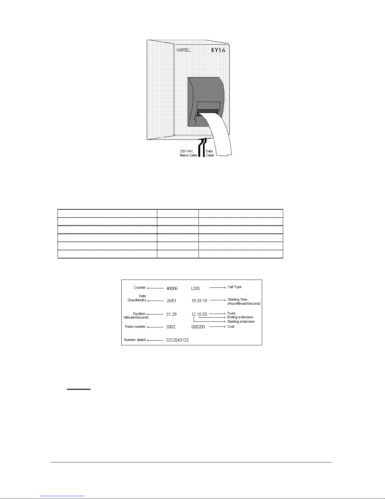
II.2. MINI PRINTER - KY16
MS48 system offers
Call Record Lis ting (CRL)
facilities, by keeping the records of
the external calls and storing them in its non-volatile memory against any power
failure. You may obtain these records by way of some external devices.
One of these external devices is KY16 Mini Printer, which gives 16-column printout
using an Epson type print head.
The following figure illustrates the outlook of KY16 Mini Printer.
Karel MS48 Installation & Maintenance Guide
Edition 3.2
16
Figure A-15
The data cabling of KY16 Mini Printer is made via the 4-pin PRINTER connector on
SPS48 Power Supply Module. The signaling between the system and KY16 is
illustrated in the following table.
SPS48 Card KY16 Card
PRINTER Connector Pin No Signal Connector Pin No
1 - 2 Busy 2
3 Data 3
4 GND 1
Below is a sample printout of a call record obtained from a KY16.
Figure A-16
The dimensions of KY16 are 15 cm x 20.5 cm x 9 cm and the weight is 1.3 kg.
•
N
OTE
Only one of the three CRL accessories - namely KY16 Mini Printer, CM48 CRL
Interface and/or PK48 PC-Console Interface, RS232 Serial Printer Interface can be connected to the system at a time. The selection among these devices
is made by programming.
Karel MS48 Installation & Maintenance Guide
Edition 3.2
17
II.3. CALL RECORD LISTING INTERFACE – CM48
MS48 system offers the alternative of using a PC for
Call Record Listing (CRL)
facilities, so that you can process the records of the external calls stored in the
system memory over PC.
CM48 Call Record Listing Interface serves this purpose. By way of CM48, call
records can be processed, filtered and statistically ordered or a phone directory
can be created. CM48 consists of the add-on card called PKCR, a 5-meter cable
for PC-PKCR connection, a security plug and a 3.5” diskette with the necessary
software that operates under Windows. The cable has a 25-pin D-type plug at the
PC end and a 5-pin connector at the PKCR end.
•
PC R
EQUIREMENTS
:
The PC to be used with MS48 should have the following specifications:
a) 640 KB RAM (at least)
b) Windows (not older than 3.1)
c) A harddisk
d) A serial port
•
S
IGNALING AND COMMUNICATION PARAMETERS
:
The signaling between PKCR card and the PC is illustrated in the following
table. Since the PC-PKCR cable has a 25-pin plug at the PC end, it is
necessary to employ a 25-pin to 9-pin converter plug, in order to use the 9-pin
connector of the PC:
PKCR Card PC
Connector Pin No Signal 25-pin Connector
Pin No
9-pin Connector
Pin No
1 + 10 VDC 4 7
2 - 10 VDC 20 4
3 TXD 3 2
4 RXD 2 3
5 PC GND 7 5
The signal names above are given with respect to CM48 and these pin
assignments are valid only for IBM compatible devices. If your device is not
IBM compatible, then you must provide the requested pin connections to
match the signaling parameters of CM48.
The communication protocol for PC-Exchange connection is illustrated in the
following table.
For PC
Data Bits 8
Stop Bit 1
Parity None
Baud Rate 4800 Bps
CM48 is able to set the communication protocol to the appropriate values
automatically.
Karel MS48 Installation & Maintenance Guide
Edition 3.2
18
•
D
ATA FORMAT OF
CM48:
A call record consists of two lines, each followed by Carriage return (0Dh) and
Line Feed (0Ah) characters.
Structure of the first line:
Starting Character Position Field Width Information
1 1 #; indicates start of record
2 4 4 digit counter value
6 1 Space
7 4 or 2 Call type
11 1 Space
12 1 Common Pool information
- Call type:
LDIS Long Distance
INTL International
IC Incoming
Call type field and the preceeding space are not sent to PC for local calls.
- Common pool information field contains the character C to indicate calls
made from the common pool. If the call was not made from the common
pool then this field and the preceding space are not sent to PC.
Structure of the second line:
Starting Character
Position
Field
Width
Information
1 8 Date in the format dd/mm/yy
9 1 Space
10 8 Starting time of the call in the format hh:mm:ss
18 1 Space
19 8 Ending time of the call in the format hh:mm:ss
27 1 Space
28 5 Call duration in the format mm:ss
33 1 Space
34 4 Starting extension number, OPE for the
operator and Dtt for the incoming calls coming
from a DISA line where tt is the line number.
38 1 Space
39 4 Ending extension number, OPE for the
operator.
43 1 Space
44 3 Call Info
47 1 Space
48 2 Line number
50 1 Space
 Loading...