

Karel MS224 Installation & Maintenance Manual

Karel MS224
Telephone System
Installation
&
Maintenance
Guide
Edition 3.2

i
CONTENTS
SECTION
PAGE
INTRODUCTION 1
TECHNICAL REFERENCE
I. SYSTEM 3
I.1. PARTS LIST 4
I.2. BACKPLANE OF THE S Y S T EM – BPL224 6
I.3. POWER TO THE SYSTEM 7
I.3.A. POWER SUPPLY MODULE – S PS224 7
I.4. CENTRAL PROCESSING MODULE – CPU224 &
CPU CONNECTION CARD - MS224 CPUKON
9
I.5. EXPANSION MODULES - MS224 EX1 / MS224 EX2 13
I.6. EXTERNAL MUSIC CONNECTOR 19
I.7. EXTERNAL RELAY 19
II. ACCESSORIES 21
II.1. CONSOLES, FEATURE PHONES, DIRECT STATION SELECT
MODULES - OP48(-H), LT48(-H), DSS80, DSS40
22
II.1.A. OP48(-H) CONSOLE 22
II.1.B. LT48(-H) FEATURE PHONE 23
II.1.C. DSS80 DIRECT STAT ION SELECT MODULE 24
II.1.D. DSS40 DIRECT STAT ION SELECT MODULE 25
II.2. SERIAL INTERFACE – CM224, PK224, CM224+PK224, SERIAL
PRINTER INTERFACE
26
II.2.A. CM224 CALL RECORD LISTING INTERFACE AND/OR
PK224 PC-CONSOLE INTERFACE 26
II.2.B. SERIAL PRINTER INTERFACE 29
II.3. DOORPHONE – DY01 30
II.4. EXTERNAL ANNOUNCEMENT SYSTEM 31
II.5. AUTO ATTENDANT & VOICE MAI L – E V M224 31
II.6. ISDN ADAPTOR – IA12, EXP-IA12 32
II.7. LOCAL PAGER – PG100 35
II.8. STANDARD TELEPHONE SETS 36
II.9. FILTER & PROTECTION UNIT – FPBASE, FPEXP 37
III. SOFTWARE 39
IV. TECHNICAL SPECIFICATIONS 41

ii
SECTION
PAGE
INSTALLATION
I. PRELIMINARY NOTICE 43
I.1. DELIVERY CHECK 43
I.2. INSPECTION 43
I.3. ENVIRONMENTAL REQUIREMENTS 43
II. SYSTEM INSTALLATION 45
II.1. GROUNDING 46
II.2. POWER SUPPLY MODULE 47
II.3. CENTRAL PROCESSING MODULE 48
II.4. EXPANSION MODULES 50
III. ACCESSORY INSTALLATION 53
III.1. CONSOLES, FEATURE PHONES, DIRECT STATION SELECT
MODULES
53
III.2. SERIAL INTERFACE 58
III.2.A. PC INTERFACE
58
III.2.B. SERIAL PRINTER INTERFACE 59
III.3. DOORPHONE 60
III.4. E XTERNAL A NNOUNCEMENT SYSTEM 62
III.5. ISDN ADAPTOR 63
III.6. AUTO ATTENDANT & VOICE MAIL 67
III.7. LOCAL PAGER 68
III.8. STA NDA RD TELEPHONE SETS, E XTERNAL LINES 72
III.9. FILTER & P ROTECTI ON UNI T 73
III.10. EXTERNAL MUSIC SOURCE 74
III.11. EXTERNAL RELAY 75
MAINTENANCE
I. MAINTAINING THE SYSTEM 77

INTRODUCTION
This Installation and Maintenance G uide provides an overall technical
reference on the KAREL MS224 system and its accessories and
includes descriptions, structures and capabilities as well as the
installation and maintenance information.
This guide is formed up of three main chapters:
1) Technical Reference: The system outline is given and all the
accessories are described. Brief information about the software
structure of the system is presented and finally the technical
specifications of the system are listed.
2) Installation Guide: The basic system installation and wiring
instructions are presented. Follow ing the system installation p art,
the installation and wiring of the accessories are explained.
3) Maintenance Guide: The basic steps to solve the problems faced
after the installation of the system are given.

Karel MS224 Installation & Maintenance Guide
Edition 3.2
3
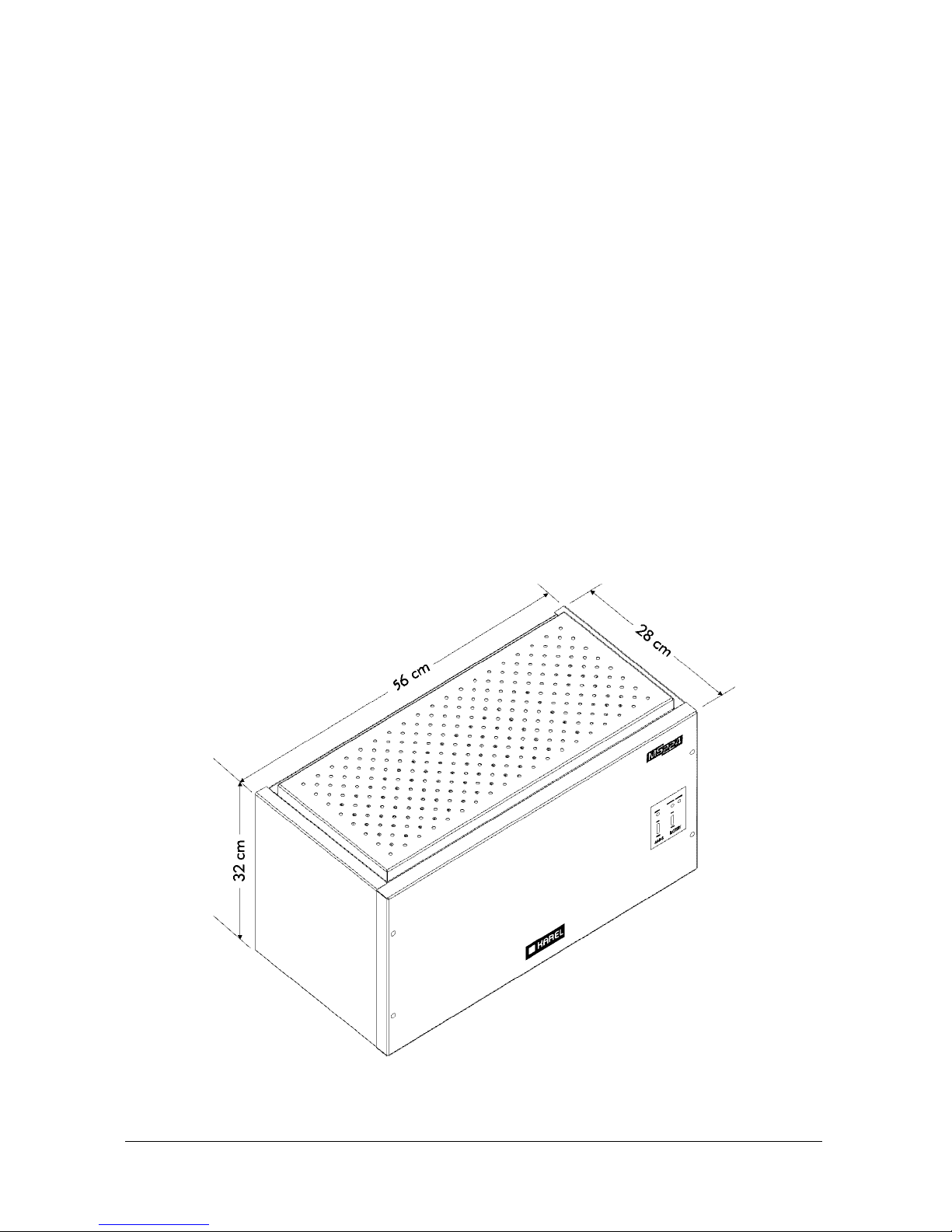
I. SYSTEM
MS224 system has a capacity of 4 to 28 lines and 12 to 200 extensions.
At minimum capacity, the MS224 system consists of the following parts :
•
CBN224 Cabinet made of metal, including a metal rack and some plastic parts,
•
SPS224 Power Supply Module including a metal power rack, a power card and
a ring transformer,
•
BPL224 Backplane,
•
CPU224 Central Processing Module,
•
MS224 EX1 (4/12) Expansion Module that can support the minimum capacity
of 4/12.
The MS224 system has 14 slots for MS224 EX1 (4/12) and MS224 EX2 (0/16)
Expansion Modules, and the maximum capacities that can be reached when all
slots are occupied are 24/200 and 28/196.
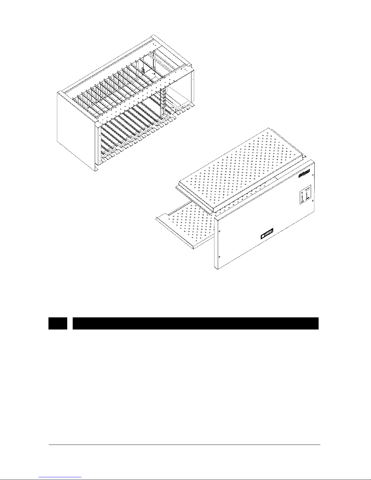
See the following figures to have a general idea about the outlook of the system
and the structure of the system cabinet.
Figure A-1
Karel MS224 Installation & Maintenance Guide
Edition 3.2
4
Figure A-2
The CBN224 metal cabinet provides a strong shell and a natural electromagnetic
shield for the system.
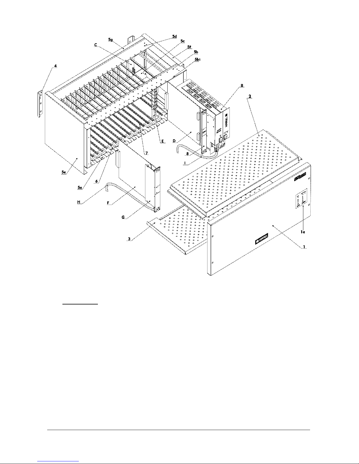
I.1. PARTS LIST
In order to make the reader familiar with the cabinet which has a complex structure,
the parts list for the cabinet is given below with respect to the references in the
following figure.
Karel MS224 Installation & Maintenance Guide
Edition 3.2
5
Figure A-3
A. CABINET
Metal Parts
1. Front Cover
1a. Power Info Panel
2. Top Cover
3. Bottom Cover
4. Wall Mount Bar
5. Rack
5a. Bottom Front Part
5b. Top Front Part
5b1. SPS224 Fixing Screw

Karel MS224 Installation & Maintenance Guide
Edition 3.2
6
5c. Bottom Rear Part
5d. Top Rear Part
5e. Left Cover
5f. Right Cover
5g. Rear Cover
6. Ground Contact Spring
Plastic Parts
7. Card Slot
8. Card Front Cover
B. SPS224 Power Supply Module
C. BPL224 Backplane
D. CPU224 Central Processing Board
E. MS224 CPUKON CPU Connection Card
F. MS224 EX1 (4/12) or MS224 EX2 (0/16) Expansion Module
G. CON1 EX1 Connection Card or CON2 EX2 Connection Card
H. CBL-16 16-Pair MDF Cable
I. Mains Cable
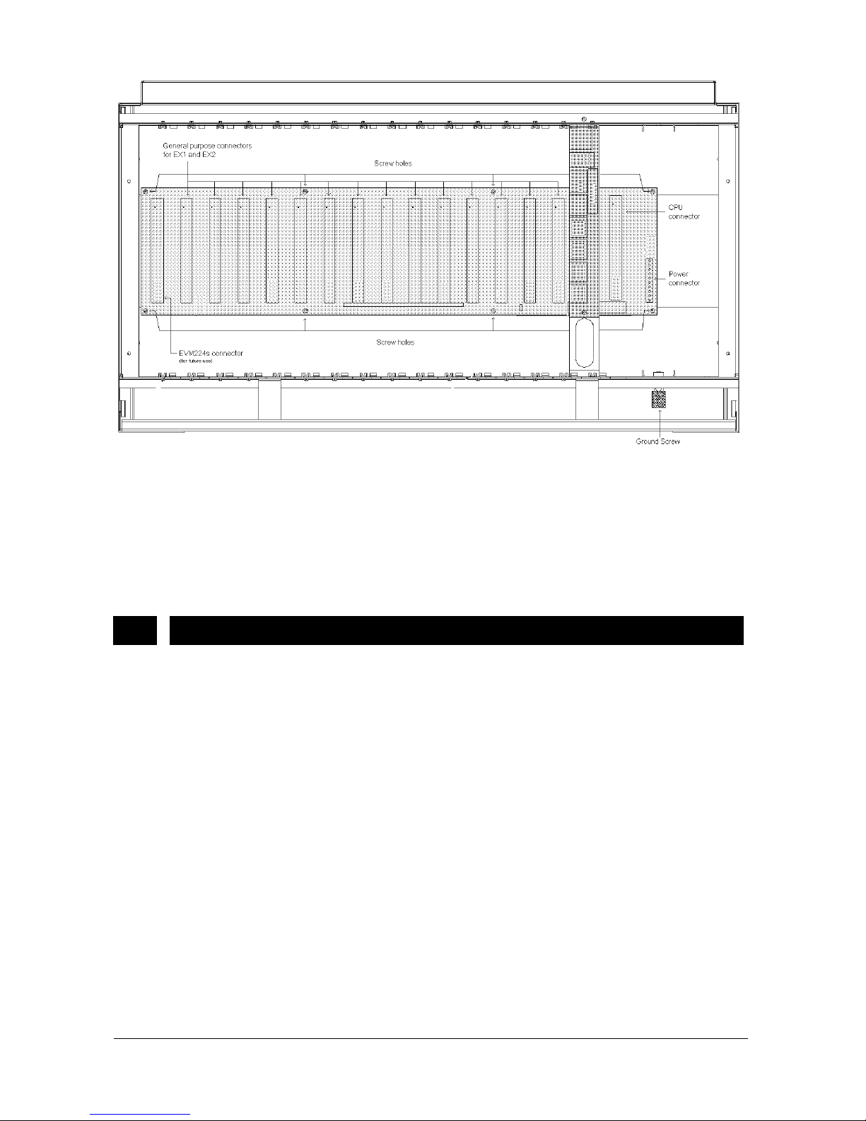
I.2. BACKPLANE OF THE SYSTEM – BPL224
The backbone of MS224 system is the BPL224 Backplane. All the modules, which
are SPS224, CPU224, MS224 EX1 and MS224 EX2, are linked through the
backplane.
BPL224 has the following connectors, from right to left (see Figure A-4):
•
One 10-pin male connector for SPS224 Power Supply,
•
One 96-pin female connector for CPU224 Central Processing Board,
•
Fourteen 96-pin female connectors for the common use of MS224 EX1
and MS224 EX2 Expansion Modules,
•
One 96-pin female connector for EVM224s Auto Attendant (reserved for
future use).
Karel MS224 Installation & Maintenance Guide
Edition 3.2
7
Figure A-4
BPL224 is mounted inside the metal rack between the top and bottom rear parts.
The connectors on BPL224 match the card slots on the metal cabinet to ease the
attachment of the modules.
The dimensions of BPL224 are 47 cm x 11 cm and the weight is 0.4 kg.
I.3. POWER TO THE SYSTEM
MS224 system receives 220 VAC from the mains. Inside the mains fuse slot on
SPS128 Power Supply Module, there exist two T-type fuses for mains - one on
phase and the other on neutral -
of 2 A / 250 VAC for the first step protection (see
Figure A-5).
The system can operate for the mains input of 180 - 260 VAC 50/60 Hz, which is
processed by the SPS224 Power Supply Module.
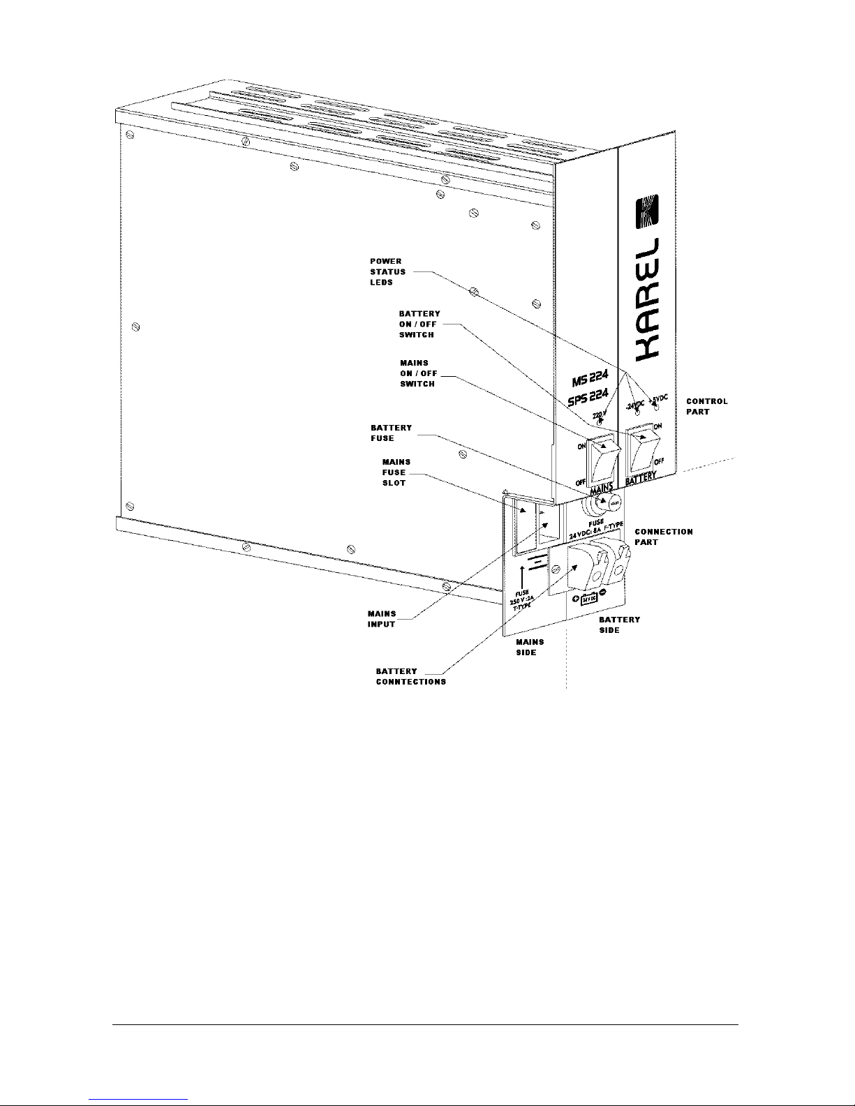
I.3.A. POWER SUPPLY MODULE - SPS224
The outlook of SPS224 Power Supply Module is illustrated in the following figure :
Karel MS224 Installation & Maintenance Guide
Edition 3.2
8
Figure A-5
SPS224 Power Supply Module is attached to the 10-pin power connector on the
BPL224 Backplane (see Figure A-4) and fixed to the top front part of the metal
rack by a screw (see Figure A-3).
SPS224 Power Supply Module consists of a metal power rack, to which the
SPS224CR Power Card and the ring transformer are fastened. The mains
transformer is located on the SPS224CR Power Card.
SPS224 is a Switched Mode Power Supply (SMPS) operating at mains voltage.
Receiving 220 VAC over the mains, SPS224CR generates 5 VDC, -5 VDC, +12
VDC and -24 VDC for the system operation, for the accessories and for the ring
transformer. The ring transformer generates the 64 Vrms ring signal. Through the
10-pin power connector, the outputs of SPS224CR and ring transformer are
passed to the BPL224 Backplane, which carries them to the system modules. The
pin-out of the SPS224 – BPL224 connector on the backplane is as follows:

Karel MS224 Installation & Maintenance Guide
Edition 3.2
9
SPS224 – BPL224 Connector
Pin Signal Pin Signal
1 - 24 VDC 6 GNDCPU
2 GND 7 - 5 VDC
3 GND 8 GND
4 + 12 VDC 9 + 5 VDC
5 + 5 VCPU 10 64 Vrms (Ring)
MS224 system can be backed up with a battery of 24 VDC in order to provide the
continuity of the operation in case of mains failure. Hence, SPS224CR has
necessary circuitries for battery backup. It is strongly recommended to use a dry
battery for proper operation of the system, as the system does not have embedded
power failure transfer stations. Also a 24 V - 15 Ah battery is recommended for a
full capacity system with an average traffic of 35%.
There exists one F-type fuse of 8 A / 24 VDC for battery. The battery input is also
controlled by the battery ON/OFF switch, which enables the user to put the battery
out of service when necessary.
SPS224CR is also capable of charging the battery while the system power is on
and the system is running under low traffic. Besides, there exists a low voltage
battery cut-off circuitry, which turns itself off when the battery voltage goes below
17 VDC and does not start until the battery voltage is above 23 VDC. So,
preventing full discharge of the battery SPS224 makes the lifetime of the battery
longer.
The Power Status LEDs on the front panel of the SPS224 Power Supply Module
help to identify the power source in use on time. There are three LEDs. One is for
220 VAC and the others are for -24 VDC and +5 VDC. Normally when the system is
fed from the mains all three LEDs are on. The 220 VAC LED turns off when the
mains power is off. In this case - 24 VDC and + 5 VDC LEDs stay on, if battery
backup is available for the system.
Through the power info panel on the front cover of the system cabinet, it is possible
to access mains and battery ON/OFF switches or to observe the power status
LEDs, without opening the front cover.
The dimensions of the SPS224 are 8 cm x 25.5 cm x 25 cm and the weight is 3.1
kg (including SPS224CR).
The dimensions of the SPS224CR are 20 cm x 20.5 cm x 6 cm and the weight is
1.1 kg.
I.4. CENTRAL PROCESSING MODULE – CPU224 &
CPU CONNECTION CARD - MS224 CPUKON
CPU224 Central Processing Module is located on the rightmost plastic card slot
inside the cabinet. The board is attached to the CPU connector on the BPL224
Backplane (see Figure A-4) and fixed to the top and bottom front parts of the metal
rack via the locks on the plastic card cover.
Karel MS224 Installation & Maintenance Guide
Edition 3.2
10
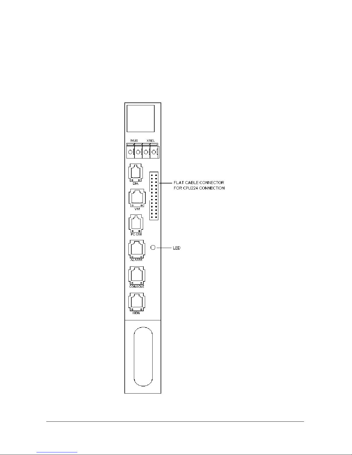
MS224 CPUKON CPU Connection Card resides next to CPU224. It is fixed to the
top and bottom front parts of the metal rack by screws and connected to the
CPU224 board by a 26-pin flat cable, called MS224 CPU-FC. See Figure A-6 for
the outlook of MS224 CPUKON card.
There exists a plastic card cover in front of MS224 CPUKON card, which is fixed to
the top and bottom front parts of the metal rack via the the locks on the plastic card
cover, but not to MS224 CPUKON card itself. It is necssary to take out this cover
before accessing the connectors on MS224 CPUKON card.
* ALARM connector is reserved for future use.
Figure A-6
Karel MS224 Installation & Maintenance Guide
Edition 3.2
11
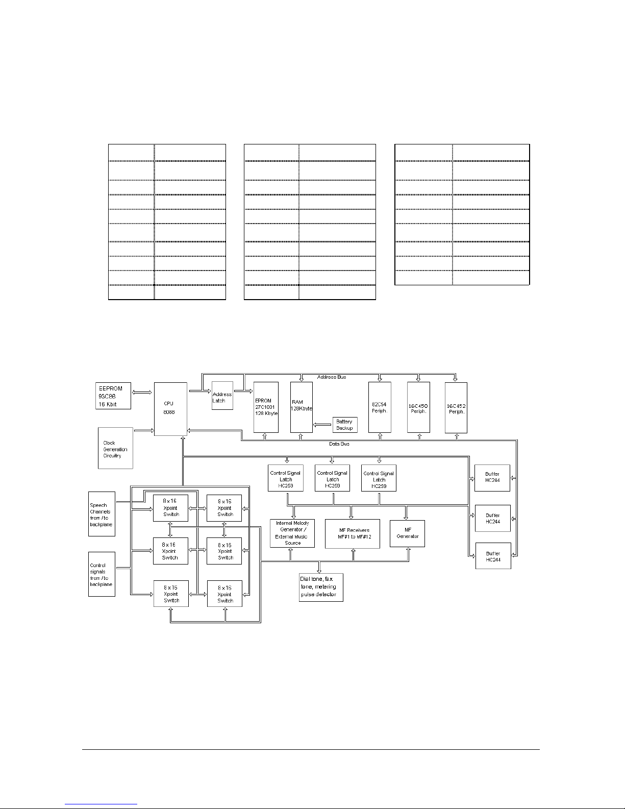
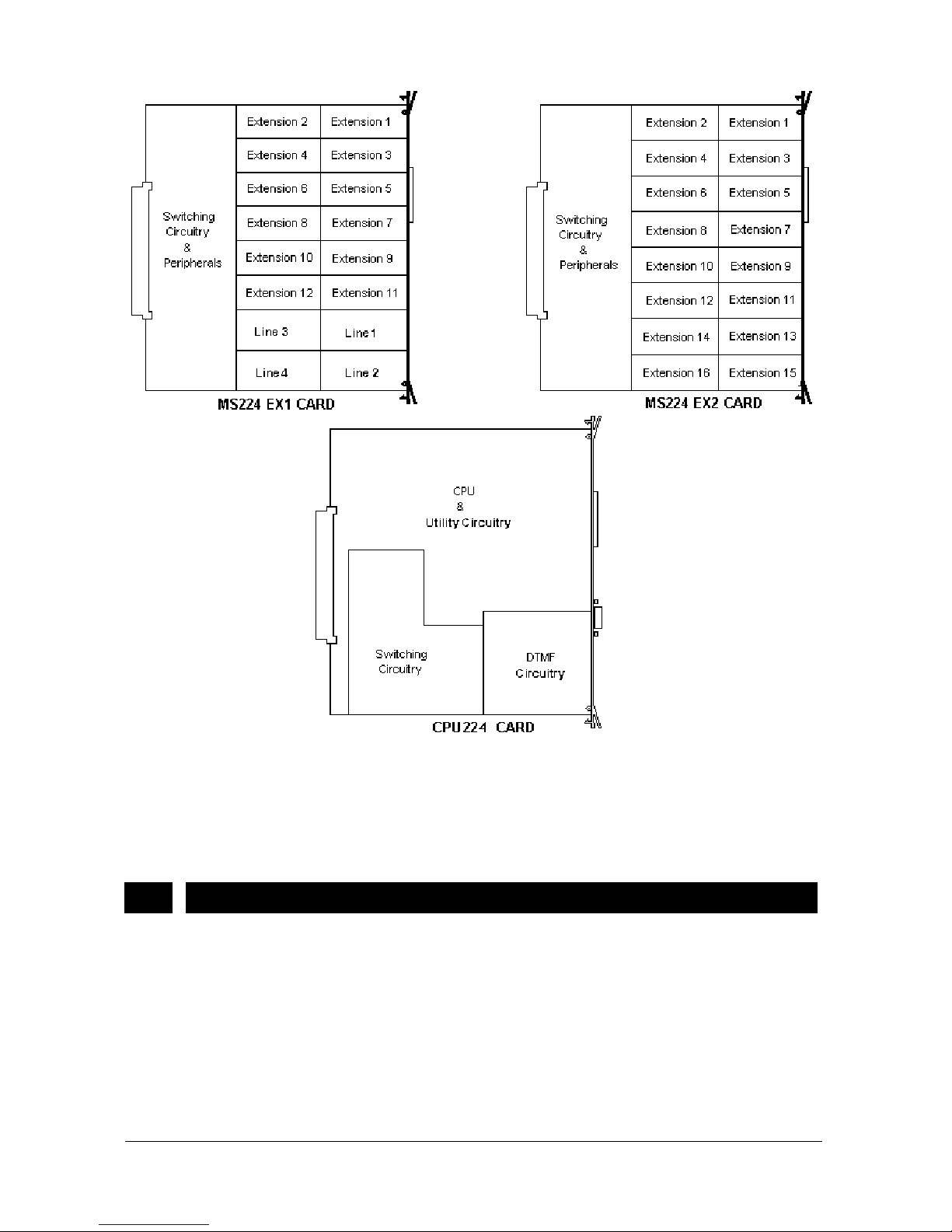
CPU224 is the brain of the system consisting of the microprocessor, utility,
switching and DTMF circuitries. See Figure A-8 for the location of these circuitries
and Figure A-7 for the operational flow diagram of CPU224.
MS224 CPUKON is the interface between the accessories and the system, it
includes the connectors used to attach the accessories to the system.
CPU224 generates the address and data signals for the MS224 EX1 and MS224
EX2 Expansion Modules and gives them to the BPL224 Backplane, via the 96-pin
connector on BPL224. Then, the signals travel through the BPL224 Backplane to
the MS224 EX1 and MS224 EX2 Expansion Modules. The pin-out of the CPU224
– BPL224 connector on BPL224 Backplane is as follows:
CPU224 – BPL224 Connector
Pin Signal Pin Signal Pin Signal Pin Signal
1 + 1 VDC 25 X31 49 X9 73 2 - 5 VDC 26 X21 50 X7 74 3 A9 27 X18 51 GNDCPU 75 4 A10 28 X16 52 X13 76 5 CONT1 29 + 5VDC 53 X5 77 6 A11B 30 - 54 X2 78 VAG
7 CONT2 31 GND 55 X27 79 8 B 32 -24 VDC 56 X24 80 +5 VDC
9 DA1 33 + 12 VDC 57 X22 81 10 DA2 34 -5 VDC 58 X28 82 11 A 35 A0 59 X19 83 GNDCPU
12 C 36 A1 60 X17 84 X15
13 111A 37 A2 61 + 5VDC 85 X14
14 VAG 38 CONT3 62 - 86 X3
15 X10 39 DATA 63 GND 87 X0
16 + 5 VCPU 40 RD 64 - 24VDC 88 X25
17 X8 41 WR 65 - 89 X29
18 X6 42 A12 66 - 5VDC 90 X30
19 GNDCPU 43 DA0 67 SERISDN 91 X20
20 X12 44 D 68 - 92 21 X4 45 111B 69 - 83 +5 VDC
22 X1 46 VAG 70 - 94 23 X26 47 X11 71 - 95 GND
24 X23 48 + 5VCPU 72 - 96 -24 VDC
Karel MS224 Installation & Maintenance Guide
Edition 3.2
12
The data signals for all the accessories are generated on CPU224, and then
transmitted to MS224 CPUKON via MS224 CPU-FC. CPU224 also receives the
speech signals - A (ring) / B (tip) - for extension 1111 through the BPL224
backplane and passes them to MS224 CPUKON card via MS224 CPU-FC. The
following table illustrates the pin-out of the MS224 CPU-FC Flat Cable:
MS224 CPU-FC Cable
PIN SIGNAL PIN SIGNAL PIN SIGNAL
1
(red)
XREL2 10 INP1 19 CTS
2 XREL1 11 OUT1 20 +12V
3 MUS1 12 111A 21 OUT2
4 VAG2 13 -24V 22 CM_TXD
5 DIA 14 EMBR 23 CM_RXD
6 GNDCPU 15 SERDATA 24 LEDC
7 +5VCPU 16 EMBT 25 BUSY
8 DIAINP 17 SERISDN 26 111B
9 INP2 18 GNDCPU
There is a LED on the front panel of CPU224 and another one on MS224
CPUKON. During normal operation they blink continuously. During a Reset or a
Parameter Download they remain on. So, the state of the system can be monitored
by way of these LEDs.
Figure A-7
Karel MS224 Installation & Maintenance Guide
Edition 3.2
13
Figure A-8
The dimensions of CPU224 are 24.5 cm x 25.5 cm and the weight is 0.3 kg.
The dimensions of MS224 CPUKON are 18.5 cm x 3 cm and the weight is 0.15 kg.
I.5. EXPANSION MODULES - MS224 EX1 / MS224 EX2
MS224 EX1 and MS224 EX2 modules are used to increase the system capacity.
MS224 EX1 Expansion Module has a capacity of 4/12 whereas MS224 EX2
Expansion Module has a capacity of 0/16.
The system should have at least one MS224 EX1 module to support the minimum
capacity of 4/12. At maximum capacity, the system can have 200 extensions or 28
lines. Hence, by means of the 14 general purpose slots for MS224 EX1 and MS224
EX2 modules, the maximum system capacity may be configured as 24/200 or
28/196, when all slots are occupied.

Karel MS224 Installation & Maintenance Guide
Edition 3.2
14
MS224 has a default numbering plan for extensions from 1111 to 1310 (max.) and
lines from 01 to 28 (max.). When all the cards are installed and the system is
powered on, the system checks and recognizes all the cards automatically and
arranges the numbering plan accordingly.
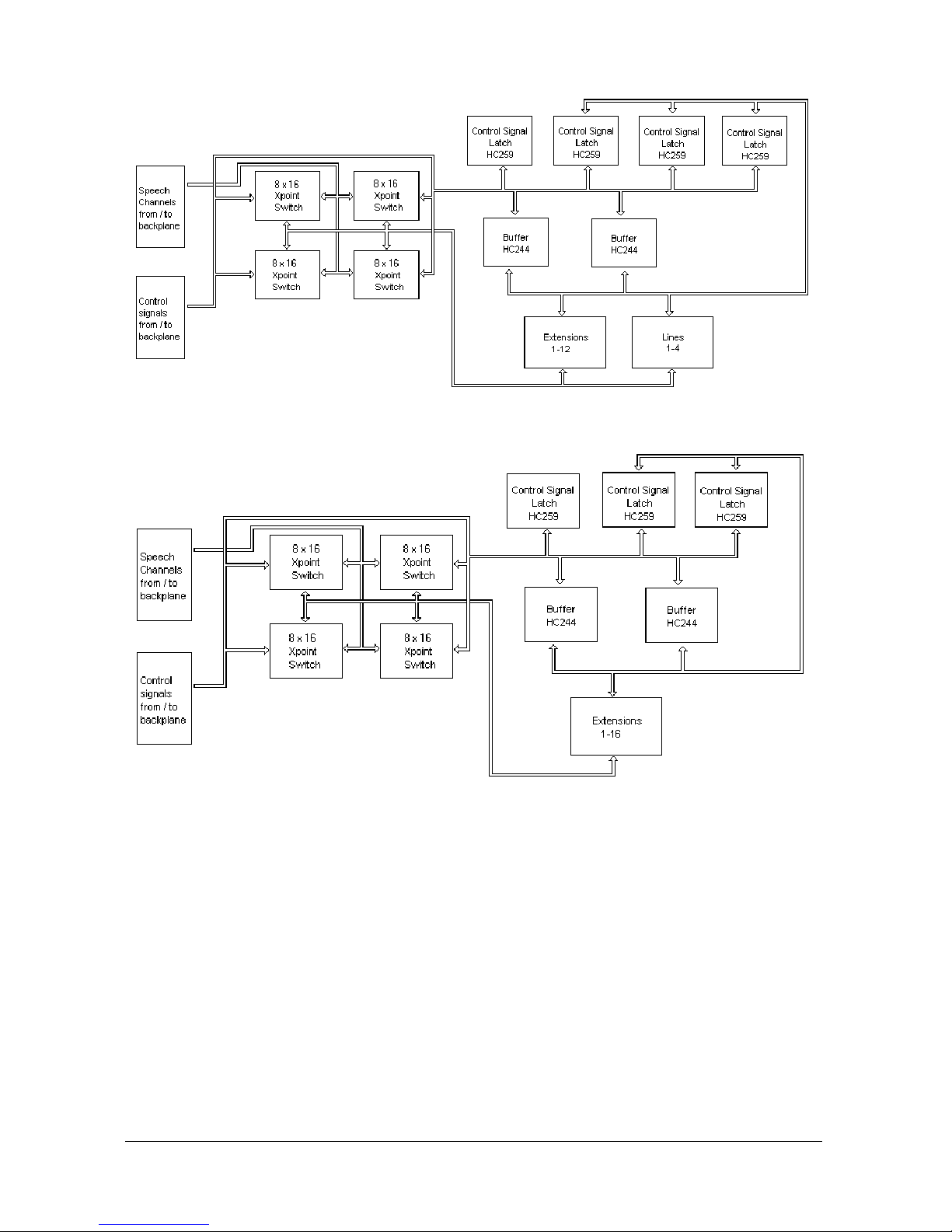
MS224 EX1 consists of MS224 EX1B and CON1 cards. Similarly, MS224 EX2
includes MS224 EX2B and CON2 cards. MS224 EX1B and MS224 EX2B are the
capacity expansion boards, having extension circuitries as well as bus receiving
circuitries. MS224 EX1B card employs line circuitries as well. See Figure A-8 for
the location of these circuitries as well as Figures A-10 and A-11 for the operational
flow diagrams of MS224 EX1 and EX2 Expansion Boards, respectively.
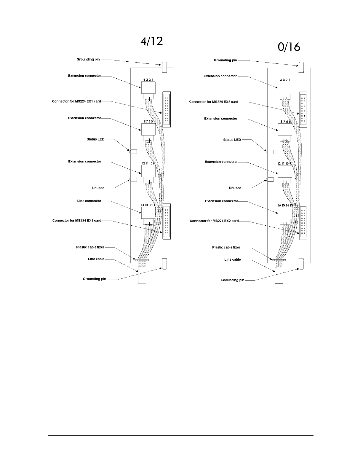
CON1 and CON2 Connection Cards are the interface boards between the
extension telephones / external lines and the MS224 EX1B and EX2B cards,
respectively. CON1 and CON2 have the extension / line connectors as well as
some protection and filter elements. The optional 16-pair MDF cables, named CBL16, are also available for the connection of extension telephones and external lines
to CON1 and CON2.
The cabling of extension telephones and external lines are established through the
8-pin RJ sockets on CON1 and CON2. Each RJ socket can be used to connect 4
extension telephones or lines. So, CON1 card has 3 RJ sockets (for 12 extension
telephones) and 1 RJ socket (for 4 external lines), whereas CON2 card has 4 RJ
sockets (for 16 extension telephones). See the following figure for the cabling of
extension telephones and external lines to CON1 and CON2, via CBL-16 cable or
any similar cable procured locally.
Karel MS224 Installation & Maintenance Guide
Edition 3.2
15
Figure A-9
CON1 lays on the component side of MS224 EX1B, in such a way that the two 20pin connectors on component side of CON1 are attached to the corresponding
connectors on the component side of MS224 EX1B. The same also applies to the
connection of CON2 and MS224 EX2B. The pin-outs of the CON1 – MS224 EX1B
and CON2 – MS224 EX2B connectors are illustrated in the following tables :
Karel MS224 Installation & Maintenance Guide
Edition 3.2
16
CON1 – MS224 EX1B Connector
K2 Signal K2 Signal K3 Signal K3 Signal
1 SUB1A 11 SUB1B 1 SUB9A 11 SUB9B
2 SUB2A 12 SUB2B 2 SUB10A 12 SUB10B
3 SUB3A 13 SUB3B 3 SUB11A 13 SUB11B
4 SUB4A 14 SUB4B 4 SUB12A 14 SUB12B
5 SUB5A 15 SUB5B 5 TRK5A 15 TRK5B
6 SUB6A 16 SUB6B 6 TRK6A 16 TRK6B
7 SUB7A 17 SUB7B 7 TRK7A 17 TRK7B
8 SUB8A 18 SUB8B 8 TRK8A 18 TRK8B
9 LED1 19 LED2 9 - 19 -
10 - 20 - 10 - 20 GND
CON2 – MS224 EX2B Connector
K2 Signal K2 Signal K3 Signal K3 Signal
1 SUB1A 11 SUB8A 1 SUB9A 11 SUB16A
2 SUB1B 12 SUB8B 2 SUB9B 12 SUB16B
3 SUB2A 13 SUB7A 3 SUB10A 13 SUB15A
4 SUB2B 14 SUB7B 4 SUB10B 14 SUB15B
5 SUB3A 15 SUB6A 5 SUB11A 15 SUB14A
6 SUB3B 16 SUB6B 6 SUB11B 16 SUB14B
7 SUB4A 17 SUB5A 7 SUB12A 17 SUB13A
8 SUB4B 18 SUB5B 8 SUB12B 18 SUB13B
9 LED1 19 LED2 9 - 19 -
10 - 20 - 10 - 20 GND
Karel MS224 Installation & Maintenance Guide
Edition 3.2
17
MS224 EX1B and MS224 EX2B cards are connected to the BPL224 Backplane
through the 96-pin connectors on BPL224. The pin-out of the MS224 EX1/EX2 –
BPL224 connector is illustrated in the following table :
MS224 EX1/EX2 – BPL224 Connector
Pin Signal Pin Signal Pin Signal Pin Signal
1 + 1 VDC 25 X31 49 X9 73 2 - 5 VDC 26 X21 50 X7 74 3 CONT3 27 X18 51 GNDCPU 75 4 - 28 X16 52 X13 76 5 CONT1 29 + 5VDC 53 X5 77 6 - 30 RING 54 X2 78 VAG
7 CONT2 31 GND 55 X27 79 8 B 32 -24 VDC 56 X24 80 +5 VPU
9 DA1 33 + 12 VDC 57 X22 81 10 DA2 34 -5 VDC 58 X28 82 11 A 35 A0 59 X19 83 GNDCPU
12 C 36 A1 60 X17 84 X15
13 SUB1A 37 A2 61 + 5VDC 85 X14
14 VAG 38 CS 62 RING 86 X3
15 X10 39 DATA 63 GND 87 X0
16 + 5 VCPU 40 RD 64 - 24VDC 88 X25
17 X8 41 WR 65 - 89 X29
18 X6 42 - 66 - 5VDC 90 X30
19 GNDCPU 43 DA0 67 SERISDN 91 X20
20 X12 44 D 68 - 92 21 X4 45 SUB1B 69 - 83 +5 VDC
22 X1 46 VAG 70 - 94 RING
23 X26 47 X11 71 - 95 GND
24 X23 48 + 5VCPU 72 - 96 -24 VDC
There is a LED on the front panel of CON1 / CON2 cards. This LED turns on when
any port on the card is in use. During Reset or Parameter Download these LEDs
remain on.
Karel MS224 Installation & Maintenance Guide
Edition 3.2
18
Figure A-10
Figure A-11
The dimensions of the MS224 EX1B are 24.5 cm x 25.5 cm and the weight is 0.3
kg.
The dimensions of the MS224 EX2B are 24.5 cm x 25.5 cm and the weight is 0.26
kg.
The dimensions of the CON1 / CON2 are 22.5 cm x 5 cm and the weight is 0.06 kg.

Karel MS224 Installation & Maintenance Guide
Edition 3.2
19
I.6. EXTERNAL MUSIC CONNECTOR
Any external music source (tape recorder, radio or CD player) can be connected to
the system to be used for background music facility and to be transmitted to the
parties parked or put on hold. This connection is established via the 2-pin MUS
connector on MS224 CPUKON card.
I.7. EXTERNAL RELAY
An external relay which is rated for 250 VAC - 24 VDC at a maximum current of 2 A
exists on the MS224 CPUKON card to be used to activate either a door opener, an
external ringer, an external music source or an external announcement system.
The connection to the external relay is established through the 2-pin XREL
connector on MS224 CPUKON card. The selection among these devices is made
by programming.

Karel MS224 Installation & Maintenance Guide
Edition 3.2
21
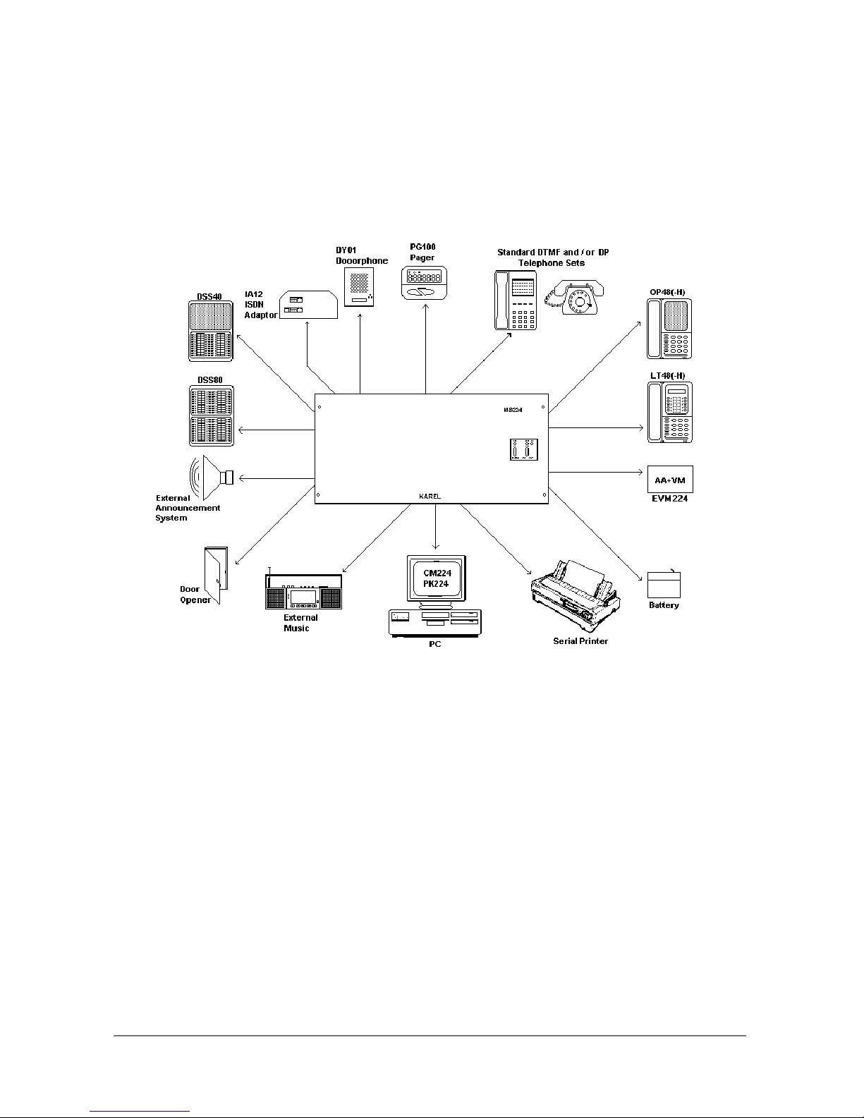
II. ACCESSORIES
To offer you a full telecommunication system, MS224 is equipped with many
accessories. These accessories are shown in the following figure and explained
one by one in the following sections.
Figure A-12
Karel MS224 Installation & Maintenance Guide
Edition 3.2
22
II.1. CONSOLES, FEATURE PHONES, DIRECT STATION
SELECT MODULES - OP 48(-H), LT48(-H), DSS8 0,
DSS40
OP48(-H) Consoles, LT48(-H) Feature Phones, DSS80 / DSS40 Direct Station
Select Modules are the members of the same telephone family, hence they have
similar cases.
The data cabling of these sets is made via the 6-pin RJ socket (named CONSOLE)
on the MS224 CPUKON card. The signaling between the system and consoles,
feature phones or DSS modules is illustrated in the following table :
MS224 CPUKON Card Telephone / DSS Card
CONSOLE Socket Pin No Signal RJ Plug Pin No
1 +12 VDC 6
2 Busy 3 A (ext.11) 3 (ext.11)
4 B (ext.11) 4 (ext.11)
5 GND 2
6 Data 1
The input of +12 VDC is regulated to +5 VDC by telephone / DSS cards.
II.1.A. OP48(-H) CONSOLE
There are two types of OP48 Consoles, OP48 Console and OP48-H Handsfree
Console, the second one being half-duplex. The OP48(-H) Console has a BDP
(Busy Display Panel) that shows the states of the first 40 extensions and the first
12 lines as well as some system features. There is also an 8-Character Display that
keeps the user informed about the calling/called extensions and dialed numbers as
well as some system features.
The outlook and BDP of OP48-H Console are illustrated in the following figures :
 Loading...