

Page 1

IP PBX
TECHNICAL REFERENCE
&
INSTALLATION GUIDE
05/06/2012
Page 2
TECHNICAL REFERENCE & INSTALLATION GUIDE
II
Page 3
TECHNICAL REFERENCE & INSTALLATION GUIDE
CAUTION
SINCE IPV50 SERIES IP TELEPHONE EXCHANGES ARE ELECTRONIC-BASED
PRODUCTS, THE REQUIREMENTS BELOW SHOULD BE FULFILLED IN
ORDER TO UTILIZE IT WITH DESIRED PERFORMANCE:
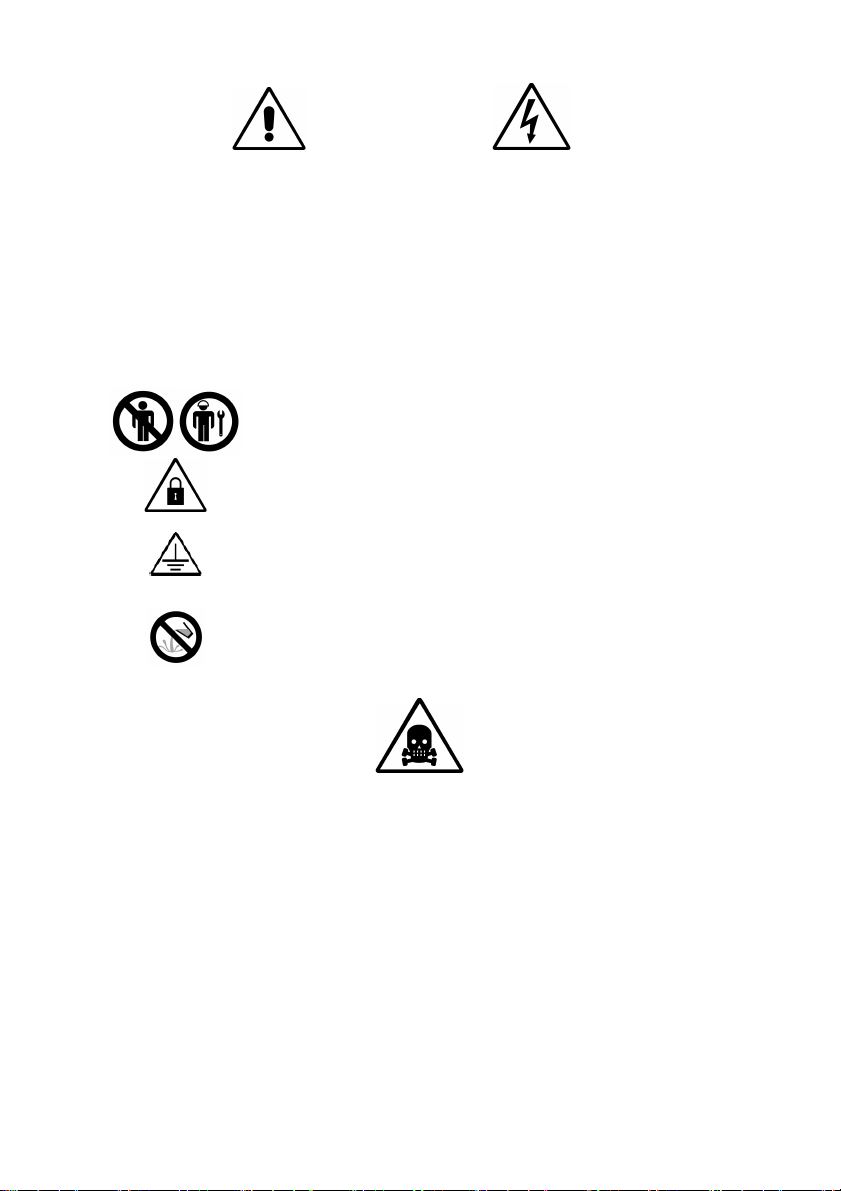
The system covers must not be opened by unauthorized
persons in any way.
The cover of the exchange cabinet should always be kept
closed.
All the ground connections on the covers must be fixed
and checked before closing all the covers of the system.
Precautions must be taken in order to prevent any harmful
substances from leaking or spilling into the exchange in
any way.
Serious hazards may occur unless the conditions above are matched completely!
III
Page 4

TECHNICAL REFERENCE & INSTALLATION GUIDE
CAVEAT
This device complies with part 15 of the FCC Rules. Operation is subject to the
following two conditions: (1) This device may not cause harmful interference, and
(2) this device must accept any interference received, including interference that
may cause undesired operation. Any Changes or modifications not expressly
approved by the party responsible for compliance could void the user’s authority to
operate the equipment.
Note: This equipment has been tested and found to comply with the limits for a
Class B digital device, pursuant to part 15 of the FCC Rules. These limits are
designed to provide reasonable protection against harmful interference in a
residential installation. This equipment generates uses and can radiate radio
frequency energy and, if not installed and used in accordance with the instructions,
may cause harmful interference to radio communications. However, there is no
guarantee that interference will not occur in a particular installation. If this
equipment does cause harmful interference to radio or television reception, which
can be determined by turning the equipment off and on, the user is encouraged to
try to correct the interference by one or more of the following measures:
--Reorient or relocate the receiving antenna.
--Increase the separation between the equipment and receiver.
--Connect the equipment into an outlet on a circuit different from that to which the
receiver is connected.
--Consult the dealer or an experienced radio/TV technician for help.
IV
Page 5

TECHNICAL REFERENCE & INSTALLATION GUIDE
CUSTOMER INFORMATION
1. This equipment complies with Part 68 of the FCC rules and the requirements
adopted by the ACTA. On the bottom of this equipment is a label that contains,
among other information, a product identifier in the format US: UL7IS00BIPV10. If
requested, this number must be provided to the telephone company.
2. A plug and jack used to connect this equipment to the premises wiring and
telephone network must comply with the applicable FCC Part 68 rules and
requirements adopted by the ACTA. A compliant telephone cord and modular plug
is provided with this product. It is designed to be connected to a compatible modular
jack that is also compliant. See installation instructions for details.
3. If this equipment [Karel IP PBX IPV10] causes harm to the telephone network,
the telephone company will notify you in advance that temporary discontinuance of
service may be required. But if advance notice isn't practical, the telephone
company will notify the customer as soon as possible. Also, you will be advised of
your right to file a complaint with the FCC if you believe it is necessary.
4. The telephone company may make changes in its facilities, equipment,
operations or procedures that could affect the operation of the equipment. If this
happens the telephone company will provide advance notice in order for you to
make necessary modifications to maintain uninterrupted service.
5. If trouble is experienced with this equipment [US: UL7IS00BIPV10], for repair or
warranty information, Service can be facilitated through our office at:
U.S. Agent Company name:
RONCO COMMUNICATIONS
Address: 84 Grand Island Blvd
Tonawanda, NY 14150
Tel: 716-873-0760
Fax: 716-879-8189
If the equipment is causing harm to the telephone network, the telephone company
may request that you disconnect the equipment until the problem is resolved.
Please check if KAREL has office or agent at USA to provide the repair or warranty
services? If not then, you can just provide the office at Turkey or other country.
6. Connection to party line service is subject to state tariffs. Contact the state public
utility commission, public service commission or corporation commission for
information.
7. If your home has specially wired alarm equipment connected to the telephone
line, ensure the installation of this [US: UL7IS00BIPV10] does not disable your
alarm equipment. If you have questions about what will disable alarm equipment,
consult your telephone company or a qualified installer.
8. If the telephone company requests information on what equipment is connected
to their lines, inform them of:
a) The ringer equivalence number [0.0B]
V
Page 6

TECHNICAL REFERENCE & INSTALLATION GUIDE
b) The USOC jack required [RJ11C]
c) Facility Interface Codes (“FIC”) [METALLIC]
d) Service Order Codes (“SOC”) [9.0y]
e) The FCC Registration Number [US: UL7IS00BIPV10]
9. The REN is used to determine the number of devices that may be connected to a
telephone line. Excessive RENs on a telephone line may result in the devices not
ringing in response to an incoming call. In most but not all areas, the sum of RENs
should not exceed five (5.0). To be certain of the number of devices that may be
connected to a line, as determined by the total RENs, contact the local telephone
company. The REN for this product is part of the product identifier that has the
format US: AAAEQ##TXXXX. The digits represented by ## are the REN without a
decimal point. For this product the FCC Registration number is [US:
UL7IS00BIPV10] indicates the REN would be 0.0B.
10. If this product is equipped with a corded or cordless handset, it is hearing aid
compatible.
VI
Page 7

TECHNICAL REFERENCE & INSTALLATION GUIDE
FOR PROPER OPERATION OF SYSTEM
Any mistake in the connections can damage your system. An authorized
service must make these connections. The information in this guide is given
just as explanatory information.
The equipment does not contain parts that can be repaired / maintained. In
case of a problem, consult authorized service.
To avoid danger of burning and electrical shock, do not expose the system to
rain or humidity.
Keep your system away from excessive dust, high temperature, humidity and
sunlight.
You can clean the exterior part of your system with a slightly humid fabric.
Before cleaning the system, remove it from mains power. Do not use any
chemicals, liquid or aerosol cleansers, flammable liquids (thinner, gasoline,
etc.) for cleaning purposes.
Do not mount your system on mobile surfaces or near radiators or heat
sources.
When you want to chance the location of the system, consult authorized
service. When you need to carry your system, use its own box.
Any external signal that will be used for testing your system or similar purposes
can damage your telephone equipment or your system.
Have your system installed in a ventilated place which is not exposed to direct
sunlight with a temperature of 5 - 40 Co and without any humidity. There should
be practical illumination within the room. The system must not be exposed to
dust, vibration, and any oil - water effect.
High frequency devices (welding machines, PC – telex and similar office tools,
air conditioners, televisions etc.) must be avoided as much as possible or must
be at least 3 meters away from the system.
Continuous power cut-offs will effect systems normal operation. Therefore, pay
attention to maintain proper power on your system.
VII
Page 8

TECHNICAL REFERENCE & INSTALLATION GUIDE
VERSION TABLE
Guide's Date / Version
21.1
2.2011
/AAA
05.06.2012/AAB
IPV10 Tech. Ref. and User Guide - Ver. AAB–05.06.2012
For the development and enhancement of the features of the products specified in
this document, KAREL reserves the right to make changes without prior notification.
Products might possess different features, depending on their software and
hardware versions.
VIII
Page 9

TECHNICAL REFERENCE & INSTALLATION GUIDE
TABLE OF CONTENTS
INTRODUCTION ................................................................................................. 1
GENERAL INFORMATION AND INSTRUCTIONS FOR USE ............................... 1
APPLICATIONS .................................................................................................. 4
IP PBX FEATURES ......................................................................................... 4
HARDWARE FEATURES ................................................................................ 4
PARTS LIST ON DELIVERY ....................................................................... 5
SYSTEM INSTALLATION ................................................................................... 6
CONNECTION DIAGRAM ........................................................................... 6
CONNECTING THE ETHERNET CABLE .................................................... 6
CONNECTION TO AN ELECTRIC SOCKET ............................................... 6
IPV10 EXCHANGE WALL INSTALLATION: ................................................. 7
MANAGEMENT OF THE IPV10 ......................................................................... 10
ADMINISTRATOR LOGIN ......................................................................... 10
SOFTWARE STRUCTURE ................................................................................ 11
THE IPV10'S OPERATING SYSTEM ........................................................ 11
IP EXTENSIONS AND LINE SERVICES ................................................... 13
LICENSING FEATURES ........................................................................... 15
NUMBERING PLAN .................................................................................. 15
WEB SERVER – COMSER ....................................................................... 16
SPECIFICATIONS ............................................................................................. 18
GENERAL SPECIFICATIONS ....................................................................... 18
CONNECTIONS ............................................................................................ 19
ANALOG CHARACTERISTICS...................................................................... 20
IP CHARACTERISTICS................................................................................. 21
TONE CADENCE & FREQUENCIES* ............................................................ 22
RING CADENCES* ....................................................................................... 23
DTMF TONES: .............................................................................................. 23
V
Page 10

TECHNICAL REFERENCE & INSTALLATION GUIDE
INTRODUCTION
IPV10 – An IP PBX for Small Offices and Home Offices
IPV10 — A hybrid IP-PBX for small offices, home offices and remote offices.
The IPV10 also offers a hybrid solution option (combining VOIP applications with
standard telecom equipment) for those companies not yet ready for a standalone
VoIP (IP Telephony) solution.
About the User Guide
By following the installation advice supplied here you can quickly and easily start
using your device.
Detailed explanations are provided in each related section of the user guide.
Please read the user guide carefully. In order to ensure problem-free operation of
the device, please pay special attention to the remarks concerning safety. The
manufacturer can not be held responsible for any result of not paying proper and full
attention to these points.
GENERAL INFORMATION AND
INSTRUCTIONS FOR USE
During Handling and Transportation, Please Pay Attention to the
Following
Do not expose your product to any impacts during handling. Remove the product
from its box carefully. Store all accessories in the box to prevent losing them.
Initially check the product for any potential damage incurred during transportation.
During Connection and Installation, Please Pay Attention to the
Following
The end user is responsible for all connections and installation being undertaken in
full accordance with the user guide. In the advent of any problem appearing during
connection or installation, please contact an authorized service shop. (Refer to the
list of authorized service shops)
Situations in which Periodic Maintenance is Required
So long as the instructions in the user's manual are complied with, the product will
not require any maintenance. The product should be serviced by authorized service
staff only if it runs abnormally, or if it does not run at all. After the expiry of the
warranty period, technical maintenance work must still be performed only by an
authorized service centre.
1
Page 11

TECHNICAL REFERENCE & INSTALLATION GUIDE
Details about the Maintenance, Repair and Cleaning of the Product
which can be Performed by the End User
The product does not contain any maintainable parts. If any failure does occur,
please contact one of the authorized service shops (Refer to the List of authorized
service shops) or the authorized reseller who initially sold the product.
Information regarding Energy Efficiency
Use the on/off button to turn the device off when the system is not in use.
Occurrences that may lead to Operational Failures
Failures arising due to the product being operated in violation of the instructions
provided in the user's manual.
Short-circuits when operated in hot or extremely humid environments.
Using any connection cables other than those provided by the manufacturer in the
product's box and accompanying the product .
Customizations, modification or the removal of components by either the user or by
any unauthorized service staff.
External physical impacts and direct breakage damages incurred by the product.
Destruction or removal of the product's batch number.
Any liquid being spilt on the product, or the product being exposure to water or to
extreme moisture.
Potential Dangers to the Health of Humans, or the Environment,
During Operation
Please comply with the following basic safety precautions before operating the
device.
All security warnings and user's instructions must be read carefully before operating
the product.
Please follow all warnings and notices indicated on the unit.
To prevent the product passing a stray electric current or other accident (e.g. due to
high temperatures) do not open the product's back cover. Contact the qualified staff
of an authorized technical service shop for any repair work that may be required.
Keep the product away from places that receive direct sunlight. Do not expose the
product to direct sunlight.
Install your device in a safe place. Make sure that the product's cables and cords
are not trampled on. Do not place on the cables any object that may cause wear or
damage to the cables.
2
Page 12

TECHNICAL REFERENCE & INSTALLATION GUIDE
Do not apply excessive force when pulling on any cable otherwise the cable may
become damaged.
Do not overload the sockets and patch cords otherwise you run the risk of electric
shock or fire.
Never allow unattended children to touch the device. Keep all packaging materials
away from children. The device's handset is magnetic. Pay attention to any small
metal objects (for example paper clips) which may become attached to the handset.
Due to negative impacts on both human and environmental health, do not dispose
of the product in domestic waste. Please dispose of it in a proper recycling box.
3
Page 13

TECHNICAL REFERENCE & INSTALLATION GUIDE
APPLICATIONS
IP PBX FEATURES
Auto-Configuration Call Transfer
IVR (Interactive Voice Response) Call Waiting
Blind Transfer CID
Call Record (CDR) Search Do Not Disturb (DND)
Call Forwarding Voice Message
Call parking Group Ringing
Call Pickup CID Routing
Call Recording 4-Person Conference Calling
Inbound/Outbound Call Routing MRI(IP-PBX Recording Interface)
DISA
HARDWARE FEATURES
EXTERNAL APPEARANCE
The Front Face
LED Definition
Power Green Led: Indicates that the power connection is normal
Run Green Led: Indicates that the server system is running normally
Ready Green Led: Indicates that the system is ready
Eth Green Led: Indicates that the internet interface is in use
Port1 Red: For the FXO port
Green:For the FXS port
Double blinking - Red, quickly:The FXO port cannot connect to the
PSTN line
Double blinking - Red and Green, quickly:The FXO port has detected
a call
Double blinking - Red and Green, very quickly:There is a call on the
FXO port
4
Page 14

TECHNICAL REFERENCE & INSTALLATION GUIDE
Double Blinking - Red and Green, quickly:The FXS port is ringing
LED Dual - Green and Red, quick:There is a Call on the FXS port
Back
PARTS LIST ON DELIVERY
One IPV10 server unit
One power source
One Internet cable
Some telephone cables [RJ-11]
Note: Please contact your reseller if any of the above-listed components are
damaged or missing.
5
Page 15

TECHNICAL REFERENCE & INSTALLATION GUIDE
SYSTEM INSTALLATION
ConnectIon Diagram
ConnectIng the Ethernet Cable
The IPV10 has one 10/100M Ethernet port with RJ45 interfaces and LEDs. In
addition to the transfer of voice data, the device also communicates data related to
Ethernet port management, maintenance and operation.
Connect the Ethernet cable to the IPV10's Ethernet port, and connect the other end
of the cable to a hub, switch, router, LAN or WAN. After connecting, check the LED
light: a yellow light indicates that the connection is in progress; a green light
indicates that the port is running.
ConnectIon to an ElectrIc Socket
Requirements of the IPV10 system:
AC Input: 100~240VAC – 50~60 Hz.
DC Output: 12V; 1 A
Please take the following steps when connecting the device to an electric socket.
1. Insert one end of the power cable into the input port on the back panel of IPV10.
Insert the other end into a 220V electric socket.
6
Page 16

TECHNICAL REFERENCE & INSTALLATION GUIDE
IPV10 EXCHANGE WALL INSTALLATION:
It is necessary to remove the front cover of IPV10 Exchange in order to hang it on
the wall. Remove the screws located underneath the box for this purpose. Move the
cover upwards using a screwdriver from its lower side as illustrated in picture so
that the grappling hooks located on top will release the cover.
7
Page 17

TECHNICAL REFERENCE & INSTALLATION GUIDE
Take the following steps to install the box with its front cover
removed to a wall:
1. Use IPV10 Exchange Installation Template to determine the location of the
terminal on the wall and to mark the location of the holes. The length of the
power adapter cable must be considered when determining installation
location.
8
Page 18

TECHNICAL REFERENCE & INSTALLATION GUIDE
Installation Template
2. Insert pegs inside the holes drilled on the wall and install the screws into
these pegs so that 4 mm from the head side of the screws will remain
unscrewed.
3. Figure below device hang on the wall by hitting hanger holes and screw
heads. If necessary, screws can be tighten.
4. Install the front cover. In order to secure the front cover, place the front
cover over the grappling hooks located at the top side of the box first and then
push the bottom side of the cover.
9
Page 19

TECHNICAL REFERENCE & INSTALLATION GUIDE
Note: There is no need to remove the electronic card from the box prior to installing
the box on the wall. However, should it be necessary to remove the card from the
box for any reason whatsoever, five screws illustrated in Figure-g must be removed
in order to remove the card.
MANAGEMENT OF THE IPV10
ADMINISTRATOR LOGIN
An IPV10 system has many software features. These services have been designed
in a flexible manner to order to satisfy all users' various expectations. All services
can be programmed via the IPV10's administration interface: ComSer. To do this,
double click on your PC's Internet browser icon to open a browser page, and then
enter the IP address of the IPV10 into the address bar.
For initial configuration of the IPV10, please use the IPV10's default login details to
log in
IP Address: http://192.168.180.8:8000
User Name: admin
Password: karel
10
Page 20

TECHNICAL REFERENCE & INSTALLATION GUIDE
SOFTWARE STRUCTURE
THE IPV10'S OPERATING SYSTEM
The operating system of the IPV10 IP PBX is Linux. The main software has been
designed based on UML, the most common object oriented software design
discipline. All the Linux-based software development was undertaken using the
Rapsody (I-logics) Suite.
Since Linux is an open-source operating system, applications such as Unified
Messaging and Call Center tools that have been developed for the same
environment can easily be adapted for use with a PBX.
The software has been designed to be CSTA-XML(ECMA) / CCXML (W3C)
compatible, in order to ensure full “computer-PBX” integration. Thus, any computer
applications compatible with these interfaces can be directly integrated with the
PBX.
Similarly, due to the Linux infrastructure, it is possible to integrate and use different
applications on the system.
11
Page 21

TECHNICAL REFERENCE & INSTALLATION GUIDE
The IPV10's main software is saved as a compressed Flash image in the memory
accompanying the CPU module. When the PBX initially starts running, it first loads
the operating system into RAM memory from the compressed Flash memory, runs
it, and then the system switches to its normal operating mode.
The system does not run any special software on its capacity expansion cards; all
operations are controlled by the main processor. This results in a simpler and more
reliable structure, perfect for a small or medium sized system.
System software updates do not require any changing of chips. There are two
options when considering updates to system software:
1) The version of the software may be changed along with replacing the CPU
module. However, this is a pretty expensive approach.
2) Alternatively, software can be uploaded remotely without interfering with the
system's normal operation by simply connecting to an IP network. This is
cheaper, much more reliable and faster as it does not require any stopping of
the system. So this method is recommended.
IMPORTANT
The system software can be updated while the PBX continues to run.
12
Page 22

TECHNICAL REFERENCE & INSTALLATION GUIDE
The IPV10's software has been designed to satisfy a broad range of customer
requirements. Looking at system software, there are three categories:
1. User features,
2. Operator features,
3. Programs.
User features are those which any user can access through any type of phone.
Operator features are those software abilities that can only be utilized by those
extensions authorized to do so by the system.
In general, programming of the system is undertaken via remote access, from a
computer's web browser to the W eb Server on the IPV10 (ComSer). Most of the
parameters that control the system's operation can be changed by programming.
In addition, some operator-level programs can also be accessed by those
extensions that have been provided with authorization to login into the programming
mode via dialing the appropriate code on the telephone.
Initially, access to the system's Web server is provided to those users defined as
'operators' or as 'system authorities'.
IP EXTENSIONS AND LINE SERVICES
One of the most important features of the IPV10 IP Telephone PBX is the provision
of integrated support for IP Extensions and IP Lines.
A maximum of 20 IP Extensions and 8 VoIP channels with associated IP Lines are
supported by an IPV10 PBX's integrated IP Extensions and Lines.
IP extensions run the SIP protocol. IP Lines support both the H323 and SIP
protocols. (Support for both the H323 and the SIP protocol are supplied by a single
MGW card)
The parametric programming of IP extensions and IP lines on the system is
undertaken via an interface to ComSer, similar to the programming of the other
TDM channels of the PBX.
The System's number of Gateway channels is a maximum of 8. Thanks to this,
there will not be any transition limitation on calls between IP and analog ports.
IP extensions registered to the PBX can use all standard SIP services, but they
cannot use all of the services available to the PBX's other analog/digital extensions.
They can only use specific PBX services. Some of the services that can be used by
IP extensions are listed here:
- Shared Memory Records / Searches in Shared Memory
- Call Parking
- Call Pick Up / Group Call Pick Up
13
Page 23

TECHNICAL REFERENCE & INSTALLATION GUIDE
- Call Forwarding
- Conference calls
- Completion of a Call to a Busy Subscriber
- Authorization Transfer
- CLIR Activation
- CLOR Activation
- Executive Secretary Feature
- Leaving a Message for a Selected Extension
For further information on all the services supported by IP Extensions, please refer
to the IPV10 Series User's Guide.
An IPV10 extension supports IP extensions via its IP services. Thus IP extensions
can be supported behind ADSL. To enable this the system supplies NAT/STUN
support.
During IP connections to a VPN, the IP extension applications act as if they were
connected locally. IP port routing is not required.
IP wireless phones (WiFi phones) and IP Dect System are both supported by IPV10
PBX IP services. Thus WiFi and IP Dect extensions can also obtain services from
the system, similar to that provided to standard SIP extensions.
WiFi phones are IP phones which connect via special IP switches named direct
wireless access points. Actually, as a result these are not in any way different from
IP phones connected to a normal switch on a local network.
IP Dect and WiFi phones must be directly registered on the SIP Server if the IPV10
PBX is to be able to service them.
IP Lines can be selected so as to support the H323 and SIP protocols. The system
can include lines supporting the SIP and H323 protocols at the same time.
IP Lines can be used to build IP connections (Tie-Lines) between PBX's. They can
also be used to connect to a private operator's IP lines or to Proxy
Servers/GateKeepers throughout the company.
After IP Lines have been defined via the ComSer interface, line groups are similarly
created for the other lines groups, the routes are defined and then put into service.
14
Page 24

TECHNICAL REFERENCE & INSTALLATION GUIDE
LICENSING FEATURES
The use of IP extensions and lines on an IPV10 IP Telephone PBX requires special
licenses. In addition, further features can be utilized via these special licenses. The
features that require licenses are listed in the following list:
1. Web-CM+Net-Console or Net-CM+Net-Console License
2. Private IP Extension License
3. SIP Extension License
4. SIP&H.323 Line License
5. VoIP Encrypted&Unencrypted Channel License
6. Instant Messaging License
7. EVM Channel License
On a IPV10 IP Telephone PBX, by default:
Eight (8) SIP PBX's + Two (2) Private IP Extensions + Two (2) SIP Lines + Four (4)
VoIP Channel License are supplied.
Licensing features are enabled via a security code embedded in the IPV10's
mainboard.
Please contact your authorized service shop for License Keys. License keys you
request and purchase can be entered into the License Settings field on the ComSer
interface.
NUMBERING PLAN
When the installation of a IPV10 IP Telephone PBX of the required capacity is
completed and the device is initially run, it automatically scans its configuration and
assigns a numbering structure which conforms to the configuration of the lines, as
listed.
The IPV10's numbering is done dynamically, but in accordance with its
configuration. Extensions with that already have values assigned to them are added
onto the existing numbering plan as new cards are added to the system. These
extensions' numbers are then assigned, starting from the highest number of the
existing plan.
Initially, the numbering plan is assigned in three steps, beginning at 101 and then
incrementing by one for each extension. That is, the existing plan's numbers are
extended, one by one, as each extension or line card is added to the system.
If required, the PBX's numbering plan and code structure can be modified as
desired, due to its flexible numbering. The desired numbering plan can be created
in a maximum of eight steps.
15
Page 25

TECHNICAL REFERENCE & INSTALLATION GUIDE
WEB SERVER – COMSER
The IPV10's maintenance, programming and monitoring actions can all be realized,
in real-time, from any remote computer on the same network as the IPV10.
To do this, a WEB server, ComSer, has been designed for the IPV10, thus
eliminating the need for any special software while, at the same time, allowing
access to the PBX from any web browser.
Thus each user can utilize the PBX's functionality from his or her computer, given
the appropriate authorization. Moreover, because the web server is an integrated
component of the IPV10's operating system, there will not be any incompatibility
between application versions.
Backups can be saved on a local computer via the ComSer web server. Previously,
saved backups had to be restored to the system via the "Database Converter".
However, older configurations can still be used with these newer versions.
All of the following operations can be undertaken via the integrated web server:
1) PBX programming
a) Programming all of the interface parameters
b) The setting of all extension and line parameters
c) The programming of general PBX parameters
d) The programming of all administration and routing parameters
2) System updates
a) Updating server settings
b) The display of the current software versions
c) Automatic software updates
d) Remote access to system settings, for export or recording
e) The changing of IP addresses
3) Call record details. (Net-CM or Web-CM will be used here):
a) Transfer of call record details to a local computer
b) Pricing
c) Filtering, archiving and the compiling of statistical data
16
Page 26

TECHNICAL REFERENCE & INSTALLATION GUIDE
The following window of the ComSer programming interface appears:
17
Page 27

TECHNICAL REFERENCE & INSTALLATION GUIDE
SPECIFICATIONS
GENERAL SPECIFICATIONS
1. Capacity
(TDM)
Capacity (IP)
2. Testing - Blackfin DSP
3. Switching - PCM/TDM A rule
4. Power - 110~240 VAC – 50~60 Hz.
5. Dialing - Dual Tone Multi Frequency Dialing (DTMF) 140 msec
6. Dialing
Conversions
- A single system with four (4) lines
- A maximum of . 20 IP lines
- IP
- Mainboard + CPU module Stand-by Power
Consumption: 1W
- EXP20 Stand-by Power Consumption: 0.5W
- Max. Power Consumption: 20W
(analog lines)
- Digital (info)
- IP (RFC283 info)
- DTMF – DP
- RFC283 – info elements
7. Speech
Channels
(TDM)
Speech
Channels (IP)
8. MF Receiver
Capacity
9. MF Producer
Capacity
10. CRL Capacity - Approximately 2000 Calls
- 4 x 4
- IP to IP in local network unlimited.
- IP to TDM 4 channels
- 4
- 4
18
Page 28

TECHNICAL REFERENCE & INSTALLATION GUIDE
CONNECTIONS
1. Connectors - Lines and Extensions: RJ11 type
- Ethernet: RJ45 type
2. External
Connections
3. CRL
(Call Record
Listing)
- Standard Telephones: 2-wire
- PC: 10baseT Straight Cable
- WEB-CM
- Net-CM
19
Page 29

TECHNICAL REFERENCE & INSTALLATION GUIDE
ANALOG CHARACTERISTICS
1. Analog Extension
Interface
2. Maximum Analog
Line Cycle
Resistance
- Station Loop Resistance: Maximum 2500 Ohm,
including telephone set
- 2.2 kOhm
3. Analog Line Interface
4. Analog Extension
Supply Voltage
5. Wait Time between
Two Consecutive
Dials by the Autodialer
6. Cross-Talk
Attenuation
7. Maximum number of
telephone sets per
extension
8. Auto attendant
message capacity
9. Total Voice Message
capacity
10. Ringer Voltage - 65 V rms, 25-30 Hz
11. Minimum Detectable
Ringer Level
- Analog line with Cycle Initiation through DTMF
Signaling
- 12/16 KHz Pulse Price Signal Detection
- Polarity Reversal Detection
- -48 VDC
- 175 _ 5 msn
- Better than 70 dB
- 2 Telephone Sets (for analog extensions)
- 10 minutes
- 14 hours
- 35 V rms, 25-30 Hz
12. Hook flash Duration - 100 – 600 msec*
13. Environmental
Conditions:
14. Dimensions - 220x144x62mm
15. Weight - 500 g
16. Maintenance - Embedded Self Test / Solution
- 0C0 – 40C0 , Humidity 10%–80% non-condensing
- Local / Remote Programming
20
Page 30

TECHNICAL REFERENCE & INSTALLATION GUIDE
IP CHARACTERISTICS
1. Voice compression
(Codec support)
2. Echo removal - period - 16 msec EC (conforms to the G.168 standards)
3. In-band support - Yes
4. Out-of-band - RF2833 support
5. Telephone - Standard SIP softphone
6. Web server support - Yes
7. System
Management/Monitori
ng
8. SNTP - Yes
9. NAT support - Yes
10. QoS support - Yes
11. Jitter buffer - Yes
12. sRTP support - Yes
- G711 a/u-law
- G729A/B
- G723.1
- iLBC
- INFO support
- IP phones
- SIP-compatible WiFi wireless phones (support
802.11g protocol)
- HTTP, Telnet, TFTP
13. CNG support - Yes
14. VAD support - Yes
15. DNS support - Yes
16. STUN support - Yes
21
Page 31

TECHNICAL REFERENCE & INSTALLATION GUIDE
TONE CADENCE & FREQUENCIES*
1. Dial Tone (500 Hz.) Continuous
2. Ring back Tone (500
Hz.)
3. Busy Tone (500 Hz.) 500 msec on, 500 msec off
4. DISA Dial Tone (500
Hz.)
5. Dial Tone with
Message Waiting
(500 Hz.)
6. Error Tone (500 Hz.) 300 msec on, 300 msec off, 300 msec on, 300 msec
7. Dial Tone (Reminder
Active)
8. Special Dial Tone
(250 Hz.)
9. Overflow Tone (2000
Hz.)
10. Warning Tone (250
Hz)
1500 msec on, 3500 msec off
300 msec on, 300 msec off, 300 msec on, 300 msec
off, 300 msec on, 2000 msec off
300 msec on, 300 msec off, 300 msec on, 300 msec
off, 300 msec on, 2000 msec off
off, 300 msec on, 300 msec off, 700 msec on, 300
msec off
1000 msec 500 Hz., 1000 msec 250 Hz.
Continuous
700 msec on, 200 msec off
20 msec on, 1500 msec off
* Some tone and cadence values can be modified via the ComSer
programming interface.
22
Page 32

TECHNICAL REFERENCE & INSTALLATION GUIDE
RING CADENCES*
1. External Call, Call Back,
Reminder/Wake Up Calls
2. Internal Call 400 msec on, 350 msec off, 400 msec on,
*These values can be changed via the programming interface.
1500 msec on, 3500 msec off
3500 msec off
DTMF TONES:
High Frequency Group (- 7 dBm)
1209 Hz 1336 Hz 1477 Hz
Low 697 Hz 1 2 3
Frequency 770 Hz 4 5 6
Assembly 852 Hz 7 8 9
( - 9 dBm) 941 Hz * 0 #
The Nominal Frequencies of the IPV10 may deviate, by +/- 2.5 %, from the values
listed above.
23
 Loading...