

Page 1
12
IA
12
IA
ISDN ADAPTOR
08/2003
TECHNICAL REFERENCE AND USER'S GUIDE
Page 2
TECHNICAL REFERENCE AND USER’S GUIDE REV AAA
IA12 ISDN ADAPTOR
CAUTION
Since IA12 ISDN Adaptor is an electronic-based product, the requirements below should
be fulfilled, in order to utilize it with desired performance:
The adaptor must not be disassembled by unauthorized
persons in any way.
The cover of the adaptor cabinet should always be kept
closed.
Prior to hanging the adaptor on the wall, one should make
sure screws are not defective.
Precautions must be taken in order to prevent any harmful
substances from leaking or spilling into the adaptor in any way.
Failure in fulfilling these requirements may result in vital hazards!
IA12 USERS GUIDE - REVAAA 15/08/2003
KAREL reserves the right to make modifications in product features mentioned in this
document for development and improvement purposes, without prior notice. Individual
products may possess characteristics different from those mentioned in this document,
according to their software and hardware versions.
I
Page 3

TECHNICAL REFERENCE AND USER’S GUIDE REV AAA
IA12 ISDN ADAPTOR
II
III
PREFACE
Chapters in this guide have been prepared in order to present detailed technical
information to people who need hardware-based information about the IA12 ISDN
adaptor and instructing them for installation of the adaptor. By this way, one could
understand abilities of the IA12 ISDN adaptor, how it will be operated in accordance
with customer demands and things that should be done in order to operate it with full
performance.
First chapter - “Technical Introduction” - It contains technical information about
hardware and software structures of the adaptor. Information in this chapter, for
which knowledge in mechanics, electricity and electronics may be prerequisite, aims
to introduce structure of the adaptor. Presentation of the information in this chapter
follows a path from the whole of the adaptor down to the details of parts.
Second chapter - “Installation” - This chapter tells about the installation methods
according to the capacity of the adaptor. This chapter definitely must be read before the
installation by the personnel who will perform the installation of the adaptor.
Third chapter - “Programming” - This chapter gives short information about the software
characteristics, which would enrich functions of the adaptor and which could be applied
to meet daily communication needs of customers more comprehensively.
Last chapter-”Usage” - This chapter explains the things to be done in order to put the
device in use.
Best regards,
Karel
CONTENTS
TECHNICAL INTRODUCTION:.............................................................................................1
TECHNICAL SPECIFICATIONS:..................................................................................1
PARTS LIST ON DELIVERY:.......................................................................................4
COMPATIBILITY:..................................................................................................4
INSTALLATION:...............................................................................................................5
APPLICATION:.................................................................................................5
IA12 MOTHERBOARD AND EXP-IA12 EXPANSION CARD:.......................................5
CABLING:...... ......................... ....................... .. ....................... .................6
Data Line:................................................................................................................6
ISDN Line:................................................................................................................6
Analog Lines:..........................................................................................................6
IA12 ORDER DEFINITION:...........................................................................................8
PROGRAMMING:...............................................................................................................9
Line Status:.............................................................................................................9
DDI Root Number / MSN Number Definition:.....................................................9
MSN Number Comparison:.................................................................................10
Ringing Extension:................................................................................................10
IA12 General Parameters:.....................................................................................12
Channel-Specific Parameters:.............................................................................12
USAGE:...............................................................................................................14
Page 4
TECHNICAL REFERENCE AND USER’S GUIDE REV AAA
IA12 ISDN ADAPTOR
TECHNICAL INTRODUCTION
IA12 ISDN is a EURO-ISDN BRI compatible adaptor that serves as a converter between
analog lines of the MS-series exchanges (MS48S, MS128, MS224) and ISDN BRI lines
coming from local CO (NT1).
TECHNICAL SPECIFICATIONS
An IA12 ISDN Adaptor with basic capacity can serve an ISDN BRI line. That capacity could
be increased by addition of the EXP-IA12 expansion card, which supports one ISDN BRI
line, to IA12.
Since each ISDN BRI presents two speech channels, IA12 with EXP-IA12 can convert 4
analog lines of the MS systems to 2 ISDN BRI lines, whereas IA12 without EXP-IA12 can
convert only 2 analog lines to 1 ISDN BRI line.
The IA12 ISDN Adaptor communicates with the MS systems over the serial data line (KTS
line). At most 3 IA12’s can be connected to an MS system. However, in that case it is
possible to install an EXP-IA12 in the third adaptor.
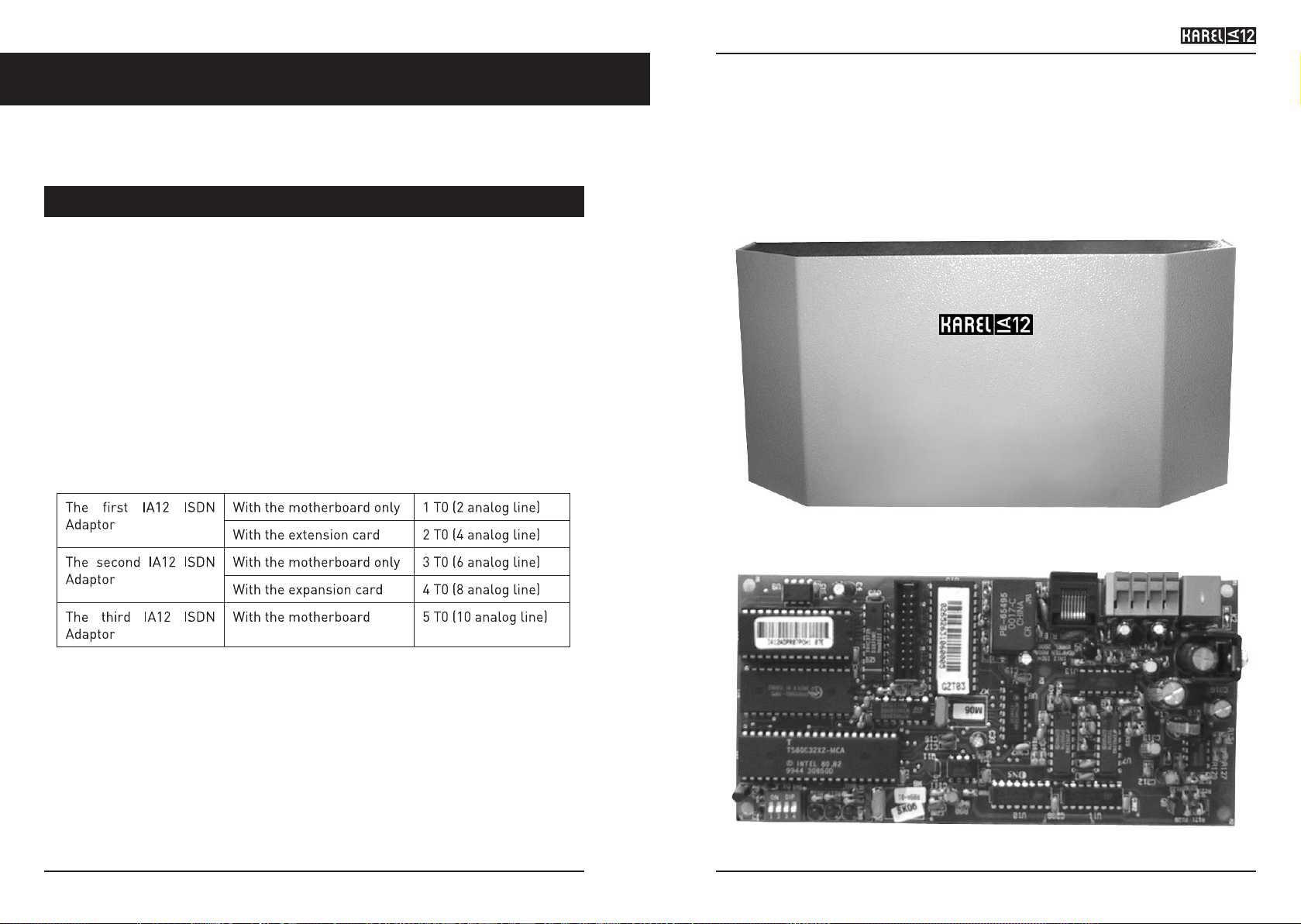
Current ISDN line capacities of the MS systems have been explained in the example
below:
The IA12 motherboard is connected by an 8-pin, RJ45 socket to the S0 that comes
from the NT1, to the A/B terminals of analog lines of the MS systems by two clip-type
connectors and to the serial data line by a 6-pin, RJ-type jack. At one end of the data
cable, which comes with the IA12, there is the connection box and at the other end there
is an RJ jack.
The EXP-IA12 expansion card is connected by an 8-pin, RJ45 socket to the S0 that
comes from the NT1, to the A/B terminals of analog lines of the system by two clip-type
connectors. The EXP-IA12 expansion card comes with a flat cable for connection to IA12,
which fits the 20-pin connectors of the IA12 motherboard and the EXP-IA12 card.
1
Moreover, there are three LEDs on the IA12 motherboard in order to monitor status of
the S0 line, as well as the data line. The LED at the right is turned on while the adaptor
and the ISDN line that is connected to the IA12 motherboard is operating simultaneously,
the LED in the middle is turned on while the adaptor and the ISDN line that is connected
to the EXP-IA12 card is operating simultaneously and the LED at the left is turned on
while the adaptor and the data line is operating simultaneously.
Appearances of theIA12 Motherboard and the EXP-IA12 card have been illustrated below;
Figure -1
2
Figure -2
Page 5

TECHNICAL REFERENCE AND USER’S GUIDE REV AAA
IA12 ISDN ADAPTOR
The following are present in the product package:
- IA12 ISDN Adaptor,
- IA12 ISDN Adaptor Technical Reference and User’s Guide,
- IA12 Data Cable,
- IA12 Installation Template.
IA12 ISDN Adaptor is compatible with the entire software of the MS48S exchange, 3.06
and later versions of the software of the MS48 and MS128 exchanges and the MS224
3.08O and later software.
ISDN lines in Point-to-Point (supports connection of one device only) or in Point-toMultipoint (supports connection of 8 different devices) structures can be connected to
the IA12 adaptor. In addition to that, as for the numbering plan, the numbering plans DDI
(Direct Dialing In) and MSN (Multiple Subscriber Numbering) are also supported by IA12.
Related settings can be done by the system software.
Besides, software structure of the IA12 ISDN Adaptor supports some ISDN features
specified below, which are EURO-ISDN compatible:
• Calling Line Identification Presentation (CLIP)
• Calling Line Identification Restriction (CLIR)
• Connected Line Identification Presentation (COLP)
• Connected Line Identification Restriction (COLR)
• Advice of Charge - At call Setup (AOC_S)
• Advice of Charge -During a call (AOC_D)
• Advice of Charge - At the End of the call (AOC_E)
In addition to that, the IA12 ISDN Adaptor can choose one of the carrier capacities
“Speech” or “3 KHz Audio” for outgoing calls.
Through OP48 (-H), LT48 (-H) or FT10 telephones, several ISDN network messages ad
call information can be viewed. Relevant ones, out of these messages, are also recorded
to the call record listings.
Dimensions of IA12 are 10 cm. x 21 cm. x 7 cm. and it weighs 0.9 kg.
Dimensions of EXP-IA12 are 9 cm. x 8 cm.
3
4
PARTS LIST ON DELIVERY
COMPATIBILITY
Page 6

TECHNICAL REFERENCE AND USER’S GUIDE REV AAA
IA12 ISDN ADAPTOR
5
6
CABLING
Data Line:
The IA12 Data cable comes with the IA12 ISDN adaptor. Like the telephone data cable of
the feature telephone sets and/or consoles, the data cable of IA12 also consists of two
parts. One of them is a cable with 6-pin RJ jacks at both ends and the other is the connection box. There is a 6-pin RJ socket at one end of the connection box; one end of the cable
is attached to the connection box. The other end of the cable is attached to the RJ socket
at the right side of the IA12 motherboard.
Signals on the connection box of the ISDN data cable are the same as the ones on the connection box of telephone data cable.
In order to make connection with IA12 ISDN Adaptor:
1- Data / +12 VDC / Ground signals on the connection box of the system data cable are
connected in parallel to the appropriate pins of the connection box of the IA12 data cable.
2- The RJ jack at the free end of the IA12 data cable is plugged into the RJ socket on
the IA12 motherboard.
ISDN Line:
One end of a cable, whose pin order is one-to-one, and which has 8-pin, RJ45 jacks at
both ends is attached to the RJ45 socket on the NT1 device and the other end to the RJ45
socket on the IA12 motherboard or the EXP-IA12 card.
Analog Lines:
Each ISDN BRI line is converted to two analog lines.
A pair of consecutive lines (such as lines 01, 02 or 03, 04), of an MS exchange is
connected to the clip-type connectors on the IA12 motherboard or the EXP-IA12 card. It
is very important to pay attention to the order of lines, while making those connections.
IMPORTANT
THE FIRST CHANNEL OF THE IA12 MOTHERBOARD OR EXP-IA12 CARD MUST
BE CONNECTED TO LINES WITH ODD NUMBERS (EX: 01, 03, 05…19) AND THE
SECOND CHANNEL TO EVEN NUMBERED LINES.
INSTALLATION
APPLICATION
The IA12 Adaptor has been designed to be mounted on the wall. In order to do that:
1- Two holes are drilled into the wall with a distance of 17.5 cm in between.
2- The anchor plugs are tightly driven to the holes.
3- Screws are inserted into the anchor plugs and then fixed.
4- The adaptor is hanged by coinciding the holes at the back to those screws.
IA12 MOTHERBOARD AND EXP-IA12 EXPANSION CARD
IA12 motherboard comes in the cabinet. That card has been fixed with lead card
holders.
EXP-IA12 Expansion card, too, has been fixed with brass card holders to the motherboard.
Communication between the IA12 motherboard and EXP-IA12 card is maintained with a
20-pin flat cable. The figure below shows that connection.
Figure -3
Page 7

TECHNICAL REFERENCE AND USER’S GUIDE REV AAA
IA12 ISDN ADAPTOR
The cable connections mentioned above is illustrated in the figure below:
(The first channel of the EXP-IA12 or the IA12 card must be connected to the line 01 or 03.
Afterwards, if the first channel has been connected to line 01, then the second channel
must be connected to line 02 or if the first channel has been connected to line 03, then
the second channel must be connected to line 04.)
7
Figure-4
8
IA12 ORDER DEFINITION
There are 4 micro-switches on the IA12 motherboard. These micro-switches are used
for defining the order of the IA12 ISDN adaptors that have been connected to the system.
For the first adaptor, the entire micro-switches must be OFF. For the second adaptor,
the micro-switch “3” must be ON and the others must be OFF. For the third adaptor, the
micro-switch “2” must be ON and the others must be OFF. These settings are shown in
the figure below:
When the installation is over and IA12 is put in service, together with the system it has
been connected to, whether IA12 has established proper connection with the system and
the ISDN lines can be figured out through three LEDs that are on the IA12 motherboard.
The LED at the right is turned on if a connection has been established with the ISDN line
that is attached to IA12 motherboard.
The LED in the middle is turned on if a connection has been established with the ISDN
line that is attached to EXP-IA12 expansion card. If IA12 has established connection with
the data line of the exchange, then the LED at the left is turned on. However, in order for
these LEDs to be put on line, first of all the lines attached to IA12 are supposed to be put
in service by programming.
In case any of the LEDs is still off after 1 minute, even though programming has been
done, you should report the situation to your authorized reseller.
Page 8

TECHNICAL REFERENCE AND USER’S GUIDE REV AAA
IA12 ISDN ADAPTOR
The programming is performed by the system supervisor (extension with number 11(11)
by default) in the exchange to which IA12 is attached.
In order for any program to be entered, first the exchange must be put into programming
mode by the system supervisor extension.
The most important point to be careful is the structural characteristics of the ISDN line
obtained from CO. Programming those features correctly is important for utilizing that
ISDN line, which is attached to IA12, effectively.
Line Status:
Parameters:
D : Line number
P : 1 The first IA12 ISDN adaptor that is attached to the system
: 2 The second IA12 ISDN adaptor that is attached to the system
: 3 The third IA12 ISDN adaptor that is attached to the system
T : 1 Lines D and D+1 of the system that is attached to the motherboard of
the IA12, which has been determined by the parameter P, are put into
service.
: 2 Lines D and D+1 of the system that is attached to the EXP-IA12
expansion card of the IA12, which has been determined by the
parameter P, are put into service.
Default:
P = 0, T= 0 for all lines.
Notes:
• Line number D should be odd (such as 01, 03, 17...)
• If an odd-numbered line is put into service, then so is the consecutive even numbered line.
• If parameter P becomes 3, then the parameter T should not be entered as 2.
DDI Root Number / MSN Number Definition:
Parameters:
P : 1 The first IA12 ISDN adaptor that is attached to the system
: 2 The second IA12 ISDN adaptor that is attached to the system
: 3 The third IA12 ISDN adaptor that is attached to the system
R : 1 ISDN line on the IA12 motherboard
: 2 ISDN line on the EXP-IA12 expansion card
S : 1, ……, 8 Index for the presented MSN number
T : Telephone number (at most 10 digits)
PROGRAMMING
9
89 D 12 P T
80042 P 01 R S T
10
Default:
No MSN number has been defined.
Notes:
• When that program is entered, MSN Number Comparison program is automatically
activated.
• The telephone number defined by T should be of at most 10 digits.
MSN Number Comparison:
It provides for comparison of the number that has been defined through the DDI Root
Number/MSN Number Definition program and the numbers coming from the local C.O.
Parameters:
P : 1 The first IA12 ISDN adaptor that is attached to the system
: 2 The second IA12 ISDN adaptor that is attached to the system
: 3 The third IA12 ISDN adaptor that is attached to the system
R : 1 ISDN line on the IA12 motherboard
: 2 ISDN line on the EXP-IA12 expansion card
S : 1, ……, 8 Index for the presented MSN number
T : 1 The system makes comparison
: 0 The system does not make comparison
Default:
T=1.
Ringing Extension:
It provides for defining separate ringing extensions for the ISDN numbers obtained from
CO. The programming may differ according to the Cases mentioned below:
a. Case 1: If the line is in MSN configuration, or it is in single-digit DDI configuration,
b. Case 2: If the DDI numbers are two-digit and Flexible Numbering is active in the system,
c. Case 3: If the DDI numbers are two-digit and Flexible Numbering is not active in the system,
CASE 1:
8005 D P A
Parameters:
D : Line number
P : 1,……, 8 Index for the MSN number
: 0, ……, 9 Last digit of the DDI number obtained from CO
A : Ringing extension
80042 P 02 R S T
Page 9

TECHNICAL REFERENCE AND USER’S GUIDE REV AAA
IA12 ISDN ADAPTOR
11
Notes :
• D should be an odd-numbered line. (Example:01, 03,…). This program, which is
entered for the line with number D, is considered to be entered for D+1 as well.
CASE 2:
80054 D P
Parameters:
D : Line number
P : Prefix that is appended to the beginning of the DDI number obtained from CO,
which the system employs to determine the ringing extension (Example: If
P=10 and the DDI number obtained from CO is 20 then the ringing extension is
1020.)
Notes :
• D should be an odd line number (such as 01, 03...) This program, which is entered
for the line with number D, is considered to be entered for D+1 as well.
• P could be of one or two digits.
• Since the last two digits of the DDI number and the parameter “P” will determine
the ringing extension the desired numbering plan should be created through the
flexible numbering.
CASE 3:
80054 D P T
Parameters:
D : Line access code
P : Prefix, which the system will use to determine the ringing extension
T : 1 The system does subtraction operation in order to determine the
ringing extension
: 0 The system does addition operation in order to determine the ringing
extension
Notes:
• D should be an odd line number (such as 01, 03...) This program, which is entered
for the line with number D, is considered to be entered for D+1 as well.
• P could be of one or two digits.
• The parameter T:
- If T=1 is coded, then the parameter P is subtracted from the DDI number
obtained from CO, the result is added to 100, thus the system determines the
ringing extension.
Example: If P=08 and the DDI number obtained from CO is 30, then the ringing
extension is ((30-08)+100)= 122.
- If T=0 coded, then, the parameter P is added to the DDI number obtained
from CO, the result is added to 100, thus the system determines the ringing
extension.
Example: If P=09 and the DDI number obtained from CO is 30, then the ringing
extension is ((30+09)+100)= 139.
12
IA12 General Parameters:
Several parameters are defined that could be used together with both channels of IA12.
Parameters:
P : 1 The first IA12 ISDN adaptor that is attached to the system
: 2 The second IA12 ISDN adaptor that is attached to the system
: 3 The third IA12 ISDN adaptor that is attached to the system
Q : 11 Display indicator
: 13 Number of digits for DDI
: 99 Reset
R : 1 Feature determined by the parameter Q is active
: 0 Feature determined by the parameter Q is not active
Notes:
• Display Indicator: If it is active, then information about status of the call and network
information are transmitted to the system by IA12.
Display Indicator is not active by default.
• Number of DDI digits: Number of digits in a DDI number, which is supposed to
come according to the numbering plan obtained from CO, is determined. After these
parameters, the parameter R takes on a value in the range 1-7, so as to determine
number of digits in DDI number.
• Reset: When this program is entered, the programs “MSN Number definitions”,
“MSN number comparison”, “IA12 general parameters” and “Channel-specific
parameters” (These programs are stored in the non-volatile memory of IA12)
take on their default values. The parameter R should not be entered for this
feature.
Channel-Specific Parameters:
Parameters:
P : 1 The first IA12 ISDN adaptor that is attached to the system
: 2 The second IA12 ISDN adaptor that is attached to the system
: 3 The third IA12 ISDN adaptor that is attached to the system
Q : 02 Filter bit
: 03 DDI selection
: 09 Automatic line configuration
: 10 Point-to Point connection
R : 1 ISDN line on the IA12 motherboard
: 2 ISDN line on the EXP-IA12 expansion card
S : 1 Feature determined by the parameter Q is active
: 0 Feature determined by the parameter Q is not active
80040 P Q R
80041 P Q R S
Page 10

TECHNICAL REFERENCE AND USER’S GUIDE REV AAA
IA12 ISDN ADAPTOR
13
Notes:
• Filter bit: If it is active, no comparison takes place between the ISDN line numbers
and the incoming calls, otherwise they are compared: It is required that the filter bit
is active for the DDI ISDN lines.
The “Filter Bit” is active by default.
• DDI selection: If it is active, then the ISDN line is defined as DDI, else as MSN.
DDI is active by default.
• Automatic line configuration: If it is active, then the information of whether the
ISDN line is Point-to-Point or Point-to-Multipoint is figured out through automatic
tests performed on the line. Otherwise, the configuration is supposed to be set
through programming.
It is active by default.
• Point-to-Point connection: If it is active, then that indicates that the structure of
the ISDN line is so as only one device can be connected to it. Otherwise, the line has
Point-to-Multipoint structure and more than one device can be connected to it.
By default it is not active for the IA12 motherboard, but active for the expansion card.
14
USAGE
IA12 ISDN Adaptor starts functioning automatically after the installation and programming
is finished and the PABX is powered on. This can be easily checked via the LEDs on the
motherboard.
The relevant information (like CLIP, AOC, etc.) about the ISDN calls are sent to the PABX
from IA12 through the serial data line. The information is sent to the display of the Karel
Feature Phones or Karel Consoles and preserved in the system memory to be used in
the Call Recods.
Page 11

TECHNICAL REFERENCE AND USER’S GUIDE REV AAA
IA12 ISDN ADAPTOR
15
16
Page 12

TECHNICAL REFERENCE AND USER’S GUIDE REV AAA
IA12 ISDN ADAPTOR
17
18
 Loading...