

Page 1

01/2003
G
T
20
GT
20
GT
10
TECHNICAL REFERENCE AND USER'S GUIDE
GSM GATEWAY
Page 2
TECHNICAL REFERENCE AND USER’S GUIDE REV A
GSM GATEWAY
Page 3
TECHNICAL REFERENCE AND USER’S GUIDE REV A
GSM GATEWAY
Dear KAREL Installer,
CAUTION!
Since GT20 and GT10 GSM Gateways are electronic-based systems they contain modules
that carry high voltages, which could adversely affect environmental conditions. In this
regard, the requirements below should be fulfilled in order for your gateway not to
create any situation against you or the environment:
The device must not be disassembled by unauthorized
persons in any way.
The cover of the gateway cabinet should always be kept
closed.
Prior to hanging the gateway on the wall, one should
make sure screws are not defective.
In order to maintain sound operation of the system, make sure the requirements
below, which are related to the environment in which the gateway will be installed, are
fulfilled.
♦ Make sure the upper screw by which the exchange will be hanged is at least 150 cm.
above the floor.
♦ Have your exchange installed in places, which are not exposed to direct sunlight,
and not humid, with an environmental temperature of 0-40oC and which should be
ventilated well. There should be a practical lighting in the room. The gateway should not
be exposed to effects of dust, vibration, oil and water.
♦ Devices that generate high frequency waves (such as welding machines, office
equipment such as computers and telex machines, air conditioners, TV sets) should not
be in the same room if possible, and they should be at least 3 meters away from the
gateway, otherwise.
♦ This module should be installed in a location inside the building but close to outer
walls, where GSM telephone network broadcast is received powerfully. In case lines
of different GSM operators are employed, signal levels for both of them should be
checked.
♦ Since frequently interrupted mains supply would affect normal operation of the
system, take care in making the power connection of the system special for the system.
Precautions must be taken in order to prevent any harmful
substances from leaking or spilling into the gateway or its
power adaptor in any way.
Failure in fulfilling those requirements may result in vital hazards!
GT20-10 TTMK/ÝNG - REV A 30/01/2003
KAREL reserves the right to make modifications in product features mentioned in this
document for development and improvement purposes, without prior notice. Individual
products may possess characteristics different from those mentioned in this document,
according to their software and hardware versions.
I
II
Page 4

TECHNICAL REFERENCE AND USER’S GUIDE REV A
GSM GATEWAY
PREFACE
Chapters in this guide have been prepared in order to present detailed technical
information to people who need hardware-based information about the GT20 and GT10
GSM Gateways, information about installation of the gateway, settings that could be done
through programming and troubleshooting simple problems. By this way, one could
understand abilities of the gateway, how it will be operated in accordance with customer
demands and things that should be done in order to operate it with full performance.
The first two sections - “Technical Introduction and Technical specifications” - They
contain technical information about hardware and software structures of the device.
Information in these chapters, for which knowledge in mechanics, electricity and
electronics may be prerequisite, aims to introduce structure of the gateway. Presentation
of the information in this chapter follows a path from the whole of the gateway down to
the details of parts. At the end, technical data have been listed in a table as summary.
The third section - “Installation” - This chapter tells about the installation methods of the
gateway. This chapter definitely must be read before the installation by the personnel
who will perform the installation of the gateway.
The fourth section - “Programming” - This chapter gives information about the program
parameters, which would enrich functions of the gateway and which could be applied to
meet daily communication needs of customers more comprehensively.
Last section - “Troubleshooting” This is a chapter that suggests simple solution methods
to some problems that could occur in orderly operation of the gateway. Solution
suggestions that are specified in this chapter can be applied by the authorized personnel
only.
TECHNICAL INTRODUCTION:.............................................................................................1
CONTENTS
INTRODUCTION:................................................................................................................1
GENERAL MODULE FEATURES:.......................................................................................2
PART LIST ON DELIVERY:...............................................................................................2
POWER SUPPLY:................................................................................................................3
GT20 AND GT10 motherboard:........................................................................................4
LED DISPLAY:......................................................................................................................5
TECHNICAL SPECIFICATIONS:.............................................................................................7
INSTALLATION:............................................................................................................................9
PREPARATION:.....................................................................................................9
APPLICATION:..............................................................................................10
PS03 POWER ADAPTOR CONNECTION:..........................................................................12
PLACING THE SIM CARDS:.............................................................................................14
TELEPHONE OR EXCHANGE EXTERNAL LINE CONNECTION
EXTERNAL ANTENNA CONNECTIONS:...........................................................................16
PROGRAMMING:........................................................................................................17
Putting the GSM Module into Programming Mode:......................................................18
Taking the GSM Module Out Of Programming Mode:............................................18
Automatic PIN Code Entry:............................................................................................18
Caller ID Information:.....................................................................................................19
Caller ID Standard:........................................................................................................19
Usage of the key #:.....................................................................................................19
Usage of the key *:.....................................................................................................20
CLIP Information Transmission:...................................................................................20
Resetting Memory Tables:............................................................................................20
Call Initiation Period:.....................................................................................................21
GSM Speed Dial Memory:.................................................................................................21
Erasing Numbers From The GSM Speed Dial Memory:.................................................21
Incoming Voice Level:....................................................................................................22
Outgoing Voice Level:.....................................................................................................22
Unconditional Call Forwarding:.....................................................................................22
Number Entry For Unconditional Call Forwarding:....................................................22
Number Erasure For Unconditional Call Forwarding:................................................22
Call Forwarding On Busy:..............................................................................................23
Number Entry For Call Forwarding On Busy :.............................................................23
Number Erasure For Call Forwarding On Busy:..........................................................23
Call Forwarding On No Answer:......................................................................................23
Number Entry For Call Forwarding On No Answer:......................................24
Number Erasure For Call Forwarding On No Answer:................................................24
Call Forwarding In Unreachable Status:...........................................................................24
Number Entry For Call Forwarding In Unreachable Status:....................................24
Number Erasure For Call Forwarding In Unreachable Status:....................................24
:.......................................15
III
UTILIZATION:................................................................................................................25
TROUBLESHOOTING:............................................................................................26
IV
Page 5
TECHNICAL REFERENCE AND USER’S GUIDE REV A
TECHNICAL INTRODUCTION
INTRODUCTION
GT20 and GT10 GSM Gateways are modules that provide saving in communication costs
by connecting to the external lines of telephone exchanges and enable the users make
their GSM calls over GSM network.
GT20/GT10 can be used in environments where the local telephone operator has no
permanent lines or mobile environments (such as construction sites, mobile office
applications, etc.) in order to meet the communication needs over GSM network or
maintain GSM line connection for the telephone exchange over its external lines.
GT10 consists of one GSM module. GT20 has two GSM modules on which you can use the
SIM cards of a single service provider or of two different service providers.
GT20/GT10 is fully compatible with all KAREL PABX systems and in addition it can be
used with any PABX of any brand.
GSM GATEWAY
GENERAL MODULE FEATURES
GT20/GT10 consists of an electronic card that is presented in a plastic box, a power
supply that will be used for feeding that card and antenna(s) that will provide GSM signal
transmission.
GT20 contains two GSM modules. By this way, two GSM conversations can be made over
the module. Since the GSM modules that are in the GT20 possesses dual-band feature,
they can operate both in 900 Mhz. and 1800 Mhz. SIM cards of the same or different GSM
operators can be installed in these modules.
Structure of GT10 resembles that of GT20, however, it contains only one GSM module.
GT20 has two analog connection circuits that will be connected to the external lines
of an exchange or directly to the telephones. These analog circuits have a structure
that resembles extension circuit of telephone exchange and provides 48 VDC feed. By
this way, GT20 can be employed either by being connected to the external lines of any
telephone exchange or directly to two telephones.
GT10, on the other hand, can be employed either by being connected to an
external line of a telephone exchange or directly to a telephone, since it has
only one channel. The analog circuit it has provides it with 48 VDC feed.
Signaling may be DTMF (tone pulse) in the external lines of the telephone or the
exchange that will be connected to GT20/GT10. Since the DP signaling is not supported
by GT20/GT10, telephones or exchange external lines that has DP signaling cannot be
connected to GT20/GT10.
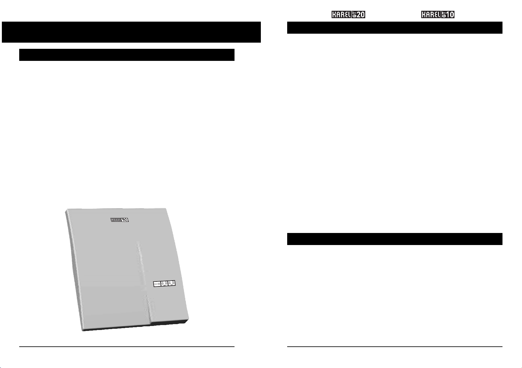
Appearances of GT20 is as follows.
Figure-1
As well as providing cost savings for GSM calls that the extensions of the exchange to
which it has been connected, GT20/GT10 also provides savings for the parties calling the
exchange over a GSM network. GT20/G10 forwards the external calls to the exchange for
the calls made over the GSM line on GT20/G10. During that forwarding, it also transmits
the CLIP information (number of the caller) to the exchange in Caller ID format upon wish.
GT20/GT10 has a structure that enables it to generate Caller ID information both in ETSI
and Bellcore standards and in FSK format. The selection between these standards are
made through programming (It has been explained in detail in next chapter.)
PART LIST ON DELIVERY
The GT20 Module includes the parts below:
1) GT20 GSM Gateway
2) PS03 Power Adaptor
3) Two External GSM Antenna
4) Mounting Template
5) Technical Reference and User’s Guide
The GT10 Module includes the parts below:
1) GT10 GSM Gateway
2) PS03 Power Adaptor
3) One External GSM Antenna
4) Mounting Template
5) Technical Reference and User’s Guide
1
2
Page 6
TECHNICAL REFERENCE AND USER’S GUIDE REV A
GSM GATEWAY
POWER SUPPLY
The GT20/GT10 power supply - PS03 -, is an external power supply that has been
designed to operate on 230 VAC /50 Hz. mains supply. This adaptor turns the mains
supply into 48 VDC and transfers to GT20/GT10 via the corresponding connector.
GT20/GT10 turns the 48 VDC it has received from the adaptor to + 5 VDC, -48 VDC and 67
Vrms ring signal by the power-processing unit it includes.
Appearance of the PS03 power adaptor is seen in the figure below:
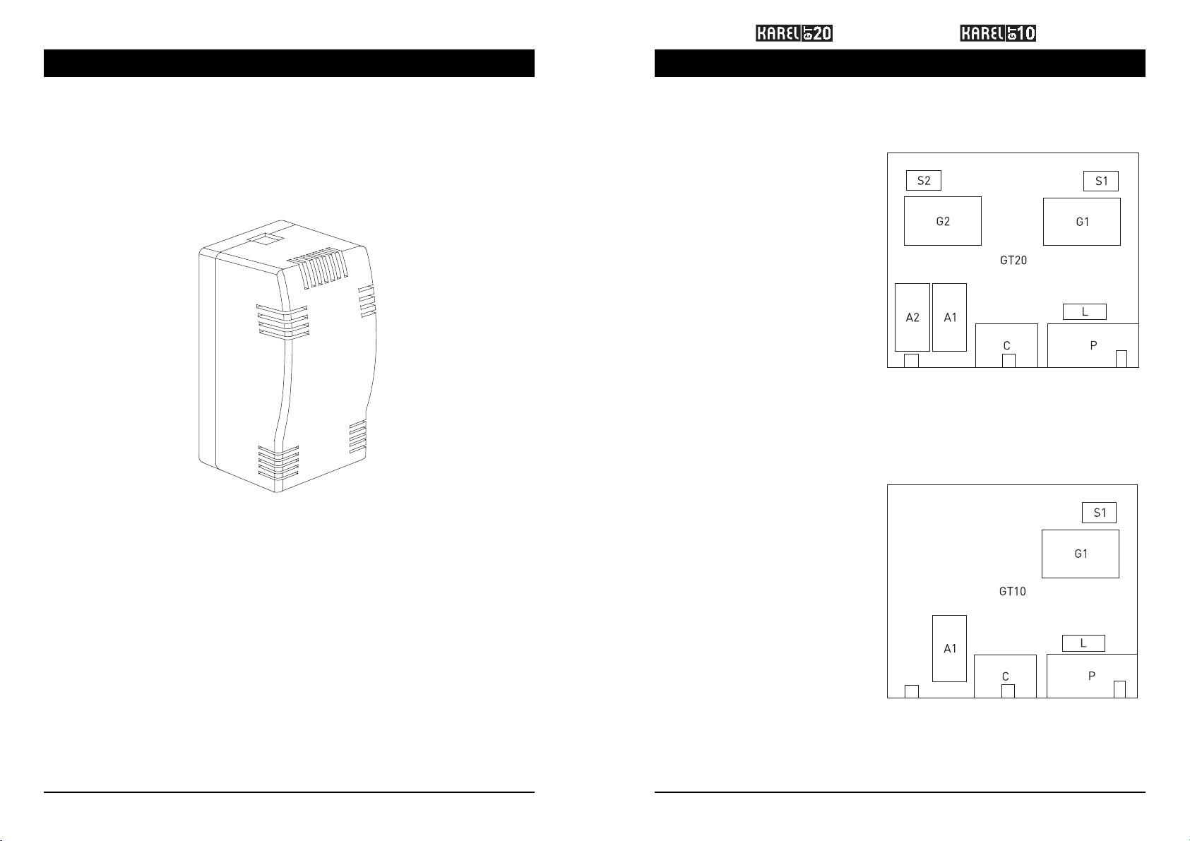
GT20 AND GT10 MOTHERBOARD
The GT20 motherboard is a card that contains on it two GSM modules, two SIM card
ports, two extension units, power processing unit, interfaces for connections, two external antenna inputs, processor that controls functions of all those units and auxiliary circuits. See the figure below for circuit locations.
S1: SIM slot for GSM module 1,
G1: GSM module 1,
A1: Analog extension for GSM module 1,
S2: SIM slot for GSM module 2,
G2: GSM module 2,
A2: Analog extension for GSM module 2,
C: Computer interface (reserved for
future use),
L: LED card,
P: Power circuitry,
Figure-3
The GT10 motherboard is a card that contains on it one GSM module, one SIM card
port, one extension unit, power processing unit, interfaces for connections, one external
antenna input, processor that controls functions of all those units and auxiliary circuits.
See the figure below for circuit locations.
Dimensions of PS03 are 11 cm. x 6 cm. x 8 cm. and it weighs 0.2 kg.
Figure-2
3
S1: SIM slot for GSM module 1,
G1: GSM module 1,
A1: Analog extension for GSM module 1,
C: Computer interface (reserved for
future use),
L: LED card,
P: Power circuitry,
Figure-4
Besides, there is a LED group which can be seen from outside even when the plastic
cabinet is closed and which gives information about the operation of the module to the
users. Order of the 5 LEDs that are on the motherboard and their functions have been
given in the foolowing section:
4
Page 7

TECHNICAL REFERENCE AND USER’S GUIDE REV A
LED DISPLAY
This figure is used also in the system cabinet just above the motherboard as a reminder.
Figure-5a
GSM GATEWAY
On/Off-4: It is turned on and off with the rhythm 250ms ON 250ms OFF 250 ms ON 250ms
OFF 250 ms ON 750ms OFF.
Figure-5b
Notes on the LED statuses:
• When GT20/GT10 is powered, the leftmost green power LED is turned on. The four
LEDs signifying the statuses of channels light in red and green until the PLD on the
card is loaded (approximately 20 secs.)
• After the PLD has been loaded, communication is established with the GSM module,
the module is reset and the required parameters are loaded. (Start-up state.)
• Even though the signal is above a certain level, the channel may be in “No network”
status. This indicates that the module has not been able to connect to the GSM
network. In such a case, while LED12 / LED22 is continuously red, it will signify the
signal level through the green color. As an example, if the signal level is “Weak”,
then while the red is continuously on, the green will light for 250 ms once every 2
seconds.
On/Off-1: It is turned on and off with the rhythm 500ms ON 500ms OFF.
On/Off-2: It is turned on and off with the rhythm 250ms ON 1750ms OFF.
On/Off-3: It is turned on and off with the rhythm 250ms ON 250ms OFF 250 ms ON 1250ms OFF.
5
IMPORTANT
Since GT10 is a single-channel device, the explanations for LED 21 and LED 22 in
the table that shows LED statuses do not apply for GT10.
The GSM modules on the motherboard support many features that a standard mobile
phone supports and these features can be presented into use through programming on
GT20/GT10.
Dimensions of the motherboard are 16.7 cm - 21 cm and it weighs 0.5 kg.
6
Page 8

TECHNICAL REFERENCE AND USER’S GUIDE REV A
TECHNICAL SPECIFICATIONS
GSM GATEWAY
Parameter is needed / confirmation tone: 150 ms 500 Hz. It is heard when a parameters
needed to be entered or a correct programming action has been taken during
programming.
Error tone: 600 ms 1200 Hz. It is heard when the PIN code has been entered incorrectly.
7
8
Page 9

TECHNICAL REFERENCE AND USER’S GUIDE REV A
GSM GATEWAY
INSTALLATION
Since GT20 and GT10 are structurally completely the same and only the number of
channels is different, the installation information below has been given for GT20.
Installation of GT10 can be carried out similarly by making use of that information for
only one channel easily.
PREPARATION
Before starting with the installation of the gateway, the location where the installation
will be performed should be determined according to the criteria below:
1- The wall on which the GT20 GSM Gateway will be mounted should be firm enough
to carry the anchor plugs and it should have a smooth surface.
2- It should be installed in places that are not exposed to direct sunlight with humidity
rate in the range %0-%80, with environmental temperature in the range 0-45°C,
well ventilated, well lit. It should not be exposed to effects of dust, vibration, oil and
water.
3- Devices that generate high frequency waves (such as welding machines, office
equipment such as computers and telex machines, air conditioners, TV sets, etc.)
should not be in the same room if possible, and they should be at least 3 meters
away from the gateway, otherwise.
4- A location with powerful GSM coverage should be chosen. As single line telephones
or telephone systems may be affected by the signal level of the GSM gateway, it is
recommended to select a place for GT20/10 far away from these equipments.
5- The mains supply should be reserved for the module only. The power supply of the
system should be uninterrupted and, if possible, the system should be powered
from an independent source from which no other device is powered.
APPLICATION
In order to mount the GT20 GSM Gateway on the wall, the front cover of the gateway
should be removed. In order to open the front cover, one should split the front cover from
the back one by pressing the latches at both sides of it. (Figure - 6).
Figure-6
After the cover of the module has been opened, the wall mounting can begin. At this
stage, the steps below should be followed.
Normally, it is not necessary to remove the card from the cabinet for the installation.
But if required for any reason, the card can be removed by following the steps in Figure
- 7. Push the latch as “1”, then move the card in direction “2” and remove the card in
direction “3”.
POWER SUPPLY THAT IS INTERRUPTED FREQUENTLY MAY AFFECT
NORMAL OPERATION OF THE SYSTEM!
6- A location that can be reached easily should be chosen, considering the mounting
work and later maintenance work.
7- There should be an outlet 2 meters away for the adaptor.
8- It is recommended that the lower edge of the module should be 150 cm. above
the floor.
9
Figure-7
10
Page 10

TECHNICAL REFERENCE AND USER’S GUIDE REV A
GSM GATEWAY
1. Location of the gateway on the wall is determined through the mounting template
and screw spots are marked.
2. The anchor plugs are inserted into the marked spots. (Figure-8.a)
3. Screws are driven so as 7-mm section of their heads will extend out of the wall
(Figure-8.b) (Height of the screw heads could be checked with the edge of the
mounting template.)
Figurel-8
4. The upper screw will be held corresponding to the upper screw slot at the back of
the module and hanged by pulling the module downwards (Figure-9). In the
meantime lower edge of the back cover is risen up so that the other screw would not
prevent the motion of the box.
5. When the upper screw has come to the highest point, the lower screw is attached to
its slot by turning the lower cover slightly to the right (Figure-10).
Figure-10
6. Perpendicularity of the module according to the floor is adjusted by sliding the
lower cover in the right-left direction and then the gateway is fixed to the wall by
tightening the lower screw (Figure-10).
7. Cover of the module is replaced after the SIM cards have been placed and
connections of the electric installation and peripheral units have been made.
PS03 POWER ADAPTOR CONNECTION
The PS03 power adaptor has been designed so as to be mounted on the wall, between
the module and the outlet. The electric plug extending out of the adaptor is plugged in an
outlet whose output voltage would not be affected by environmental factors. The module
connection is made by plugging the jack at the end of the power connection cable coming
out of the other side into the POWER input on the module.
Figurel-9
11
Lengths of cables should also be taken into consideration while mounting the adaptor on
the wall. Length of the cable between the adaptor and the module is 50 cm. and length
of the cable between the adaptor and the outlet is 200cm.
The adaptor is mounted 25 cm. away from the module, in the lower left direction.
After inserting anchor plug and the screw, which are within the adaptor box, in the wall
at appropriate distance, the adaptor is hanged on that screw.
12
Page 11

TECHNICAL REFERENCE AND USER’S GUIDE REV A
GSM GATEWAY
PLACING THE SIM CARDS
There is a SIM card slot on GT20 for each GSM module. The SIM cards are attached
to these special slots. The illustration below shows locations of the SIM card slots and
placement of the cards to these slots.
Figure-11
If the mains voltage is not constant and voltage variations are in a wide range, then a
voltage regulator between mains output and the Power Adaptor should be introduced
in order to maintain normal operation. There is a fuse of T - Type 250 V / 630 mA at the
alternative current input of the power supply. (T 630 mA L 250V).
13 14
Figure-12
Pressing the button shown as “A”, the SIM cover shown as “B” is removed. The SIM card
is placed properly on the panel shown as “C”. The cover “B” is pushed in place to finalize
the installation.
Page 12

TECHNICAL REFERENCE AND USER’S GUIDE REV A
GSM GATEWAY
TELEPHONE OR EXCHANGE EXTERNAL LINE CONNECTION
There is a clip-type socket on GT20. The two-wire cable coming from telephones or the
external lines of the exchange is connected to the clip-type connectors with springs that
are on the GT20/GT10 card. That connection has been illustrated in the figure below.
EXTERNAL ANTENNA CONNECTIONS
The external antennas that come with GT20 should be connected to the connection
points that have specially designed for them. The cable length of the external antennas
is 2 meters. The antennas that will be employed should be fixed as far away from each
other and GT20 as possible in order not to affect each other. Because of the similar
reasons, it is recommended that GT20 and the antennas should be installed away from
the exchange and telephones.
WARNING
THE ANTENNAS THAT ARE CLOSE TO EACH OTHER OR GT20 MAY CAUSE NOISE TO BE
HEARD DURING CONVERSATIONS.
While determining the locations for the external antennas and GT20 choosing locations
where GSM coverage is powerful is essential for the quality of conversations. In this regard,
it is recommended that the installation should be made to spots that are close to the outer
front of the buildings and the external antennas should be attached to the outer front walls.
The connections of the external antennas to GT20 are shown in Figure -11.
The metal holders for the external antennas are installed on the sites determined with
respect to the constaints explained above. If the site has a clean and smooth surface, the
paper at the back of the holder is removed and the holders are sticked on the surface. If
the surface is dusty and shaggy (rough plaster, wooden etc.) then the holders are fixed
with the screw pair given with the antennas.
Figure-13
GT20 can be connected over 0.5 mm copper cable at distances up to 2 kms from the
exchange or telephones.
15 16
Figure-14
After making all these connections, the front cover of the module is closed.
After that stage, some operations may be carried out in order to check the statuses of
installation of the GT20 GSM Gateway and GSM network signal level. For that reason,
primarily, while GT20 is operating, as will be explained in the next chapter, the PIN
codes must be entered to the SIM cards on GT20. Then the signal level should be
observed by the LEDs on the front cover according to the locations of the external
antennas. If the LEDs signifying the signal level are blinking fast, then this indicates
that the installation has been accomplished and the GT20 GSM Gateway is ready for
communication programming.
Page 13

TECHNICAL REFERENCE AND USER’S GUIDE REV A
GSM GATEWAY
PROGRAMMING
GT20/GT10 GSM Gateway has a flexible structure, thanks to its software features
and abilities of GSM modules. These features can be adjusted according to customer
demands through programming.
Programming of both of the GSM modules that are on the gateway are carried out
through analog lines that have been reserved for them. That is, programs should be
entered separately for each GSM module.
By entering the programming features specified here through two different analog lines
for both modules of GT20, the same or different configurations can be formed for two
GSM modules. The programming of GT10 is made over the corresponding analog line
connection.
If GT20/GT10 has directly been connected to the telephone, then that telephone must
be DTMF. If GT20/GT10 has been connected to an external line of an exchange, then
programming can be done through an extension of that exchange by accessing the
corresponding line. In that case, the external line of the exchange must be in DTMF
signaling mode.
The continuous dial tone heard when the GT20/GT10 programming starts turns into a
discontinuous dial tone with special rhythm.
Moreover, a confirmation tone is received when a parameter is supposed to be entered
during program entry and when the program code is successfully entered.
On the other hand, error tone is received when a mistake is made during program
entry.
Detailed information about cadences and frequencies of these sounds can be found in
the chapter “Technical Specifications” in this guide.
Putting the GSM Module into Programming Mode:
In order to initiate the programming, first of all, the GSM module is put into the
programming mode through this program.
Default:
Programming mode is not active.
Notes:
During the programming mode, if no program entry is done for one minute, then the
module is automatically taken out of the programming mode and the programs are
saved. Following each successful program entry, that one-minute duration starts again.
Taking the GSM Module Out Of Programming Mode:
The module must be taken out of the programming mode, in order to terminate
programming and storing new parameter values into the memory.
Automatic PIN Code Entry:
Thanks to this program, if there is a stored PIN code in the system memory, then when the
module is turned off and on again, the PIN code entry for the SIM card is done automatically.
Parameters
P : 0 Automatic PIN code entry is not on line
: 1 Automatic PIN code entry is on line
Default
P = 1
Notes:
• While this feature is active, when the module is put on line, if there is a PIN code stored
in the non-volatile memory of the module, the processor transmits that PIN code to the
GSM module. If the PIN code entry is unsuccessful (incorrect PIN code), a second try is
not performed (in order not to lock the SIM card) and the PIN code is supposed to be
entered through telephone.
• If this feature is not active, even if there is a stored PIN code in the non-volatile memory,
that PIN code is not transmitted to the GSM module, one is supposed to enter the PIN
code through telephone.
• During the first installation of the module, since there cannot be any stored PIN code in
the non-volatile memory, a PIN code will have to be entered when the SIM card is
installed and the device is put to operation. If the entered PIN code is a valid one, then
it is saved into the non-volatile memory and since the automatic PIN code entry feature
is active at the beginning, during later on/off operations, the module wall operate without
entering the PIN code.
• During normal operation, if the SIM card in one of the channels is supposed to be replaced:
a. The module is put into programming mode and the automatic PIN code entry
feature of the corresponding module should be deactivated.
b. After the module has been turned off and the SIM card has been replaced when
the module is powered again, the PIN code will be prompted. PIN code of the
new SIM card should be entered. Upon entering the correct code, it is saved into
the non-volatile memory.
c. After the module is connected to the GSM network and gets into normal
operation mode, it may be put into programming mode and the Automatic PIN
Code Entry feature of the corresponding channel may be activated.
877777
877778
803 P
17
18
Page 14

TECHNICAL REFERENCE AND USER’S GUIDE REV A
GSM GATEWAY
Caller ID Information:
By this program, GT20/GT10 transmits the Caller ID information for the call coming over
the GSM module to the exchange or telephone over the analog line.
Parameters
P : 0 Caller ID transmission is not on line
: 1 Caller ID transmission is on line
Default
P = 1
Notes:
• Only if there is the caller information in the incoming call, GT20/GT120 can transmit
that information to the exchange or telephone. If the number information of the caller
is blocked, then GT20/GT10 cannot generate the caller ID information, for it cannot
get the necessary information.
Caller ID Standard:
By this program, standard of the caller ID information for the incoming calls that will be
transmitted to the exchange or telephone over the analog line by GT20/GT10, is selected.
Parameters
P : 0 The Caller ID information is generated according to the ETSI
standard.
: 1 The Caller ID information is generated according to the Bellcore
standard.
Default
P = 0
Usage of the key # :
In order to make a call over GT20/GT10, the number to be called is dialed. If no other
number is dialed for a certain period, then GT20/GT10 initiates the call with the numbers
dialed so far. In order to initiate the call without waiting period, the key # can be employed.
When the # is dialed, GT20/GT10 initiates the call by using the numbers dialed so far.
804 P
805 P
811 P
Usage of the key *:
In case a mistake is made during number entry, GT20/GT10 cancels the digits dialed
so far and generates dial tone again, to enable another try by employing this key.
Parameters
P : 0 The key * cannot be employed to renew the dial tone
: 1 The key
Default
P = 1
Notes:
In case GT20/GT10 is connected to a Karel exchange, the extensions can employ the
key * to renew the dial tone of GT20/GT10 in GSM calls. However, for that case the
authorization of using the key * must be blocked for the related extensions by the
exchange.
can be employed to renew the dial tone
*
CLIP Information Transmission:
Number of the GSM module is transmitted to or hidden from the other parties in the calls
made over GT20/GT10.
Parameters
P : 0 The number is not transmitted to the other party; it is hidden (CLIR.)
: 1 The number is not transmitted to the other party (CLIP.)
Default
P = 1
Resetting Memory Tables:
Parameter changes made on GT20/GT10 can be reset to factory defaults when necessary
through this program.
812 P
813 P
841
Parameters
P : 0 The key # cannot be employed for terminating the number entry.
: 1 The key # can be employed for terminating the number entry.
Default
P = 1
Notes:
In case GT20/GT10 is connected to a Karel exchange, the extensions can employ the key
to terminate the number entry in GSM calls. However, for that case the authorization
#
of using the key # must be blocked for the related extensions by the exchange.
19
Notes:
Through this program the parameters below can be reset to their factory defaults:
Automatic PIN ode Entry Active
Caller ID Information It is generated
Caller ID Standard ETSI
Usage of the key # On line
Usage of the key * On line
Transmission of CLIP Information On line
Call Initiation Period 3 sec.
20
Page 15

TECHNICAL REFERENCE AND USER’S GUIDE REV A
GSM GATEWAY
Call Initiation Period:
In order to make a call over GT20/GT10, the number to be called is dialed. If no other
number is dialed within a certain period, GT20/GT10 initiates the call by using the digits
dialed so far. That period can be changed through this program.
Parameters
P : 1..9 Period to wait for transmitting the dialed digits (sec.)
Default
P = 3
GSM Speed Dial Memory:
A phone book can be created in the non-volatile memory of GT20/GT10 and short-coded
calls can be made over that phone book.
Parameters
P : 01..64 Phone book index
N : Telephone number with at most 11 digits
Notes:
• If the number of digits is less than 11, then the end of the number can be indicated
by the key #.
• As an example:
By dialing 843 07 8560202#, 8560202 can be entered into memory field 07.
In order to call this number:
7 At the end of the call initiation period, GT20/GT10 initiates the call from the
memory.
7# When # is dialed GT20/GT10 initiates the call from the memory.
Erasing Numbers From The GSM Speed Dial Memory:
In order to erase a number from the GT20/GT10 memory, this program can be used.
Parameters
P : 01..64 Phone book index
842 P
843 P N
844 P
Incoming Voice Level:
The incoming voice level can be adjusted for the calls made over GT20/GT10.
Parameters
P : 0..4 Incoming voice level (0 is the minimum level)
Default
P = 2
Outgoing Voice Level:
The outgoing voice level can be adjusted for the calls made over GT20/GT10.
Parameters
P : 0..7 Outgoing voice level (0 is the minimum level)
Default
P = 3
Unconditional Call Forwarding:
This program activates the feature that the entire incoming calls over the GSM module
on GT20/GT10 are forwarded to another number.
Parameters
P : 0 Forwarding is not active.
: 1 Forwarding is active.
Default
P = 0
Number Entry For Unconditional Call Forwarding:
This program stores the number to which the calls coming over the GSM module on
GT20/GT10 are forwarded.
Parameters
P : Telephone number with at most 16 digits
Notes:
• If the number of digits is less than 16, then the end of the number can be indicated
by the key #.
• Forwarding is automatically activated when the storing is performed.
851 P
856 P
896 P
897 P
21
Number Erasure For Unconditional Call Forwarding:
This program erases the number to which the calls coming over the GSM module on
GT20/GT10 are forwarded.
898
22
Page 16

TECHNICAL REFERENCE AND USER’S GUIDE REV A
GSM GATEWAY
Call Forwarding On Busy:
This program activates that the calls coming over the GSM module on GT20/GT10 are
forwarded to another number when the module is busy.
Parameters
P : 0 Forwarding is not on line
: 1 Forwarding is not on line
Default
P = 0
Number Entry For Call Forwarding On Busy:
This program stores the number to which the calls coming over the GSM module on
GT20/GT10 are forwarded when the module is busy.
Parameters
P : Telephone number with at most 16 digits
Notes:
• If the number of digits is less than 16, then the end of the number can be indicated
by the key #.
• Forwarding is automatically activated when the storing is performed.
Number Erasure For Call Forwarding On Busy:
899 P
900 P
901
Number Entry For Call Forwarding On No Answer:
This program stores the number to which the unanswered calls coming over the GSM
module on GT20/GT10 are forwarded.
Parameters
P : Telephone number with at most 16 digits
Notes:
• If the number of digits is less than 16, then the end of the number can be indicated
by the key #.
• Forwarding is automatically activated when the storing is performed.
Number Erasure For Call Forwarding On No Answer:
This program erases the number to which the unanswered calls coming over the GSM
module on GT20/GT10 are forwarded.
Call Forwarding In Unreachable Status:
This program activates that all the calls coming over the GSM module on GT20/GT10 are
forwarded to another number whenever the module cannot be reached.
Parameters
P : 0 Forwarding is not on line
: 1 Forwarding is on line
903 P
904
905 P
This program erases the number to which the calls coming over the GSM module on
GT20/GT10 are forwarded when the module is busy.
Call Forwarding On No Answer:
This program activates that all the unanswered calls coming over the GSM module on
GT20/GT10 are forwarded to another number.
Parameters
P : 0 Forwarding is not on line
: 1 Forwarding is on line
Default
P = 0
902 P
23
Default
P = 0
Number Entry For Call Forwarding In Unreachable Status:
This program stores the number to which the calls coming over the GSM module on
GT20/GT10 are forwarded whenever the module cannot be reached.
Parameters
P : Telephone number with at most 16 digits
Notes:
• If the number of digits is less than 16, then the end of the number can be indicated by
the key #.
Number Erasure For Call Forwarding In Unreachable
Status:
This program erases the number to which the calls coming over the GSM module on
GT20/GT10 are forwarded whenever the module cannot be reached.
906 P
907
24
Page 17

TECHNICAL REFERENCE AND USER’S GUIDE REV A
GSM GATEWAY
UTILIZATION
GT20/GT10 will be ready for utilization after the entire connections are completed and
programming is done.
GSM calls can easily be made by accessing the line which is connected to GT20/GT10 or
through the phone that is directly connected to the GT20/GT10.
In case GT20/GT10 used with a KAREL exchange, the LCR feature of the exchange would
make the utilization of GT20/GT10 very effective and easy. Thanks to that feature, the
extension would make calls as if they are making a normal call (without the necessity
for dialing a special line access code) and that call will be automatically forwarded to
GT20/GT10 by the exchange.
For example: Suppose that there is a GSM operator line serving both modules on GT20
with the prefix 0562 and GT20 has been connected to the lines 01 and 02 on MS48
exchange. In that case, by entering the LCR program to the exchange extensions are
automatically forwarded to the lines 01 or 02 as soon as they dial “90562” in order to
make an external line call. By this way, since the calls are made over the GSM modules
on GT20, call tolls will be much less than the calls made over normal lines. On the other
hand, when the LCR feature is not used, first of all the extension is supposed to access
the lines 01 and 02 and then dial the number. GSM calls will be made over normal lines
and effectiveness of GT20 will decrease.
Moreover, a GT20/GT10 that has been connected to Karel exchange will be able to
transmit the CLIP information to the extensions, thanks to the ID12 Caller ID unit that
will be connected to the exchange and the feature telephones that the extensions will
use. Therefore, owners of the telephone sets with displays or the Karel pager owners
will be able to see the phone number of the caller.
TROUBLESHOOTING
The GT20/GT10 GSM Gateway does not contain units that the user can directly intervene.
Yet it would be useful for the user to check for the items below in case of certain
problems and detect the source of the problem in order to increase the speed of the
technical service to be presented or solve some simple problems immediately.
Please contact your authorized reseller to get detailed information about those
services.
25
26
 Loading...