

Page 1
4 LINE LCD DISPLAY
FEATURE TELEPHONE SET
TECHNICAL REFERENCE AND USER'S GUIDE
06/2009
Page 2

1
4 LINE DISPLAY FEATURE
TELEPHONE SET
TECHNICAL
REFERENCE
AND
USER GUIDE
JUNE-2009
Page 3

2
FT10-FT20/4 TTKK- Ver. AAD-06.06.2009
KAREL reserves the right to make modifications in product features mentioned in this
document for development and improvement purposes, without prior notice. Individual
products may possess characteristics different from those that have been mentioned in
this document, due to their differences in software and hardware versions.
Version Table
Software Version
FT10-4 FT20-4
Date/Version of Guide
AAB AAB-AAC AAA/26.03.2003
ABA-ABE ABA-ABH AAB/13.02.2007
ABA-ABE ABA-ABH AAC/04.09.2007
ABF ABK-ABM AAD/06.06.2009
Page 4

3
ISSUES TO PAY ATTENTION TO
• Read this guide carefully before you use your device and keep it for later
reference.
• Any mistake with the connections in your device may damage it or your exchange.
Especially the connection to the exchange must be made by the Authorized
Technical Services. The explanations about connections in the User’s Guide have
been intended to give information only.
• A connection box comes with your device. The connections must be made as
described in the installation chapter.
• In case you need a connection of plug-outlet type, never apply electric plugs and
outlets; use plugs, outlets and connection components that are specific to
telephones.
• Do not make any connection other than the extension connection of the KAREL
telephone system.
• There is no part that you can repair or maintain in your device; therefore call the
authorized technical service in case of any malfunctio n.
• Keep your device away from direct sunlight.
• Do not let any liquid substance spill on your device.
• Do the exterior cleaning of your device with a slightly moistened piece of cloth.
• Do not apply an y chemica ls for cleaning.
• Please call your authorized dealer in case you would like to change the place of
your device. Use its own packing to carry the device.
Page 5

4
PREFACE
Chapters in this guide have been prepared in order to present detailed technical
information to people who need technical-introduction-based information about the
FT10 and FT20 4 Line Display Feature Phones, in addition to giving technical
information about programming and use of those telephones. By this way, one could
understand abilities of the FT10 and FT20 4 Line Display Feature Phones, how it will
be operated in accordance with customer demands and things that should b e done in
order to operate them with full performance.
The first chapter - “Technical Introduction” – It contains technical information about the
hardware and software structures of the FT10/20 Feature Phone. Information in this
chapter, for which knowledge in mechanics, electricity and electronics may be
prerequisite, aims to introduce structure of the phone.
The second chapter – “Installation” – The methods to be followed for the installation of
the FT10/20 Feature Phone are explained. This chapter must be rea d definitely before
the installation by the personnel who will perform the installation.
The third chapter – “Utilization Features” – This chapter gives pratical information
about the usage of FT10/20 Feature Phone.
The fourth chapter – “Program Features” – This chapter gives detalied information
about the software features that will enrich functions of the FT10/20 Feature Phone
and that could be applied to meet daily communication needs of customers more
comprehensively.
The last chapter – “Accessories” – It gives short information about the accessories
which are used with this FT10/20 Feature Phone.
Best Regards,
KAREL
Page 6

5
CONTENTS
TECHNICAL INTRODUCTION .........................................................................7
INTRODUCTION............................................................................................7
COMPATIBILITY............................................................................................7
PARTS LIST ON DELIVERY .........................................................................7
GENERAL APPEARANCE ............................................................................8
TECHNICAL SPECIFICATIONS....................................................................8
USER INTERFACE........................................................................................9
DISPLAY....................................................................................................9
DISPLAY KEYS .........................................................................................9
SPECIAL FUNCTION KEYS....................................................................10
NUMERICAL KEY PAD...........................................................................13
VOICE CONTROL KEYS.........................................................................13
SPEED DIAL KEYS .................................................................................14
FUNCTION PROGRAMMING FOR THE SPEED DIAL KEYS...............15
By the Function Programming Menu: FT10 and FT20......................................15
Code Programming:..........................................................................................17
By the Private Pool Programming Menu: FT10.............................................17
By the Feature Code Programming Menu: FT20..........................................18
By Automatic Programming Menu: ...................................................................18
INSTALLATION...............................................................................................19
CONNECTION POINTS...............................................................................19
FT10 INSTALLATION..................................................................................21
Required Hardware For The Connection:.........................................................21
Connecting FT10 To The Exchange:................................................................22
Defining Extension Number For FT10...............................................................25
Number Of FT10s That Can Be Connected To The Exchange And Connection
Distances..........................................................................................................25
FT10 Start-up State ..........................................................................................26
FT20 INSTALLATION..................................................................................27
Defining Extension Number For FT20...............................................................30
Number Of FT20s That Can Be Connected To The Exchange And Connection
Distances:.........................................................................................................30
FT20 Start-Up State..........................................................................................30
UTILIZATION FEATURES..............................................................................32
DEFAULTS AND ACTIVE SERVICE INFORMATION ................................32
CONVERSATION FEATURES:...................................................................37
PROGRAM FEATURES..................................................................................42
PROGRAMMING MENUS...........................................................................42
CALL OPTIONS...........................................................................................43
Call Diversion ...........................................................................................43
Auto Dial...................................................................................................43
Paging.......................................................................................................44
Page 7

6
Missed Calls .............................................................................................44
Answered (FT20)......................................................................................44
Dialed (FT20)............................................................................................44
PHONE SETTINGS .....................................................................................45
Key Settings..............................................................................................46
Extension Programming....................................................................................46
Line Programming.............................................................................................47
Private Pool Programming................................................................................48
Common Pool Programming.............................................................................49
Feature .............................................................................................................49
Feature Code [FT20].........................................................................................50
Auto Settings.....................................................................................................50
Do Not Disturb..........................................................................................53
Music (FT10).............................................................................................54
Reminder..................................................................................................54
EPROM Version.......................................................................................54
Lazy Mode................................................................................................54
Private Pool Entry (FT20).........................................................................55
Language..................................................................................................55
Headphone...............................................................................................55
Signal Beep Option...................................................................................55
Price (FT20)..............................................................................................55
Home Area Code (FT20)..........................................................................56
Line Access Code:....................................................................................56
PHONE SECURITY.....................................................................................58
Password..................................................................................................58
Phone Lock...............................................................................................58
Phone Unlock...........................................................................................58
MESSAGE....................................................................................................59
Absent Message:......................................................................................59
Message Listen: .......................................................................................59
SYSTEM SETTINGS ...................................................................................60
Setting Time..............................................................................................60
Setting Date:.............................................................................................60
Night Mode: ..............................................................................................60
Common Pool Entry: ................................................................................60
ACD:.........................................................................................................61
Parallel Operator: .....................................................................................61
PHONE BOOK.............................................................................................62
Find...........................................................................................................63
Add ...........................................................................................................63
Change.....................................................................................................63
Delete .......................................................................................................64
APPENDIX:..................................................................................................66
Error Messages ........................................................................................66
ACCESSORIES...............................................................................................67
Page 8

7
TECHNICAL INTRODUCTION
INTRODUCTION
FT10 is a telephone set, which can be used with all MS series exchanges of KAREL,
and that provides ease and rapidity to the usage of those s ystems.
NOTE: FT10 is not compatible with the MS26S exchange, as an exception.
FT20, on the other hand, is a telephone set, which can be used with the entire DS
series exchanges of KAREL and whose utilization characteristics are significantly
similar to that of FT10. Differences between the t wo products arise from the fact that
the features supported by the DS and MS type exchanges are different. Those facts
have been specified in the guide; they are supposed to be considered during usage.
By the FT10 and FT20 telephone sets:
• Users are provided with the facility of performing sever al operations such as calling
back, auto dialing, follow me, conferencing and alarm setting, by pressing a single key
through special-purpose keys and the display that are on the telephone, without the
necessity to know the system-specific special codes.
• Active services and call information, as well as the actions that the user can take for
them, are displayed through the four-line LCD (liquid cr ystal).
• Actions that can be taken for the active services and the call information, which are
indicated on the LCD display, are carried out easily and rapidly through four keys with
special functions that are located below the display.
• One-touch extension and/or line calls can be made over the phone book and
programmable keys. (This facility is valid or MS Series software with the version ACA
or better.)
• Statuses of the extensions and/or lines that have been assig ned to those keys can be
viewed through the lights (LED) in two colours, which are embedded into the
programmable keys.
COMPATIBILITY
The FT10 telephone set is compatible with the 3.11H or better software of the
exchanges of models MS26C, MS38S, MS48, MS48S, MS48C, MS128 and MS224.
The FT20 telephone set is compatible with the entire versions of the exchanges of
models DS200, DS200S and DS200M.
PARTS LIST ON DELIVERY
Parts that are included in the FT10 or FT20 package:
• FT10 or FT 20 telephone,
• Handset,
• Spiral cable of the handset,
• Data cable with RJ11 connectors at two ends,
• Console connection box,
• Technical Reference and User Guide,
Page 9
8
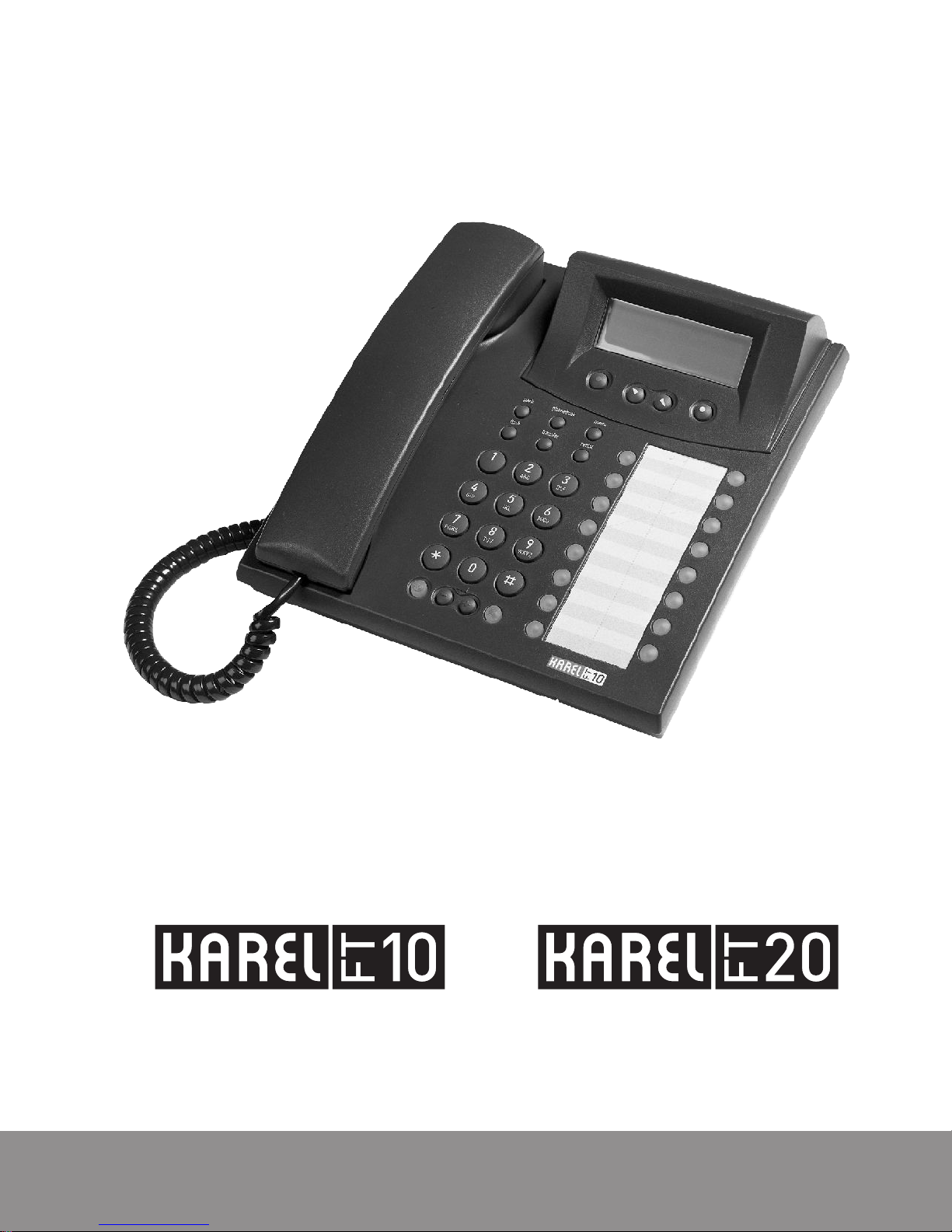
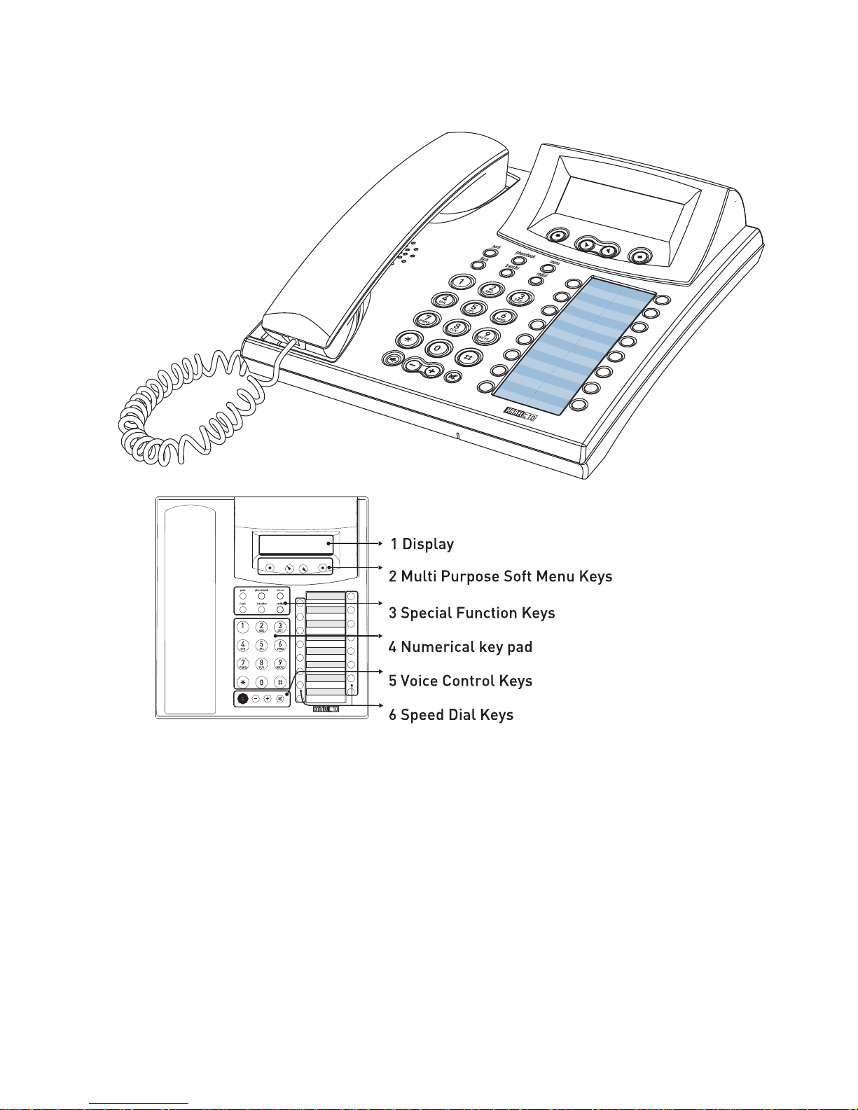
GENERAL APPEARANCE
TECHNICAL SPECIFICATIONS
Weight: 900 gr
Dimensions: 217 mm x 229 mm x 86 mm
Operational Temperature: 5 oC - 40 oC
Storing Temperature: -20
o
C - +60 oC
Humidity: 0 - %80
Dialing Method: DTMF (Tone dialing)
Page 10
9
USER INTERFACE
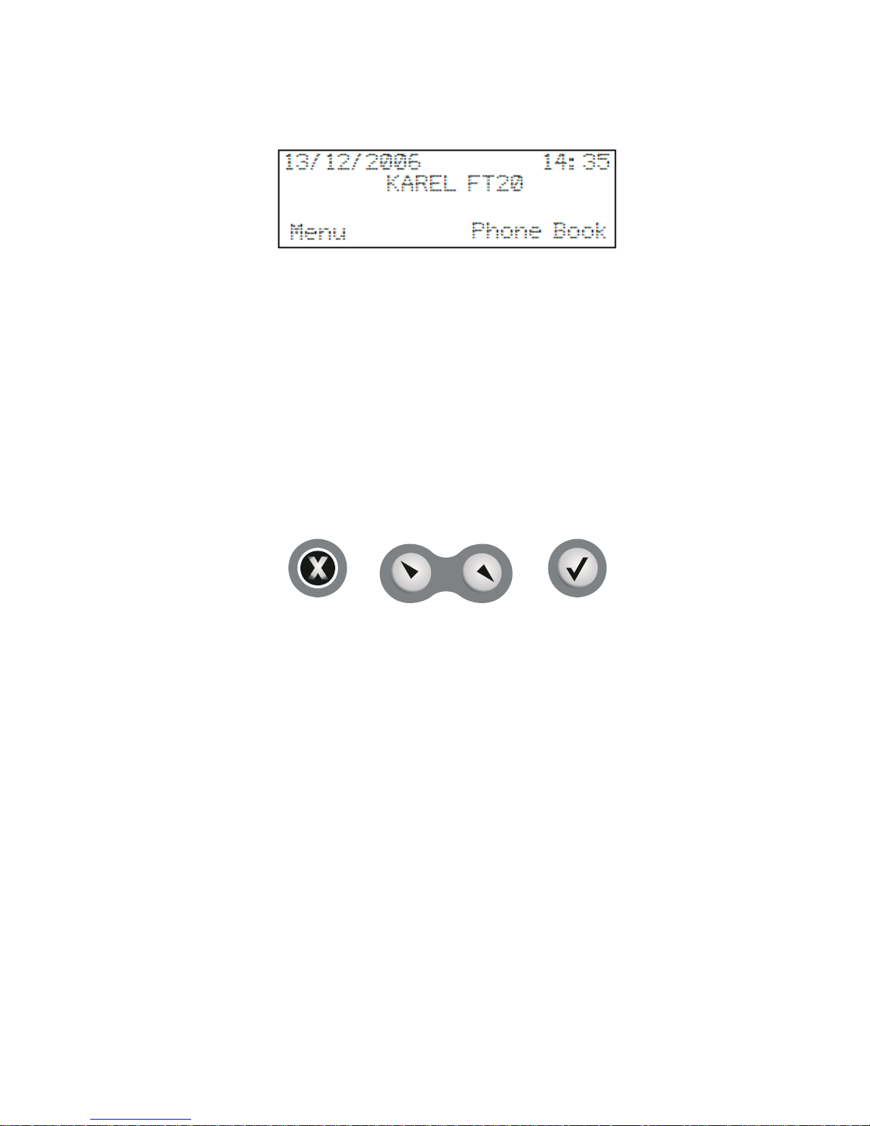
DISPLAY
Information presentation display is of four lines with 20 characters. The following
information that facilitates usage is present on the LCD display, which indicates the
active features of the telephone and the functions of the flexible keys at that moment:
• Date, time
• Entry to the menu options, phone book
• Activated services (such as Auto-dial, Follow Me and Redial)
• Call information [FT10] (Incoming Call Extension 121, Missed Call E 121 1/0 1)
[FT20] (Incoming Call Extension 1444, Missed Call E 1444 1/01)
• Action options that can be taken for the active call and service
[FT10] (Such as Redial / Call, Missed Call E 113 Details?)
[FT20] (Such as Redial / Call, Missed Call E 1444 / Details?)
DISPLAY KEYS
These keys are located below the display and they play an important role in usage of
FT10/20.
Actions that can be carried out and/or information that can be received by a user while:
- a call / conversation is being made
- the telephone is being programmed
- the telephone is on hook
are presented through the display. In order to carry out these actions and/or access
that information, the keys are pressed according to the options on the display.
These keys are used for accepting or declining the alternatives prese nted to the user
on the display at that moment, or they are used for accessing new alternatives.
Functions that will be activated by those keys or title of the information to be accessed
are indicated on the display. Such a display will be actualized only if there exists a
function programmed on the key or information to be accessed through the key. For
example, if there are options not more than two, then the navigation keys do not
function.
Selection Keys:
They are used for confirming and activating the case indicated right at the top of the
display at that moment. For instance, for FT10, the options “menu” and “phone book”
appear on the display of the telephone dur ing off-hook status, above these keys. Any
desired option could be confirmed through these keys and access to submenus is
provided. Function of the selection keys change according to the options prompted on
the display.
Page 11

10
Navigation Keys:
While in programming mode, left navigation key provides access to the previous ma in
menu if it is pressed on main menus, and if it is pressed on submenus, then the entire
options in that submenu are displayed. Starting from the first submenu do wn to the last
one, the entire options can be easily reached; moreover, one goes back to the first
submenu again after the last one, without exiting to the main menu. However, if the
“Exit” option is confirmed through the right selection key, then one goes back to the
main menu, where those options are located. While making chan ges in the content of
the phone book, as the cursor shifts one digit back, the entry is erased by one
character on each move.
By the right navigation key, one proceeds to the next menu or message from all me nus
in cases when the “
> ” sign appears on the display. The entire main menus starting
from the first one down to the last are displayed and then one returns to the first main
menu again, after the last menu. It is also possible to browse the submenus, once one
has a made a selection in the main menu and has proceeded to the submenus.
SPECIAL FUNCTION KEYS
• “Park” Key: If this key is pressed during an ongoing line call, then that line is
parked. If it is pressed when there is a parked line, on the other hand, then the parked
lines are retrieved one by one.
• “Phone Book” Key: This key activates the phone book and it provides access to
the entire telephone records from that.
•
“Menu” Key: This key activates the menus by which the telephone is progr ammed
and it provides access to the submenus.
•
“Flash” Key: It puts an ongoing external or internal call on hold or puts a line on
hold back to conversation mode.
•
“Transfer” Key: It functions the same as hanging up and then picking up phone.
While there is a line on hold, it transfers the other ongoing call to the line on hold.
•
“Redial” Key: This key dials again the last external number that has been called.
Park:
A line or an internal conversation can be parked by pressing this key during the
conversation. If it is pressed when there is a parked line, then it puts the parked line
into conversation mode. Likewise, if this key is pressed when there is a parked internal
call, it puts the internal call into the conversation mode. When the call is parked by
using that key, “parked line” information and “Retrieve” option for the lin e appear on the
display. The call can be retrieved by pressing th e right selection key or the “Park” key
for a second time. A call can be parked more than once and more than one line can be
parked at the same time. When a line has been parked, the telephone can be used
independently from that external conversation, i.e., internal and external calls can be
made by making use of the entire features.
Page 12

11
A call can be parked more than once and more than one line can be parked at the
same time. When a line has been parked, the telephone can be used independently
from that external conversation, i.e., internal and external calls can be made by making
use of the entire features. For FT10/20 Feature Phone users, if there are parked line
and also parked internal call and if the other service is activated, the inter nal line call
will be retrieved in turn with this key.
The first call which is parked will be displayed in the first rank of the park list.
The second function of this key is, on the other hand, providing the relation bet ween
the exchange and the console. The key is employed when it is required to change the
number of the telephone or to reset the connection to the exchange. When the key is
pressed until the “beep” is received and then it is released, the tele phone prompts for
the extension number to be put on the data line of the exchange.
In order to enter the “terminal no=aa” value of FT10, this key is pressed consec utively
to proceed until the correct extension number is displayed and the extension number
will have been entered to the telephone upon lifting and then replacing the handset.
As FT20 is concerned, the extension numb er, “telephone number, no=aaaa” is enter ed
according to the numerical values that have been assigned to the programmable keys
and then the number is detected by the exchange upon pressing the “Connect” key.
(Those numerical values have been explained in detail under the title FT20 Factory
Default.)
* For FT20, it should be used when a new num ber is defined for the tel ephone or when
the FT20-exchange connection is desired to be reset.
Phone Book:
This key provides access to the telephone book, which has been created through the
main menus that have been accessed by using the “Menu” key or its option on the
display, which contains names and phone numbers and over which operations on
those entries could be carried out.
If there is any record in this phone book, then those records, which are in alphabetical
order, are directly displayed. The records that are present in the teleph one at that time
can be directly searched by name or number query through the “Find” option on that
display. (The phone book is empty at the first use of the telephone.) T he other records
can be displayed by the navigation keys. (On F T10 telephones, no calls can be made
through the "Phone Book/Find" option.)
Besides, the “Find”, “Add”, “Change” and “Delete” options can be accessed over the
navigation keys after selecting the “Up” option that is on the dis play. The other records
can be displayed through the navigation ke ys. In the event that there is no record, only
the “Add” and “Change” options are displayed. The submenu title, named as “Entry
Message”, can be accessed when the “Change” option is selected and the nav igation
keys are used. The expression with at most 18 characters that is entered here will be
displayed on the display of the telephone during off-hook state. Detailed information
about the phone book has been presented in the relevant section.
Page 13

12
Menu:
It is used for doing the entire Phone Settings. T he menu is entered by pressing this ke y
and then one can proceed to the entire main menus and then to the su bmenus, and th e
navigation keys can be used for moving within those menus or submenus, if necess ary.
The telephone gets into the busy mode after the menu has been entered and it rema ins
so until the menu is exited.
Flash:
It is used for putting the calling party on hold during an internal or external call. W hen it
is pressed for a second time, the call on hold is retrieved, or the call can be retrieved by
the “Retrieve” option that appears when the key is pressed.
It drops the line when it is used while the other party has not yet picked up the phone. A
single call can be put on hold at a time. There is no limit for the duration to press the
key; however, in the event that the line that has been put on hold has not still be
retrieved at the end of a certain period that is determined by the exchange software,
the line may automatically be dropped.
Transfer:
It is used for transferring an ongoing call to another call that is on hold. In order to
actualize the transfer operation, first of all the conversing party should be put on hold
by using the flash key or the “Hold” / “Park” option on the display. Afterwards, the
number to which the transfer operation will be done is dialed. At this point, the
operation is accomplished by pressing the transfer key before or after conversing with
the extension to which the call is to be transferred.
During a “Transfer” operation done over FT20/DS200:
• A line cannot be transferred to another li ne.
• If it is the FT user who has started the convers ation, then an extension cannot be
transferred to a line.
• On the other hand, if it is a line that has started the conversation, then that line can
be transferred to an extension.
Making use of the transfer option on the LCD display will also accomplish the tra nsfer
operation following the same rules above.
Redial:
It dials again the last number that has been dialed. This key functions the s ame way as
the “Redial” option on the display. The difference between “Redial” and “Auto-dial” is
that the “Auto-dial” option automatically calls the other party repeatedly until busyness
status is over (Actually, at most 16 times), whereas the “Redial” option calls only once.
When the “Redial” option is used, the line access code and the dialled number are
displayed together on FT20 display.
Page 14

13
NUMERICAL KEY PAD
It is composed of 3x4 (DTMF) key matrix. Moreover, these keys are used for number or
character (letter, figure or symbol) entry during the operations related to the “Phone
Book”. Grouping of the characters with respect to the keys are as follows. Standards
that apply for similar applications have been complied with for this subject. If any
programmable key is pressed when the letter entry is being made with capital letters,
the entry starts to be made by small letters. By the same way, if any programmab le key
is pressed again, small letters turn into the capital letters. If the small letters are started
to use the “^” is displayed on the top left side of the screen.
Group of “1”: (space) 1 $ % &
Group of “2”: A B C 2 # (a b c)
Group of “3”: D E F 3: (d e f)
Group of “4”: G H I 4 - (g h i)
Group of “5”: J K L 5 ( (j k l)
Group of “6”: M N O 6 ) (m n o)
Group of “7”: P Q R S 7 (p q r s)
Group of “8”: T U V 8 + (t u v)
Group of “9”: W X Y Z 9 (w x y z)
Group of “0”: 0 → ! ? =
VOICE CONTROL KEYS
Control of voice features of FT10 and FT20 telephon es are fulfilled by making use of
four keys:
“I” Key: (Handsfree: It is a feature of telephone that it emits voices into the room or
transmits voices inside the room to the other parties while the handset is still on hook.)
This is the key with a red icon that puts the telephone into the “handsfree” status and
that signifies this through an embedded LED. The key is called H/F key, and the LED
inside it is called H/F LED.
Page 15
14
I
Key performs different functions in different cases. These are:
• When it is pressed while the handset is on hook, the telephone is picked up as
“handsfree” and the H/F LED lights. In this case, a number can be dialed and a
conversation can be made without lifting the handset. Pressing the key during a
conversation terminates the conversation.
• The H/F LED starts to blink if it is pressed while dial tone or busy tone is being
received over the handset or while a conversation is being made. If the handset is
replaced before the H/F LED goes out, then one continues to receive d ial tone or
busy tone, or one can go on with the conversation. T he conversation is terminated
if the handset is replaced after the H/F LED has become off.
• If the handset is lifted during the handset status, then the rest of the conv ersation
goes on via the handset. Replacing the handset terminates the conversation.
• While the handset is on hook, in the event that this key is pressed twice
consecutively, the other party can be heard both via the handset and the H/F
speaker. The opposite party would hear the things spoken via the handset only,
but no voice would be transmitted to the opposite party via the H/F microphone.
The conversation terminates by replacing the handset at this status.
• If “Headset” usage has been activated through menu options, then this key may
also be used for putting the headset on line. Headset usage has been explained in
detail in the “Connection Points” section.
“-”Key: It is used to decrease the level of voice receiv ed during conversation in the
Handsfree mode.
“+”Key: It is used to increase the level of voice received during conversation in the
Handsfree mode.
“j” Key: The MUTE key with a black icon, which provides interruptio n of the outgoing
voices during the all conversations and which signifies that via the LED inside it.
Pressing the key for a second time will maintain the voice transmission to the opposite
party again. Please note that this key is used only during the H/F conversations. When
a conference is started through the FT20 telephone the outgoing voices can be
interrupted by pressing this “MUTE” key.
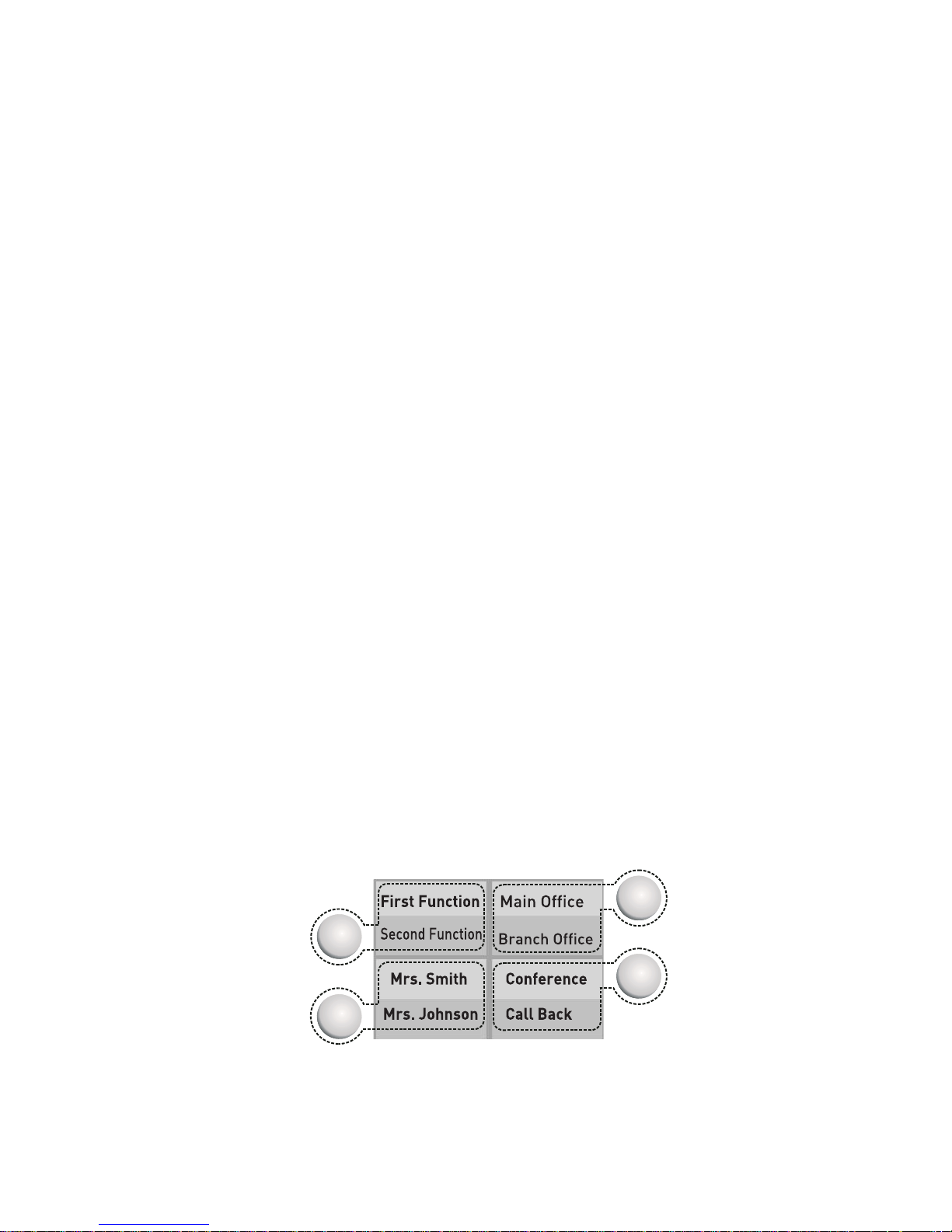
SPEED DIAL KEYS
Two functions can be programmed for each of the speed dial keys, which consist of 16
keys with lights. Features that can be assigned to these keys through programming:
• Extension Number
Page 16

15
• Line Number
• Private and Common Pool Num ber
• Function Services (Services such as Follow Me, Call Back, Do Not Disturb,
Telephone Lock, Conference, Night Mode)
• [FT20] Feature codes (DS20 0 programming and user codes, such as entry to
programming by the code 877777, Do Not Disturb function by the code 831.)
These assignments are done to the first or the second functions of the key during the
program entry done by pressing the “menu” option. Assignment is done to the first
function if the key is pressed for a short time, and it is done to the second one if the key
is pressed for a longer period. Transition of the key to the first or second function is
indicated by a short or a long beep, respectively. Besides, the LED that belongs to the
key lights in green for the first function and lights red for the second one during
programming.
When the keys that have been programmed for extension, line, pr ivate or common pool
are pressed, these numbers are called directly. When the keys that have been
programmed for the services such as Follow Me and Call Back are pressed, these
services are activated directly or a necessary input is prompted. (Such as the e xtension
number, to which the Follow Me action will be carried out.)
When the keys, to which “User Code” has been numerically assigned, are pressed, the
service that has been determined through the user code is activated directl y or the
appropriate code is prompted. The Follow Me service (85) and the extension number to
which the forwarding will be done would constitute an example for that kind of usage.
FUNCTION PROGRAMMING FOR THE SPEED DIAL KEYS
This feature provides for taking advantage of some functions that have bee n define d for
FT10 and FT20 in the exchange properties, by pressing a single key. A user may
program for those keys the features presented by the Karel telephone branch
exchange, which s/he would use most frequently.
Different methods can be employed for assigning functions to the programmabl e keys
of the FT10 and FT20 feature telephone sets. These operations are carried out for
FT10 through the submenus of Function, Private Pool or Autom atic Programming in the
Phone Settings > Key Settings option. For FT20, on the other hand, they are carried
out through the submenus of Feature, Feature Code or Automatic Programming in the
Phone Settings > Key Settings option.
By the Function Programming Menu: FT10 and FT20
Features most frequently employed by users are among those options. The
programming can be carried out by assigning desired o nes out of the 10 options that
have been presented in the Key Settings > Feature submenu, in order to apply that
programming option. First the key to be used is selected, then the desired one out of
the 10 presented functions is brought to the display through the right/left navigation
keys and the programming is completed by the “Accept” key. These selections have
been explained below:
Page 17

16
• Follow Me Key: If this key is pressed while dial tone is being received and
then if number of an extension is entered, then forwarding to that extension is
actualized and then red LED lights. If it is pressed again while dial tone is being
received, then the forwarding is cancelled and the LED goes out.
•
Call Back Key: If a called extension is busy or not ans wering and if busy to ne
is received upon attempting to access a line, then that extension/line is cal led back
by pressing this key and the appropriate red LED lights (No LED lig hts on FT10.) In
order to cancel the call back operation, the key is pressed agai n while dial tone is
received and the LED goes out (No LED lights on FT10.)
• Do Not Disturb Key: It puts that extens ion into the “Do Not Disturb” mode if it
is pressed while receiving dial tone and the red LED starts to blink. In that case,
telephone rings once when the extension is called. If it is pressed again while
receiving dial tone, then the “Do Not Disturb” service is cancelled and the LED
goes out.
•
Telephone Lock Key: If this key is pressed while dial tone is being received
and then a password is entered afterwards, then the telephone will be closed for
external calls. The telephone will be open for ext ernal calls again, if the procedur e
is repeated in that mode. The corresponding red L ED is on while the telephone is
locked and goes out when it is unlocked.
• Conference Key: During a call with an extension or line, this ke y is employed
for including another extension or line into the conferenc e. If a line is desired to be
included into the conference, the line with which the conversation is g oing on is put
on hold by pressing this key and one proc eeds to conversation status with the li ne
to be included into the conference. A triple conference is established upon
pressing this key again. If it is an extension that is to be included into the
conference, then that extension is called after making hook flash during the call
with an extension or line. The triple conference will have been established upon
pressing this key, after initiating the conversation with that extension. If it needs the
“Drop” option which is appeared during the tripl e conference can be used. At the
time of conference the “Mute” key can be used in order to provid e the interruption
of the outgoing voice. During the conference with the extensions or lines the
information of the ongoing conversation of the extension or line will be displayed.
•
Night Mode Key: It can be employed only through the telephones that have
been defined as the operator. It puts the system into the Night Mode when it is
pressed while dial tone is being received and the LED will be turned on. If it is
pressed again, then it puts the system into the Day Mode and the LED goes out.
• Page Key: When this “Page” key is pressed, the first functions of the all-
programmable speed dial keys are became the second functions of the allprogrammable speed dial keys. In that case two different function statuses of each
key are displayed through the LEDs. In normal operation, the LED l ights in red for
the first page functions and lights in green for the second page functions. W hen the
green LEDs are ON, it means the second functions of the keys are active.
Moreover, when the green LED lights, the chararater “^” will be seen in the
date/time line of the display and it shows that the second functions of the
programmable keys are active. If there is a key as a “page” key and another ke y is
desired to program as page key, the first and the second functions of the old page
key is directly erased. At the first initiation of the phone, the LED of page key (if
exists) will light in red.
Page 18

17
• Auto Dial Ke y (FT10): The telephone automatically calls the corresponding
number when the auto-dialer is activated. If the called party is busy, then the
calling action is performed repeatedly in every 15 seconds. As soon as the
business of the opposite party is over, the telephone notifi es that by ringin g itself or
by short beep.
•
Message Key: If there is an EVM module placed on the system and a voice
message is left to the extension, the LED of this message key will blink to inform
the extension a new message left. All voice messages left to you can be listened
successively if the key is pressed.
• Call Collect Key (FT20): When a user is busy or in a conversation, the
incoming internal or external call can be taken by pressing this key and at that time
the first line is dropped. During a conversation, a notice tone which informs that
there is a new call, is heard. If this key is pressed, a new conversation is started
with this call and the existing call is parked.
Code Programming:
By the Private Pool Programming Menu: FT10
Twenty most frequently called external numbers can be programmed into the private
pool of the telephone. Moreover, functions supported by the exchange can also be
assigned to the keys by applying private pool programming. (Ple ase refer to the user’s
guide of your exchange for information related to the functions supported by the
exchange and the codes to program them.)
After entering “Register no=” via Key Settings > Private Pool submenu, codes of the
entire features presented to users can be programmed for the “no=” option by primarily
pressing the “*” key.
Example: An extension using the MS48 exchange can make conversation with a part y
at the door over telephone, provided that there is a door phone (the device for the
action being mentioned) connected to the exchan ge and s/he can open the door upon
wish through telephone, if the door connection has been made to her/his exchange. An
FT10 user that employs those features frequently can facilitate utilization by
programming those functions for the keys of the telephone. In order to do that, first the
user’s guide of the exchange should be referred to for information about the topics
“Door phone Conversation” and “Door Opener”. By this way, one would learn whether
the exchange code for Door phone Conversation is 110 or 10 and the code for Door
Opener is 151 or 129, as well as properties of the functions. Then, by accessing FT10
menu, submenus of “Phone Settings”, “Key Settings” and “Private Pool” are selected,
respectively. Upon the displayed warning, “Press Key”, the memory key that will be
used for door phone conversation is pressed. In case there is another function or
extension number that has previously programmed for that key, it will be deleted. Once
the key to be employed has been selected, the prompt “Register no=” is displayed.
Each user has a capacity of 20 numbers reserved for her/him. A memory number in the
range 01..20 is entered corresponding to the “Register no=” prompt on the display and
the entered value is automatically confirmed. The sign “no=” appears on the display,
afterwards. At this step, the exchange code of door phone is entered after pressing the”
*” key shortly: (*110) or (*10). The programming is completed by pressing the right
Page 19

18
selection key. The display reverts to the “Private Pool” menu. The actions explained
above are repeated for the door opener function as well; codes (*151) or (*29) is
entered, then they are confirmed by the right selection key and the operation is thus
accomplished. One reverts to the Key Settings submenu screen by pressing the “Up”
key. Then the user can talk over the door phone or open a door, each by pressing a
single key that s/he has previously chosen.
NOTE:
• The code required for “Door Phone Conversation” is 110 in the MS48 exchange,
however, capacities smaller than 6/18 require the code 10.
• On the other hand, the code required for “Door Opener” is 151 in the MS48
exchange, however, for capacities smaller than 6/18, the required code becomes
29.
By the Feature Code Programming Menu: FT20
The entire functions supported by the exchange can be programmed for FT20 feature
telephone set through the Feature code menu. Any eight-digit code can be assigned to
the programmable keys. That code could be one that is related to user, such as Follow
Me (85), one that is related to the operator, such as Wake Up Service (8389) or one
that is related to the system supervisor, such as entry to the exchange programming
(877777). If the entered code is none of them, then it is taken as an extension number
and this extension number is called directly when this key is used. After accessin g the
Key Settings > Feature code submenu, if one of the programmable keys is selected,
one of the corresponding codes is entered for the “no=” option and then if it is
confirmed through the “Accept” key, then the program will have be en assigned to the
selected key. (Please refer to the user’s guide of your exchange for information related
to the functions supported by the exchange and the codes to program them.)
By Automatic Programming Menu:
In FT telephone sets, possibility of assigning different functions to the entire keys
simultaneously is provided via the Auto Setting option under the Key Settings menu.
This feature will be explained in detail later in the section “Auto Settings”. Via the
automatic programming, about 20 functions can be pro grammed for the FT telephone
sets at the same time. These functions can be changed later one by one, as a lready
explained in the sections above, or they can be cleared through the “Clear All?” opti on
in the same menu.
Page 20
19
INSTALLATION
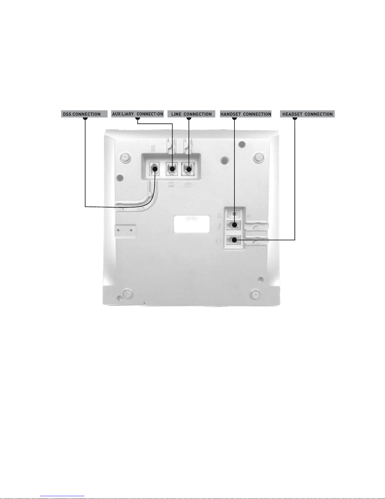
CONNECTION POINTS
Under FT10/20, there are five connections. Connections and their characteristics have
been illustrated below.
DSS CONNECTION: “Direct Station Select Unit” connection point. By employing this
connection point, the FT10/FT20 feature telephone set can be used together with
DSS10/DSS20 Direct Station Select Unit in order to make use of the exchange
features more actively.
AUXILIARY CONNECTION: The connection point that is required for pro gramming FT
over computer. It has been reserved for future use or applications.
LINE CONNECTION: Line connection point of FT.
HANDSET CONNECTION: Handset connection point.
Page 21

20
HEADSET CONNECTION:
It is employed for connecting headset option to the telephone. The standard headset
could be obtained from KAREL.
HEADSET TYPES: KAREL GLS201
• Activation of Headset: The selection is made through the PHONE SETTINGS
>HEADSET menu. (HEADSET >Disable, With HANDSFREE, Without
HANDSFREE) The headset option is in Disable mode by default.
• While telephone is on hook, when the H/F key is pressed, the tele phone is picked
up through the headset. If H/F key is pressed again, then the headset is turned off
and the telephone gets into HF mode. The telephone is hanged up, if the H/F ke y
is pressed again. During a conversation over the headset, if the handset is lifted or
if the telephone is picked up through the handset, then the voice level will
decrease, since it will be split into two.
• In order to facilitate headset utilization: PHONE SETTINGS > LAZY MODE could
be selected. In that case, the telephone is picked up automatically after the first
ringing without pressing any key and conversation goes on via the headset.
Page 22
21
FT10 INSTALLATION
In order to operate the telephone, first, the spiral handset cable is connected to the
connection point under the telephone and to the handset. Then FT10 must be
connected to the KTS line of the exchange.
Required Hardware For The Connection:
FT10 is presented to the user together with a “telephone data cable” of length 2.5 m.
and a connection box. There are 6-pin, RJ-type male connectors at both ends of the
“telephone data cable”. One end of this cable has been attached to a 6-pin, RJ-type
female connector that is on the connection box. The connector at the other end of the
cable will be attached to its correspondent under FT10. The cavity, which is on the side
of the connection box without the 6-pin, RJ-type female connector, has been left for
other cabling that would be carried out on the box. (Parallel connecti on of the DATA /
+12 VDC / GROUND (GND) signals and A / B terminal connections.)
Those signals are present on the console connection box that is included in the
FT10 hardware:
1. + 12 VDC
2. No connection
3. B (Tip) signal coming from the corresponding extension
4. A (Ring) signal coming from the corresponding extension
5. Ground (GND)
6. Data signal
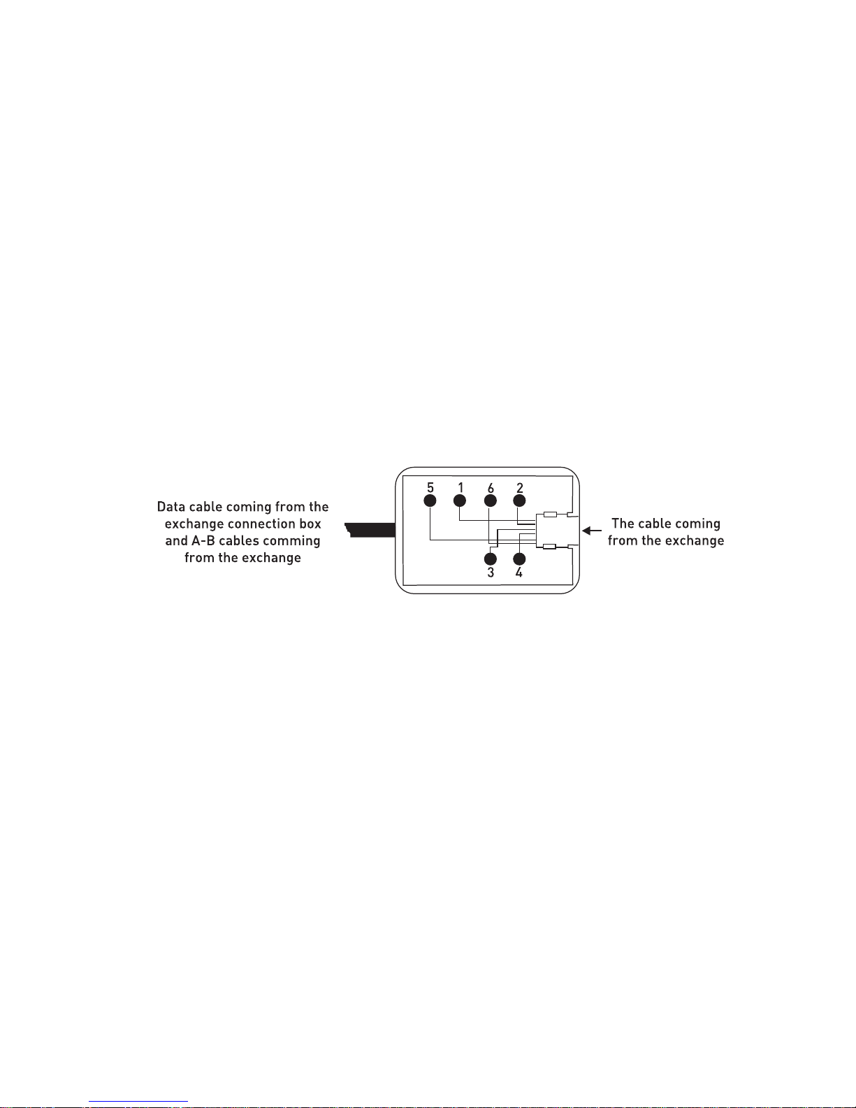
In addition to the telephone data cable, another cable that can be used during
installation is the “system data cable”, which is distributed as one for each exchange.
One end of the “system data cable” has been attached to its connection box. On the
other, there is a connector at the free end of the cable, which is fit for the KTS (serial
data) port socket of the corresponding exchange.
The 6-pin, RJ-type male connector on the other side of the connection box will be
employed for parallel connection of data / +12 VDC / ground signals.
Page 23

22
Those signals are present on the exchange connection box that is included in the
exchange hardware:
1. + 12 VDC
2. Busy
3. No connection
4. No connection
5. Ground (GND)
6. Data signal
NOTE: The “Busy” signal is used for KY16 Mini Printer, which is another KAREL
product.
If the distance between the exchange and FT10 is more than the total lengths of the
two cables mentioned above (approximately 4 meters), then it would be necessary to
obtain flat telephone cable in order to make the connection between the two connection
boxes. Note that the cable should comply with the standards.
Connecting FT10 To The Exchange:
Cabling of the first telephone to be connected to the KTS line of the
exchange:
1) Free end of the “system data cable” is attached to the KTS port socket of the system.
2) One end of the “telephone data cable” is attached to the connecti on bo x that is at the
end of the system data cable. The other end is connected to the FT 10 telephone.
3) Connection of the A-B wires of the corresponding extension is made to the
connection box. In order to do that, two wires taken from the corresp onding extension
connector of the exchange are attached to the red and green points on the connection
box.
NOTE1: If the exchange is MS26C, MS38S or MS224, and if the first FT10 will be
connected to the operator, then connections of the extension wires should not be
made, because the A and B connections for the operator are also ready on the KTS
sockets of those exchanges. Additional realization of those connections may prevent
the exchange from operating.
Page 24

23
NOTE2: If the exchange and the first telephone are far away from each other for more
than 4 meters, then standard flat telephone elongation cable of sufficient le ngth should
be applied in order to provide the connection between the two connection boxes.
4) After the telephone has been connected, the extension settings should be done, as
will be explained in the next section.
Cabling of the telephone while there is another device connected to the
KTS line of the exchange:
1) Parallel connection should be made from the connection box of the device that has
previously been connected to the KTS line to the wires that carry data (white), +12 VDC
(blue) and ground (black) signals and this connection should be made in the same
order to the connection box of the FT10 that is newly to be connected to the exchange.
NOTE: Short circuit or wrong order of the wires during the installation may result in
improper operation or malfunction of the exchange or the other devices that have been
connected to the KTS line.
2) Then, extension connection to FT10 should be made. In order to do that, two wires
taken from the corresponding extension connector of the exchange should be attache d
to the red and green points on the connection box of FT10.
3) After the telephone has been connected, the extension settings should be done, as
will be explained in the next section.
IMPORTANT NOTE: If FT10 is to be connected over a distance lo nger than 5 meters,
then A-B (ring-tip) and serial data (KTS) wires should be carried over separate cabl es,
one should especially pay attention to employ shielded cables for long-distance
installations of serial data wires.
The figures below illustrate connections of FT10 to the MS26C, MS38S and MS224
exchanges, respectively, and connections to the MS48S, MS48, MS48C and MS128
exchanges, respectively.
Page 25

24
Page 26

25
Defining Extension Number For FT10
At the first moment FT10 is connected to the exchange, the two-digit extension number
is displayed in the “Terminal no=aa” format. That number has been set as “11” as
factory default and it signifies the last two digits of the extension number.
If the data on the LCD display are changing upon l ifting and replacing the handset, then
that indicates extension settings are correct. However, if those data are not changing,
then the extension number of FT10 must be set. In order to do that:
1) The “Park” key is pressed until the message “Terminal no=aa” appears on the
display (aa= a two-digit number – last two digits of the physical number of the
extension.)
2) One proceeds by pressing the “Park” key in short whiles until the extensi on number
that is desired to be set appears on the LCD display.
3) When the desired number has appeared on the display, the handset is lifted and
replaced once. From then on, FT10 will operate at that defined extension.
NOTE: When number of another extension of the exchange is entered to FT10, the
speech channel is activated; however, the data line does not function.
Number Of FT10s That Can Be Connected To The Exchange
And Connection Distances
1) The FT10 telephones can be connected to the first 16 extensions of the exchange.
2) Number of FT10s that will be connected to the exchange and accessories using the
external data line of the exchange should not exceed 8 in total. The maximum number
of FT10 which will be connected to the system can be 8.
3) If “data / 12 VDC / ground” signals and the “A / B” wires are carried to FT10 over
separate cables, then an FT10 can be located at most 250 meters far from the
exchange in the event that ordinary cables are employed.
That distance would decrease as the number of feature telephone sets that are
connected to the exchange increase. For example, when 8 FT10s are connected to the
exchange as previously explained, the maximum allowed distance between the
telephone sets and the exchange drops to 25 meters.
In such a case, if the “12 VDC” signal amplitude of the last FT10 drops below +8.5
VDC, then the performance may be improved by connecting a +12 VDC po wer supply
between 12VDC and ground terminals.
Page 27

26
FT10 Start-up State
The telephone set would be ready for operation after the required connections have
been made and the correct extension number has been defi ned. The display and the
programmable keys start to perform their functions.
Beginning LED simulation will light just in yellow for the F T20 feature phones.
By default, there is no program assignment for the programmable keys. These keys are
to be programmed by user according to needs. Please refer to the section “Key
Settings and Automatic Settings” in this guide for detailed information. In order to
change settings of your telephone and other settings of your exchange, refer to the
section “Phone Settings”. Settings of telephone set are not cleared as the exchange is
shut down and then powered.
If the telephone set has previously been connected to the s ystem and if it is connected
again after having been removed, then it gets ready for use within a few seconds. In
that short period, first the version information of FT10, then the “Terminal No:aa”
message appear on the display. After that message the telephone would be ready for
utilization.
In the event that the exchange is reset or is shut down and restarted while the
telephone has been connected to the exchange, the telepho ne first waits for the system
to start and display the version information of FT10 and then the message “Terminal
No: aa" (for 15 sec.), then it establishes the connection with the exchange after that
waiting period.
Page 28

27
FT20 INSTALLATION
In order to operate the telephone, first, the spiral handset cable is connected to the
connection point under the telephone and to the handset. Then FT20 must be
connected to the KTS line of the exchange.
Required Hardware For The Connection:
FT20 is presented to the user together with a “telephone data cable” of length 2.5 m.
and a connection box. There are 6-pin, RJ-type male connectors at both ends of the
“telephone data cable”. One end of this cable has been attached to a 6-pin, RJ-type
female connector that is on the connection box. The connector at the other end of the
cable will be attached to its correspondent under FT20. The cavity, which is on the side
of the connection box without the 6-pin, RJ-type female connector, has been left for
other cabling that would be carried out on the box. (Parallel connection of the -48VDC /
/ GROUND (GND) + DATA signals and A / B terminal connections.)
Those signals are present on the console connection box that is
included in the FT20 hardware:
1- - 48VDC
2- No connection
3- B (Tip) signal coming from
the corresponding extension
4- A (Ring) signal coming from
the corresponding extension
5- Ground (GND) + Data
6- No connection
In addition to the telephone data cable, another cable that can be used during
installation is the “system data cable”, which is distributed as one for each exchange.
One end of the “system data cable” has been attached to its connection box. On the
other, there is a connector at the free end of the cable, which is fit for the KTS (serial
data) port socket of the corresponding exchange.
The 6-pin, RJ-type male connector on the other side of the connection box will be
employed for parallel connection of -48 VDC / ground + data signals.
Page 29

28
Those signals are present on the exchange connection box that is
included in the exchange hardware:
1- - 48 VDC
2- No Connection
3- No connection
4- No connection
5- Ground (GND) + data
6- No connection
If the distance between the exchange and FT20 is more than the total lengths of the
two cables mentioned above (approximately 4 meters), then it would be necessary to
obtain flat telephone cable in order to make the connection between the two connection
boxes. Note that the cable should comply with the standards.
Connecting FT20 To The Exchange:
Cabling of the first telephone to be connected to the KTS line of the
exchange:
1) Free end of the “system data cable” is attached to the KTS port socket of the system.
2) One end of the “telephone data cable” is attached to the connecti on bo x that is at the
end of the system data cable. The other end is connected to the FT 20 telephone.
3) Connection of the A-B wires of the corresponding extension is made to the
connection box. In order to do that, two wires taken from the corresp onding extension
connector of the exchange are attached to the red and green points on the connection
box.
NOTE: If the exchange and the first telephone are far away from each other for more
than 4 meters, then standard flat telephone elongation cable of sufficient le ngth should
be applied in order to provide the connection bet ween the two connection boxes.
4) After the telephone has been connected, the extension settings should be done, as
will be explained in the next section.
Page 30

29
Cabling of the telephone while there is another device connected to the
KTS line of the exchange:
1) Parallel connection should be made from the connection box of the device that has
previously been connected to the KTS line to the wires that carry ground and data
(blue) and -48 VDC (black) signals and this connection should be made in the same
order to the connection box of the FT20 that is newly to be connected to the exchange.
NOTE: Short circuit or wrong order of the wires during the installation may result in
improper operation or malfunction of the exchange or the other devices that have been
connected to the KTS line.
2) Then, extension connection to FT20 should be made. In order to do that, two wires
taken from the corresponding extension connector of the exchange should be attache d
to the red and green points on the connection box of FT20.
3) After the telephone has been connected, the extension settings should be done, as
will be explained in the next section.
IMPORTANT NOTE: If FT20 is to be connected over a distance lo nger than 5 meters,
then A-B (ring-tip) and serial data (KTS) wires should be carried over separate cabl es,
one should especially pay attention to employ shielded cables for long-distance
installations of serial data wires.
The illustration below shows the connection of FT20 to the exchange.
WARNING!
Check if there is any short circuit among connections.
Page 31

30
Defining Extension Number For FT20
At the first moment FT20 is connected to the exchange, the four-digit extension number
appears on the display in the “Telephone no=aaaa” format.
If the data on the LCD display are changing upon l ifting and re plac ing the han ds et, then
that indicates extension settings are correct. However, if those data are not changin g,
then the extension number of FT20 must be set. In order to do that:
1) The message “Telephone number / no= ” appears o n the display after the “Park”
key is pressed for a long time and then released.
2) The telephone number is entered according to the numerical values that have
been assigned to the programmable keys. (Those numerical values have been
given in detail in the section “FT20 Start-Up State”.)
3) After the telephone number, which has been entered accordingly is confirmed
through the “Connect” key, FT20 will operate at that defined extension.
NOTE: When number of another extension of the exchange is entered to FT20, the
speech channel is activated; however, the data line do es not function in parallel to the
speech path.
Number Of FT20s That Can Be Connected To The Exchange
And Connection Distances:
1) The FT20 telephones can be connected to any extension of the exchange.
2) Number of FT20s that will be connected to the exchange and accessories using
the external data line of the exchange should not exceed 25 in total.
3) If “-48VDC/ ground+ data” signals and the “A / B” wires are carried to FT20 over
separate cables, then an FT20 can be located at most 2 kms. far from the
exchange in the event that ordinary cables are employed.
That distance would decrease as the number of the featur e telephone s ets that are
connected to the exchange increase. For example, when 10 FT20s are conne cted
to the exchange as previously explained, the ma ximum allowed distance between
the telephone sets and the exchange drops to 250 meters.
FT20 Start-Up State
When the telephone set is attached to the system for the first time, user is prompted to
enter her/his extension number through the message “Telepho ne Number/No= ” on the
display. At that time, the display cursor enables data entry. After the user has entered
her/his telephone number by making use of the programmable keys of the elephone set
and has confirmed it through the “Connect” key, the telephone would get in use
following three short beeps. In case the entered number is not a proper one for the
exchange, the message “Enter a valid number” is displa yed and short beep is emitted.
This case would continue until the correct number is entered.
Page 32

31
In the table above, numerical values of the programmable keys , which will be used for
entering the extension number that belongs to FT20 and which are valid only for this
case.
Example: If the number of the FT 20 feature telephone set, which is determined by the
exchange is 1023, then the number 1023 is suppos ed be entered upon the message
“Telephone Number/ no=” that will appear on the display when the telephone is
attached to the system for the first time. As can be seen in the Table-1 as well, the
telephone number is typed by pressing each of the 1
st
key (numeral 1), the 10th key
(numeral 0), the 2
nd
key (numeral 2) and the 3rd key (numeral 3) once and the number
will have been assigned to the telephone after the confirmation through the “Connect”
key.
NOTE: When number of another extension of the exchange is entered to FT20, the
data line is activated; however, it does not function in parallel to the speech channels.
If the telephone set has previously been connected to the s ystem and if it is connected
again after having been removed, then it gets ready for use automatically within 30
seconds. In that 30-second period, first the version information of FT20 appears on the
display, then the “Connecting/No:aaaa” message. After that message the telephone
would be ready for utilization. The entire LEDs of FT20 are turned on and off once for
testing during the start-up period. If the extension number that has previously been
defined for FT20 does not exist in the system, then the message “Enter correct
number” appears on the display and the user is expected to enter the extension
number again. In case the user fails to enter a new extension number, the message
“Connecting/No:aaaa” is displayed once every minute u pon each attempt to connect to
the exchange. If the connection fails each time, then error tone is received together
with the incorrect number message. The user is kept on being prompted for a correct
extension number each time. That process is repeated until the FT 20 user enters the
correct extension number. (Extension number entry is supposed to be done as
explained above.) In the event that the exchange is reset or is shut down and restarted
while the telephone has been connected to the exchange, the tel ephone first waits for
the system to start and display the version information of FT20 and then the message
“Connecting/No:aaaa”, while the system detects the entire installed cards (for 15 sec.),
then it establishes the connection with the exchange after that waiting period.
Page 33

32
UTILIZATION FEATURES
DEFAULTS AND ACTIVE SERVICE
INFORMATION
The display is the most active conductor for the usage of the FT telephones. The
telephone is easily utilized by viewing through the display the active features of the
telephone and the exchange, information about incoming calls, options that could be
applied during a call, data coming over the network and t he options for Phone Settings.
Hence, utilization features of the telephone will be e xplained from the beginning b y the
LCD display views.
1. While Telephone Is On Hook:
On the LCD display, time, date and services that have been activated at that moment, if
there are any, or system services that are active are visualized while the telepho ne is
on hook.
SAMPLE DISPLAY WHILE THE TELEPHONE IS ON HOOK
SAMPLE DISPLAY WHILE THE TELEPHONE IS ON HOOK AND THE ACTIVE
SERVICE IS PRESENT
1.1. The display order of the services that are active has been arranged so as the
most recent active service would be displayed first.
1.2. While telephone is on hook and there are messages on the display related to the
services that are active, a user can perform operations related to those services
with ease. For instance, s/he can view the contents of Missed Calls through the
“Details” key. In that mode of the telephone, the Missed Call information is
displayed in the middle line of the screen as sourc e of the call (line or extension),
access code of the source, hour and minute of the call, respectively. Moreover,
date and time information is displayed in the top line of the screen an d operations
that could be done on Missed Calls at the bottom line. If the numbers in the
Missed Call list have been saved in the phone book, then saved names in the
phone book, instead of numbers, are displayed.
Page 34

33
2. While Telephone Is Off Hook:
When the telephone goes off hook and dial tone is received, screen clock is situated at
the top of the display and the message related to the active services at the bottom.
While there is a message related to active services, operation quer y that could be done
corresponding to that message is located at the bottom of the display.
(Operation queries that could be done for active services of the system are displayed
when the user is the system supervisor.) As soon as any number is started to be dialed,
while the clock is displayed at the top of the screen, the number s being entered slide
from right to left at the bottom.
2.1 Operation queries corresponding to the service that is active:
For the activated services: Cancel?
These services are Follow Me [(FT10) xxx, (FT20) xxxx], Telephone Lock, Auto-dial,
Music (FT10), Do Not Disturb and Alarm.
NOTE:
• x: Extension number to which forwarding is done
FT10 SCREEN THAT APPEARS WHEN THE TELEPHONE IS FORWARDED TO THE
EXTENSION WITH NUMBER 112
FT20 SCREEN THAT APPEARS WHEN THE TELEPHONE IS FORWARDED TO THE
EXTENSION WITH NUMBER 1023
NOTE:
If the number of the extension to which the telephone is forwarded is present in the
phone book, then the name of the extension, instead of the number, is displaye d.
FT20 Do Not Disturb mode has been activated. It can be deactivated through the
“Cancel” key.
Page 35

34
For The Services In Which The Operator Can Intervene: Night Mode
By this feature that is employed by the operator only, you can put the paramet ers on
line, which you would like to be applied by the system while operating at night. For
instance, actions such as employing the Auto Attendant to answer line calls, disabling
the entire extensions, except the operator, to access lines.
For the Missed Calls: Details?
A list of the Missed Calls is displayed including source and time of the call
(extension/line number). Information of Missed Calls, starting from the most recent one
is saved in the list, 8 ones for FT10 and 20 ones for FT20. (If there are Missed Calls
that have not yet been checked by the user, then that information is displayed on the
screen.)
IN THE EVENT THAT TELEPHONE IS ON AND OFF HOOK
VIEW OF THE DISPLAY AFTER THE “DETAILS” KEY HAS BEEN PRESSED
NOTE:
In case any information of a call or an activated service, which is related to the
telephone is received while the Missed Calls are being viewed on the display, the
Missed Call being viewed is considered as not checked and it is not cleared from the
Missed Call list. Hence, the user has the opportunit y to view that call he has missed,
when he would like to view the Missed Calls again.
Page 36

35
While telephone is locked: Unlock?
IF THE TELEPHONE HAS BEEN LOCKED BY 837 PPP(P), THEN IT CAN BE
UNLOCKED THROUGH THE “UNLOCK” KEY.
NOTE:
PPP(P): The password for FT10 is of 3 digits, whereas the one for FT20 is of 4 digits.
HERE THE LOCK CAN BE CANCELLED BY ENTERING PASSWORD.
THE VIEW BELOW APPEARS AFTER THE UNLOCK KEY.
While there is a parked line: Retrieve?
2.2 When any call request is received by the telephone, the notification indicating
the call request blinks in the second line from the top of the display, whereas
source (extension + her/his number, external line + its number, external line
retrieved + its number) of the call is displayed in the second line from the bottom.
For Call Back Call, Auto-dial and Alarm, the user is notified only by a message
blinking on the display in the second line from the top. At this view, time and date
information is still displayed at the top of the screen.
VIEW OF THE DISPLAY WHEN A CALL REQUEST IS RECEIVED:
Page 37

36
VIEW, WHICH SIGNIFIES THAT AUTOMATIC CALL HAS BEEN ACCOMPLISHED:
VIEW, WHICH SHOWS THE LINE THAT IS SELECTED BY AUTO-DILAER HAS
BEEN CALLED
NOTE:
• (Line number is displayed as DD and extension number as AAA for FT10.)
• (Line number is displayed as D DDD and extension number as AAAA for FT20.)
Page 38

37
CONVERSATION FEATURES:
1. When The User Accesses A Line
While the line is being displayed on FT10 with its number, the user is inquired for “Park”
and “Hold” options. On FT20, on the other hand, the user is inquired for “Drop” option
while the line is being displayed with its number. In this mode, line number that is dialed
is displayed in the second line from the top on the screen.
[FT20] If the user fails to dial a number within 4 seconds after s/he accesses the line,
then messages on the display switches to “Hold?” and “Call Back?”. In this state,
numbers dialed by the user are not displayed, but they are detected.
NOTE: On conversation with the line, the dialed line n umber is continuously displayed
on the screen.
2. In The Event That A Line Is Transferred To The User or The
User Picks Up A Line Call Coming To Someone Else
The message “Hold?”, together with the line number that has been pick ed up is brought
to view.
When the transferred call rings on the FT 20 phone the nam e-number information of the
extension who transfers the call will be displaye d on screen. This facility is supported
with the DS system software version of Z_ADA and better. Moreover, the name and
number informations need to be defined on IDEA program and the phonebook of FT20.
Page 39

38
3. In The Event That The User Calls Any Extension
One of the messages called number is ringing, forwarded number is ringing or
telephone in the group is ringing is dis playe d together with the number of the e xtension
that is ringing. In this state, actions that could be taken by the user, as well as the
corresponding queries such as “Call Back” and “Message” will be l ocated at the bottom
line of the display and upon pressing the right selection key, the operation will be
accomplished.
NOTE:
• If the extension number has already been saved in the phone book, then the
stored name, instead of the number, is displayed.
4. In The Event That The User Calls A Busy Extension Or
Attempts To Access A Busy Line
4.1. Busy extension: The busy status is brought to view, together with the extension
number and the user is inquired for the “Call Back” and “Message” options.
4.2. Busy line: The busy status is brought to view, together with the line number and
the user is inquired for the “Call Back” option.
4.3. Extension-Extension, Extension-Line: If the called extension is conversing with
another line or extension, then number of the extension is displayed, as well as the
notification of that conversation and number of the extension or the li ne with which that
extension is conversing and then the user is inq uired for the “Call Back” and “Message”
options. Moreover, the message “Conversing” is displayed in the seco nd line from the
top on FT10 screen, if the called extension is conversing with a line.
Page 40

39
4.4. Line-Extension, Line-Line: Number of the line which is attempted to be
accessed, as well as notification of the busy status and the number through which the
line is accessed is brought to view and then the user is inquired for the “Call Back”
option.
5. While The User Is Making Conversation With Any Extension
Number of the extension with whom the conversation is going on is dis played. In this
state, the user is inquired for the “Hold?” option.
6. When The User Has Put An Extension/Line On Hold
The user is inquired for the “Retrieve?” option, together with the number of the
extension/line on hold.
7. While There Is An Extension/Line On Hold:
In case the user calls a busy extension, the busy status is displayed as well as the
extension number (If there is an extension or line, with which the busy extension is
conversing, then that number is displayed, too.) and the user is inquired for “Retrieve?
+ extension/line number on hold” and “Transfer? + extension/line number on hold”
options. Moreover, if there is more than one call on hold on FT20 phon e in the case the
extension is busy, the number of the calls in queue are displayed. This facility is
supported with the DS system software version of Z_ABH or better.
Page 41

40
EXAMPLE: THE SCREEN VIEW DISPLAYING THAT THE CALLED EXTENSION
WITH NUMBER 1029 IS BUSY WHILE THE EXTENSION WITH NUMBER 1023 IS ON
HOLD.
8. In The Event That The User Calls An Extension While There Is
A Line On Hold
The status of the user is brought to view by one of the corresponding messages and
the user is inquired for “Retrieve? + line number on hold” and “T ransfer? + line number
on hold” options.
9. In The Event That The User Makes An Internal Conversation
While There Is An Extension/Line On Hold
While the conversation status is brought to view, as well as the number with which the
conversation is being made, the user is inquired for the “Hold?” and “Call Back?”
options.
NOTE:
• As one proceeds by the nav igation keys, “Park” and “Auto-dial” menus will appear.
10. Other Messages:
In case the user takes an erroneous action during a conversation, the
notification *Error* begins to blink in the second line of the screen and date and time
information is displayed at the top of the screen. In addition to that, the message
“Clear” appears at the lower left corner. One can go back to the Ready by the “Clear”
option.
Page 42

41
SCREEN VIEW SIGNIFYING THAT A CALL IS MADE THROUGH MEMORY:
* This message disappears after having been displ ayed for a while.
SCREEN VIEW SHOWING QUANTITY OF PULSE PRICES IN CASE OF A
CONVERSATION WITH A LINE:
SCREEN VIEW SHOWING THAT THE EXTENSION WITH NUMBER AAA IS
BEING WARNED THROUGH EAR:
THE MESSAGE THAT APPEARS WHEN THE SYSTEM CAPACITY IS
INQUIRED BY THE CODE 739:
THE MESSAGE WHICH APPEARS WHEN THE TRANSFERRED CALL TURNS
BACK:
Note: When there is a returning parked call and the telephone is ringing, the cal ler ID is
displayed together with the access code of line.
Page 43

42
PROGRAM FEATURES
PROGRAMMING MENUS
The user performs entrance to programming by making use of the flexibly functional
selection key that is under the option “menu” that appears on the dis play or specially
functional MENU key, while the telephone is off hook and di al tone is being receive d. In
order for the user to activate the services s/he makes use of or deactivate the active
ones within the program menus, a single menu comes to view. If the service, which the
user would like to do operations on, is active, then the “Disable” menu, or else the
“Enable” menu come to view. The programming features consist of 6 main menus and
their submenus.
Characteristics of the entire menus have been explained below.
Page 44

43
CALL OPTIONS
Submenu titles:
• Call Diversion
o All Calls/ Extension No=
o No Answer/ Extension No=
o No Answer Cancel
• Auto Dial
o Last Number
o Private Pool/ Register No=
o Common Pool/ Register No=
• Paging
o All
o Group/ Extension No=
o Extension/ Extension No=
• Missed Calls
• Answered
• Dialled
Call Diversion
- When All Calls is selected and an extension number is entered within 30 seconds,
all calls coming to the FT user rings at the extension specified here.
- When No Answer is selected and an extension number is entered within 30
seconds, an incoming call is forwarded to the extension specified here, if it is still
not answered although it has rung three times.
- No Answer Cancel option can be selected to cancel the previously activated
Follow Me No answer feature.
Auto Dial
The telephone automatically calls the corresponding number when the auto-dialer is
activated. If the called party is busy, then the calling action is performed repeate dly in
every 15 seconds. As soon as the busyness of the opp osite part y is over, the teleph one
notifies that by ringing itself or by short beep. This feature can be deactiv ated by using
the “Cancel” option on the display.
- By selecting the Last Nu mber option, the most recent number that has been dialed
is automatically called.
- When the Private Pool option is activated, the private pool numbers, which hav e
previously been entered into the memory by the menu “Private Pool Entry”, are
automatically called. The value to be entered here is one of the two-digit private
pool indices in the range 01-20 for FT10 and single-digit ind ices in the range 1-9 for
FT20.
- By the Common Pool option, the common pool numbers, who have been stored in
the exchange and whose entries have been done by the operator only are
automatically called.
Page 45

44
Paging
In connection with the handsfree feature, pagings in several forms could be done in
order to be heard through the speakers of the telephones while dial tone is being
received.
- All
- Group
- Private
Missed Calls
Information about the most recent 8 Missed Calls for FT10 and 20 most recent Missed
Calls for FT20 can be successively viewed including source and time of the call. In the
event that there are more than one Missed Calls, they can be browsed by using the
navigation keys on the display. In case the source of the unanswered all is an
extension, if name of the extension is present in the phone book, then that name is
displayed instead of the number. The “Call” option in that menu does not provide for
direct calling of the number.
- No record!
- List of Missed Calls
Answered (FT20)
Information about the most recent 20 Answered Calls can be successively viewed
including source and time of the call. In the event that there are more than one
Answered Call, they can be browsed by using the navigation keys on the display. In
case the source of the Answered call is an extension, if name of the extension is
present in the phone book, then that name is displayed instead of the number. The
“Call” option in that menu provides for direct calling of the number.
Dialed (FT20)
Information about the most recent 20 Dialed Calls can be successively viewed including
source and time of the call. In the event that there are more than one Dialed Call, they
can be browsed by using the navigation keys o n the display. In case the source of the
Dialed call is an extension, if name of the extensi on is present in the phone book, then
that name is displayed instead of the number. The “Call” option in that menu provides
for direct calling of the number.
Page 46

45
PHONE SETTINGS
Submenu titles:
• Key Settings
o Extension
• Press Key/ Extension No=
o Line
• Press Key/ Line No=
o Private Pool
• Press Key/ Register No=/ No=
o Common Pool
• Press Key/ Register No=
o Feature
• Press Key
o Follow Me
o Call Back Key
o Do Not Disturb Key
o Phone Lock Key
o Conference Key
o Night Mode Key
o Auto Dial Key (FT10)
o Message Listen Key
o Page Key
o Call Pick Up Key (FT20)
o Feature Code (FT20)
• Press Key/ No=
o Auto Setting
• Option1
• Option2
• Option3
• Option4 (FT10)
• Clear All?
• Do Not Disturb
o Enable/ Disable
• Reminder
o Without Message/ Time=
o With Message/ Time= / Please Leave Message
• Eprom Version
o System Version
FT Version
• Lazy Mode
o Enable/ Disable
• Private Pool Entry (FT20)
o Register No=/ No=
• Language
• Headphone
o Disable
Page 47

46
o With Handsfree
o Without Handsfree
• Signal Beep Option (FT20)
o Enable/ Disable
• Price
o Last Call
o Meter Pulse Price
• Home Area Code
• Lin e Access Code
Key Settings
Number of keys that can be programmed is 16 in total and assignments of programs
are done to those. In case the user presses those keys conti nuously for one second,
the second function of the key is detected. Therefore, total number of features that can
be programmed becomes 32. During programming, the LED that belongs to the keys
signifies to which key and to which function of the key the assignment is done by
lighting in two colors. When the LED is observed to be lighting in green by pressing the
key until the single short beep is received, the first function will have been assigned
and the second function will have been assigned when the LED is observed to be
lighting in red by pressing the key until the sho rt beep is received for the second time
(for 1 second.) The keys become active after the programming mode is exited
The assignments performed on these keys cannot be cancelle d one by one; however,
new assignments can be done to them without encountering the error signal.
Cancellation of contents of the programmable keys can be carried out by selecting
Phone Settings > Key Settings > Auto Setting> Clear All.
Extension Programming
You can reach an extension you call frequently through a sing le key by programming
her/his number on that key. In order to do that, one first proceeds to the programming
menu.
♦ Press Key: The key, on which the programming will be done, is pressed for a
short or a long period in order to select the first or the second function,
respectively.
♦ Extension no: Then the “Extension No=”menu comes to view. In this menu, the
display cursor enables data entry. After the user enters the extension number by
using the numeric keypad, s/he confirms the extension number s/he has entered
by pressing the “Accept” key. The extension number is of 3 digits for FT10 and of 4
digits for FT20. In case an FT10 user attempts to enter an extension number with
more than 3 digits, the program takes the first three digits as the extension number
and then proceeds to the next menu. An FT20 user can enter an extension num ber
with at most 8 digits, in the event that s/he enters an incorrect number, the
program displays the “Erroneous Number” message.
After the acceptance of the extension number, FT checks whether the extension
number, which is desired to be programmed, has been set to an y key before and if that
extension number has previousl y been programm ed on any key, then the [Previously
Programmed (05)] message is displayed for 1 second and error tone is emitted. If, on
Page 48

47
the other hand, the number has not been programmed before, then FT checks whether
the entered number is a correct one (whether it is defined in the system.)
In the event that the entered number on FT10 is not correct (defined in the system) the
“Erroneous Number” message is displayed for 1 second and error tone is received.
In case a number that has not been defined in the system is entered for FT20, the
message “Enter correct number” is displayed. On the other hand, in the event that the
number is correct, the message “Successful” is displayed for 1 second, OK tone is
received and the Key Settings is completed in both systems.
An extension number can be assigned to a single key only. After the programming
mode is exited and those keys are pressed, the extension that has been stored on the
key is directly called. In addition to the calling function, status of the extension, which
has been programmed as the first function of the programmable keys can be vie wed by
the LED next to it, as described below.
Extension Status Red LED
On Hook Off
Busy Continuously On
Ringing Blinking
[FT10] Calling the
Operator
Blinking fast
NOTE: LEDs light in reverse colour based on the “pag e ke y”. LED of the extension who
is in the conversation with the FT user or LED of the parked extension/line lights in the
direct contrary colour to the “page” key. For exampl e, while the page key is lighting in
red colour, one of the exact extension LED, who is in the conversation with this FT
user, will light in green. If the page key lights in green, in this case the LED of this
extension will light in red. This facility is only valid for FT20 telephone sets.
Line Programming
It enables you to program a specific line number on a key. By pressing that key, you
can access the line that has been programmed on the ke y and make a call (provided
that it is vacant) and you can access that number by a single key. In order to do that,
one proceeds to the extension programming menu.
♦ Press Key: The key, on which the programming will be done, is pressed for a
short or a long period in order to select the first or the second function,
respectively.
♦ Line no: If a determined line number is entered and confirmed, then that line
number will have been assigned to that key.
Programming one of the line access codes such as 01,02… for FT10 is sufficient for
accessing the line directly when the programmed key is presse d. The programme d key
detects the number as 701,702… and provides making calls b y accessing the lin e. If an
incorrect code is entered, on the other hand, the user is warned by the message
“Erroneous Number”.
For FT20, on the other hand, it is necessary to enter the line access codes that are
present in the system 701,702, 703…. That code could be of at most 8 digits. In case a
Page 49

48
line that has not been defined in the system is entered, the message “Enter correct
number” is displayed.
A line access code can be assigned to a single key only.
After the programming mode has been exited, upon pressing those keys, it is possi ble
to access the programmed line, without pressing 9. While a line that has been assigned
to a programmable key has already been accessed, if that key is pressed, the n the line
is parked. The line is retrieved upon pressing the key again.
WARNING
[FT20]Under the “Line” submenu, the access codes of ISDN (BRI/PRI) can not be
accepted.
[FT20] If the external line is called, this external line number will be displayed on the
screen continuously.
Status of the line, which has been programmed as the first function of the key can be
viewed by the LED next to it, as described below.
Line Status Red LED
Vacant Off
Busy Continuously On
Call request is being received Blinking
Parked Blinking fast
[FT20] Out of Service
Off
Private Pool Programming
You can program 20 line numbers for FT10 and 9 line n umbers for F T20, which you call
most frequently on the private pool of your telephone. You could shorten duration of
calling action by programming the memory numbers on the keys. However, that
programming is carried out for FT20 depending on the m emory storage that has been
done previously through the PHONE SETTINGS >PRIVATE POOL menu. On the other
hand, it can be used for FT10 for two kinds of pro gramming. The first of them is a kind
of memory storage, in which 01-20 entries can be stored and determined numbers are
entered by the “no=” option. In the second of them, the entire programming codes out
of the service options that have been specified in the user’s guide ca n be assigned to
the programmable keys by entering the Feature codes.
FT10
♦ Press Key: The key, on which the programming will be done, is pressed for a
short or a long period in order to select the first or the second function,
respectively.
♦ Register no: Afterwards, the “Register no=” menu is displayed. In this menu, the
display cursor enables data entry. As soon as the user enters the second d igit of
the number s/he has started to enter (01-20), FT10 automatically confirms the
number and checks whether the memory number that has already been entered
has previously been assigned to any key (this system is like the one in the
extension programming.)
♦ No: The desired line number or access code is entered. In order to assign the
service codes, on the other hand, first of all one of the codes that are mentioned in
Page 50

49
the user’s guide is dialed after pressing the “*” key and then it is confirm ed. By this
way the service code is assigned to the key.
FT20
♦ Press Key: The key, on which the programming will be done, is pressed for a
short or a long period in order to select the first or the second function,
respectively.
♦ Register no: In this menu, the display cursor enables data entry. Here, entries of
the indices that could be assigned are done as single digit i n the range 1-9. The
entered index is automatically detected and then the num ber that you would lik e to
be assigned to the key is prompted by the “no=” menu.
♦ No: Any desired line number could be entered. Even thoug h 9 is not appended to
the beginning of the numbers that are stored in the private pool, during the calls
made by using the keys, whose assignments are done in this menu, calls are
made by including 9 at the beginning of the numbers in order to access lines
directly. After exiting the programming mode, when these keys are pressed, the
private pool number that has been assigned to the key is directly called.
Common Pool Programming
Line numbers that have been stored in the common pool memory fields with number
00-49 by the operator can easily be assigned to the programmable keys.
♦ Press Key: The key, on which the programming will be done, is pressed for a
short or a long period in order to select the first or the second function,
respectively.
♦ Register no: Indices that belong to the line numbers, which have been entered
into the common pool of the exchange, are assigned to the progr ammable keys by
this menu option. After exiting the programming mode, when these keys are
pressed, the common pool number that has been assigned to the key is directly
called.
[FT20] As a characteristic of the DS200 exchange, the index that is supposed to be
entered here must be exactly of three digits (such as 001.)
Feature
It provides making use of some functions that have been defined in the system by
pressing a single key. For example, in order for the call requests coming to you to ring
at some other extension, you can press the key that has previously been prog rammed
and enter the number of the extension, to which you would like your calls to be
forwarded.
♦ Press Key: The key, on which the programming will be done, is pressed for a
short or a long period in order to select the first or the second function,
respectively.
♦ Then the “Function/ Follow Me Key” menu is displayed. Through the right
navigation key, the desired feature is reached in this menu. After the user has
reached the function s/he wants, confirms it by pressing the “Accept” key. It is
checked whether the selected function has previously been set. If it has been set
Page 51

50
before, then the program is not accepted; it is accepted only if it has not previously
been set and the LED that belongs to that key is turned on. (This system is like the
one in the Extension Programming, the message “Successful” is displayed for 1
second and confirmation tone is received.)
The functions are as follows:
Function Options:
• Follow Me
• Call Back
• Do Not Disturb
• Telephone Lock
• Conference
• Night Mode *
• Auto Dial Key (FT10)
• Message Listen Key
• Page Key
• Call Pick Up Key (FT20)
* It applies only when the user is the operator.
Feature Code [FT20]
Any code of 8 digits can be assigned to the programmable keys by using this menu
option.
♦ Press Key: The key, on which the programming will be done, is pressed for a
short or a long period in order to select the first or the second function,
respectively.
♦ Code: This code may be one, such as 85 (Follow Me) that could be applied by a
user, one, such as 8389 (Wake Up service) that could be applied by the operat or
or one, such as 877777 (Entry to exchange programming) that could be a pplied by
the system supervisor. If the entered number is none of these, then it is detected
as an extension number and that extension is called whenever that ke y is used.
Auto Settings
FT10
There are five different options in order to program the programmable keys
automatically. The keys are automaticall y programmed upon proceeding to the des ired
option and selecting it. These programming options are:
♦ Option 1 (Extension Numbers)
♦ Option 2 (Line Numbers)
♦ Option 3 (Common Pool Numbers)
♦ Option 4 (Automatic Functions)
♦ Clear All
Page 52

51
How the keys will be programmed by each option has been illustrated through
diagrams below. Here, “E” is the abbreviation for extension numbers, “L” for line
numbers and “CP” for the common pool.
Option 1
1.key
Func1 E 111
Func2 E 127
9.key
Func1 E 119
Func2 E 135
2.key
Func1 E 112
Func2 E 128
10.key
Func1 E 120
Func2 E 136
3.key
Func1 E 113
Func2 E 129
11.key
Func1 E 121
Func2 E 137
4.key
Func1 E 114
Func2 E 130
12.key
Func1 E 122
Func2 E 138
5.key
Func1 E 115
Func2 E 131
13.key
Func1 E 123
Func2 E 139
6.key
Func1 E 116
Func2 E 132
14.key
Func1 E 124
Func2 E 140
7.key
Func1 E 117
Fonk2 E 133
15.key
Func1 E 125
Func2 E 141
8.key
Func1 E 118
Func2 E 134
16.key
Func1 E 126
Func2 E 142
Option 2
1.key
Func1 L 1
Func2 L 17
9.key
Func1 L 9
Func2 L 25
2.key
Func1 L 2
Func2 L 18
10.key
Func1 L 10
Func2 L 26
3.key
Func1 L 3
Func2 L 19
11.key
Func1 L 11
Func2 L 27
4.key
Func1 L 4
Func2 L 20
12.key
Func1 L 12
Func2 L 28
5.key
Func1 L 5
Func2 L 21
13.key
Func1 L 13
Func2 E 111
6.key
Func1 L 6
Func2 L 22
14.key
Func1 L 14
Func2 E 112
7.key
Func1 L 7
Func2 L 23
15.key
Func1 L 15
Func2 E 113
8.key
Func1 L 8
Func2 L 24
16.key
Func1 L 16
Func2 E 114
Page 53

52
Option 3
1.key
Func1 CP 00
Func2 CP 16
9.key
Func1 CP 08
Func2 CP 24
2.key
Func1 CP 01
Func2 CP 17
10.key
Func1 CP 09
Func2 CP 25
3.key
Func1 CP 02
Func2 CP 18
11.key
Func1 CP 10
Func2 CP 26
4.key
Func1 CP 03
Func2 CP 19
12.key
Func1 CP 11
Func2 CP 27
5.key
Func1 CP 04
Func2 CP 20
13.key
Func1 CP 12
Func2 CP 28
6.key
Func1 CP 05
Func2 CP 21
14.key
Func1 CP 13
Func2 CP 29
7.key
Func1 CP 06
Func2 CP 22
15.key
Func1 CP 14
Func2 CP 30
8.key
Func1 CP 07
Func2 CP 23
16.key
Func1 CP 15
Func2 CP 31
Option 4
1.key
Func1 Phone Lock
Func2 Door Opener
9.key
Func1 ACD
Func2 E 115
2.key
Func1 Message Listen
Func2 Door Phone
10.key
Func1 Mute
Func2 E 116
3.key
Func1 Auto-Dial
Func2 Hookflash
11.key
Func1 Night Mode
Func2 E 117
4.key
Func1 Reminder
Func2 Lazy Mode
12.key
Func1 Music
Func2 E 118
5.key
Func1 Do Not Disturb
Func2 E 111
13.key
Func1 Call Pick Up
Func2 E 119
6.key
Func1 Follow Me
Func2 E 112
14.key
Func1 Conference
Func2 E 120
7.key
Func1 Line Park
Func2 E 113
15.key
Func1 Call Back
Func2 E 121
8.key
Func1 Parallel Operator
Func2 E 114
16.key
Func1 Paging
Func2 E 122
FT20
When selected, 3 different options are presented to the user. Upon any of those
options is selected, extension, line or user features ar e assigned to the programmable
keys automatically or the entire key assignments that have previously been done are
cleared. As for these options:
♦ Option 1 (Extension Numbers)
♦ Option 2 (Line Numbers)
♦ Option 3 (Automatic Functions)
♦ Clear All
Page 54

53
The assignments done to the programmable keys automaticall y when this menu item is
selected have been illustrated through diagrams below.
Here, “E” is the abbreviation for extension numbers, “L” for line numbers, “PP”
for the private pool and “CP” for the common pool.
Option 1
1.key
Func1 E 1110
Func2 E 1126
9.key
Func1 E 1118
Func2 E 1134
2.key
Func1 E 1111
Func2 E 1127
10.key
Func1 E 1119
Func2 E 1135
3.key
Func1 E 1112
Func2 E 1128
11.key
Func1 E 1120
Func2 E 1136
4.key
Func1 E 1113
Func2 E 1129
12.key
Func1 E 1121
Func2 E 1137
5.key
Func1 E 1114
Func2 E 1130
13.key
Func1 E 1122
Func2 E 1138
6.key
Func1 E 1115
Func2 E 1131
14.key
Func1 E 1123
Func2 E 1139
7.key
Func1 E 1116
Func2 E 1132
15.key
Func1 E 1124
Func2 E 1140
8.key
Func1 E 1117
Func2 E 1133
16.key
Func1 E 1125
Func2 E 1141
Option 2
1.key
Fonk1 Phone Lock
Fonk2 E 1126
9.key
Fonk1 Lazy Mode
Fonk2 E 1134
2.key
Fonk1 Auto-Dial
Fonk2 E 1127
10.key
Fonk1 Conference
Fonk2 E 1135
3.key
Fonk1 Reminder
Fonk2 E 1128
11.key
Fonk1 Night Mode
Fonk2 E 1136
4.key
Fonk1 Do Not Disturb
Fonk2 E 1129
12.key
Fonk1 E 1121
Fonk2 E 1137
5.key
Fonk1 Follow Me
Fonk2 E 1130
13.key
Fonk1 E 1122
Fonk2 E 1138
6.key
Fonk1 Line Park
Fonk2 E 1131
14.key
Fonk1 E 1123
Fonk2 E 1139
7.key
Fonk1 Call Pick Up
Fonk2 E 1132
15.key
Fonk1 E 1124
Fonk2 E 1140
8.key
Fonk1 Call Back
Fonk2 E 1133
16.key
Fonk1 E 1125
Fonk2 E 1141
Do Not Disturb
♦ When Enable is selected, telephone rings once in every 20 seconds for an
incoming call.
♦ Do Not Disturb mode is cancelled upon selection of Cancel.
Page 55

54
Music (FT10)
♦ By the selection of Activate, music that has been loaded to the exchange can be
listened to. This option can be employed especially for the lines that are put on
hold.
♦ Listening to music option is deactivated by Cancel.
Reminder
♦ With message: Following the entry of the reminder time in “HHMM” format, a
message with maximum duration of 30 seconds could be recorded without waiting
for any notification signal. Whenever the reminder is active, the reminder tone is
received from the telephone. In the meantime, the recorded message can be
listened to repeatedly upon pressing the H/F key. In that case, upon us ing the H/F
key once again, the message and the reminder are cancelled. This option is
displayed only when there is an EVM module installed in the system.
♦ Without message: It provides for receiving of the reminder tone until the
telephone is picked up and then hanged up at the time of reminding, which has
been entered in “HHMM”.
EPROM Version
FT10
By this menu option, one can reach version information of an MS-series exchange and
the FT10 telephone set.
♦ System Version: Example: -MS48 AAA
♦ FT Version: Example: FT10/4 ABE
FT20
One can reach version information of the DS200 exchange and the FT20 telephone.
♦ System Version: Example: -Z_ADA
♦ FT Version: Example: FT20/4 ABC
Lazy Mode
♦ Enable: When the lazy mode is activated, the telephone is picked up aut omaticall y
in handsfree mode and the call is answered.
♦ By selecting Disable, the lazy mode is exited; hence the telephone is not
automatically picked when a call is received.
In order to reach the “Disable” and “Put on line” options, the “Sele ct” option may have
to be employed twice.
Page 56

55
Private Pool Entry (FT20)
♦ Register no: The private pool index in the range 1-9 is entered correspond ing to
the “Register no” message displayed when this menu item is selected.
♦ No: Then, line number that will be assigned to the specified index is entered. No
code should be appended to the beginning of that number for accessing a line.
The STD, the ISD, or the GSM operator codes should be fully enter ed, including 0.
Extension numbers may not be assigned as private pool numbers.
Language
Any desired one out of the language options that are displayed here, such as Turkish,
English, Spanish, Afrikaans, Polish (FT20), Portuguese (FT10), Russian, French and
Greek can be selected and the telephone starts to display menu messages in the
selected language.
Headphone
The “Headset” option, which is presented in order to make use of the telephone
comfortably by a headset, offers three different options as disable, with handsfree and
without handsfree.
♦ Disable mode is alread y active when the “headset” option is selected for the first
time. It is employed for canceling the different later options.
♦ When With handsfree is selected, the telephone is picked up through the headset
while it is on hook, by the fast handsfree key. Upon pressing it again, the headset
is turned off and the telephone gets into the HF mode.
♦ When Without handsfree is selected, the telephone is not picked up through the
headset while it is on hook, by the fast handsfree key. If the handset is lifted d uring
a conversation via the headset, the voice level decreases, for it will be split into
two.
Signal Beep Option
♦ When the Enable option is selected, a special warning tone is received for an
incoming call, in case the phone is busy.
♦ The warning tone is cancelled through the Disable option.
In order to reach the “Enable” and “Disable” options, the “Accept” or “Select” options
may have to be employed more than once.
Price (FT20)
♦ By the Last Call selection, pricing of the last line, over which the call has been
made is done.
♦
Meter Pulse Price: By selecting “Accept” in this menu, upon entering the pricing
data of maximum five digits, which is considered to correspond to one pulse price,
Page 57

56
the pricing information based on that pulse price information is shown on the
display during conversations. The character “,” is supplied to be entered for
decimal values. For each pulse price the call charging can be calculated as
decimal values. The decimal part can be entered after pressing the character “,”.
Home Area Code (FT20)
With this facility, the city code is entered to the phone memory and the number without
the city code is seen on the called extension phone display when the calling is long
distance or unanswered. (For only FT20-2&4E Feature Pho nes)
When the facility is selected, there is a cursor which supplies maximum 6 digits to be
entered displayed on the screen. With this cursor the desired “home area code” is
entered and then it is confirmed in order to be saved into the memory of the FT20
phone. If any number, within the defined home area code, is dialled only the number
without the area code is displayed on the screen.
The existing area code (AAA) will be shown on the right side of the display when the
“Home Area Code” menu is entered.
Line Access Code:
With this facility, if there is an incoming call that includes the Caller ID information and
the “Area Code”, which has been defined before, only the Line Access Code is
displayed instead of the Area Code on the screen. In order to realize it, firstl y, the line
access code need to be entered to the phone and savied into the mem ory. In this way,
the number information of the call will come with the information of the line access code
not with the area code.
When the facility is selected, there is a cursor which supplies maximum 6 digits to be
entered displayed on the screen. With this cursor the desired “line access code” is
entered and then it is confirmed in order to be saved into the memory of the FT20
phone. If any number, within the defined home area code, is dialled the number with
the line access code is displayed on the screen.
This facility provides to redial the missed calls within the defined codes with a single
key.
The existing line access code (DD) will be shown on the right side of the displa y when
the “Line Access Code” menu is entered.
Example:
For FT20, suppose that “Home Area Code” and “Lin e Access Code“ hav e been defined
successively as “0212” and “9”. If there is an incoming call numbered with “0212
2672030” to the phone, since the first three digits of the inc oming Caller ID information
has been defined before on to the phone, the defined code “0212” will be erased and
the line access code “9” will be added instead of home area code.
Page 58

57
The user will see the number “92672030” through the screen as a call source. When
this calling is got as a missed call by the phone, the user can call this number by
pressing the single “OK” key. The main purpose of this facility is providing to redial such
a missed call within the defined line access code with a single key.
For FT10, if “Home Area Code” has been defined as “0212” and th ere is a call with the
number of “0212 2672030” received, in this case the code “0212” will be er ased from
the head of the number and only the number “2672030” will be displayed on the
screen.
Notes:
- When there is a returning parked call a nd the telephone is ringing, the caller
ID is displayed together with the access code of line.
- When Last Number Redial option is used, only line access code was
displayed on FT20 display. This is modified so that dialled number is also
displayed.
Page 59

58
PHONE SECURITY
Operations of defining / changing passwords, which are re quired in order to make use
of features such as making calls or listening to messages through another extension
within one’s own authorization limits, can be carried out through this upper menu item.
Submenu titles:
• Password
o Define (If there is no password)
o Change (If there is password)
o Cancel
• Phone Lock (If password has been defined)
• Phone Unlock (If telephone is locked)
Password
In case the user has no defined password:
♦ When Define is selected, a password consisting of 3 digits (000…250) for FT10
and 4 digits (0000…8888) for FT20 is expected to be entered.
In case the user has previously entered a password of her/his own:
♦ By the Change option, an existing password can be changed. First of all, the old
password is entered and confirmed, and then the new one is entered. The new
password will be active for later operations.
♦ By the Cancel option, the currently used password is cancelled and operation
requiring a password cannot be done from then on. A pass word must be defined in
order to enable such operations.
Phone Lock
♦ Password: This menu appears only when the telephone is not locked and
becomes active, if a password has been defined before. By this menu option,
password query before line access, as well as telep hone locking, is provided.
Phone Unlock
♦ Password: This menu appears only in the event that the telep hone is locked. The
telephone can be unlocked by using the “Unlock” option and then entering
password.
Page 60

59
MESSAGE
It appears only when there is an installed EVM module (and DRAM module for the twochannel EVM.)
Submenu titles:
• Absent Message
o Read Message
• Message Listen
o All Messages
Message
Password= (If password has been defined)
Absent Message:
♦ Read message: By this menu, you could leave a message to be announced to
people who call you when you are not at your place, provided that you confirm the
message through the “Terminate” key. In case the absent message is employed,
the telephone does not ring when a call is received; instead, the calling party hears
the recorded message. The maximum message duration is 30 seconds.
Message Listen:
You can successively listen to the messages you have received. With the message key
which informs that there is a new message through the related LED which blinks, the
new message can easily be listened to. If a password has been defined, you will be
required to enter it.
♦ All messages: By this menu option, you ca n listen to the e ntire (actually, the ones
whose time-out periods have not yet expired and the ones which have not been
*erased.) messages you have received, provide d that they have not been listened
prior to last 15 minutes or locked.
* The messages, which are listened to by using the “New messages” menu option are
erased in 15 minutes unless they are “locked”.
Page 61

60
SYSTEM SETTINGS
Only the system supervisor is authorized to use this menu. That is, this menu is
displayed only on FTs that are employed as the operator telephone and some special
operations can be carried out via this upper menu option.
Submenu titles:
• Setting Time
o Time=
• Setting Date
o DD/MM/YY=
• Night Mode
o Enable/Disable?
• Common Pool
o Register No=/ No=
• ACD
o Enable/Disable?
• Parallel Operator
o Enable/Disable?
Setting Time
♦ HH:MM=: In this menu, the display cursor enables data entry and the user is
required to enter the system time in 24-hour format. As soon as the user enters the
hour, the character “:” automatically appears on the display and the user is
expected to enter the minute.
Setting Date:
♦ DD/MM/YY=: In this menu, the display cursor enables data entry. As the user
enters the day and the month, the character “/” automatically appears on the
display.
Night Mode:
♦ Enable?: The exchange is taken into the night mode.
♦ Disable?: The exchange is taken out of the night mode.
Common Pool Entry:
♦ In the Register no section, FT10/FT20 primarily prompts the operator for the
common pool number. Then the operator enters it. That number should be of 2
digits in the range 0-99 for FT10 and of 3 digits for FT20 due to the exchange
storage capacity of 1000 records. The number does not need to start with line
access code.
♦ No: It prompts the operator for the number to be stored in the common pool.
Page 62

61
ACD:
♦ Enable?: ACD is put on line.
♦ Disable?: ACD is put off line.
Parallel Operator:
♦ Enable?: Parallel operator is put on line.
♦ Disable?: Parallel operator is put off line.
Page 63

62
PHONE BOOK
A phone book of 60 entries in total can be created by using this upper menu item. 16
characters are reserved for the entry of name/number into the Phone Book. Numbers
that have been stored in the phone book can be searched by us ing the “Find” option
here. Search operation can also be carried out through the “Phone Book” option that
can be seen on the off-hook display of the telephone or by employing the
corresponding function key (phonebook.) Another advantage of using the phone book
is in the event that any information of call, conversation, Missed Call, hold, park or
forwarding that is related to a number stored in the phone book is rec eived, the name
corresponding to that information is displayed. If there are no records that have
previously been stored in the phone, that upper menu item pres ents only two options,
namely, “Add” and “Change”. The option “Change” her e applies only for the permanent
message that will be displayed continuously on th e off-hook display of the telephone.
Once the option “Add” is once employed, additional options ar e also presented to the
user. Note that, while operations related to the entire options are being done, the left
navigation key on the display can be emplo yed for del eting letters or figures.
The numbers which have been added to the Phone Bo ok before can be called through
FT20 phone. Also by pressing the “Phone Book” key which is seen on to the LCD
display the desired number can be dialed afte r the number is found by using the “Find
by number” submenu.
Submenu titles:
• Find
o Find By Name/ Name=
o Find By Number/ No=Time=
• Add
o Name=/ No=
• Change
o Find By Name/ Name=
o Find By Number/ No=
o Constant Message/ Record Message
• Delete
o Find By Name/ Name=
o Find By Number/ No=
o Clear All
Page 64

63
Find
Searches can be performed among the records in the phone book b y using this menu.
Submenus “Find by name” and “Find by number” are located within this me nu.
FT10 users can use this facility to supply an internal or external calling if the MS system
software version is CAA or better.
♦ Find by name: By using this menu, characters are entered and the Find operation
is performed. When the FT telephone set finds the matching name within the
records, that entry is displayed. In case the telephone could not find the exact
name, the most similar entry starting with the same letter as the searched name is
displayed. On the other hand, in the event that no entry starting with the same
letter as the searched name is found, the telephone set displays the first entry that
starts with the alphabetically next letter after the first letter of the searched name.
♦ Find by number: By using this menu, the user enters a number and carries out
the Find operation. In case no record that matches the entered number is found,
the telephone set presents the entry within the records, which comes first with
respect to the alphabetical order of their first letters. When any record is found, the
other entries could also be inspected by using the navigation keys. While those
records are being displayed, the user can exit the records and go back to the main
menu by using the key “Up”.
Add
The user can store data into the phone book by using this menu. When this menu is
accessed, the telephone set prompts the user to enter a name (at most 12 characters).
After the user enters name by using the search keys, s/he pr oceeds to num ber entr y (at
most 15 digits) section by using the “Accept” key. Following the number entry, storing
operation is completed by pressing the “Store” key.
Change
The submenus “Find by name”, “Find by number” and “Greeting message” are located
within this menu. The entry to be changed is found by using search menus, as
described above (When the searched entry is found, while the records are being
displayed, the query “Change?” is also displayed.) The user initiates the change
operation by pressing the “Change” key. During the change operation, the display
cursor enables data entry, so, any desired change could be made through the right
navigation key. In that case, the left navigation key can be employed for deleting
previous letter or number (as the Backspace key.) After the necessary changes have
been made on the record, the user terminates the change operation by pressing the
“Store” key.
Page 65

64
♦ Find by name: By using this menu, characters are entered and the change
operation is performed. When the FT telephone s et finds the matching name wit hin
the records, that entry is displayed. In case the telephone could not find the exact
name, the most similar entry starting with the same letter as the searched name is
displayed. On the other hand, in the event that no entry starting with the same
letter as the searched name is found, the telephone set displays the first entry that
starts with the alphabetically next letter after the first letter of the searched name.
♦ Find by number: By using this menu, the user enters a number and carries out
the change operation. In case no record that matches the entered number is
found, the telephone set presents the entry within the records, which comes first
with respect to the alphabetical order of their first letters. When any record is
found, the other entries could also be inspected by using the navigation keys.
While those records are being displaye d, the user can exit the records and go back
to the main menu by using the key “Up”.
♦ When Constant Message is selected, the entry message can be recorded or
changed by using the “Record message” menu. Content of the entry message is
KAREL by default.
Delete
The submenus “Find by name” and “Find by number” are located within this menu. The
entry to be deleted is found by using search menus, as described above (When the
searched entry is found, while the records are being displayed, the query “Delete?” is
also displayed.) The user accomplishes the deleting oper ation by pressing the “Delete”
key.
♦ Find by name: By using this menu, characters are entered and the deleting
operation is performed for any desired record.
♦ Find by number: By using this menu, a number is entered and deleting operation
is performed for any desired record.
♦ Clear All: When the “Accept” key is pressed in this menu, the entire phone book
records and the entry message is deleted from the memory.
Page 66

65
Things to pay attention to while entering names and numbers to the
phone book:
Numeric keypad is employed to enter names in any on e of the submenus of the phone
book main menu. Characters, which these keys contain, have been explained under
the title “Numeric Key Pad”.
• The display cursor enables data entry, when t yping letters on the display is required
(name or permanent message.) Until the letter to be typed appears on the display, the
corresponding key is repeatedly pressed without any break. In order to type the next
letter, corresponding key of that letter is pressed as many times as necessary. If two
letters that will be typed consecutively are on the same ke y, then it takes two seconds
for the cursor to move to the next digit after the first letter is typed.
• If any programmable key is pressed when the letter entry is being made with capital
letters, the entry starts to be made by small letters. By the same way, if any
programmable key is pressed again, small letters turn into the capital letters. If the
small letters are started to use the “^” is displayed on the top left side of the screen.
EXAMPLE: In order to type “TELEFON”, one should press 8 key once, 3 key 2 times, 5
key 3 times, 3 key 2 times, then wait for 2 seconds, after the cursor moves to the next
digit, one should press 3 key 3 times, 6 key 3 times and after waiting for 2 seconds,
again press 6 key 2 times. Then one proceeds to the next screen after confirming the
TELEFON character string through the “Accept” key.
• While typing letters or numbers on the display, previ ously typed letter or number can
be deleted by pressing theleft navigation key. This key functions as a “backspac e” key.
• When the phone book is empty, only “Add” and “Change” menus are d isplayed.
• When the phone book is entirely full, the “Add” menu is not displayed.
• Upon pressing the “Accept” key without entering any letter or after deleting all the
letters on the display, the error message “Enter a correct name.” is displayed.
• In the event that any information of call, talking, Missed Call, hold, park or for warding
that is related to a number stored in the phone book is received, the name
corresponding to that information is displayed. Maximum 16 characters can be
displayed on the screen.
Page 67

66
APPENDIX:
Error Messages
1) In case the user starts to enter an incorrect access code, s/he can obtain [Error]
information by entering a number that does not exist in the system, so that s/he
could have the opportunity to enter the access code again.
2) The system takes no action for the keys presse d during display of the messages
(Error message, Line back...) that resides on the display for a specific period of
time.
3) In the event that an incorrect operation is done while in the programming mode,
the error message is displayed in two lines for one second. The user receives
erroneous action tone from the handset during that per iod. No key pressed in the
meantime is detected and the telephone ret urns to the upper menu after the error
display is over.
4) Whenever you see the SERIAL ERROR (XX) message in the top line of your
telephone, this indicates that your telephone cannot communicate with the
exchange. In that case, the upper group keys and special ke ys of your telephone
do not work. In such cases call your authorized reseller.
Page 68

67
ACCESSORIES
Direct Station Select (DSS) and Busy Display Panel (BDP)
Modules:
These modules are designed to have the similar phisic al and visual outlo oks in order to
increase the number of Speed Dial Keys via the DSS modules and to add the fearture
to monitor the states of extensions and line the via BDP modules.
DSS10-16T (For only FT10 Feature Phones)
Direct Station Select Module with 16 Speed Dial Keys & 70 LEDs.
- 16 double function programmable keys together with the associated LEDs
used to monitor the status of the programmed function.
- BDP to monitor the states of the extensions, lines as well as some system
features.
Page 69

68
DSS10-28 (For MS Series) and DSS20-28 (For DS Series)
Direct Station Select Module with 28 Speed Dial Keys
- 28 double function programmable keys together with the associated LEDs
used to monitor the status of the programmed function.
Page 70

69
DSS10-00 (For MS Series) and DSS20-00 (For DS Series)
Busy Display Panel Module with 210 LEDs
- BDP to monitor the state of the extensions, lines as well as some system
features. With Page definitions, option to display the states of all the ports of
the system.
- The possibility of monitoring the status of the system through a l arge display
on it. By that way, one can easily see at a glance which extensions and lines
are busy.
- Statuses of 200 extensions can be monitored simultaneously.
Page 71

70
More than one DSS10 or DSS20 modules can be used together with the same
telephone in order to serve the operators with high traffic.
Sample Configurtaion:
For a DS200 system with 350 extensios, the following configurtaion is recommended
for the operator.
In this configuration, 44 Programmable Speed Dial Ke ys and the bus iness of 400 LEDs
can be monitored. In this sample, 300 extensions starting with the number of 23, 24
and 25 and 7 lines starting with 7 is monitored.
Page 72

06/2009
 Loading...