

Page 1
DS SERIES
TECHNICAL REFERENCE AND INSTALLATION GUIDE
11/2010
PBX
Page 2

DS SERIES
PBX
TECHNICAL REFERENCE
AND
INSTALLATION GUIDE
NOVEMBER 2010
Page 3

II
DS SERIES PBX TTMK – REV. AAB – 12.11.2010
KAREL reserves the right to make modifications in product features mentioned in this
document for development and improvement purposes, without prior notice. Individual
products may possess characteristics different from those that have been mentioned in this
document, due to their differences in software and hardware versions.
Version Table
Date/Version of Guide
03.04.2010/AAA
12.11.2010/AAB
Page 4
III
CAUTION
Since DS Series systems are electronic-based products, the requirements below should be
fulfilled in order to utilize them with desired performance:
The system covers must not be opened by unauthorized persons in any
way.
The cover of the exchange cabinet should always be kept closed.
All the ground connections on the covers must be fixed and checked
before closing all the covers of the system.
Prior to mounting the exchange cabinet on the wall, it should be made
sure that the screws are not defective.
Precautions must be taken in order to prevent any harmful substances
from leaking or spilling into the exchange in any way.
Serious hazards may occur unless the conditions above are matched completely!
LEGAL WARNING!
Karel can not be held responsible for any loss in function, data, privacy, any damage that
may occur on the network or illegal use of the network caused by any internal or external
attack which comes through the data network formed/configured to use the facilities or
applications of the purchases Karel system.
Customer, by purchasing the equipment, declares that the warning above is read and
accepted.
Page 5

IV
Attention!
For the proper operation of the system, please make sure that the following criteria are
satisfied.
♦ Check the performance of the earth line connected to the system. If this line is not safe
enough, make a new and proper earth connection to the system to avoid possible hazards
that may occur due to the high voltages which may affect the system.
♦ For the wall type systems, the rack holder metal part must be 100 cm above from the
floor level.
♦ It must not be permitted to install the system into the places:
• Exposed to direct sunlight,
• Extremely hot and cold places,
• Where the temperature is out of the range of 5 C
o
to +40 Co and the relative humidity
is above 80%,
• Where vibrations or shocks are frequent or strong,
• Close to radio broadcast antennas,
• Where the system may be in contact with water, oil or dust,
• Close to Sulfuric gas producing areas like thermal springs, etc. that may damage the
system,
• Near high frequency sewing machines or electric welders.
♦ The frequent power cut-off may affect the performance of the system. Therefore, make
sure the system has an uninterrupted power source specific to the system.
♦ Anything, which may prevent proper ventilation of the system may be risky and affect the
performance of the system.
Page 6

V
Preface
The two chapters in this guide are prepared to supply detailed information for the people who
may need detailed technical information about the structure and installation of the system.
Thus, the methods to configure the system to meet the customer requirements can be
learned from this guide.
The first chapter – “Technical Reference Guide” - gives detailed information about the
hardware and the software structure of the DS200 systems. The information in this chapter
may require some background on mechanics, electric and electronics. The information flow
goes from the whole to the pieces forming up the whole. At the end a table of summary can
be found.
The second chapter – “Installation Guide” – explains the methods to configure the system in
a proper way and to meet all the customer requirements. Also the steps to run the system
and the items to be inspected at the first run time are explained in this chapter. This chapter
must be read carefully by the personnel who will make the installation of the system.
Best regards,
KAREL
Page 7

VI
CONTENTS
SYSTEM CAPABILITIES........................................................................................................................ 1
HARDWARE FEATURES: ...................................................................................................................... 1
SOFTWARE FEATURES........................................................................................................................ 1
PHYSICAL FEATURES........................................................................................................................... 2
COMPATIBILITY FEATURES................................................................................................................. 2
RELIABILITY FEATURES....................................................................................................................... 3
OPTIONAL FEATURES .......................................................................................................................... 3
SYSTEM ACCESSORIES.......................................................................................................................4
I. SYSTEM DEFINITION .........................................................................................................................6
I.1. DS200................................................................................................................................................ 6
I.2. DS200S ............................................................................................................................................. 9
I.3. DS200M........................................................................................................................................... 10
I.4. DS200L............................................................................................................................................ 11
I.5. COMMON UNITS ............................................................................................................................ 12
II. FUNDAMENTAL HARDWARE STRUCTURE................................................................................. 14
II.1. DS200............................................................................................................................................. 14
II.1.A. WALL-TYPE RACKS: ................................................................................................................. 14
II.1.B. CABINET-TYPE RACKS ............................................................................................................ 17
II.1.C. AUXILIARY PARTS FOR THE CABINET-TYPE FOURTH RACK............................................. 19
II.1.D. CABINET .................................................................................................................................... 20
II.1.D.1. THE THREE-RACK CABINET: ................................................................................................................ 21
II.1.D.2. THE FOUR-RACK CABINET: .................................................................................................................. 22
II.1.E. INTER-CABINET CONNECTION UNITS ................................................................................... 23
II.1.E.1. CCU CARD .............................................................................................................................................. 23
II.1.E.2. CLOCK MASTER & CLOCK SLAVE CARDS .......................................................................................... 23
II.2. DS200S .......................................................................................................................................... 24
II.3. DS200M.......................................................................................................................................... 26
II.4. DS200L........................................................................................................................................... 28
II.4.A. RACK STRUCTURE OF TW200 (TOWER 200) ........................................................................ 28
II.4.B. THE SIX-RACK CABINET .......................................................................................................... 28
III. BACKPLANES................................................................................................................................. 30
III.1. DS200............................................................................................................................................ 30
III.1.A. BACKPLANE OF THE MAIN RACK - BPL200-MAIN................................................................ 30
III.1.B. BACKPLANE OF THE AUXILIARY RACK – BPL200-AUX....................................................... 31
III.1.C. BACKPLANE OF POWER SUPPLIES–BPL200-SPS............................................................... 32
III.1.D. BACKPLANE OF POWER SUPPLIES WITH BACKUP – BPL200-SPSX ................................ 33
III.2. DS200S ......................................................................................................................................... 34
III.2.A. BPL200S .................................................................................................................................... 34
III.2.B. BACKPLANE OF THE POWER SUPPLY– BPL200S-SPS ...................................................... 35
III.2.B.1. HR08 POWER FAILURE TRANSFER STATION RELAY MODULE CONNECTOR............................... 35
III.3. DS200M......................................................................................................................................... 36
III.3.A. BPL200M ................................................................................................................................... 36
III.3.B. BACKPLANE OF THE POWER SUPPLY – BPL200S-SPS ..................................................... 37
III.4. DS200L.......................................................................................................................................... 37
IV. POWER SUPPLIES......................................................................................................................... 38
IV.1. DS200 ........................................................................................................................................... 38
IV.1.A. THE AC/DC POWER SUPPLY - SPS200................................................................................. 38
IV.1.B. THE DC/DC POWER SUPPLY - SPS248................................................................................. 42
IV.2. DS200S & DS200M ...................................................................................................................... 44
IV.2.1. THE POWER SUPPLY - SPS200M........................................................................................... 44
IV.3.A. THE AC/DC POWER SUPPLY - SPS200................................................................................. 46
IV.3.B. THE DC/DC POWER SUPPLY- SPS248.................................................................................. 46
IV.3.C. THE EXTERNAL POWER BLOCK ........................................................................................... 47
Page 8

VII
IV.3.C.1. THE POWER INVERTER....................................................................................................................... 47
V. CENTRAL PROCESSING MODULE - CPU & CPU CONNECTION CARD - CPUKON................ 48
V.1. DS200 ............................................................................................................................................ 48
V.1.A. CPU200 MODULE...................................................................................................................... 48
V.1.B. REDUNDANT CPU200 MODULE.............................................................................................. 50
V.1.C. DS200 CPUKON CARD:............................................................................................................ 50
V.1.C.1. EXTERNAL MUSIC CONNECTOR ......................................................................................................... 51
V.1.C.2. DOOR OPENER CONNECTORS ........................................................................................................... 52
V.1.C.3. KTS OUTPUT CONNECTORS ............................................................................................................... 52
V.1.C.4. PC OR SERIAL PRINTER CONNECTORS (RS232) .............................................................................. 53
V.1.C.5. HR08 POWER FAILURE TRANSFER STATION RELAY MODULE CONNECTOR ............................... 53
V.1.C.6. ALARM CONNECTOR ............................................................................................................................ 54
V.1.C.7. EXTERNAL PAGING CONNECTOR....................................................................................................... 54
V.2. DS200S & DS200M ....................................................................................................................... 55
V.2.A. CPU200S MODULE ................................................................................................................... 55
V.2.B. DS200S CPUKON CARD:.......................................................................................................... 56
V.3. DS200L .......................................................................................................................................... 57
V.3.A. THE PCU200 BLOCK................................................................................................................. 57
V.3.A.1. GENERAL INFORMATION...................................................................................................................... 57
V.3.A.2. COMMUNICATION.................................................................................................................................. 57
V.3.A.3. REDUNDANCY........................................................................................................................................ 58
V.3.B. THE CC MODULE...................................................................................................................... 58
VI. THE SWITCHING MODULE............................................................................................................ 60
VI.1. DS200-UTIL200 ............................................................................................................................ 60
VI.2. DS200S & DS200M ...................................................................................................................... 61
VI.3. DS200L ......................................................................................................................................... 62
VI.3.A. THE DCC (DIGITAL CROSS CONNECT) BLOCK ................................................................... 62
VI.3.A.1. THE DCC CHASSIS ............................................................................................................................... 63
VI.3.A.2. THE DCC BACKPLANE ........................................................................................................................ 63
VI.3.A.3. THE DCC POWER IN CARD.................................................................................................................. 63
VI.3.A.4. THE DCC UTILITY CARD ...................................................................................................................... 65
VI.3.A.5. THE DCC 8E1 INTERFACE CARD ....................................................................................................... 67
VI.3.A.6. THE SWITCHING STRUCTURE OF DCC ............................................................................................. 68
VI.3.B. THE NETWORK SWITCH......................................................................................................... 69
VI.3.C. EX200 UTILITY 4E1 CARD....................................................................................................... 69
VII. EXTENSION / LINE MODULES - EX200....................................................................................... 71
VII.1. CONNECTION CARDS AND CABLES ....................................................................................... 72
VII.2. EX200 EXPANSION MODULES ................................................................................................. 75
VII.3.A. EX200 (0/16R) ANALOG EXTENSION MODULE ................................................................... 76
VII.3.B. EX200 (0/16C) ANALOG EXTENSION MODULE ................................................................... 76
VII.3.C. EX200 (8+/0) ANALOG EXPANDABLE LINE MODULE WITH CALLER ID ........................... 77
VII.3.D. EX200 (0/8S0) ISDN BRI EXTENSION MODULE................................................................... 77
VII.3.E. EX200 (1E1/0) PRI /R2 /QSIG SWITCHABLE E1 LINE MODULE......................................... 78
VII.3.F. EX200 (1CAS3B/0) CAS3B DIGITAL LINE MODULE ............................................................. 78
VII.3.G. EX200 (0/8KoU) DIGITAL EXTENSION MODULE.................................................................. 79
VII.3.H. EX200 (0/16KoU) DIGITAL EXTENSION MODULE................................................................ 79
VII.3.I. EX200 (8 T0/0) ISDN BRI LINE MODULE ................................................................................ 79
VII.3.J. EX200 (0/8LB) LOCAL BATTERY EXTENSION MODULE...................................................... 79
VII.3.K. EX200 (4 VoIP) VOICE OVER IP MODULE ............................................................................ 80
VII.3.L. EX200 (8 VoIP) VOICE OVER IP MODULE............................................................................. 80
VII.3.M. EX200 (16 VoIP) VOICE OVER IP MODULE.......................................................................... 81
VII.3.N. EX200 (4TWT) SPECIAL DUPLEX LINE MODULE ................................................................ 81
VII.3.O. EX200 (8TWT) SPECIAL DUPLEX LINE MODULE................................................................ 82
VII.3.P. EX200 (4E&M/0) E&M LINE MODULE .................................................................................... 82
VII.3.Q. EX200 (8E&M/0) E&M LINE MODULE.................................................................................... 87
VII.3.R. EX200 (4PLC/0) PLC LINE MODULE...................................................................................... 87
VII.3.S. EX200 (ALARM) ALARM MODULE ......................................................................................... 88
VII.3.T. EX200 (MGW1) MEDIA GATEWAY MODULE ........................................................................ 89
VII.3.U. EX200 (MGW2) ADVANCED MEDIA GATEWAY MODULE................................................... 89
VIII. THE AUTO ATTENDANT AND VOICE MAIL MODULE – EVM200L.......................................... 90
Page 9

VIII
IX. SOFTWARE..................................................................................................................................... 92
IX.1. GENERAL FEATURES FOR THE USE OF TDM EXTENSIONS ................................................ 95
IX.2. ISDN SERVICES SUPPORTED BY THE SYSTEM..................................................................... 97
IX.3. QSIG SERVICES SUPPORTED BY THE SYSTEM .................................................................... 98
IX.4. FEATURES FOR THE IP EXTENSIONS ..................................................................................... 98
IX.5. CONFIGURING THE SYSTEM SOFTWARE............................................................................. 102
X. TECHNICAL SPECIFICATIONS.................................................................................................... 103
XI.ARRANGEMENTS FOR INSTALLATION..................................................................................... 111
XI.1. HOW TO CHOOSE THE PROPER LOCATION FOR INSTALLATION ..................................... 111
XI.1.A. SIZE OF THE ROOM IN WHICH THE EXCHANGE IS TO BE INSTALLED:......................... 111
XI.1.B. STRUCTURE OF THE CABLE GUIDES: ............................................................................... 112
XI.1.C. MAIN DISTRIBUTION FRAME & PROTECTION DEVICES: ................................................. 113
XI.1.D. GROUND CONNECTION: ...................................................................................................... 115
XI.1.D.1.GROUNDING MEASUREMENT WITH THE MEGER DEVICE............................................................. 119
XI.1.E. MAINS SUPPLY AND BATTERY CONNECTIONS OF THE EXCHANGE: ........................... 119
XI.1.F. VENTILATION: ........................................................................................................................ 120
XI.1.G. HOW TO DETERMINE THE CONFIGURATION:................................................................... 120
XI.1.G.1. HOW TO CALCULATE THE EXCHANGE COMPONENTS................................................................. 120
XI.1.G.2.HOW TO CALCULATE THE DISTRIBUTION FRAME COMPONENTS ............................................... 122
XI.1.G.3. HOW TO CALCULATE THE POWER CONSUMPTION ...................................................................... 122
XI.2. UNPACKING AND CHECKING THE SYSTEM PARTS............................................................. 124
XI.2.A. PARTS LIST ............................................................................................................................ 124
XI.2.A.1. DS200 MAIN RACK.............................................................................................................................. 124
XI.2.A.2. DS200 AUXILIARY RACK .................................................................................................................... 125
XI.2.A.3. DS200 THE FOURTH RACK................................................................................................................ 126
XI.2.A.4. DS200S ................................................................................................................................................ 126
XI.2.A.5. DS200M................................................................................................................................................ 127
XI.2.A.6. DS200L................................................................................................................................................. 127
XII. MECHANICAL INSTALLATION OF THE SYSTEM.................................................................... 129
XII.1. DS200 ........................................................................................................................................ 130
XII.1.A. HOW TO SET UP THE WALL-TYPE DS200 SYSTEM ......................................................... 130
XII.1.B. HOW TO SET UP THE CABINET-TYPE DS200 SYSTEM ................................................... 133
XII.1.C. HOW TO SET UP SYSTEMS WITH FOUR OR MORE RACKS ........................................... 137
XII.1.C.1. CONNECTIONS IN THE MAIN RACK:................................................................................................ 138
XII.1.C.1.1. INTEGRATION OF THE CLOCK MASTER CARD TO THE MAIN RACK:....................................... 138
XII.1.C.1.2. HOW TO CONNECT THE BPLSPS-FCX CABLE: ........................................................................... 139
XII.1.C.2. CONNECTIONS IN THE FOURTH RACK:.......................................................................................... 140
XII.1.C.2.1. INTEGRATION OF THE CLOCK SLAVE CARD TO THE MAIN RACK ........................................... 140
XII.1.C.2.2. PLUGGING THE CCU CARD ONTO THE BACKPLANE................................................................. 140
XII.1.C.2.3. CONNECTING THE BPLSPS-FCX CABLE: .................................................................................... 140
XII.2. DS200S...................................................................................................................................... 141
XII.3. DS200M ..................................................................................................................................... 143
XIII. HOW TO INSTALL POWER SUPPLIES IN THE SYSTEM........................................................ 148
XIII.1. DS200 ....................................................................................................................................... 148
XIII.1.A. SPS200 AC/DC POWER SUPPLY ....................................................................................... 148
XIII.1.B. SPS248 DC/DC POWER SUPPLY ....................................................................................... 148
XIII.1.C. EXTERNAL RECTIFIER UNIT & REDUNDANT SPS248 UNIT ........................................... 149
XIII.1.D. INTER-RACK POWER CABLING......................................................................................... 149
XIII.1.E. BATTERY CONNECTION..................................................................................................... 151
XIII.1.E.1. THE WALL-TYPE SYSTEM................................................................................................................ 151
XIII.1.E.2. THE CABINET-TYPE SYSTEM.......................................................................................................... 151
XIII.2. DS200S & DS200M .................................................................................................................. 154
XIII.2.A. SPS200M AC/DC AND DC/DC POWER SUPPLY ............................................................... 154
XIII.2.B. BATTERY CONNECTION..................................................................................................... 154
XIII.3.A. SPS200 AC/DC POWER SUPPLY ....................................................................................... 155
XIII.3.B. SPS248 DC/DC POWER SUPPLY ....................................................................................... 155
XIII.3.C. USING AN EXTERNAL RECTIFIER UNIT AND INSTALLATION OF THE REDUNDANT
SPS248 UNIT ...................................................................................................................................... 155
XIII.3.D. BATTERY CONNECTION..................................................................................................... 156
XIII.4. CABLING AND MAINTENANCE OF BATTERIES ................................................................... 156
Page 10

IX
XIV. INTEGRATION OF THE CONTROL MODULES TO THE SYSTEM ......................................... 157
XIV.1. DS200....................................................................................................................................... 157
XIV.1.A. THE CPU200, REDUNDANT CPU200 & DS200 CPUKON CARDS ................................... 157
XIV.1.B. THE UTIL200 UTILITY MODULE ......................................................................................... 158
XIV.2. DS200S & DS200M.................................................................................................................. 159
XIV.2.A. THE CPU200S AND DS200S CPUKON CARDS................................................................. 159
XIV.3.A. THE CC & DS200 CPUKON CARDS ................................................................................... 160
XIV.3.B. THE UTIL200 UTILITY MODULE ......................................................................................... 160
XV. INTEGRATION OF EXPANSION CARDS TO THE SYSTEM ....................................................161
XV.1. CON LINE CONNECTION CARDS........................................................................................... 161
XV.2. HOW TO INSTALL EX200 MODULES: .................................................................................... 163
XV.3. CABLING OF EX200 MODULES: ............................................................................................. 165
XV.3.A. EX200 (0/16R) ANALOG EXTENSION MODULE:................................................................ 166
XV.3.B.EX200 (8+/0) (EXTERNAL) LINE EXTENSION MODULE:.................................................... 167
XV.3.C. EX200 (0/8S0) ISDN BRI EXTENSION MODULE: ............................................................... 168
XV.3.D. EX200 (1E1/0) PRI/R2/QSIG SWITCHABLE LINE MODULE:.............................................. 169
XV.3.E. EX200 (CAS3B/0) CAS3B DIGITAL LINE MODULE:............................................................ 170
XV.3.F. EX200 (0/8KoU) DIGITAL EXTENSION MODULE:............................................................... 171
XV.3.G. EX200 (0/16KoU) DIGITAL EXTENSION MODULE: ............................................................ 172
XV.3.H. EX200 (8T0/0) ISDN BRI LINE MODULE: ............................................................................ 173
XV.2.I. EX200 (0/8LB) LOCAL BATTERY EXTENSION MODULE: ................................................... 174
XV.3.J. EX200 (4VoIP) VOICE OVER IP MODULE: .......................................................................... 174
XV.3.K. EX200 (8VoIP) VOICE OVER IP MODULE:.......................................................................... 175
XV.3.L. EX200 (16VoIP) VOICE OVER IP MODULE: ........................................................................ 175
XV.3.M. EX200 (4TWT) SPECIAL DUPLEX LINE MODULE: ............................................................ 176
XV.3.N. EX200 (8TWT) SPECIAL DUPLEX LINE MODULE:............................................................. 176
XV.3.O. EX200 (4E&M/0) E&M LINE MODULE: ................................................................................ 177
XV.3.P. EX200 (8E&M/0) E&M LINE MODULE:.................................................................................
178
XV.3.Q. EX200 (4PLC/0) PLC LINE MODULE: .................................................................................. 179
XV.3.R. EX200 ALARM CARD:........................................................................................................... 180
XV.3.S. EX200 (0/16C) ANALOG EXTENSION MODULE WITH CALLER ID:.................................. 183
XV.3.T. EX200 (MGW1) MEDIA GATEWAY MODULE: ..................................................................... 184
XV.3.U. EX200 (MGW2) ADVANCED MEDIA GATEWAY MODULE: ............................................... 184
XV.3.V. HOW TO INSTALL THE EVM200L MODULE ....................................................................... 185
XV.4. JUMPER SETTINGS ON THE EX200
(8T0/0) MODULE ......................................................... 186
XV.5. JUMPER SETTINGS ON THE EX200 (4E&M/0) MODULE ..................................................... 186
XV.6. JUMPER SETTINGS ON THE EX200 (8E&M/0) MODULE ..................................................... 189
XVI. DISTRIBUTION FRAME AND ARRANGEMENT OF CABLES TO BE USED.......................... 190
XVI.1. DISTRIBUTION FRAME........................................................................................................... 190
XVI.2. CABLES.................................................................................................................................... 192
XVI.3. CABLE GUIDES ....................................................................................................................... 194
XVII. FINAL PREPARATIONS ...........................................................................................................197
XVIII. HOW TO PUT THE SYSTEM INTO SERVICE......................................................................... 198
XVIII.1. DS200..................................................................................................................................... 198
XVIII.1.A. WALL-TYPE SYSTEMS WITH SINGLE RACK .................................................................. 198
XVIII.1.B. WALL-TYPE SYSTEMS WITH TWO RACKS .................................................................... 198
XVIII.1.C. CABINET-TYPE SYSTEMS................................................................................................ 199
XVIII.1.D. CABINET-TYPE SYSTEMS WITH TWO CABINETS......................................................... 200
XIX. TESTING THE SYSTEM AND TROUBLESHOOTING BASIC PROBLEMS ............................205
Page 11

DS Series PBX Technical Reference And Installation Guide
1
SYSTEM CAPABILITIES
• Medium and Large-capacity Digital/Modular Telephone Branch Exchange
• As for the DS200, 672 lines in three-rack structure / 1344 lines as the maximum in six-
rack structure
• Line capacities of 224 for the DS200S and 144 for the DS200M
• As for the DS200L, 672 lines in three-rack structure (1 TW200 tower) / 10752 lines as the
maximum in 16-towers structure. (Maximum capacity of DS200L system can be
increased due to the DS200L system’s software)
• Reliable and High Quality Voice, Data and Video Transmission
• As for the DS200, 224 Simultaneous intra-rack and 256 Simultaneous inter-rack Speech
Channels. As for the DS200L, 224 Simultaneous intra-rack, 256 Simultaneous inter-rack
and for the entire system 8192 speech channels (when 2 of DCC blocks are used).
• Busy Hour Traffic of 3600 Calls/Hour per rack
• TDM & IP Ports on Extensions and Trunks
• SIP Extensions, SIP & H323 Trunks
HARDWARE FEATURES:
• Distributed Microprocessor Structure That Provides At Most Flexibility For a Digital
System
• Open Architecture Design
• Flexible and Hybrid Structure
• DSP/ICP/SMPS Technologies
• Cards That Have Been Produced By SMD Technology
• Different Types of General-Purpose Capacity Expansion Modules
SOFTWARE FEATURES
• IP Extension And Trunk Channels
• Embedded Proxy, Registrar, Presence And IM Servers
• License Controlled IP Channels
• Embedded Self Test/Solution Ability
• Linux (Suse 11.0) Real-Time Operating System
• SDL for the Main System Software as the Programming Language, And C for the
Modules
• Computer Aided Software Engineering (CASE)
• Possibility of Programming the Exchange Locally or Remotely
• Possibility of Programming over a PC, Thanks to a User-Friendly, Exchange-Specific
Interface
Page 12

2
PHYSICAL FEATURES
• Modular Structure with Slots for Easy Installation/Maintenance
• Possibility of Wall Or Cabinet Type Installation
COMPATIBILITY FEATURES
• SIP and H323 Protocols on IP Side
• Direct Use Of Full Digital / ISDN Phone Sets
• Compliance to the Requirements for Connection to Peripheral Devices Like Answering
Machine, DECT Telephone, Fax and Modem
• Euro-ISDN BRI / Euro-ISDN PRI Compatible
• DDI/MSN Numbering
• PP/PMP Configuration
• 1000 Different Phone Numbers on PRI Lines
• Possibility of Configuring PRI Lines in Both TE and NT Modes
• Possibility of Making Use of All ISDN Services
• Interface Unit That Operates with the R2 Protocol That Contains 30 Digital Channels
• Support for Video Conference and Fast Ethernet Applications
• Serial Computer / Serial Printer Output
• Easy and Flexible Connection to any Router
• Support for Many Inter-Exchange Connections
• Interface for Local Battery Telephone Connection
• Compatibility with Hotel Software
• External Music Connection
• Door Opener Activation
Page 13

DS Series PBX Technical Reference And Installation Guide
3
RELIABILITY FEATURES
• Backed Up Power Supplies for Uninterrupted Operation
• Automatically Activated Redundant CPU card for Uninterrupted Operation
• Module Replacement by Programming without Cutting the System Power
• Low Battery Power Cut-off / Automatic Charging
• Three-Stage Over- Voltage/Current Protection
• Possibility of Transferring Exchange / User Parameters to a Printer
• By Special Maintenance Programs,
• Transfer of the Information Related to the Communication between the CPU200
Communication Controller and Peripheral Devices to a File
• Transfer of the software version of the CPU200 Communication Controller to a File
• Transfer of the Software Version of Modules and Cards to a File
• Transfer of the Extension Parameters to a File
• Transfer of the Status Information to a File After an Error is Generated in the System
• Access to Call Record Information over a PC or a Printer
• Possibility of Filtering Call Records
• Flexible Numbering / Automatic Numbering Plan
OPTIONAL FEATURES
• Power Back-Up by the Battery
• Conference Feature with 32 Participants
• Capability of Allowing Messages to Be Left During Extension-Extension / Line-Extension
Calls
¾ Voice Mail Capacity That Can Be Increased up to 1360 Minutes
¾ Capacity of Processing 32 Recordings / 32 Playbacks Simultaneously
• Informing Users about the Statuses of Their Phones through Voice Messages
• Possibility of Economical GSM Calls by Allowing Access to GSM Lines over a GSM
External Line (by the GT10 and the GT20 Accessories)
• Compatible with Digital Wireless Telephones with IP DECT integration
• Direct Transfer of Lines to Specified Extensions in Case of Power Failure (by the HR08
Accessory)
• Extra Protection against Lightning, AM Interference and Leakage Signals from the Power
Lines (by the SF04 and the SP04 Accessories)
• NET-CONSOLE, Which Provides Telephone-Computer Integration NET-CONSOLE
• Protection Against High Voltage (by the Fuse-10 Accessory)
Page 14

4
SYSTEM ACCESSORIES
FT20 Feature Telephone Set: The multi-functional telephone set, which is connected to
analog extensions over the special data line of the exchange, and which has LCD (Liquid
Crystal Display) display with two or four-line options, smart display control keys, 16 LEDs
(lights) in two colors with two functions, handsfree (conversation without handset) feature
and special output for headset connection. It is connected to the exchange by the four-wire
KTS line. It can be connected to the EX200 (0/16), EX200 (0/16R) and EX200 (0/16C)
Analog Extension modules. (Not used with DS200L)
ST26 Digital Feature Telephone Set: The multi-functional telephone set, which is
connected to digital extensions, and which has LCD (Liquid Crystal Display) display with
four-lines, smart display control keys, 16 LEDs (lights) in two colors with two functions,
handsfree (conversation without handset) feature and special output for headset connection.
It is connected to the exchange over a two-wire connection. It can be connected to the
EX200 (0/8KoU) and EX200 (0/16KoU) Digital Extension modules.
ST30 Digital Feature Telephone Set: The multi-functional telephone set, which is
connected to digital extensions, and which has LCD (Liquid Crystal Display) display with
eight lines, smart display control keys, 16 LEDs (lights) in two colors with two functions,
handsfree (conversation without handset) feature and special output for headset connection.
It is connected to the exchange over a two-wire connection. It can be connected to the
EX200 (0/8KoU) and EX200 (0/16KoU) Digital Extension modules. It has a BLUE-TOOTH
interface for headsets or GSM phone connections.
NT30D Digital Operator Console: The multi-functional console, which is connected to
digital extensions, and which has a graphical LCD (Liquid Crystal Display) display, smart
display control keys, 6 LEDs (lights) in red color for displayed options , full-duplex handsfree
(conversation without handset) feature and special output for headset connection. It is
connected to the exchange over a two-wire connection. It can be connected to the EX200
(0/8KoU) and EX200 (0/16KoU) Digital Extension modules.
NT32I IP Telephone Set: The multi-functional telephone set, which is connected to IP
network of the system and which has LCD (Liquid Crystal Display) display with a graphical
display, smart display control keys, 6 LEDs (lights) in red color, full-duplex handsfree
(conversation without handset) feature and special output for headset connection. It is
connected to the IP network via standard Ethernet connection.
IP112 IP
Telephone Set: The multi-functional telephone set, which is connected to IP
network of the system and which has LCD (Liquid Crystal Display) display with a graphical
display, smart display control keys. It is connected to the IP network via standard Ethernet
connection.
IP116 IP
Telephone Set: The multi-functional telephone set, which is connected to IP
network of the system and which has LCD (Liquid Crystal Display) display with a graphical
display, smart display control keys, speed dialing keys, full-duplex handsfree (conversation
without handset) feature and special output for headset connection. It is connected to the IP
network via standard Ethernet connection.
YT101 IP Softphone: A SIP compatible softphone which is rich on features and IP
capabilities.
Iris ISDN Feature Telephone Set: The multi-functional telephone set, which is connected
to ISDN extensions, and which has LCD (Liquid Crystal Display) display with two or four-line
options, smart display control keys, 16 programmable keys with two functions, handsfree
(conversation without handset) feature and special output for headset connection. It is
Page 15

DS Series PBX Technical Reference And Installation Guide
5
connected to the exchange over a four-wire connection. It can be connected to the
EX200(0/8S0) ISDN BRI modules.
LT200 (-H) Feature Telephone Set: The multi-functional telephone set, which is
connected to analog extensions over the special data line of the exchange, and which has
two-line LCD (Liquid Crystal Display) display, 10 LEDs (lights) in single color with two
functions and handsfree (conversation without handset) option. It is connected to the
exchange by the four-wire KTS line. It can be connected to the EX200 (0/16), EX200 (0/16R)
and EX200 (0/16C) Analog Extension modules. (Not used with DS200L)
EVM200L Auto Attendant System and Voice Mail Box: The module that provides the
exchange with the features of automatic call distribution, the system messages and the voice
mail boxes.
IDEA Software: The windows-based software that is used for programming the exchange
over a computer.
KNE: The windows-based software that is used to program the IP parameters of the
exchange.
Net-Console Software: The computer-telephone integration software that allows extensions
of the exchange to perform several operations by making use of their computers through
computer screens, which they can otherwise perform through their phones, and even more.
Net-CM Software: The windows-based single-user software that is used for taking,
processing and archiving records of all calls made over the exchange.
Web-CM Software: The Web-based multi-user software that is used for taking, processing
and archiving records of all calls made over an exchange or a network of exchanges.
GT20M & GT10M GSM Terminals: The interface that allows GSM calls made over the
exchange to be more economical.
HR08 Power Failure Transfer Station Relay: The module that directly connects the
desired lines to the desired extensions in case of power failure in the systems without battery
backup.
SF04 Protection and Filtering Module: The module that protects remote extensions and
lines of the exchange from high voltage and signals in AM radio frequency that may exist in
the environment.
SP04 Protection Module: The module that protects remote extensions and lines of the
exchange from high voltages and currents.
Page 16

6
I. SYSTEM DEFINITION
DS200 series exchanges are TDM based IP enabled communication systems. The systems
have distributed processor structure. The TDM switching part is based on different interface
boards and relevant protocol implementations on these relevant interface boards. Therefore,
the system's TDM structure is a modular structure, thus the system TDM capacity can be
increased by simply adding desired boards to the system.
The IP structure, on the other hand, is a software based structure. The IP capabilities of the
system come embedded on the main CPU and can be activated by the appropriate licensing
options. Therefore except for the media gateway channels no additional hardware is required
for the IP channels.
The DS200 series systems have different software options with different capacities. Below is
the complete family of DS200 series systems:
System Name Max Capacity
DS200M 144 TDM + 750 IP ports
DS200S 224 TDM + 750 IP ports
DS200 1344 TDM + 750 IP ports
DS200L 32000 TDM + 5000 IP ports
I.1. DS200
DS200 is a large-capacity telephone branch exchange, whose capacity can be extended to
672 lines and to 1344 lines, for three-rack and six-rack structures, respectively. The system
supports maximum 750 IP ports. Due to its distributed CPU structure, it is a very reliable and
flexible communication system, which is open to development.
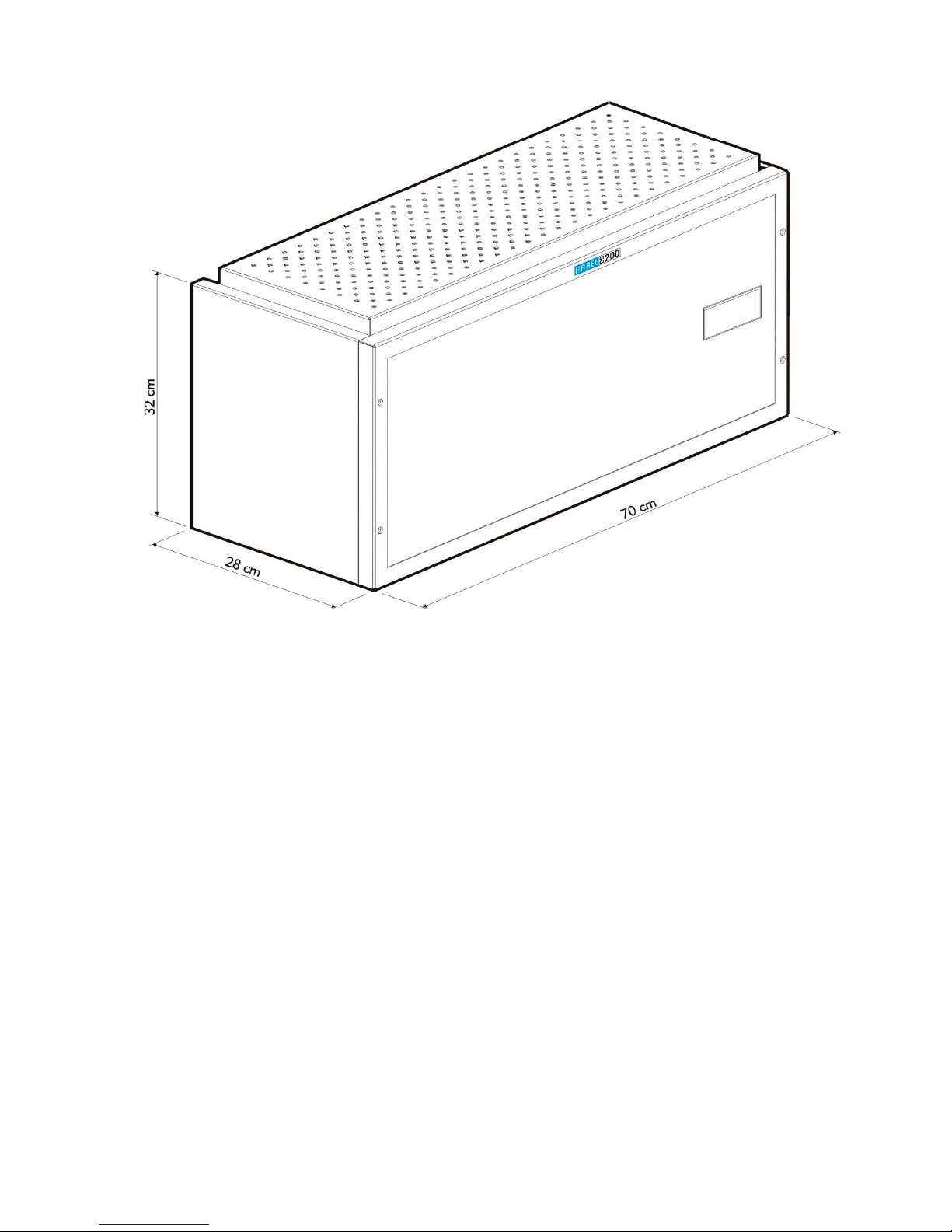
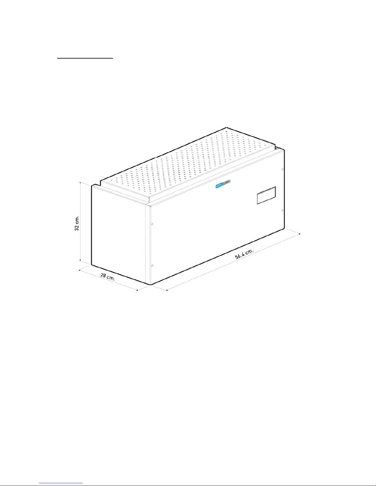
DS200 can be configured in two different mechanical structures, namely wall or cabinet type:
The wall-type DS200 can be configured in two structures: the single-rack type (with cover)
which can be extended to a maximum of 224 lines, and the two-rack type (with cover) which
can be extended to a maximum of 448 lines. As for the cabinet-type DS200, it can be
configured in the following structures:
- Single-rack (224 lines at the maximum),
- Two-rack (448 lines at the maximum),
- Three-rack (672 lines at the maximum),
- Four-rack (896 lines at the maximum),
- Five-rack (1120 lines at the maximum),
- Six-rack (1344 lines at the maximum)
In that structure, the system can reach a capacity of six racks by the use of two cabinets.
The figures below illustrate general appearances of the wall-type DS200 system and the
cabinet.
Page 17
DS Series PBX Technical Reference And Installation Guide
7
Page 18
8
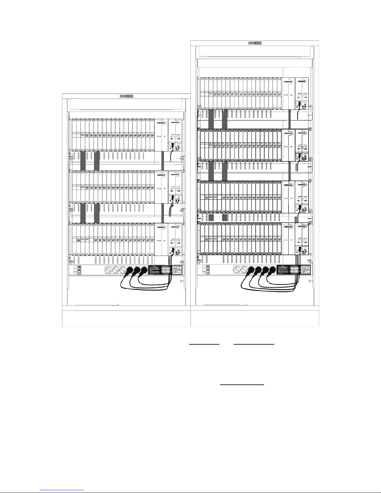
Racks constitute the basis of the mechanical structure of DS200. There are two types of rack
structure used in the DS200 systems, namely Main Rack and Auxiliary Rack
.
The both types of racks have 14 general-purpose slots for the same EX200 interfaces;
however, the CPU200 and DS200 CPUKON cards are situated only in the main rack.
Therefore, there are special slots for these cards in the main rack, whereas those slots are
not present in auxiliary racks. As a result, backplanes of the main rack and auxiliary racks
are different (BPL200-MAIN and BPL200-AUX) and they cannot be used interchangeably.
Page 19
DS Series PBX Technical Reference And Installation Guide
9
I.2. DS200S
DS200S is a medium-capacity digital telephone branch exchange in a single-rack structure,
which has been designed to be mounted on wall, and whose capacity can be extended to
224 lines. Similar to DS200 system, DS200S supports 750 IP ports. Due to its distributed
CPU structure, it is a very reliable and flexible communication system that is open to
development.
The figure below illustrates the general appearance of the DS200S system.
DS200S
Page 20

10
I.3. DS200M
DS200M is a medium-capacity digital telephone branch exchange in a single-rack structure,
which has been designed to be mounted on wall, whose capacity can be extended to 144
lines. Similar to DS200 system, DS200M supports 750 IP ports. Due to its distributed CPU
structure, it is a very reliable and flexible communication system that is open to development.
The figures below show the general appearance of the DS200M system.
DS200M
Page 21
DS Series PBX Technical Reference And Installation Guide
11
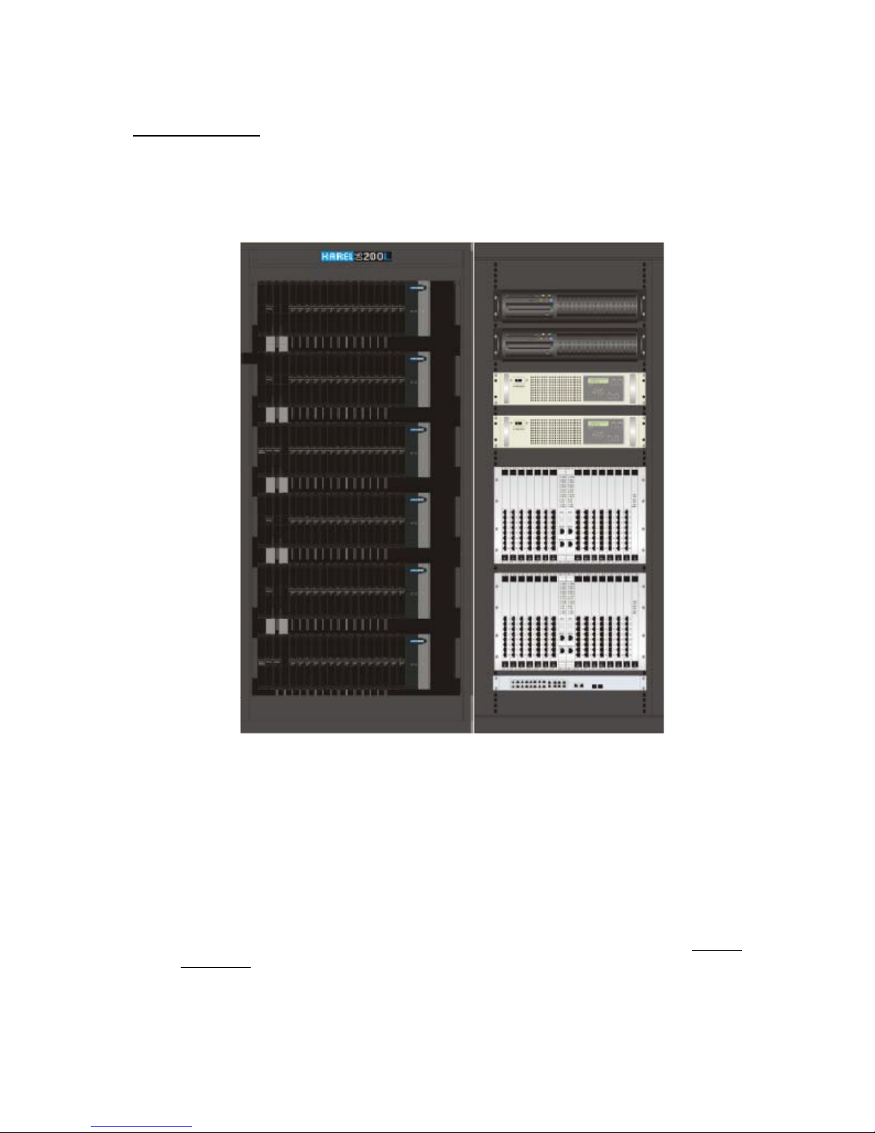
I.4. DS200L
The system hardware consists of TW200 (Tower200) towers, the PCU200 (PC Unit) Block,
the DCC Block, a network switch, power inverter and the external power block ( if SPS200 is
not used). In the figure below, DS200L system in a 6-rack and 19” cabinet is illustrated.
(There are 2 TW200 towers in the figure).
Fundamental differences of the DS200L system from the DS200 system are briefly as
follows:
• DS200L has high capacity up to 32000 ports,
• The PCU200 Block fulfills the tasks of the CPU200 card,
• DS200L has the DCC Block for high capacity switching,
• The units communicate over LAN with TCP/IP protocol,
• It is necessary to install Utility 4E1 cards on UTIL200 cards,
• It is possible to utilize the CC cards in main racks, instead of the CPU200 card ,
• External power block is utilized instead of the SPS200 power supply at high
capacities,
• DS200L utilizes power inverter and network switch.
Page 22

12
I.5. COMMON UNITS
DS200S and DS200M exchanges are two systems that have been designed to meet different
capacity needs, although they have the same structure. In this regard, it is a natural fact that
many units are employed in both exchanges. Such common units are called ‘the DS200S
unit’ throughout the rest of the guide; so one should keep in mind that the units mentioned in
this way can be employed in both the DS200S and the DS200M exchanges.
The EX200 Expansion Modules and the EVM200L modules listed below can be installed in
the general-purpose slots that are present in racks of the entire exchanges of the DS200
series:
• EX200 (0/16R) Analog Enhanced Extension Module
• EX200 (0/16C) Analog Extension Module With Caller ID
• EX200 (8+/0) Analog Expendable Line Card With Caller ID
• EX200 (CAS3B/0) CAS Signalling Line Module
• EX200 (0/8S0) ISDN BRI Extension Module
• EX200 (1E1/0) PRI / R2 /QSIG Switchable E1 Line Module
• EX200 (0/8KoU) Digital Extension Module
• EX200 (0/16KoU) Digital Extension Module
• EX200 (8T0/0) ISDN BRI External Line Module
• EX200 (0/8LB) Local Battery Telephone Extension Module
• EX200 (4VoIP) Voice Over IP Module
• EX200 (8VoIP) Voice Over IP Module
• EX200 (16VoIP) Voice Over IP Module
• EX200 (MGW1) Media Gateway Module
• EX200 (MGW2) Advanced Media Gateway Module
• EX200 (4TWT) Special Duplex External Line Module
• EX200 (8TWT) Special Duplex External Line Module
• EX200 (4E&M/0) External Line Module
• EX200 (8E&M/0) External Line Module
• EX200 (4PLC/0) External Line Module
• EX200 (ALARM) Alarm Module
• EVM200L Auto Attendant and Voice Mail Module
Page 23
DS Series PBX Technical Reference And Installation Guide
13
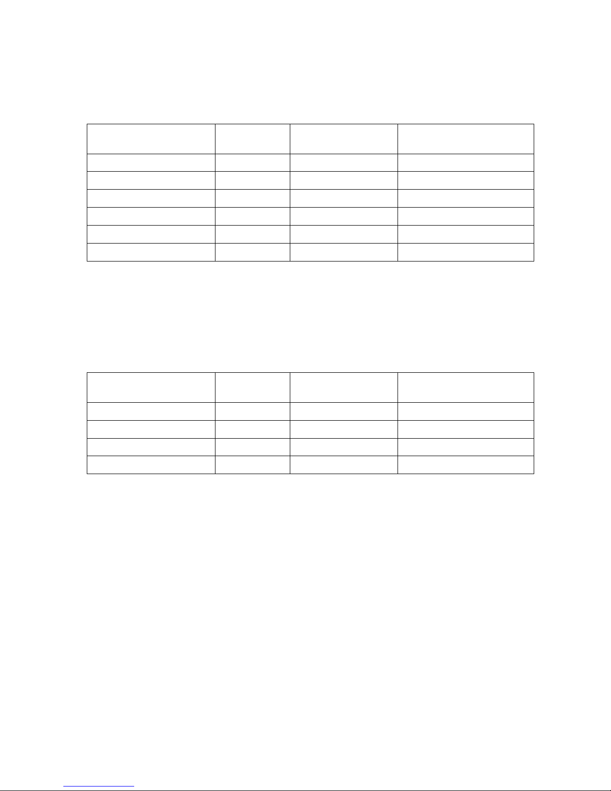
The system can be configured so as to include any combination of the modules above. The
table below shows the maximum number of each TDM line type that can be installed in a
system:
Module
Minimum
number Hardware Increments
The maximum number of
lines
Analog extensions 0 16 1200
Digital extensions 0 8 ,16 256
All Trunks 0 4, 8, 32 640
Analog Trunks 0 4, 8 256
Digital Trunks 0 8, 32 600
AA + VM Channels 0 4(record) / 4(play) 32(record) / 32(play)
Note: The limitations above are also valid for two towers of DS200L system. As the number
of towers increases the limits increase proportionally.
In addition to the TDM lines given above the table below shows the number of IP channels
available on a system:
Module
Minimum
number License Options
The maximum number of
channels
IP extensions 0 1, 5, 10, 100, 500 750
IP Trunks channels 0 1, 5, 10, 100 256
IP Trunk routes 8 - 8
Media Gateway channels 0 4, 8, 12, 24... 256
In addition to the common use of several cards, the software structures of the entire
exchanges of the DS200 series are the same. Hence, the codes and the ways of application
of all user and programming features are the same.
Likewise, all of the accessories introduced at the beginning of this guide are common to the
entire exchanges of the DS200 series.
Page 24

14
II. FUNDAMENTAL HARDWARE STRUCTURE
II.1. DS200
The DS200 system has been designed in a way that allows it to be configured in four
different basic structures, so that it can be installed in the most convenient way towards the
customer demands.
II.1.A. WALL-TYPE RACKS:
The wall-type racks provide the small-size exchanges with the hardware to fix them by
hanging them on walls. They are equipped with covers for the sake of safety.
The main rack of the wall-type DS200 system is composed of the parts listed below:
• RACK200 basic metal rack structure
• CS200 metal casing
• SPS200 AC/DC Power Supply
• SPS 248 DC/DC Power Supply
• BPL200-MAIN Backplane
• BPL200-SPS Backplane or BPL200-SPSX Backplane
• The CPU200 Central Processing Unit, the Redundant CPU200 Central
Processing Unit (optional), the DS200 CPUCON CPU Connection Card and the
DS200 CPU-FC CPU Flat Cable
• The UTIL200 Utility Card
• The EX200 Expansion Modules (at most 14 modules)
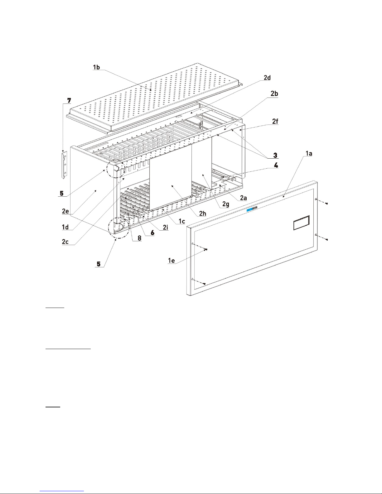
The figures below illustrate the major mechanical and electronic parts of the main rack of the
wall-type DS200 exchange.
Page 25
DS Series PBX Technical Reference And Installation Guide
15
A- DS200 Rack (With cover) B- SPS200 C- SPS248 D- CPU200
E- DS200 CPUKON F- UTIL200 G- BPL200
Page 26
16
Covers
1a- Front Cover 1b- Top Cover 1c- Bottom Cover
1d- Back Cover 1e- Front Cover Bolts
Parts of the Rack
2a- Lower Front Part of the Rack 2b- Upper Front Part of the Rack 2c- Lower Back Part of the Rack
2d- Upper Back Part of the Rack 2e- Left Side Cover 2f- Right Side Cover
2g- Rack Partitioning Piece
2h- Front Rack Support Holder
(During Shipment)
2i- Bottom Cover Support Piece
Other
3- SPS Fixing Screws 4- Grounding Screw 5- Bottom/Top Cover Grounding Cables
6- Card Slot 7- Wall Mount Bar 8- Cable Guide
Page 27
DS Series PBX Technical Reference And Installation Guide
17
Auxiliary rack of the wall-type DS200 system is composed of the parts listed below:
• RACK200 basic metal rack structure
• SPS200 AC/DC Power Supply
• SPS 248 DC/DC Power Supply
• BPL200-AUX Backplane
• BPL200-SPS Backplane or BPL200-SPSX Backplane
• UTIL200 Utility Card
• EX200 Expansion Modules (At most 14 modules)
Note that structures of the first rack (the main rack) and structures of the second, third, fifth
and the sixth racks (auxiliary racks) are different. (There are no CPU200 and DS200
CPUKON cards in the auxiliary racks.)
II.1.B. CABINET-TYPE RACKS
Racks (the main rack and the auxiliary rack) of the cabinet-type DS200 system include the
entire modules that have already been specified for the wall-type DS200, except the CS200
covers. This system is presented for use in a metal cabinet instead of CS200_ that may
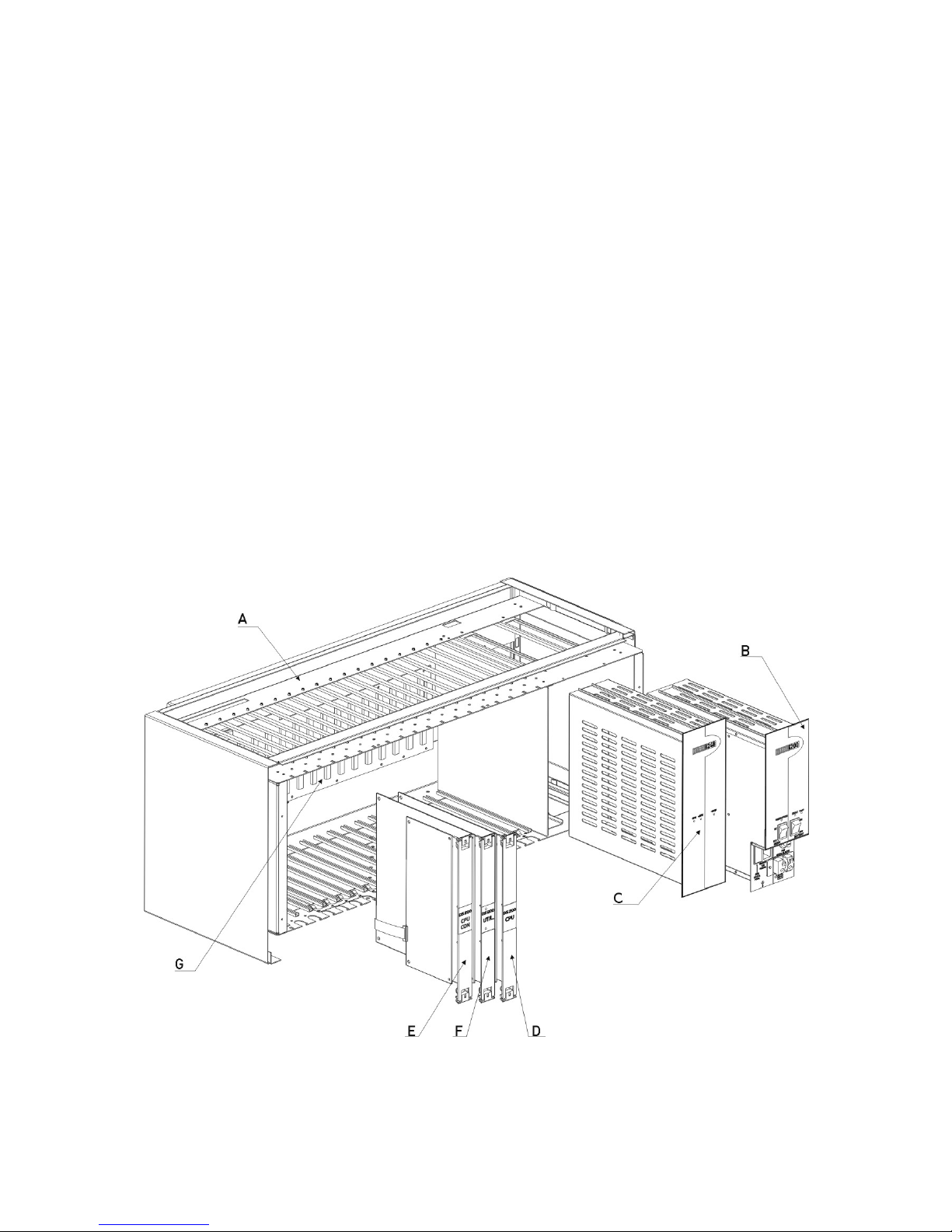
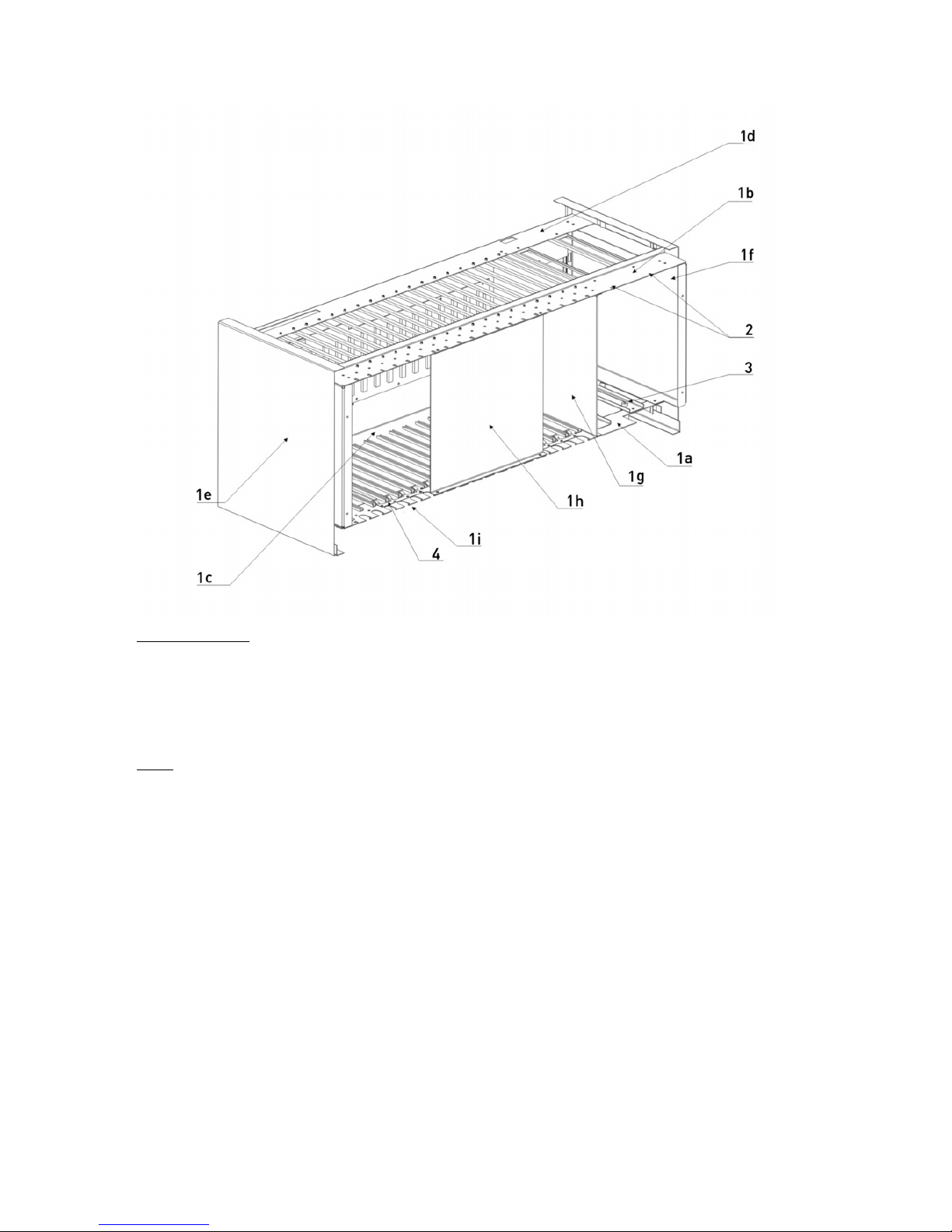
contain three or four racks. The figures below show the details of major mechanical and
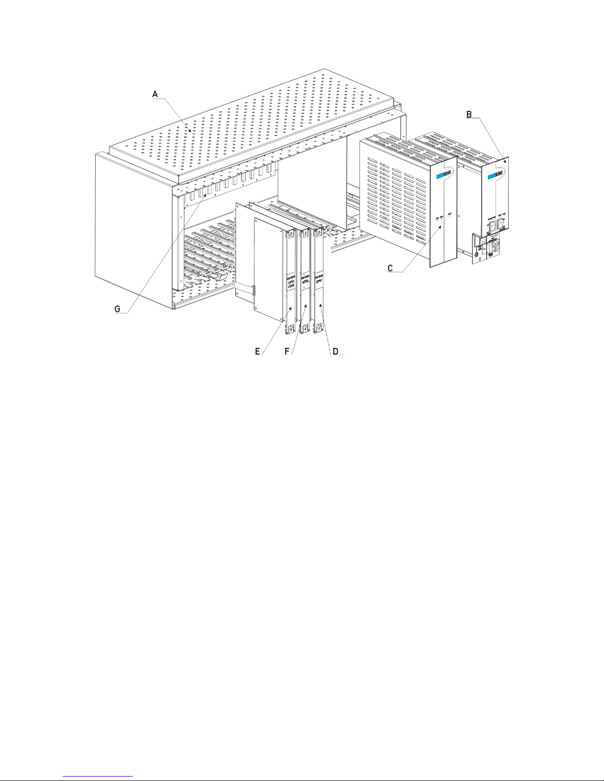
electronic parts of the main rack of the cabinet-type DS200 exchange.
A- DS200 Rack (Without cover) B- SPS200 C- SPS248
D- CPU200 E- DS200 CPUKON F- UTIL200
G- BPL200
Page 28
18
Parts of the Rack
1a- Lower Front Part of the Rack 1b- Upper Front Part of the Rack 1c- Lower Back Part of the Rack
1d- Upper Back Part of the Rack 1e- Left Side Cover 1f- Right Side Cover
1g- Rack Partitioning Piece 1h- Support Holder (During Shipment)
Other
2- SPS Fixing Screws 3- Grounding Screw
In addition to those, there are some cables that are used for inter-rack connections, whose
details are explained in later sections. These are:
• BPL200-FC, connection cable between the BPL200-MAIN and BPL200-AUX
backplanes
• BPLSPS-FC, connection cable among BPL200-SPS backplanes
Page 29
DS Series PBX Technical Reference And Installation Guide
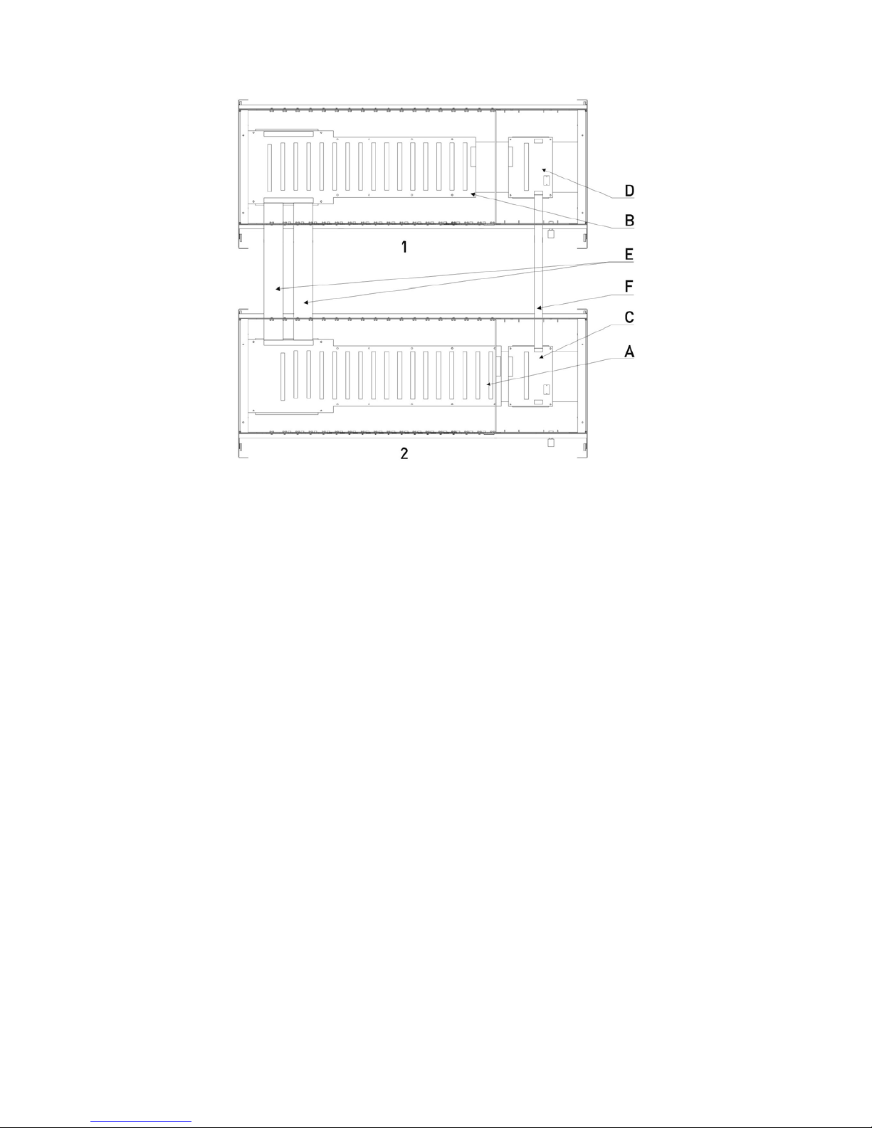
19
1 – Auxiliary Rack C – BPL200-SPS (Main Rack)
2 – Main Rack D – BPL200-SPS (Auxiliary Rack)
A – BPL200-MAIN E – BPL200-FC
B – BPL200-AUX F – BPLSPS-FC
II.1.C. AUXILIARY PARTS FOR THE CABINET-TYPE
FOURTH RACK
Mechanical structure of the fourth rack, which has been designed to be used in two-cabinet
configurations, is the same as that of the main rack; however, it does not include CPU200
and DS200 CPUKON cards. Instead, it contains the supplementary units listed below:
• Clock Master card
• CCU card
• Clock Slave card
• BPLSPS-FCX, inter-cabinet power connection cord
• PCM carrier cables
• BPL200-FC Flat connection cable
Page 30
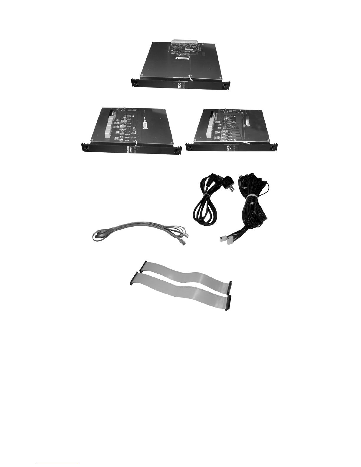
20
The CCU card
The Clock Master Card The Clock Slave Card
The PCM Carrier Cable BPLSPS-FCX
BPL200-FC
Related units shall be mentioned with these names in the remaining part of this guide.
II.1.D. CABINET
Cabinet is a metal closet, which encloses racks in systems with two or more racks; which
facilitates mounting operation; which includes special compartments for batteries and the
distribution frame (MDF); which is self-lit and ventilated by fan. It is manufactured in sizes
capable enough to contain three and four racks, in order to meet different capacity demands.
Page 31

DS Series PBX Technical Reference And Installation Guide
21
II.1.D.1. THE THREE-RACK CABINET:
It includes three rack slots to install a system of at most three racks. Two such cabinets are
used in order to configure systems with five or six racks.
Details of the parts in a three-rack cabinet are illustrated in the figure below.
1. Back cover 8. Grounding terminal 15. Fan
2. Outlet group 9. Shelf 16. Rack fixing screw
3. Grounding metal 10. Wheel 17. Rack slot (right)
4. Side cover (left) 11. Wheel cover 18. DS200 logo sticker
5. Metal strut 12. Side cover (right) 19. Front cover
6. Rack slot (left) 13. Main framework 20. Halogen lamp
7. MDF panel 14. Fan unit 21. Perpendicular cable holder
Page 32

22
II.1.D.2. THE FOUR-RACK CABINET:
It includes four rack slots that are required to install a system of at most four racks. This
cabinet is used in four-rack systems.
Details of the parts in a four-rack cabinet are illustrated in the figure below.
1. Back cover
8. Grounding terminal 15. Fan
2. Outlet group
9. Shelf 16. Rack fixing screw
3. Grounding metal 10. Wheel 17. Rack slot (right)
4. Side cover (left) 11. Wheel cover 18. DS200 logo sticker
5. Metal strut 12. Side cover (right) 19. Front cover
6. Rack slot (left) 13. Main framework 20. Halogen lamp
7. MDF panel 14. Fan unit 21. Perpendicular cable holder
Page 33

DS Series PBX Technical Reference And Installation Guide
23
II.1.E. INTER-CABINET CONNECTION UNITS
If the required DS200 capacity necessitates a configuration with four or more racks, such a
structure is accomplished by some intelligent units of the racks located in both cabinets,
which connect the two cabinets to each other.
In order for the inter-cabinet connections to be made, the revision of the CPU200 card must
be R01C.01 or higher, and the revision of the BPL200-MAIN backplane must be R03B.02 or
higher.
Information about the cards used for that purpose is as follows.
II.1.E.1. CCU CARD
The CCU card is a card employed in the second three-rack cabinet, which receives signals
from the CPU200 card located in the first three-rack block, and which distributes these
signals to the second block after amplifying them. Due to its structure, it is attached to the
special slot reserved for the CPU200 in the main rack of the second block and it transports
the signals to the second block over a 64-pin female connector at its back.
The LED on the front face of the CCU card blinks during normal operation.
II.1.E.2. CLOCK MASTER & CLOCK SLAVE CARDS
The Clock Master is installed in the block in which the CPU200 card is located and the Clock
Slave is installed in the block in which the CCU card has been installed. Since there is no
connector at the back of these cards to provide connection to the backplane, they can be
attached in any vacant slot in the system, which is easily reachable in order to facilitate
mounting. (See the DS200 Series Installation Guide, for the convenient slots)
These two cards function as a bridge carrying the PCM channels between the cabinets. The
necessary connections between the cards are made through special cables provided by
Karel.
Five identical eight-wire cables with RJ45 connectors at both ends are used for those
connections. As can be deduced from that fact, number of signals carried between the two
cards is (8 x 5) 40. Indeed, the number of signals that is to be used actively is 20, however, a
ground line is carried with each signal in order to increase the reliability of the carried signals,
so that the signals are affected by the external factors at a minimum.
Page 34

24
II.2. DS200S
The rack of DS200S provides the hardware to fix the exchange by hanging it on a wall. It is
equipped with covers for the sake of safety.
The rack of the DS200S system is composed of the parts listed below:
• RACK200S basic metal rack structure
• CS200S metal casing
• SPS200M AC/DC, DC/DC Power Supply
• BPL200S Backplane
• BPL200S-SPS Power Supply Backplane
• CPU200S Central Processing Unit, DS200S CPUCON CPU Connection Card
and DS200 CPU-FC CPU Flat Cable
• EX200 Expansion Modules (14 modules at the maximum)
The figure below illustrates the major mechanical and electronic parts of the rack of the
DS200S exchange.
Page 35

DS Series PBX Technical Reference And Installation Guide
25
1- Front Cover 1a – On/Off Switch Access Gap 2- Top Cover
3- Bottom Cover 4a- Left Side Cover 4b – Right Side Cover
5a- Upper Front Part of the Chassis 5b- Lower Back Part of the Chassis 5c- Upper Back Part of the Chassis
5d- Lower Front Part of the Chassis 6 – Card Slot 7 – Wall Mount Bars
A – DS200S CPUKON Card B – CPU200S Card C – CPU200-FC Flat Cable
D – EX200 Card E – SPS200M F – BPL200S-SPS Backplane
G- BPL200S Backplane
Page 36

26
II.3. DS200M
The rack of DS200M provides the hardware to fix the exchange by hanging it on a wall. It is
equipped with covers for the sake of safety.
The rack of the DS200M system is composed of the parts listed below:
• RACK200M basic metal rack structure
• CS200M metal casing
• SPS200M AC/DC, DC/DC Power Supply
• BPL200M Backplane
• BPL200M-SPS Power Supply Backplane
• CPU200S Central Processing Unit, DS200S CPUCON CPU Connection Card
and DS200 CPU-FC CPU Flat Cable
• EX200 Expansion Modules (9 modules at the maximum)
The figure below illustrates the major mechanical and electronic parts of the rack of the
DS200M exchange.
Page 37

DS Series PBX Technical Reference And Installation Guide
27
1- Front Cover 1a – Front Cover Fixing Screw 2- Top Cover
3- Bottom Cover 4- Right Side Cover 5- Left Side Cover
6a- Upper Back Part of the Chassis 6b- Upper Front Part of the Chassis 6c- Lower Front Part of the Chassis
6d- Lower Back Part of the Chassis 7- Card Slot 8- Back Cover
A- DS200S CPUKON Card B- CPU200S Card C- SPS200M Power Supply
D- BPL200M Backplane E- BPL200M-SPS Backplane
Page 38

28
II.4. DS200L
Six-rack cabinets are used in the DS200L systems. 2 of TW200 towers can be installed into
six-rack cabinet. The rack structure of TW200 is similar to the usual DS200 rack structure.
The main differences are that; CC card is used instead of CPU200 and Utility 4E1 card can
be mounted on to the UTIL200 card. Furthermore, redundant CC card can not be installed. 1
TW200 tower consists of 1 main rack and maximum 2 auxiliary racks. TW200 racks consist
of the parts below:
• RACK200 basic metal rack structure
• SPS200 AC/DC Power Supply (for small capacities)
• SPS248 DC/DC Power Supply
• BPL200-AUX Backplane (only for auxiliary rack)
• BPL200-MAIN Backplane (only for main rack)
• BPL200-SPS Backplane or BPL200-SPSX Backplane
• CC communication unit, the CPUKON Card and the DS200 CPU-FC CPU Flat Cable
• The UTIL200 Utility Card and the Utility 4E1 card
• The EX200 Expansion Modules (at most 14 modules)
II.4.A. RACK STRUCTURE OF TW200 (TOWER 200)
A TW200 tower consists of maximum 3 TW200 racks, namely a main rack and two auxiliary
racks. (In fact, only a single main rack is enough to establish a tower.) The rack structure of
TW200 is same as the DS200 rack structure (see section II.1.B). The UTIL200, CPUKON
and other cards that are used in DS200 racks are also used in TW200 racks. However, since
the PCU Block functions as the main processor in the DS200L system, no CPU200 card is
available. The CC200 card is employed instead of the CPU200 card. Necessary information
on the CC200 and UTILITY 4E1 cards are supplied below.
II.4.B. THE SIX-RACK CABINET
Six rack slots are available in this cabinet, which are required to install a system with at most
six racks. Hence, it is used for six-rack systems. Two TW200 towers of the DS200L systems
can be placed in a 6-rack cabinet.
Details regarding the elements of a 6-rack cabinet have been illustrated in the figure below.
Page 39

DS Series PBX Technical Reference And Installation Guide
29
1. Rear cover 11. Allen screw 21.Switch
2. Side covers 12. DS200L Logo sticker 22.Fixing clip
3. Metal strut 13. Front cover 23.Grounding clip
4. Rack slot (left)
14. Perpendicular cable holder
(narrow)
24.Circuit breaker
5. Rack slot (right)
15. Perpendicular cable holder
(wide)
25.Screw
6. Panel 16. Lamp 26. Front cover
7. Foot 17. Clip slot 27.Cable output rubber
8. Main framework 18.Rubber cover 28.Feet cover
9. Fan unit 19.Clips (6-way) 29.Cable output panel
10.Fan 20.Switch plate
Page 40

30
III. BACKPLANES
III.1. DS200
III.1.A. BACKPLANE OF THE MAIN RACK - BPL200MAIN
Definition:
BPL200-MAIN constitutes the backbone of the main rack. It is the card, on which CPU200,
UTIL200, EX200 modules and the backplane of power supplies (the BPL200-SPS
backplane) are plugged, and it is the card that provides the fundamental communication of
the system, as well as the connection to the other racks. On the backplane, there are 14 card
connection slots for EX200, two for CPU200 and one for UTIL200. Besides, there are
connectors located on this card for the auxiliary rack and the SPS backplane.
The figure below shows structure of the BPL200-MAIN backplane and the connectors
located on it.
1. DS200 CPUKON Card Slot 3. SPS Backplane – BPL200-SPS
2. Main Rack Backplane - BPL200-MAIN f. SPS248 Connector
a. UTIL200 Module Connector g. SPS200 Connector
b. CPU200 Module Connector h. Inter-rack SPS Connector
c. General-purpose Connectors 4. Grounding Screw
d. SPS Backplane Connector 5. Top Cover Ground Connection
e. Inter-rack Backplane Connector 6. Bottom Cover Ground Connection
7. Clock-Master Card Slot in systems with four or more racks
BPL200-MAIN has been mounted between the upper and lower back parts in the metal rack.
The connectors on BPL200-MAIN completely fit the card slots in order to facilitate plugging of
modules.
Dimensions of the BPL200-MAIN backplane are 50 cm. x 14.8 cm and it weighs 0.4 kg.
Page 41

DS Series PBX Technical Reference And Installation Guide
31
III.1.B. BACKPLANE OF THE AUXILIARY RACK –
BPL200-AUX
Definition:
Framework of the auxiliary racks is the BPL200-AUX backplane. The UTIL200, EX200 and
BPL200-SPS backplane modules are connected over this backplane. The BPL200-AUX
backplane differs from the BPL200-MAIN backplane in some ways. There are no CPU200
and DS200 CPUKON connection slots on this card.
The figure below shows the BPL200- AUX Backplane and the connectors located on it.
1. Auxiliary Rack Backplane – BPL200-AUX 2. SPS Backplane – BPL200-SPS
a. UTIL200 Module Connector c. Auxiliary Rack Backplane Connector
b. General-purpose Connectors e. Inter-rack SPS Connector
c. SPS Backplane Connector f. SPS248 Connector
d. Inter-rack Backplane Connector 3. Grounding screw
4. Bottom Cover Ground Connection
5. Top Cover Ground Connection
BPL200-AUX has been mounted between the upper and lower back parts in the metal rack.
The connectors on BPL200-AUX completely fit the card slots in order to facilitate plugging of
modules.
Dimensions of the BPL200-AUX backplane are 46 cm x 14.8 cm and it weighs 0.4 kg.
Page 42

32
III.1.C. BACKPLANE OF POWER SUPPLIES–BPL200SPS
Definition:
The SPS200 and SPS248 power supply modules are connected to the BPL200-SPS
backplane.
The BPL200-SPS cards in the main rack and in the auxiliary racks are almost the same
except a slight difference. The BPL200-SPS backplane end of the cable, which provides
connection between the BPL200-SPS backplane and BPL200-MAIN in the main rack, has
been fixed to the backplane. On the other hand, that end has not been fixed to the backplane
in the auxiliary rack; it is rather connected to the card by a connector.
The figure below shows the connectors on BPL200-SPS and their explanations.
1 Inter-rack SPS Connector 5 Special connector for inter-rack cabling
2 Inter-rack SPS Connector 6 SPS200 Connector
3 BPL200 Backplane Connector 7 Alarm Connector
4 SPS248 Connector
BPL200-SPS has been mounted between the upper and lower back parts in the metal rack.
The connectors on BPL200-SPS completely correspond to the module slots in order to
facilitate plugging of the SPS200 and SPS248 modules.
Dimensions of the BPL200-SPS backplane are 12 cm x 9 cm and it weighs 0.1 kg.
Page 43

DS Series PBX Technical Reference And Installation Guide
33
III.1.D. BACKPLANE OF POWER SUPPLIES WITH
BACKUP – BPL200-SPSX
Definition:
Two SPS248 power supply modules are connected to the BPL200-SPSX backplane. This
backplane is an alternative to the BPL200-SPS backplane. It is employed for backing up the
SPS248 power supply for each rack, in cases where the exchange is fed by an external
power supply.
The BPL200-SPSX cards in the main rack and in the auxiliary racks are almost the same
except a slight difference. The BPL200-SPSX backplane end of the cable, which provides
connection between the BPL200-SPSX backplane and BPL200-MAIN in the main rack, has
been fixed to the backplane. On the other hand, that end has not been fixed to the backplane
in the auxiliary rack; it is rather connected to the card by a connector.
The figure below shows the connectors on BPL200-SPSX and their explanations.
1 Inter-rack SPS Connector 4 SPS248 Connector
2 Inter-rack SPS Connector 5 SPS248 Connector
3 BPL200 Backplane Connector
BPL200-SPSX has been mounted between the upper and lower back parts in the metal rack.
The connectors on BPL200-SPSX completely correspond to the module slots in order to
facilitate plugging of the SPS248 modules.
Dimensions of the BPL200-SPSX backplane are 12 cm x 9 cm and it weighs 0.1 kg.
Page 44

34
III.2. DS200S
III.2.A. BPL200S
Definition:
The backplane constitutes the backbone of the main rack. It is the card, on which CPU200S,
EX200 modules and the backplane of power supplies (the BPL200S-SPS backplane) are
plugged, and it is the card that provides the fundamental communication of the system. On
the backplane, there are 14 card connection slots for EX200 cards and 1 connection slot for
CPU200S. Besides, there is a connector for the SPS backplane.
The figure below shows structure of the BPL200S backplane and the connectors located on
it.
DS200S
1.BPL200S Backplane 2. SPS Backplane – BPL200S -SPS
a. CPU200S Module Connector c. BPL200S/M Connector
b. General-purpose Connectors d. HR08 Power Connector
c. SPS Backplane Connector e. SPS200M Connector
3. Grounding screw 4, DS200S CPUKON Card Slot
The backplane has been mounted between the upper and lower back parts in the metal rack.
The connectors on the backplane completely correspond to the card slots in order to
facilitate plugging of modules.
Dimensions of the BPL200S backplane are 40 cm x 11.5 cm and it weighs 0.3 kg.
Page 45

DS Series PBX Technical Reference And Installation Guide
35
III.2.B. BACKPLANE OF THE POWER SUPPLY–
BPL200S-SPS
Definition:
The power supply module of the exchange is connected to the Power Supply backplane.
The Power Supply backplane has been mounted between the upper and lower back parts in
the metal rack. The connector on the backplane fully corresponds to the module slot in order
to facilitate plugging of the power supply module.
Dimensions of the BPL200S-SPS backplane are 11.5 cm x 4.5 cm and it weighs 0.1 kg.
III.2.B.1. HR08 POWER FAILURE TRANSFER STATION
RELAY MODULE CONNECTOR
If the batteries exhaust due to prolonged power failures that affect the DS200S exchange,
then the connection of the exchange with the outer world may completely cease. In order to
prevent such a case, the HR08 module can be installed, so that desired extensions are
transferred to desired lines in the event that the DS200S exchange has become completely
off line.
The HR08 connector on the BPL200S-SPS backplane is used to put HR08 into operation
when the exchange battery gets into the low current cut-off mode (i.e., when the exchange
has been shut down).
Pinouts for the HR08 connector are as in the table below:
Pin no Signal
1 Shut
2 -48VDC
Page 46

36
III.3. DS200M
III.3.A. BPL200M
Definition:
The backplane constitutes the backbone of the main rack. It is the card, on which CPU200S,
EX200 modules and the backplane of the power supplies (the BPL200S-SPS backplane) are
plugged, and it is the card that provides the fundamental communication of the system. On
the backplane, there are 9 card connection slots for EX200 cards and one connection slot for
CPU200S. Besides, there is a connector for the SPS backplane.
The figure below shows structure of the BPL200M backplane and the connectors on it.
DS200M
1. BPL200M Backplane 2. SPS Backplane – BPL200S-SPS
a. CPU200S Module Connector c. BPL200S/M Connector
b. General-purpose Connectors d. HR08 Power Connector
c. SPS Backplane Connector e. SPS200M Connector
3. Grounding screw 4, DS200S CPUKON Card Slot
The backplane has been mounted between the upper and lower back parts in the metal rack.
The connectors on the backplane completely correspond to the card slots in order to
facilitate plugging of modules.
Dimensions of the BPL200M backplane are 26.7 cm x 11.5 cm and it weighs 0.2 kg.
Page 47

DS Series PBX Technical Reference And Installation Guide
37
III.3.B. BACKPLANE OF THE POWER SUPPLY –
BPL200S-SPS
Definition:
DS200M and DS200S use the same power supply backplane. See section “BACKPLANE OF
THE POWER SUPPLY– BPL200S-SPS” for details.
III.4. DS200L
The main rack backplane (BPL200-MAIN), the auxiliary rack backplane (BPL200-AUX), the
power supplies backplane (BPL200-SPS) and the redundant power supplies backplane
(BPL200-SPSX), which are used in DS200 systems, are also used in the DS200L systems.
Details regarding those backplanes have been explained in previous chapters.
Page 48

38
IV. POWER SUPPLIES
IV.1. DS200
The system operates on 230 VAC / 50 Hz mains input that is processed by SPS200 and
SPS248 Power Supply modules. Therefore, a single SPS200 and an SPS248 have been
included in each rack within the basic hardware structure of the system.
Yet, the DS200 system can be fed by an external AC/DC power supply of 56 VDC, if
necessary. In that case, since the SPS200 AC/DC power supplies are not used, the SPS248
DC/DC power supplies may be used as a backup, upon wish. (In that case, the BPL200SPSX backplane must be used, too.)
IV.1.A. THE AC/DC POWER SUPPLY - SPS200
Definition:
SPS200 is a Switched Mode Power Supply that operates on the mains voltage (SMPS).
Appearance of the SPS200 AC/DC Power Supply is illustrated in the figure below.
A. Mains Side B. Battery Side C. Connection Plane
D. Control & Monitor Plane 1. Power Status LEDs 2. Battery On/Off Switch
3. Mains On/Off Switch 4. Battery Fuse 5. Mains Fuse Compartment
6. Mains Socket 7. Battery Connectors
The SPS200 AC/DC Power Supply converts 230 V AC to -56V DC, which is the input value
for the SPS248 DC/DC Power Supply. SPS200 can also feed the system through batteries
and it can charge the batteries while being fed from the mains. In addition to that, it protects
the exchange from adverse factors that may affect through the electric system.
Page 49

DS Series PBX Technical Reference And Installation Guide
39
Technical Information:
SPS200 operates on 230 VAC from the mains input. Its alternative current input has been
designed so as it is not affected by variations within the range +/- %10. There are two T-Type
2A / 250 VAC fuses in the main fuse compartment as the first-step protection for the phase
and neuter lines.
The SPS200 AC/DC Power Supply has been connected to the 5-pin connector on the
BPL200-SPS Backplane and it has been screwed into the upper front part of the metal rack.
The SPS fixing screw must be loosened before the SPS casing is removed from the
exchange. It is not obligatory to use that screw after mounting, which has been included just
to provide safety during transportation.
The SPS200 AC/DC Power Supply contains a metal casing to which the SPS200CR Power
Card is connected. The mains transformer is located on the SPS200CR Power Card.
SPS200CR, which gets 230 VAC over mains, generates –54 VDC, which is the input voltage
to SPS248. Pin-outs for the SPS200 connector on the BPL200-SPS backplane are as
follows:
SPS200 – BPL200-SPS Connector
Pin no
Signal
1 - 54 VDC
2 ISOGND
3 -54 VDC
4 ISOGND
5 - VOUTREL
The DS200 system may be backed up with the 48 VDC battery support in order to maintain
operation in case of power failures. Hence, the necessary battery backup circuitry is present
on SPS200CR. Since the system does not include embedded power failure transfer stations,
battery backup is vitally important for maintaining connection of the system to the outer world
in case of power failure. Considering the battery connection in this regard, use of dry-type
batteries is strongly recommended in order to maintain proper operation of the system. A
battery connection of 48V/24 Ah is recommended for a full capacity, three-rack system with a
traffic rate of 35 % in average.
There is also an F-Type 8A/48VDC fuse on SPS200 for the battery input.
SPS200CR has the ability to charge the batteries even when the system power is on and the
system is operating with a low traffic rate. In addition to that, there is also a low current cutoff circuit that turns itself off when the battery voltage drops below 42 VDC, and which is not
turned on until the voltage level rises above 48 VDC. Thanks to this circuit, SPS200 would
prolong life of the batteries by preventing their full discharge.
The counterpart of the SPS200 backplane connector (with 4 pins) is also located on the outer
side of the metal chassis on the back surface of the rack. Those connectors are also
supposed to be connected to one another during installation of systems with several racks,
with cables that come as attached to those connectors.
Page 50

40
Operational Information:
Three LEDs that are on the front panel of the SPS200 Power Supply Module help to figure
out the power supply that is in use at that moment.
The first of those LEDs is for 230 VAC (with the “Mains Power” tag), the second one is for –
56 VDC (with “VOUT” tag) and the third one is for fault detection (with “Fault” tag). When the
system is being fed from the mains supply during normal operation, the “Mains Power” and
“VOUT” LEDs light up. The “Mains Power” LED is turned off when the mains supply is cut. In
that case, if the battery backup is active, then the “VOUT” LED remains on. If a problem with
the system power occurs, the “FAULT” LED lights up. In that case, the system must be shut
down.
In a multi-rack system, there are several SPS200 Modules, which are connected to each
other in parallel over inter-rack SPS connections. Therefore, in normal conditions, if the
system traffic load is not extreme, just one or two of the SPS200 modules operate, while the
other(s) is (are) in standby mode. LEDs of the SPS200 that is in standby mode are off. Once
the SPS200 gets into operation, its LEDs are turned on.
There are also Mains and Battery On/Off switches on SPS200. In a wall-type system, those
switches are accessible even when the front cover is closed.
In a cabinet-type system, in addition to the on/off switches on SPS200, a primary mains
switch for mains input, which is protected by a 10 A / 250 VAC, T-type fuse, is situated in the
lower front section of the cabinet. Likewise, the primary battery switch, which is protected by
a 10 A / 250 VAC, T-type fuse, has been placed right below the primary mains switch. It is
required to open the front cover of the cabinet in order to reach primary mains and battery
switches.
Page 51

DS Series PBX Technical Reference And Installation Guide
41
The mains On/Off switch is supposed to be set to position “1” for normal operation.
Moreover, in order to put the battery into operation in the systems with battery connection in
case of power failures, the battery switch is also supposed to be set to position “1”. While the
system is being put into operation, the mains switch is supposed to be set to “1”, even in
cases where battery connection is present, and the battery switch is supposed to be set to
“1” after the system has started to operate.
* AS FOR THE CABINET-TYPE SYSTEMS, IN ORDER TO TURN ON/OFF
THE SYSTEM, THE PRIMARY MAINS AND THE PRIMARY BATTERY SWITCHES
MUST BE TURNED ON AND TURNED OFF, RESPECTIVELY. THE BATTERY AND
MAINS SWITCHES ON SPS200 ARE FOR SECONDARY CONTROL ONLY.
TURNING SPS200 SWITCHES ON AND OFF, BEFORE TURNING THE PRIMARY
MAINS AND THE PRIMARY BATTERY SWITCHES OFF, MAY DAMAGE SPS200.
Dimensions of SPS200 are 8 cm. x 22.5 cm. x 20 cm. and it weighs 2.8 kg.
Page 52

42
IV.1.B. THE DC/DC POWER SUPPLY - SPS248
Definition:
It is the power supply that generates voltages and the ringer signal, which are required for
the system, from - 56 VDC it receives from SPS200.
The figure below shows the appearance of the SPS248 DC/DC Power Supply.
The SPS248 DC/DC Power Supply converts the -56 VDC output of the SPS200 AC/DC
Power Supply to the voltage levels of +5 VDC, -5 VDC and -48 VDC that are required for
system operation. Besides, there is a ringer transformer on SPS248 for generating ringer
signal (67 Vrms.)
Technical Information:
The SPS248 DC/DC Power Supply is plugged into the 64-pin power connector that is on the
BPL200-SPS backplane and it is fixed to the upper front part of the metal rack with a screw.
The SPS248 DC/DC Power Supply contains a metal power rack onto which the SPS248CR
Power Card and the ringer transformer are connected.
Outputs of SPS248CR and the ringer transformer are transferred to the BPL200-SPS
backplane over the 64-pin power connector. The backplane carries these outputs to the
BPL200-MAIN / BPL200-AUX sections. Pin-outs for the SPS248 connector on the BPL200SPS backplane are as follows:
Page 53

DS Series PBX Technical Reference And Installation Guide
43
SPS248 – BPL200-SPS Connector
Pin Signal Pin Signal
64, 32 ACK-5 V 43-48,11-16 ISOGND
63, 31 ACK-48 V 42, 10 RING
59-62, 27-30 ISOGND 38-41, 6-9 ISOGND
55-58, 23-26 - 48 VDC 34-37, 2-5 + 5 VDC
49-54,17-22 - 56 VDC 1, 33 - 5 VDC
Operational Information:
There are three Power Status LEDs on the front panel of the SPS248 Power Supply. The
first, second and third LEDs are for -5 VDC, +5 VDC and -48 VDC, respectively. Normally, all
three LEDs are supposed to light up when the system power is switched on. If there is
problem with one of the DC voltages, then the related LED goes off.
Dimensions of SPS248 are 8.2 cm. x 22.5 cm. x 20 cm. and it weighs 3.15 kg.
Page 54

44
IV.2. DS200S & DS200M
IV.2.1. THE POWER SUPPLY - SPS200M
The DS200S and DS200M systems operate on the 230 VAC / 50 mains supply, which is
processed by the SPS200M Power Supply Module. SPS200M comes on a metal chassis
which is open at the top and all sides.
Definition:
SPS200M is a Switched-Mode Power Supply that operates on the mains voltage (SMPS).
A. Control & Monitor Plane B. Connection Plane C. Mains Side
D. Battery Side 1. Power Status LEDs 2. Battery On/Off Switch
3. Mains On/Off Switch 4. Battery Fuse 5. Mains Fuse Compartment
6. Mains Socket 7. Battery Connectors
The SPS200M AC/DC-DC/DC Power Supply first converts 230 V AC to –56 VDC within itself.
Then, it converts the -56 VDC output to the voltage levels of +5 VDC, -5 VDC and -48 VDC
that are required for system operation. Besides, there is a ringer transformer on it for
generating ringer signal (67 Vrms.) The power supply can also feed the system through the
battery and it can charge the battery while being fed from the mains voltage. In addition to
that, it protects the exchange from adverse factors that may affect through the electric
system.
SPS200M Power Supply contains a metal casing to which the Power Card is connected.
Page 55

DS Series PBX Technical Reference And Installation Guide
45
Technical Information:
SPS200M operates on 230 VAC from the mains. Its alternative current input has been
designed so as it is not affected by variations within the range +/- %10. There are two T-Type
2A / 250 VAC fuses in the main fuse compartment as the first-step protection for the phase
and neuter lines.
The SPS200M Power Supply has been connected to the 10-pin connector on the BPL200SSPS Backplane and it has been screwed to the upper front part of the metal rack. The SPS
fixing screw must be loosened before the SPS casing is removed from the exchange. It is not
obligatory to use that screw after mounting, which has been included to provide safety during
transportation.
Signals on the 10-pin connector, which is at the output of SPS200M:
SPS200M – BPL200S-SPS Connector
Pin no
Signal Pin no Signal
1 + 5 VDC 6 - 48 VDC
2 Ground 7 - 48 VDC
3 Ringer 8 Ground
4 PWR_DAT1 9 - 5 VDC
5 PWR_DAT0 10 Ground
The DS200S/DS200M system could be backed up with 48 VDC batteries in order to maintain
operation in case of power failures. Therefore, there is the necessary battery backup circuitry
on the power supply. Since the system does not have embedded power failure transfer
stations, battery backup is essentially important for maintaining connection of the system to
the outer world. Considering the battery connection in this regard, use of dry-type batteries is
strongly recommended in order to maintain proper operation of the system. A battery
connection of 48V/19 Ah is recommended for a full capacity system with a traffic rate of 35 %
in average.
There is also an F-Type 8A/48VDC fuse on the power supply for the battery input.
The power supply has the ability to charge the batteries even when the system power is on
and the system is operating with a low traffic rate. In addition to that, there is a low current
cut- off circuit that turns itself off when the system voltage drops below 34 VDC, and which is
not turned on until the voltage goes above 46 VDC. Thanks to this circuit, the power supply
would prolong life of the batteries by preventing their full discharge.
Operational Information:
Three LEDs that are on the front panel of the SPS200M Power Supply Module help figure
out the power supply that is in use at the moment.
The first of those is for 230 VAC (with the “Mains Power” tag), the second one is for –48 VDC
and the third one is for +5 VDC. When the system is being feed from the mains supply
during normal operation, all LEDs light up. The “Mains Power” LED is turned off in the
absence of mains voltage. In that case, if battery backup is available, then the LED for –48
VDC remains on. In the event that a problem with the + 5VDC supply in the system occurs,
the LED for + 5VDC goes off. If that is the case, the system must be shut down.
There are also Mains and Battery On/Off switches on SPS200M. In the DS200S/DS200M
system, those switches are accessible even when the front cover is closed.
Page 56

46
The Mains On/Off switch is supposed to be set to position “1”, for normal operation.
Moreover, in order to put the battery into operation in the systems with battery connection in
case of power failures, the battery switch is also supposed to be set to position “1”. While the
system is being put into operation, the mains switch is supposed to be set to position “1”,
even in cases where battery connection is present, and the battery switch is supposed to be
set to position “1”, after the system has started to operate.
Dimensions of SPS200M are 8,2 cm x 25.5 cm x 25 cm, and it weighs 2 kg.
IV.3. DS200L
IV.3.A. THE AC/DC POWER SUPPLY - SPS200
For small capacity DS200L systems, SPS200 power supplies are used. Details regarding
those power supplies have been explained in previous chapters.
IV.3.B. THE DC/DC POWER SUPPLY- SPS248
SPS248 power supplies are also used in the DS200L systems. Details regarding those
power supplies have been explained in previous chapters.
Page 57

DS Series PBX Technical Reference And Installation Guide
47
IV.3.C. THE EXTERNAL POWER BLOCK
In case of large capacity DS200L systems require high capacity battery groups, external
power supplies can be used instead of SPS200 power supplies.
For proper power regime, in addition to external power supplies the capacities of the
batteries must be selected appropriately for the system capacity.
External Power Block feeds DCC block, power inverter and the SPS248 power supplies
which are at the TW200 towers by -48V. Cabling is to be made from external power supply
to each tower and to other units.
IV.3.C.1. THE POWER INVERTER
For small capacity systems, in case system is fed by SPS200 power supplies, PCU Block
and network switch can get the required 220V AC voltage from the electricity network. In this
case, there will be no need for power inverter.
For large capacity systems, system gets -48V voltage from the external power supply, -48V
coming from External power block is converted to 220V AC and transmitted to PCU200
block, redundant PCU200 block and network switch. Power inverters are located in the 19”
cabinet. Optionally, redundant power inverter can be installed to the system. At the systems
which have redundant power inverter, in case any problem with any of the power inverter
occurs, the redundant power inverter is put into operation. Thus, PCU200 blocks and
network switch get the 220V AC input from the redundant one and keep operating without
any problem.
Inverter and redundant one for DS200L system are shown below.
Page 58

48
V. CENTRAL PROCESSING MODULE - CPU &
CPU CONNECTION CARD - CPUKON
V.1. DS200
V.1.A. CPU200 MODULE
Definition:
The CPU200 Central Processing Module is the brain of the system. It includes
microprocessor and memory circuits on it. CPU200 is present only in the main rack and it is
plugged into the card slot that is fourth from the left.
Page 59

DS Series PBX Technical Reference And Installation Guide
49
Technical Information:
The CPU200 module consists of two different cards. The card at the bottom has the address
and data buses that carry the required signals to the main rack of the exchange, whereas the
upper one contains the entire memory elements and the Power PC (PPC) 850 processor
circuits. The PPC is a RISC based processor of 80 MIPS processing power.
The CPU200 Module is plugged into the corresponding 64-pin connector on the BPL200MAIN backplane and it is fixed to the upper and lower front sections of the metal rack
through the fixing latches that are on the front card cover.
CPU200 contains memory elements such as 32 MB FLASH ROM, 256 MB DRAM and
EEPROM, as well as the ICP (Intra-rack Communication Protocol). In addition to that,
CPU200 is responsible for generation of system clock pulses.
CPU200 generates address and data signals, which are required for the UTIL200 and EX200
Modules. It transmits those signals to BPL200-MAIN over a 64-pin connector, and to the
BPL200-AUX backplane over the two 34-pin connectors that provide the BPL200-MAIN BPL200-AUX connection, and to the second cabinet over a 34-pin connector that is
employed for that transmission when required.
Data signals which are essential to the entire accessories are generated on CPU200 and
then they are transmitted to DS200 CPUKON over DS200 CPU-FC.
Operational Information:
A LED is situated on the front panel of CPU200. This LED continuously blinks during normal
operation. On the other hand, it remains on during a reset or parameter transfer. By this
way, the status of the system can be monitored through this LED.
The CPU200 card has two Ethernet connectors. One is for a PC connection for maintenance,
programming, etc and for IP extensions. The other one is for IP trunks.
* CPU200 MUST NOT BE REMOVED WHILE THE SYSTEM IS OPERATING.
Dimensions of CPU200 are 20 cm. x 22.5 cm. and it weighs 0.3 kg.
Page 60

50
V.1.B. REDUNDANT CPU200 MODULE
Definition:
The redundant CPU200 module has structurally no difference compared to the CPU200
module; it is just an optional module that could be employed for backing up the CPU200 card
in the system against possible problems.
Technical Information:
In the systems with the redundant CPU200 module, two CPU200 cards are installed in the
main rack.
Thanks to an intelligent circuit on the BPL200-MAIN backplane, the system actually begins
using one of those CPU200s. In the mean time, the same intelligent circuit continuously
controls the actions of the active CPU200. On the other hand, in the event that any problem
with the CPU200 card occurs, which is actively being used, that intelligent circuit
automatically puts the redundant CPU200 card into operation and takes the problematic card
out of use. This operation takes place so fast that users would not even realize it.
Operational Information:
LED of the redundant CPU200 card continuously blinks, however its frequency is higher than
that of the LED corresponding to the normal CPU200 card. By this way, one can know which
one of the modules in the system is actually in use and which one is on standby.
Dimensions of CPU200 are
20 cm. x 22.5 cm. and it weighs 0.3 kg.
V.1.C. DS200 CPUKON CARD:
Definition:
The DS200 CPUKON CPU Connection Card constitutes the interface between the system
and the accessories. There are connectors on it in order to connect the accessories to the
system. DS200 CPUKON is present only in the main rack.
Technical Information:
The DS200 CPUKON CPU Connection Card is located in the main rack, without being
connected to the BPL200-MAIN backplane. The card is fixed to the front lower and upper
parts of the metal rack by the fixing latches on front card cover. It is connected to the
CPU200 card over a 26-pin flat cable (DS200 CPU-FC.)
Apart from being a bridge between the external peripherals and the system, a major job of
the CPUKON card is to preserve the license information of the system.
All the license information related to the system are preserved on a serial security plug –
called SGB – which resides on the card. For all the units to be licensed, the license keys
obtained from Karel are entered to the system and kept on the plug encrypted. If somehow
the SGB is removed from the CPUKON card, all the licenses become disabled.
Appearance of the DS200 CPUKON card and the connectors on it are shown in the
illustration below.
Page 61

DS Series PBX Technical Reference And Installation Guide
51
1 : CPU200 Flat cable connector 9 : External paging connector (reserved for future use)
2 : Redundant CPU200 flat cable connector 10 : External Music connector
3 : Alarm connector - 1 11: HR08 control connector
4: Alarm connector - 2 12 : Door Opener connector – 1
5 : PC or Serial Printer connector (RS232) - 1 13 : Door Opener connector – 2
6 : PC or Serial Printer connector (RS232) - 2 14 : No connection
7 : KTS Output connectors– 1 15: Serial Security Plug (SGB)
8 : KTS Output connectors– 2
V.1.C.1. EXTERNAL MUSIC CONNECTOR
Any music source (radio, tape or CD player) can be connected to the system in order to play
background music, or in order to emit music to the parties that are parked or on hold. That
connection is realized over a standard audio jack that is on the DS200 CPUKON CPU
Connection Card.
Page 62

52
V.1.C.2. DOOR OPENER CONNECTORS
There are two external relays on the DS200 CPUKON CPU Connection Card, with the rating
250 VAC/-24 VDC, 2 Amperes at the maximum. These relays can be utilized for door
opening control action or any other electronic device triggering. The connection layout is
given in the table and figure below:
Relay inactive Relay active
Relay 1 P2-P3 short P1-P3 short
Relay 2 P1-P3 short P1-P2 short
V.1.C.3. KTS OUTPUT CONNECTORS
There are two identical Serial Data connectors (KTS) on the DS200 CPUKON card.
Accessories such as feature telephone sets, DSS modules and local pager can be
connected to these.
Pin-outs for the two Serial Data connectors (KTS) that are on the DS200 CPUKON card are
as in the table below:
Connector Pin Signal
7 1 (The lower pin) GND+Data
7 2 (The upper pin) -48 VDC
8 1 (The lower pin) GND+Data
8 2 (The upper pin) -48 VDC
The KTS Multiplexer Module - MUX08 – comes with the system. That module has been
designed for the technical personnel, who are to perform the installation, to facilitate the
connection operation of the devices which use the KTS line. The only input port on the
Page 63

DS Series PBX Technical Reference And Installation Guide
53
module is directly connected to the KTS output connector on the exchange. Eight output
ports, on the other hand, are used for connection of cables for units like feature phone sets
or DSS modules. Each port on the module has been isolated from the others, so that any
malfunction or error that would possibly occur on one port does not affect performances of
devices which are connected to the other ports. The problematic port can be easily
determined by checking the status of the related LED.
V.1.C.4. PC OR SERIAL PRINTER CONNECTORS (RS232)
There are two RS232 ports on the DS200 CPUKON card, which provide connection to
computers or serial printers. These ports are 9-pin, D-type connectors.
The signaling parameters for these serial ports are:
9600 bps
1 stop bit
No parity
8 data bits
Pin-outs for the RS232 connectors on the DS200 CPUKON card are as in the table below:
Pin Signal
2 TX (Transmitting)
3 RX (Receiving)
5GND
V.1.C.5. HR08 POWER FAILURE TRANSFER STATION
RELAY MODULE CONNECTOR
If the battery levels drop to the point of exhaustion due to prolonged power failures that affect
the DS200 exchange, then the connection of the exchange with the outer world may
completely cease. In order to prevent such a case, the HR08 module can be installed, so that
desired extensions are transferred to desired lines in the event that the DS200 exchange has
fully gone out of operation.
The HR08 connector on the DS200 CPUKON card is used to put HR08 into operation when
the exchange battery gets into the low current cut-off mode (i.e., when the exchange has
been shut down). Pin-outs for the HR08 connector are as follows:
Pin no Signal
1 Shut
2-
3 Ground
Page 64

54
V.1.C.6. ALARM CONNECTOR
Any 5 VDC alarm signal can be connected to the alarm connectors of the system. The
common use is to use one connector for major alarms and one for minor. The polarity of the
connection is not important.
V.1.C.7. EXTERNAL PAGING CONNECTOR
This is a standard audio output used to output paging audio to an external paging mixer.
However, this connector is not supported by software.
Dimensions of CPUKON are 8.4 cm. x 22.5 cm., and it weighs 0.15 kg.
Page 65

DS Series PBX Technical Reference And Installation Guide
55
V.2. DS200S & DS200M
V.2.A. CPU200S MODULE
Definition:
The CPU200S Central Processing Module is the brain of the system, and it is a module used
commonly in the DS200S and DS200M exchanges.
It includes microprocessor and memory circuits on it. It is plugged into the second CPU200S
card slot from the left.
Technical Information:
The CPU200S module consists of two different cards. The card at the bottom has the buses
that carry the required signals to the main rack of the exchange, whereas the upper one
contains the entire memory elements and the Power PC (PPC) 850 processor circuits. The
PPC is a RISC based processor of 80 MIPS processing power.
The CPU200S Module is plugged into the corresponding 64-pin connector on the
BPL200S/M backplane and it is fixed to the upper and lower front sections of the metal rack
through the fixing latches that are on the front card cover.
CPU200S contains memory elements such as FLASH ROM, DRAM and EEPROM, and the
switching matrix, as well as the ICP (Intra-rack Communication Protocol). In addition to that,
CPU200S is responsible for generation of system clock pulses.
Page 66

56
CPU200S generates address and data signals, which are required for the EX200 Modules. It
transmits those signals to the BPL200S/M backplane over a 64-pin connector.
Data signals which are essential to all accessories are generated on CPU200S and then they
are transmitted to DS200S CPUKON over DS200 CPU-FC.
Operational Information:
A LED is located on the front panel of CPU200S. This LED continuously blinks during normal
operation. On the other hand, it remains on during a reset or parameter transfer. By this
way, the status of the system can be monitored through this LED.
The CPU200S card has two Ethernet connectors. One is for a PC connection for
maintenance, programming, etc and for IP extensions. The other one is for IP trunks.
* CPU200S MUST NOT BE REMOVED WHILE THE SYSTEM IS OPERATING.
Dimensions of CPU200S are 20 cm. x 22.5 cm. and it weighs 0.3 kg
V.2.B. DS200S CPUKON CARD:
Definition:
The DS200S CPUKON CPU Connection Card is the same card as DS200 CPUKON Card
except for the redundant CPU connector, which is not available for DS200S and DS200M
systems.
Page 67

DS Series PBX Technical Reference And Installation Guide
57
V.3. DS200L
V.3.A. THE PCU200 BLOCK
V.3.A.1. GENERAL INFORMATION
PCU200 is a processor structure that has been based on a 19” PC, which controls all
functions of the exchange.
The PC that functions as the PCU200 is 19” in width, 2U in height and 80 cm in depth. It is
placed in a 19” cabinet.
The master software of the exchange runs under the Linux Suse 11.0 on the PCU200
computer. The minimum requirements of a DS200L PCU block:
• Pentium IV 2.4 GHz. processor
• 60 GB hard disc
• 1 GB RAM
The master software runs under LINUX in real time and performs its functions by means of a
file system. Using this file system, the entire exchange parameters, statistical data, call
records, alarm information, etc. are stored in separate files on hard disc.
Figure shows the PCU200 and the redundant PCU200 in a 19” cabinet.
V.3.A.2. COMMUNICATION
PCU200 communicates with the other units within the exchange over the TCP/IP protocol.
PCU200 is the unit that initiates intra-exchange communication.
PCU200 controls all the communications between all the exchange units. The
communication information, namely IP addresses and TCP ports of the DCC and TW200
units are entered in a table in the PCU200.
Thanks to that structure, both of the blocks that carry out TDM and IP switching can be
controlled by the same center. Besides, PCU200, which provides communication through the
ethernet structure, has completely been isolated from exterior factors. That fact is extremely
essential considering that the system security is thus increased.
Page 68

58
V.3.A.3. REDUNDANCY
It is possible to backup the PCU200 block upon wish, with another PC that is a one-to-one
copy of it. The redundant and functional PCU200 blocks are in connection with each other
through ethernet ports and in case of any malfunction that occurs in the functional PCU200
block, the redundant PCU200 directly becomes functional.
V.3.B. THE CC MODULE
The CC module, instead of the CPU module, is used in the DS200L system.
The function of the CC200 module is to provide communication between the PCU200 block
and the racks. The CC200 card and the CPUKON card work in coordination again.
CC card has:
■ 1 Ethernet port
■ 16 MB Flash Memory
■ 64 MB RAM
■ Linux operating system
NOTE: No redundant CC200 is used in the TW200 towers. Since the PCU200 block fulfills
the tasks of CPU200 card, redundancy of the PCU200 block is available in the DS200L
exchange.
Page 69

DS Series PBX Technical Reference And Installation Guide
59
Page 70

60
VI. THE SWITCHING MODULE
VI.1. DS200-UTIL200
Definition:
The UTIL200 Utility Module is the auxiliary processor card, which is present in every rack,
and which performs switching, tone generation and receiving operations within its own rack,
as well as among other racks.
Page 71

DS Series PBX Technical Reference And Installation Guide
61
Technical Information:
UTIL200 can be placed in the card slot, which has been specially designed for it within the
rack. The module is connected to the appropriate 64-pin connector on BPL200-MAIN or
BPL200-AUX and then it is fixed to the front lower and upper parts on the metal rack through
the fixing latches on the front card cover.
There is a DSP module on UTIL200 that carries out the entire tone generation and receiving
operations. UTIL200 has the TDM/PCM switching circuits that maintain the entire inter-rack
switching. Moreover, intra-rack switching is also carried out by the UTIL200 module of each
individual rack in coordination with the CPU200 control.
In each UTIL200 module, there are 16 PCM channels for inter-rack switching and 14 PCM
channels for intra-rack switching. By this way, a two-rack system operates completely without
blocking. In addition to that, sufficient resources are available in each UTIL200 Module for
the operation channels listed below:
Number of DTMF receivers: 32
Number of DTMF generators: 8
Number of R1 receivers: 32
Number of R1 generators: 16
Number of Tone receivers: 12
Number of Tone generators: 12
Resources of the entire UTIL200 cards, which have been listed above are combined in a
common pool in systems with several racks, and by this way, the entire resources become
available to the entire system in general.
The UTIL200 card also includes a special switching circuit for the conferencing feature,
which is supported for up to 32 participants. Thanks to this circuit, several multiple
conferences with 32 participants in total can be carried out, as well as a single conference
with 32 participants. Likewise, in addition to the multiple conferencing feature, resources for
8 conferences with 3 participants are also available on the UTIL200 card.
* UTIL200 MUST NOT BE REMOVED WHILE THE SYSTEM IS OPERATING.
Operational Information:
There are two LEDs on the front panel of the UTIL200 module. The upper one signifies that
the card is operating and the lower one displays the status of communication with the CPU.
During normal operation, the first LED lights continuously, whereas the other blinks.
Dimensions of UTIL200 are 20 cm. x 22.5 cm., and it weighs 0.3 kg.
VI.2. DS200S & DS200M
The UTIL200 card is not used in the DS200S and DS200M systems. The functions of that
card are fulfilled by circuits, which are present on the CPU200S card and with the switching
facility, the system allows a three party conference as well.
Page 72

62
VI.3. DS200L
The main TDM switching matrix of the DS200L system is the DCC block. The switching
between the towers is handled by the DCC block. However, the UTIL200 card used in DS200
systems, is also used in each rack of DS200L systems to handle the switching within the
tower. Additionally, the module, which is named the Utility 4E1 card is mounted on the
UTIL200 card to provide the communication between the towers and the DCC block.
For the IP switching an Ethernet switch is used.
VI.3.A. THE DCC (DIGITAL CROSS CONNECT)
BLOCK
The DCC Block is the switching matrix that fulfills the main switching function for the
exchange.
DCC block has a structure that includes the main switching controller card ( DCC Utility ), 14
of 8E1 Interface card slots and a power regulation card ( DCC Power In ). Due to its standard
19” structure, it is placed in the same 19” cabinet with the main processor block PCU200.
A DCC block consists of the units below:
• DCC Chassis
• DCC Backplane
• DCC Utility Card
• DCC 8E1 Interface Card
• DCC Power In Card
SLOT NO:
13 12 11 10 9 8 7 CP2 CP1 6 5 4 3 2 1 0
Page 73

DS Series PBX Technical Reference And Installation Guide
63
VI.3.A.1. THE DCC CHASSIS
The DCC chassis is a 19”, 6U-high box, which has been formed of an aluminum cage
structure and which mechanically places the entire cards in contact.
It has slots for 17 cards inside, which is composed of plastic rails that are at the top and
bottom of the slot.
Lower and upper covers have been designed to allow air circulation in the DCC block. The
air vents on those covers have been designed according to EMC (electromagnetic
compatibility) and EMI (electromagnetic interference) rules.
The aluminum card covers has a special lock mechanism. On each of the lower and upper
sections of the card covers, there is a screw and special-purpose plastic holders. Those
holders allows cards to be plugged in firmly when they are pushed into the chassis, whereas
they facilitate removing cards and allows them to be pulled out without jerking. Cards are
completely fixed in their positions in the chassis by tightening the screws that are on the
lower and upper sections of the card cover.
Each card cover has connector spaces that allow the card to be connected to other units. By
this way, the entire cabling of the DCC block, which has been placed in the 19” cabinet, can
easily be done through the front face.
The chassis has no front cover. Each card that is to be placed in the chassis has an
aluminum card cover on one edge, thus, those card covers form a front cover when the cards
are plugged in side by side. Lighted indicators on the front face supply various pieces of
information to technical personnel.
VI.3.A.2. THE DCC BACKPLANE
Communication of the entire electronic units in the DCC block is made over the DCC
backplane. The DCC backplane is the card that constitutes the electronic framework of the
DCC block. The DCC backplane transfers all signals used by DCC cards to pertinent card
slots and it distributes the power coming from the DCC Power In card to all card slots. The
DCC backplane is the card that forms the electronic skeleton of the DCC block.
There are 2 special slots for the DCC Utility card and one special slot for the DCC Power In
card on the backplane, as well as 14 slots for DCC 8E1 Interface cards.
VI.3.A.3. THE DCC POWER IN CARD
Definition:
The DCC Power In card regulates the -48V DC feed voltage it receives from the power block
of the DS200L system and transfers it to the backplane.
The Power Control Card controls the -48V DC voltage fed to the DCC unit and minimizes
surges in voltage with fuses and regulators on it. The card also generates the reference
signal for the backplane, which is 1.5V DC.
Page 74

64
Technical Information:
Each DCC unit has minimum one Power In card. The card definitely must not be removed
from its slot while the system is ON. The DCC Power In card is plugged in the rightmost slot.
If redundant of this card is available, redundant card should be installed into the leftside (slot
number 0) of the DCC Power In card. Normally, this slot is used for DCC 8E1 Interface
cards. When redundant DCC Power In card is installed, number of DCC 8E1 Interface cards
to be installed is decreased by 1 and equal to 13. When redundant DCC Power In card is
installed into the system, system will go on operating without any problem in case any
problem occurs at master DCC Power In Card.
Operational Information:
The LEDs signifying +3V3 and +1V5 statuses are supposed to be continuously ON during
the normal operation of the system, whereas all the other LEDs are supposed to be OFF. In
case the LED statuses are different from what have been specified here, the system should
be checked.
Page 75

DS Series PBX Technical Reference And Installation Guide
65
VI.3.A.4. THE DCC UTILITY CARD
Definition:
The DCC Utility card is the main unit, which controls the entire DCC functions and which
includes the switching matrix.
The DCC Utility card consists of the Utility motherboard and the PPC CPU card which has
been attached to the motherboard with two connectors that are on the motherboard. The
main processor of the DCC Utility card is the Power PC CPU card.
Technical Information:
Main components of the PPC CPU card are the PPC central processor microchip, a nonvolatile memory (FLASH) of 8MB, a volatile memory (SDRAM) of 32 MB and two 120-pin
motherboard connectors (X1 and X2).
Since the DCC unit has a structure with multiple processors, several different pieces of
software are used in the system. While majority of the pieces of software run on the CPU
card that is on the Utility card, the others run on the slave cards (8E1 cards), which are
installed in the 14 slots that are on the DCC backplane.
A single Utility card suffices for DCC operation. However, a redundant one may be made
available when needed , two Utility cards can be installed in the DCC block. Both cards are
identical in hardware. In case of a malfunction in the functional DCC Utility card, the DCC
automatically shifts to the redundant Utility card. During that transition, no system pause or
data loss occurs.
The DCC Utility card and the redundant DCC Utility card, if available, are supposed to be
installed in the slots in the middle, which are labeled CP1 and CP2 on the DCC backplane.
Master DCC Utility card is installed into the CP1 slot and redundant DCC Utility card is
installed into the CP2 slot.
An RS232 input, a 100 Mbit Ethernet input, a 10 MB Ethernet input and some LEDs are
available on the DCC Utility card. Functions of those LEDs will be explained later in the
document.
The DCC Utility card receives the 48V DC feed voltage from the backplane and generates
the 3.3V DC signal it needs. By this way, the power signals within the DCC block have been
isolated from each other, so that defective units are prevented from adversely affecting other
units.
The card has embedded self-test feature. Thanks to that feature, the DCC Utility card is
capable of testing itself while it is applying BERT ( Bit Error Rate Test) to the E1 channels
within DCC. By this way, any problem that might occur in the future is easily detected in
advance and necessary precautions are taken before system performance deteriorates.
The DCC Utility card can be synchronized with the External clock signal received through
8E1 lines, thanks to the PLL block on it. DCC can transmit the clock signal it receives by that
way to towers of the DS200L system, so that the entire system operates in synchronization
with the External clock signal. The DCC Utility card also has anti-jitter circuits in order to
minimize adverse factors that might be present in the External clock signal, like noise and
jitter.
The DCC Utility card fulfills the tone generation function in order to transmit the tones to
network during direct E1 connections with the External network. Thanks to DSPs on it, it
generates tones like the alerting tone & hold tone and transmits them over E1 lines when
needed.
Page 76

66
Operational Information:
The LEDs on the DCC Utility card and their functions have been explained below:
POWER:
This LED is supposed to be continuously ON. If it flashes, then the DCC block must
be turned OFF and then back ON after 15-20 seconds.
DSP-A, DSP-B, DSP-C, DSP-D:
These LEDs signify that the DSP unit is operational. They
are supposed to be blinking periodically.
10 RX, 10 TX / 100RX, 100TX:
These are supposed to be flashing during data transmission
or reception over local area network (LAN).
CPU:
It is supposed to blink periodically.
M/S (Master/Slave): This LED is supposed to be continuously ON, if the master DCC Utility
card is functional in the DCC Block.
LOCK:
DCC This LED is supposed to be blinking periodically, if DCC is using external clock.
If does not blink periodically, then that signifies there is a problem with the external clock
signal.
HOLD:
This LED is supposed to be continuously ON, if DCC is using its own clock signal.
Page 77

DS Series PBX Technical Reference And Installation Guide
67
VI.3.A.5. THE DCC 8E1 INTERFACE CARD
Definition:
The DCC 8E1 Interface card has 8 E1 ports as its name already indicates, and it can be
installed in the 14 general-purpose slots within DCC. 8E1 cards have been numbered
starting with the rightmost slot in the DCC Block. The rightmost slot (leftside slot of the DCC
Power In Card) has been reserved for the 8E1 card number 0, and the leftmost one for the
8E1 card number 13 in the DCC block.
Technical Information:
The DCC 8E1 Interface cards communicate with the DCC Utility card over the HDLC
protocol.
The DCC 8E1 Interface card receives the 48 VDC feed voltage from the backplane and
generates the 3.3 VDC signal it needs. By this way, the power signals within the DCC block
have been isolated from each other, so that defective units are prevented from adversely
affecting other units.
The DCC 8E1 Interface card has embedded self-test feature. The DCC Utility card is capable
of applying BERT test to the E1 channels within DCC. By this way, any problem that might
occur in the future is easily detected in advance and necessary precautions are taken before
system performance deteriorates.
The DCC E1 lines constitute the main frame for voice transmission system of the exchange.
Those lines can be used to provide transmission paths for speech channels between DCC
and TW200 towers.
The E1 lines connected to TW200 towers are called “switching E1 lines ”.
The E1 lines extending to TW200 towers are connected to the Utility 4E1 cards that are in
the towers. On doing that, it is obligatory to connect at least one E1 line to each tower. Each
E1 line provides 31 speech channels to a tower. It is sufficient to increase number of E1
connections to towers in order to increase number of speech channels. In case where
several E1 channels are connected to the TW200 4E1 card, distribution of speech channels
to those E1 lines is arranged by the system automatically.
Page 78

68
VI.3.A.6. THE SWITCHING STRUCTURE OF DCC
Intra-rack and inter-rack switching in the DS200L system are conducted over the UTIL200
card, whereas inter-tower switching (switching between towers) is conducted over DCC.
The DCC block has a 4096 x 4096 switching matrix. By this way, 8192 channels in the
DS200L exchange can be simultaneously used for conversations.
The switching matrix on the DCC block is distributed to the TW200 towers over E1 lines in
DCC. Thanks to the isolated E1 structure, trouble-free connections can be established even
with the distant TW200 towers.
Due to its structure, DCC is continuously in communication with both the TW200 towers and
the PCU block. It communicates with the towers over E1 connection, whereas it
communicates with the PCU block over TCP/IP.
Number of 8E1 cards to be installed depends on the capacity of the exchange to be used. At
most 14 DCC 8E1 Interface cards can be installed in the DCC block. By this way, the
capacity may vary between 8 E1 and 112 E1 lines. If the capacity provided by only a single
DCC is not enough, then it may be expanded by including a second DCC in the system, so
that both the switching capacity is increased from 4096 x 4096 to 8192 x 8192, and number
of E1 lines is increased up to 224.
The E1 lines in the DCC are used to establish speech channel connection with the TW200
towers. 1 to 12 E1 lines can be connected to each tower, depending on capacity
requirements. (Each E1 has 31 channels.) By this way, it is possible to provide 31 to 372
speech channels for 672 extensions. Number of the E1 lines to be allocated to towers is one
of the most important parameters that determine capacity of the exchange.
Page 79

DS Series PBX Technical Reference And Installation Guide
69
VI.3.B. THE NETWORK SWITCH
Communication and information exchange in the DS200L systems are carried out over the IP
network.
Function of the network switch is to provide the TCP/IP switching of the system blocks and to
coordinate the IP communication.
The network switch is located in the 19” cabinet.
Using a programmable network switch (which has port mirroring feature) will be useful for
managing the network.
The Ethernet cables that are supposed to be connected to the switch are as follows:
• The ethernet cables coming from the CC cards in TW200 towers
• The ethernet cables coming from the PCU200 Block and the redundant PCU200
Block
• The ethernet cable of the maintenance computer
• The ethernet cable coming from the DCC Block
• The ethernet cable coming from the External Power Supply (if exists)
Figure below shows the 24-port network switch, to which the cables specified above are to
be connected.
NOTE: IP addresses of the devices specified above must be so adjusted that they are in the
same local area network.
VI.3.C. EX200 UTILITY 4E1 CARD
There are 4 E1 ports on this card. At least 1, at most 12 E1 connections can be made per
tower. The E1 ports that are on the 4E1 cards are connected directly to the 8E1 cards that
are in the DCC Block. Speech channels between the TW200 towers and the DCC block are
connected through the E1 channels of the towers.
Not every UTIL200 module has to have a Utility 4E1 card on it in DS200L systems. Number
of the Utility 4E1 cards is determined according to the need for E1 ports. Nevertheless, at
least one Utility 4E1 card must be present in every tower (A TW200 tower consists of
maximum 3 racks).
Page 80

70
Page 81

DS Series PBX Technical Reference And Installation Guide
71
VII. EXTENSION / LINE MODULES - EX200
Exchanges of the DS200 series include the EX200 Extension / Line Modules below:
Module
Number of lines and their structures Connection interface units
EX200 (0/16R) 16 special analog extensions CON5 card and CBL-16 MDF cable
EX200 (0/16C) 16 extensions with Caller ID CON7 card and CBL-16 MDF cable
EX200 (8+/0) 16 analog (external) lines CON6 card and CBL-16 MDF cable
EX200 (0/8S0) 8 ISDN BRI (S0) extensions CON2 card and CBL-16 MDF cable
EX200 (1E1/0)* 1 PRI/R2/QSIG Switchable E1 line An MDF cable with RJ45 connection
EX200 (CAS3B/0)* 1 CAS3B digital line An MDF cable with RJ45 connection
EX200 (0/8KoU) 8 special digital extensions CON3 card and CBL-8 MDF cable
EX200 (0/16KoU) 16 special digital extensions CON2 card and CBL-16 MDF cable
EX200 (8T0/0) 8 ISDN BRI (external) lines CON2 card and CBL-16 MDF cable
EX200 (0/8LB) 8 local battery extensions CON3 card and CBL-8 MDF cable
EX200 (4VoIP) 4 VoIP channels An Ethernet cable with RJ45 connection
EX200 (8VoIP) 8 VoIP channels An Ethernet cable with RJ45 connection
EX200 (16VoIP) 16 VoIP channels An Ethernet cable with RJ45 connection
EX200 (4TWT) 4 TWT (external) lines CON3 card and CBL-8 MDF cable
EX200 (8TWT) 8 TWT (external) lines CON3 card and CBL-8 MDF cable
EX200 (8E&M/0) 8 E&M (external) lines CON2 card and CBL-16 MDF cable
EX200 (4E&M/0) 4 E&M (external) lines CON2 card and CBL-16 MDF cable
EX200 (4PLC/0) 4 PLC (external) lines CON2 card and CBL-16 MDF cable
EX200 (ALARM) 4 outputs / 28 inputs 2 CBL-16 MDF cables
EX200 (MGW1) Max 16 Media Gateway channels An Ethernet cable with RJ45 connection
EX200 (MGW2)* Max 32 Media Gateway channels Ethernet cables with RJ45 connections
* Those cards need two slots.
Page 82

72
The EX200 modules are plugged into the general-purpose slots in the racks. In other words,
the modules are connected to the appropriate 64-pin connector on the backplanes and then
they are fixed to the front lower and upper parts on the metal rack through the fixing latches
on the front card cover.
Exchanges of the DS200 series have a “factory default” numbering plan starting from 1110
for extensions and lines. After all of the modules have been installed and the system has
been powered, the system automatically checks the entire modules and detects them, and
then it automatically arranges the numbering plan accordingly.
There are 16 numbers that have been assigned to each slot in the numbering plan.
Therefore:
• When, for example, an EX200 (8+/0) module is installed in one of the slots, the first 8
numbers are assigned to lines, whereas the other 8 numbers remain unused.
• When an EX200 (4E&M/0) module is installed in one of the slots, the first 4 numbers are
assigned to E&M lines, whereas the other 12 numbers remain unused.
• When an EX200 (1E1/0) module is installed in one of the slots, in addition to the entire 16
numbers in that slot, the first 14 numbers of the next slot are also assigned to the
channels of the related line. The last two numbers of the next slot remain unused.
VII.1. CONNECTION CARDS AND CABLES
Definition:
CON2, CON3, CON4, CON5, CON6 and CON7 connection cards constitute the connection
point between the extension phones / CO lines and extension / line circuits of the system. In
fact, the cables CBL-16 and CBL-8, which are used alongside those connection cards, have
been developed in order to provide facility for connection operations.
Technical Information:
The CON cards include some common high voltage protection components in order to
protect the circuits on the EX200B card against effects of high voltage that could be present
in the environment.
There are 4 RJ45 female connectors on the CON2, CON4, CON5, CON6 and CON7 cards.
The MDF cable with 16 pairs, namely CBL-16, has been designed specifically for those
cards. The male RJ45’s that are at one end of the CBL-16 cable are attached to the
corresponding female connectors that are on the CON card. The cable lengths have been
adjusted so as to facilitate installation. The structure of the card and cabling have been
shown in the photo and the illustration below.
Page 83

DS Series PBX Technical Reference And Installation Guide
73
1. RJ45 Jack
2. Cable 4 x 8, multi-core, Φ 0.45mm
3. Black cable tie
There are 2 RJ45 female connectors on the CON3 card. The MDF cable with 8 pairs, namely
CBL-8, has been designed specifically for CON3. Male RJ45s at one end of the CBL-8 cable
are attached to the corresponding female connectors on CON3. The cable lengths have
been adjusted so as to facilitate installation. The structure of the card and cabling are shown
in the photo and the illustration below.
-
Page 84

74
1&2. RJ45 Jack 3. Black cable tie
4. Cable 2 x 8, multi-core, Φ 0.45mm
The CON cards have been attached to the component side of the related EX200B card. The
two 20-pin connectors on the component side of the CON cards are attached to the
corresponding connectors on the component side of the EX200B card.
Operational Information:
There are two LEDs on the front part of the CON cards. The lower one continuously lights,
signifying that the card is operating, whereas the upper one goes off whenever a line on the
card has been put in use, signifying whether there is a busy line on the card or not.
Dimensions of the CON cards are 21 cm. x 5 cm., and they weigh 0.1 kg.
Page 85

DS Series PBX Technical Reference And Installation Guide
75
VII.2. EX200 EXPANSION MODULES
Definition:
The EX200 is a module that consists of an extension or line card (EX200B), the appropriate
connection card (the CON card) and the cable (CBL-16 or CBL-8.)
The figure below illustrates the structure of the EX200B Expansion Module Card.
1. EX200B Card 4. Front Card Cover 7. Backplane Connector
2. CON Card Connectors 5. Card Fixing Click
3. CON Card Fixing Clicks 6. Card Removing Latch
Technical Information:
All EX200B cards include some circuits such as PCM frame signal buffers, micro controller
and ICC (Intra-rack Communication Controller).
Each EX200B card also has over-current protection circuits against currents running on it.
For example: Since the analog extension module makes use of the –48 VDC, -5VDC and
+5VDC feeds of the system, there are three separate over-current protection circuits on it.
ICC is also an essential part of EX200B cards. Distributed CPU structure is maintained by
the Intra-rack Communication Protocol (ICP), which is an ISDN-like protocol. ICC is the
communication structure that actualizes the communication between the main CPU of the
system and the modules.
Page 86

76
There are 14 PCM channels for each rack (7 PCMs for receiving, 7 PCMs for transmitting 32 frames for each PCM.) Hence, each general-purpose slot uses 16 PCM frame pairs of a
PCM channel pair. These 16 PCM frame pairs have been connected to each slot on the
backplane via special paths, so that a static structure has been formed.
Since there are 16 PCM frame pairs in each slot, each extension or line module can use at
most 16 PCM frame pairs in a single slot. As explained in the related sections later in the
guide, every other module, except the E1-based modules such as EX200 (1E1/0), make use
of 16 PCM frame pairs; therefore, they can be installed in any vacant slot. (Note that an
extension card should be installed in the first slot, because the first number of the first
expansion slot has been assigned to the operator, through which programming is to be
done.)
* IN CASE IT IS REQUIRED, THE EX200 EXPANSION MODULES CAN BE
REMOVED FROM THE SYSTEM THROUGH PROGRAMMING WHILE THE
SYSTEM IS STILL RUNNING.
Dimensions of DS200 EX200B are 20 cm. x 22.5 cm., and it weighs 0.3 kg.
Details about all EX200 Extension / Line Module types are as follows.
VII.3.A. EX200 (0/16R) ANALOG EXTENSION
MODULE
In addition to the common circuits explained above, there are 16 analog extension circuits
(SLIC) on the EX200B (0/16R) card, which are identical.
Each SLIC includes a CODEC for analog to digital and digital to analog conversions and a
transformer, as well as the standard circuits such as – 48 VDC feed, handset status
detection, 2-4 / 4-2 wire conversion.
Those extensions possess some extra features in addition to the standard extension
features:
• 12 or 16 KHz pulse price signal generation
• Polarity reversal generation
• Caller ID generation
• Automatic test
The connections to the EX200B (0/16R) card are made over the CON5 line connection card.
VII.3.B. EX200 (0/16C) ANALOG EXTENSION
MODULE
In addition to the common circuits explained above, there are 16 identical analog extension
circuits (SLIC) on the EX200B (0/16C) card, which are capable of carrying Caller ID
information.
Page 87

DS Series PBX Technical Reference And Installation Guide
77
Besides the standard circuits such as – 48 VDC feed, handset status detection, 2-4 / 4-2 wire
conversion, each SLIC also includes a CODEC for analog to digital and digital to analog
conversions and a transformer.
Cadences of the tones and the ringers of telephones are controlled by the card’s own micro
controller.
The Caller ID information can be programmed in DTMF or FSK format on extension basis.
Connections to the EX200B (0/16C) card are made over the CON7 line connection card.
VII.3.C. EX200 (8+/0) ANALOG EXPANDABLE LINE
MODULE WITH CALLER ID
In addition to the common circuits mentioned above, there are 8 line circuits on the EX200B
(8+/0) card that are identical.
Each group of four lines includes standard circuits, namely a DC current driver, a ringer
detector, a 2-4 / 4-2 wire conversion circuit, a pulse price signal filter, a polarity reversal
detection circuit, and a CODEC that fulfills analog to digital and digital to analog conversions,
as well as a transformer for each line. Thanks to the structure of the CODECs on the module,
transmission and reception levels for the transmitted voice can be adjusted separately in 8
levels.
The most important features of this card are the possibility of capacity expansion and Caller
ID.
The card has two extra connectors to install one more card. One of the following cards can
be plugged into those connectors:
a) A card with 8 analog lines > By this way, the total capacity of the card becomes 16
analog lines.
b) The FSK Caller ID Card > By this way, the 8 lines can decode the Caller ID information,
which is in FSK format.
c) The DTMF Caller ID Card > By this way, the 8 lines can decode the Caller ID information,
which is in DTMF format.
Connections to the EX200B (8+/0) card are made over the CON6 line connection card.
VII.3.D. EX200 (0/8S0) ISDN BRI EXTENSION
MODULE
In addition to the common circuits mentioned above, there are 8 identical ISDN BRI
extension circuits on the EX200B (0/8S0) card.
Since ISDN is a digital protocol, there is no need for an extra circuit; the standard ISDN BRI
driver, which each extension has, is sufficient.
Connections to the EX200B (0/8S0)
card are made over the CON2 line connection card.
Page 88

78
VII.3.E. EX200 (1E1/0) PRI /R2 /QSIG SWITCHABLE
E1 LINE MODULE
The EX200 (1E1/0) module does not have a line connection card however it has an MDF
cable with an RJ45-type male connector at the end. In addition to the common circuits
mentioned above, there is only a single E1 line (with 30 channels) on the module.
Connection to that line is fulfilled directly through the RJ45 connector, which is at the end of
the MDF cable.
Since PRI, R2 and QSIG are digital protocols, no extra circuit is needed; however, the
protocols are embedded on the microcontroller of the card and the selection among them is
made by programming (no hardware modification required). If R2 is selected the DSP
module present on the card generates or detects the MFC signals, which are specific to the
R2 protocol, simultaneously for 30 channels.
Since E1 has 30 speech channels, the 16 PCM frames in each slot do not suffice for the 30
channels of a line. Therefore, the EX200B (1E1/0) card should be installed in a slot with an
even number (the leftmost general-purpose slot has been numbered as 0) and the next slot
with an odd number should be left vacant. By this way, the EX200B (1E1/0) card can make
use of the 32 PCM frames in total, which belong to both of the slots.
In addition to the RJ45 socket, there is a 9-pin, D-type connector on the EX200B (1E1/0)
card, which is for the connection to the E1 line.
VII.3.F. EX200 (1CAS3B/0) CAS3B DIGITAL LINE
MODULE
The EX200 (1CAS3B/0) module has no line connection card, but it has an MDF cable with an
RJ45-type male connector at the end. In addition to the circuits that are common with the
other expansion cards, there are circuit components on the module that provides the
interface with the 30 digital lines. Connection to the CAS3B line with 30 channels is fulfilled
directly through the RJ45 connector that is at the end of the MDF cable.
The EX200 (1CAS3B/0) module has an E1-based structure. It provides high speed and
quality in network applications. Thanks to the DSP module present on it, it generates or
detects the MFC signals, which is specific to the R1 protocol, simultaneously for 30 channels.
Since the EX200 (1CAS3B/0) module can be connected to 30 separate channels, the 16
PCM frames in each slot do not suffice. Considering this fact, the EX200B (1CAS3B/0) card
should be installed in a slot with an even number (the leftmost general-purpose slot has been
numbered as 0) and the next slot with an odd number should be left vacant. By this way, the
EX200B (1CAS3B/0) card can make use of the 32 PCM frames in total, which belong to both
of the slots.
Page 89

DS Series PBX Technical Reference And Installation Guide
79
VII.3.G. EX200 (0/8KoU) DIGITAL EXTENSION
MODULE
In addition to the common circuits mentioned above, there are 8 identical special digital
extension circuits on the EX200B (0/8KoU) card.
Since the card has a digital protocol due to its structure, no extra circuit is needed; however,
each extension has an individual digital driver.
Connections to the EX200B (0/8KoU)
card are made over the CON3 line connection card
VII.3.H. EX200 (0/16KoU) DIGITAL EXTENSION
MODULE
In addition to the common circuits mentioned above, there are 16 identical special digital
extension interface circuits on the EX200B (0/16KoU) card.
Since the card has a digital protocol due to its structure, no extra circuit is needed; however,
each extension has an individual digital driver.
Connections to the EX200B (0/16KoU) card are made over the CON2 line connection card.
VII.3.I. EX200 (8 T0/0) ISDN BRI LINE MODULE
In addition to the common circuits explained above, there are 8 identical ISDN BRI line
circuits on the EX200B (8T0/0) card.
Since ISDN is a digital protocol, no extra circuit is needed; but each line has a standard ISDN
BRI driver.
Connections to the EX200B (8T0/0)
card are made over the CON2 line connection card.
VII.3.J. EX200 (0/8LB) LOCAL BATTERY EXTENSION
MODULE
In addition to the common circuits specified above, there are 8 identical LB line circuits on
the EX200 (0/8LB) card.
The EX200 (0/8LB) module has been designed in order to provide the interface required for
the connection of field telephones to an exchange of the DS200 series. Thanks to that
interface, eight local battery telephones can be connected to the exchange. All of the eight
telephones can be forwarded to a single telephone on the exchange side, as well as each
local battery telephone can individually be forwarded to a specific telephone directly, which
has been assigned to it.
Connection to field telephones shall be two-wire. Since that type of telephones are not fed
with DC voltage and since the EX200 (0/8LB) module provides the user with the possibility of
changing incoming-outgoing voice gain, cables extending to long distances can be installed.
Page 90

80
The EX200 (0/8LB) module allows two methods for gain control. First of them is to determine
a permanent gain level for a specific line at the beginning and to set it on the module. The
second method, on the other hand, is to set the gain level temporarily by using hook flash
and keypad during each conversation. This operation can be carried out by the extension
with hook flash authorization on the exchange side only, for a local battery telephone does
not possess hook flash function.
The EX200 (0/8LB) Module, like E&M module, can also be used for inter-exchange
connections.
There is a transformer on the EX200B (0/8LB) card in order to isolate the speech circuit, and
a varistor against the case that a ring is received while the line is active. The ringer signal
coming over from the power supply is directly transferred to the extension through relay
protection.
Connections to the EX200B (0/8LB) card are made over the CON3 line connection card.
VII.3.K. EX200 (4 VoIP) VOICE OVER IP MODULE
In addition to the common circuits explained above, there are 4 VoIP channels on the
EX200B (4VoIP) card. Those VoIP channels work in compliance with the H.323 or SIP
protocol.
When the module is utilized as an external line, institutions/corporations possessing several
DS200 series exchanges can establish the infrastructure that enables phone calls over IP
lines by connecting their exchanges to each other over lines of IP network.
In this type application, “Frame Relay” or “Leased Line” type of lines are usually employed for
data transfer among remote offices. Making phone calls over these very lines as well would
provide advantage towards cutting communication expenses of a corporation.
The EX200 (4VoIP) card works as a gateway that establishes connection between the
exchange and the IP network. Thanks to the EX200 (4VoIP) card, direct voice
communication can be established without the need for interfaces like FXO, FXS for routers,
which are present in the IP networks.
Since the VoIP applications are software-based ones, basic functions are fulfilled by the DSP
on the card.
By way of its intelligent and capable software the VoIP card supports, G711 and G729
codecs, echo canceller, jitter buffer and etc.
Connection to the EX200B (4VoIP) card is made over the RJ45 Ethernet connection on the
front face of the card.
VII.3.L. EX200 (8 VoIP) VOICE OVER IP MODULE
In addition to the common circuits explained above, there are 8 VoIP channels on the
EX200B (8VoIP) card. Those VoIP channels work in compliance with the H.323 or SIP
protocol.
When the module is utilized as an external line, institutions/corporations possessing several
DS200 series exchanges can establish the infrastructure that enables phone calls over IP
lines by connecting their exchanges to each other over lines of IP network.
Page 91

DS Series PBX Technical Reference And Installation Guide
81
In these type applications, “Frame Relay” or “Leased Line” types of lines are usually
employed for data transfer among remote offices. Making phone calls over these very lines
as well would provide advantage towards cutting communication expenses of a corporation.
The EX200 (8VoIP) card works as a gateway that establishes connection between the
exchange and the IP network. Thanks to the EX200 (8VoIP) card, direct voice
communication can be established without the need for interfaces like FXO, FXS for routers,
which are present in the IP networks.
Since the VoIP applications are software-based ones, basic functions are fulfilled by the DSP
on the card.
By way of its intelligent and capable software the VoIP card supports, G711 and G729
codecs, echo canceller, jitter buffer and etc.
Connection to the EX200B (8VoIP) card is made over the RJ45 Ethernet connection on the
front face of the card.
VII.3.M. EX200 (16 VoIP) VOICE OVER IP MODULE
In addition to the common circuits explained above, there are 16 VoIP channels on the
EX200B (16VoIP) card. Those VoIP channels work in compliance with the H.323 or SIP
protocol.
When the module is utilized as an external line, institutions/corporations possessing several
DS200 series exchanges can establish the infrastructure that enables phone calls over IP
lines by connecting their exchanges to each other over lines of IP network.
In these type applications, “Frame Relay” or “Leased Line” types of lines are usually
employed for data transfer among remote offices. Making phone calls over these very lines
as well would provide advantage towards cutting communication expenses of a corporation.
The EX200 (16VoIP) card works as a gateway that establishes connection between the
exchange and the IP network. Thanks to the EX200 (16VoIP) card, direct voice
communication can be established without the need for interfaces like FXO, FXS for routers,
which are present in the IP networks.
Since the VoIP applications are software-based ones, basic functions are fulfilled by the DSP
on the card.
By way of its intelligent and capable software the VoIP card supports, G711 and G729
codecs, echo canceller, jitter buffer and etc.
Connection to the EX200B (16VoIP) card is made over the RJ45 Ethernet connection on the
front face of the card.
VII.3.N. EX200 (4TWT) SPECIAL DUPLEX LINE
MODULE
In addition to the circuits explained above, there are 4 identical TWT line circuits on the
EX200B (4TWT) card.
Each line has 2-4 / 4-2 wire conversion circuits, a CODEC for digital to analog and analog to
digital conversions in speech channels, and a transformer, as well as DC current detectors
on signaling channels and relays.
Page 92

82
TWT is an aged, but widely used interface that is utilized in some networks for Interexchange Connection Line applications. Any one of the MFR2 or DP signaling types can be
used. Card software used for those signaling types are different. Therefore, it is essential to
employ the appropriate software.
Connections to the EX200B (4TWT) card are made over the CON3 line connection card.
VII.3.O. EX200 (8TWT) SPECIAL DUPLEX LINE
MODULE
In addition to the circuits explained above, there are 8 identical TWT line circuits on the
EX200B (8TWT) card.
Each line has 2-4 / 4-2 wire conversion circuits, a CODEC for digital to analog and analog to
digital conversions in speech channels, and a transformer, as well as DC current detectors
on signaling channels and relays.
TWT is an aged, but widely used interface that is utilized in some networks for Interexchange Connection Line applications. Any one of the, DTMF, MFR2 or DP signaling types
can be used. The card software covers all these three signaling forms embedded. Therefore,
the selection among them can be made simply by programming (no hardware modification
required).
Connections to the EX200B (8TWT) card are made over the CON3 line connection card.
VII.3.P. EX200 (4E&M/0) E&M LINE MODULE
In addition to the circuits explained above, there are 4 identical E&M line circuits on the
EX200B (4E&M/0) card.
Each line has 2-4 / 4-2 wire conversion circuits, a CODEC for analog to digital and digital to
analog conversions in speech channels, and a transformer, as well as standard DC current
detectors for E wire in the signaling channels and relays for M wire.
Since E&M is an aged, but widespread interface for Inter-exchange Connection Line
applications, and since several different configurations are applied on the field, the EX200B
(4E&M/0) card has been designed in a flexible structure so as to meet all configuration
needs. Each line has a configuration block that contains jumpers to be adjusted according to
different configurations.
Connections to the EX200B (4E&M/0) card are made over the CON2 line connection card.
The module supports R1 signaling feature, ANI detection and transmission feature, and
CAS1B signaling protocol.
The EX200 (4E&M/0) module is capable of fulfilling the requirements of the entire
configurations below.
Page 93

DS Series PBX Technical Reference And Installation Guide
83
* According to the signaling channel hardware configuration:
• Type 1
• Type 2
• Type 3
Page 94

84
• Type 4
• Type 5
* According to its position (See the diagrams above for each type.):
• Upper PABX
• Lower PABX
Page 95

DS Series PBX Technical Reference And Installation Guide
85
* According to the signaling type:
• Immediate Start
Outgoing Call Signaling Scenario
Incoming Call Signaling Scenario
• Wink Start
Outgoing Call Signaling Scenario
Incoming Call Signaling Scenario
Page 96

86
• Delayed Start
Outgoing Call Signaling Scenario
Incoming Call Signaling Scenario
* According to the dialing type:
• DTMF
• DP
* According to number of wires used for the speech channel:
• 2 wires
• 4 wires
Each E&M line can be connected through 4, 6 or 8 wires, according to the selected
configuration. As a result, the cabling that is done over the CON2 card can be arranged to
meet any configuration need.
Page 97

DS Series PBX Technical Reference And Installation Guide
87
VII.3.Q. EX200 (8E&M/0) E&M LINE MODULE
In addition to the circuits explained above, there are 8 identical E&M line circuits on the
EX200B (8E&M/0) card.
Each line has 2-4 / 4-2 wire conversion circuits, a CODEC for analog to digital and digital to
analog conversions in speech channels, and a transformer, as well as standard DC current
detectors for E wire in the signaling channels and relays for M wire.
Since E&M is an aged, but widespread interface for Inter-exchange Connection Line
applications, and since several different configurations are applied on the field, the EX200B
(8E&M/0) card has been designed in a flexible structure so as to meet the most widespread
configuration needs. Each line has a configuration block that contains jumpers to be
adjusted, allowing arrangements according to different configurations.
Connections to the EX200B (8E&M/0) card are made over the CON2 line connection card.
The EX200 (8E&M/0) module supports the Type-1 and Type-5 connection types that have
been specified for the EX200 (4E&M/0) module and it provides two-wire speech channel
possibility.
VII.3.R. EX200 (4PLC/0) PLC LINE MODULE
In addition to the circuits explained above, there are 4 identical PLC line circuits on the
EX200B (4PLC/0) card. Thanks to this card, it is possible to employ the exchanges of DS200
series for voice transmission over high voltage power lines by connecting them to interface
devices that have been designed for that purpose.
Each line has 2-4 / 4-2 wire conversion circuits, a CODEC for analog to digital and digital to
analog conversions in the 4-wire speech channels, a transformer, a control probe (probe k)
to turn on or off compander (compressing/expanding) circuits, and an alarm probe (probe a)
to detect alarms coming from compander devices, as well as standard DC current detectors
for E wire in the signaling channels and relays for M wire.
Besides, each line can be used in 3 different modes:
• PLC: This mode should be used for configurations, in which special PLC converters
are used.
• PCM: This mode should be used in environments, in which special PCM multiplexers
are used.
• Remote Extension: If the PLC line will be used to drive only a single extension in long
distance, then this mode should be used.
By employing that card, extensions can make use of the features step by step, break-in (a
conversation) and cut-off (a conversation.)
Connections to the EX200B (4PLC/0) card are made over the CON2 line connection card.
Page 98

88
VII.3.S. EX200 (ALARM) ALARM MODULE
The DS200 alarm card is a module, on which there are 32 channels, which communicates
with the CPU directly through the serial channel, and which does not require the PCM
signals.
There are totally 8 RJ45 connectors on the card. The first of those is used to provide an
output port for 4 system alarms on the card. The other 7 connectors, on the other hand, are
the input ports that let 28 different alarm signals into the exchange. 48-volt alarm signals are
detected at the alarm input ports.
The alarms present at the 4 output ports are as follows:
Alarm output no Indication of the alarm
1 Extension fault
2 The PRI connection is broken.
3 The redundant CPU is in use.
4 Inactive card present
There is also an alarm pane in order to present the signals visually, which are at the alarm
ports. That alarm pane can be customized to fit several applications. Below is the picture of
that type of an alarm pane.
The alarm pane must be powered with 12 VDC power supply. There is a special power
module for that purpose, which converts the 48 VDC power output of the exchange (the
battery connection point) to 12 VDC.
Page 99

DS Series PBX Technical Reference And Installation Guide
89
VII.3.T. EX200 (MGW1) MEDIA GATEWAY MODULE
A Media Gateway means the connection between the IP ports of the system and the TDM
(analog and digital) ports of the system or conversion from TDM to IP and from IP to TDM.
When an analog extension calls an IP extension or vice verse, the speech is bridged by the
media gateway channels.
The EX200 (MGW1) module supports 16 channels however, the channels to be used are set
by a license. MGW1 module has echo canceller, jitter buffer control, and similar QoS
services and G711 and G729 codecs.
As explained above the MGW1 is designed to carry audio to the destination via RTP
packages addressed by the system software.
The hardware structure of the EX200 (MGW1) module is exactly the same as the EX200
(16VoIP/0) module. However, the software is different.
Connection to the EX200 (MGW1) card is made over the RJ45 Ethernet connection on the
front face of the card.
VII.3.U. EX200 (MGW2) ADVANCED MEDIA
GATEWAY MODULE
The EX200 (MGW2) card has the same usage as MGW1 card but with some more advanced
feature.
MGW2 card has two daughter card slots with SODIMM connectors. These slots are for
media gateway channel add on cards which incorporates Black-fin DSP chips for the
functionality of MGW channels.
Each media gateway channel add-on card has one Ethernet connection for each black-fin
chip and also has an interface to the PCM backbone of DS200 series system.
There are two types of media gateway channels on add-on card. One has a single black-fin
chip which provides 12 RTP channels / 6 sRTP channels. The other one has two chips and
provides 24 RTP / 12 sRTP channels. The RTP and sRTP channel numbers can be
configured as an appropriate combination of both.
Due to the DS200 backbone topology any interface card may have maximum 32 channels.
The MGW2 card can provide 32 RTP channels or a total of 32 RTP and sRTP channels.
Since MGW2 card can have more than 16 channels, it has to be installed in an even
numbered slot and the next slot must be kept empty.
The MGW2 card supports G711, G729, G723 and iLBC codes and T.38 fax transmission
protocol and sRTP secure voice transmission protocol. (Note: T.38 and G723 are not ready
yet)
Connections to the EX200 (MGW2) card are made over the RJ45 Ethernet connection on the
add-on cards.
Page 100

90
VIII. THE AUTO ATTENDANT AND VOICE MAIL
MODULE – EVM200L
Definition:
EVM200L is an integrated Auto Attendant and Voice Mail module for DS200 series
exchanges. Since it has been designed as an interface module, it can be installed in any
general-purpose slot of the system. At most 8 EVM200L modules can be employed in a
system of the DS200 series.
EVM200L has three main functions:
1) Automatic Call Distribution (ACD-Auto Attendant) (Message announcement in two
languages is possible.),
2) System Messages (Message announcement in two languages is optionally possible.),
3) Voice Mail Service
Technical Information:
The Auto Attendant allows the operator to work more efficiently, especially during busy hour
traffic, by guiding external calling parties through pre-recorded messages.
The system messages, on the other hand, inform extensions (users) through pre-recorded
messages about statuses of their telephones. By this way, extensions could always know
about features that are already active at their telephones.
Thanks to the voice mail service, extensions can have private message boxes to receive or
leave messages to each other.
In order to actualize all those functions, EVM200L has been equipped with memory elements
in different types.
FLASH ROM memories are employed as non-volatile memory elements for ACD and the
system messages, so that those messages are not cleared even when the system power is
cut off. The on-board memory capacity is 4 minutes for ACD messages and 2 minutes for the
system messages.
There are two expansion slots for optional EVM-FL cards in every EVM200L module. An
EVM-FL card, which has been installed in one of these slots, can be employed upon wish as
a two-minute FLASH ROM memory for ACD messages, or it can increase the system
message memory capacity by 2 minutes upon wish, in order to enable the use of a second
language for the system messages. However, the second EVM-FL card can be used to
increase the ACD message capacity only.
DRAM memories are used as volatile memory elements for the voice mail service. Messages
of that type are not saved in case of power failure. The on-board capacity for voice mail is 34
minutes. Each EVM200L module has four expansion slots for the optional EVM-DL cards. A
34-minute DRAM memory field is present on each EVM-DL card, in order to be used for
voice mail.
Each EVM200L has 8 voice channels in total, 4 for message recording and 4 for listening to
recorded messages. The 4 recording channels are used to record the ACD or system
messages, or they are used while recording messages that extensions are leaving to each
other. The 4 announcement channels, on the other hand, are used during announcement of
the ACD or system messages to users, or they are used by extensions to listen to messages
left for them.
 Loading...