

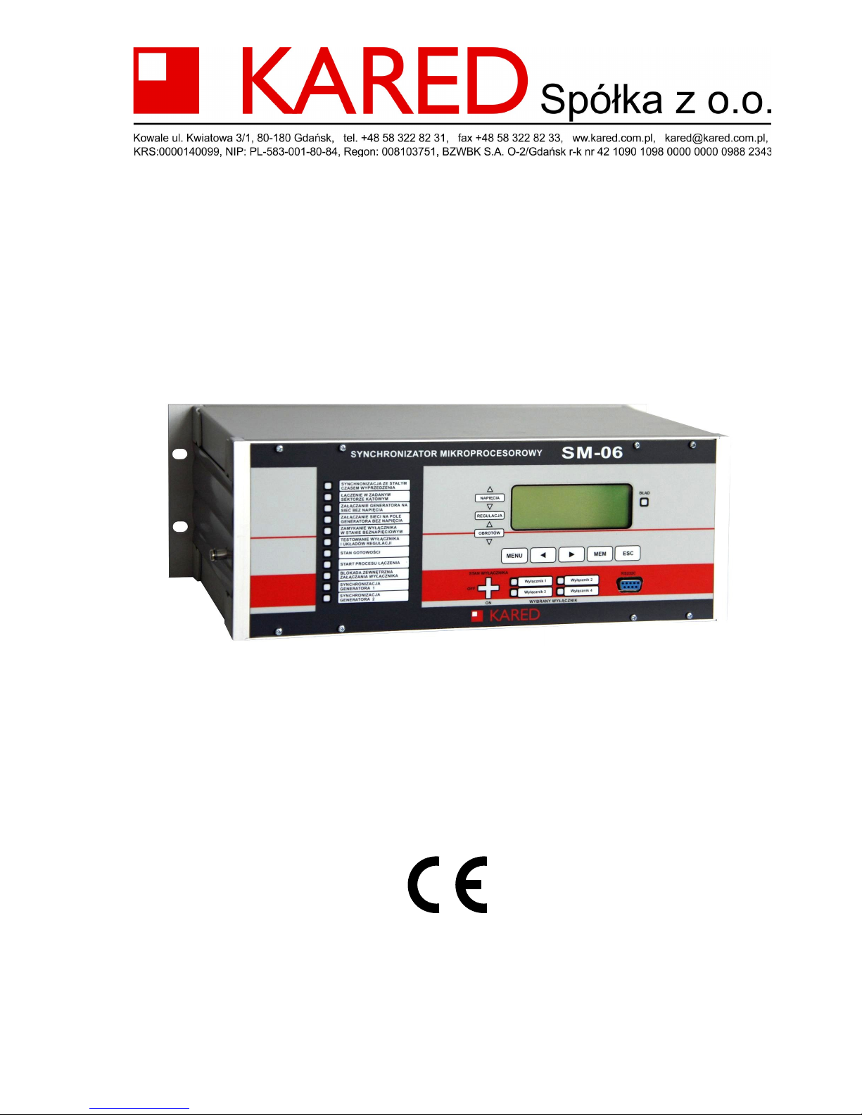
Synchronizer
SM-06
Instruction Manual
(version 4.2)
Copyright 2004-2017 by PUP Kared. All rights reserved.
This instruction manual may be reproduced and distributed in its entirety only.

PUP KARED Sp. o.o. reserves the right to make changes in our products consisting in ad -
vancement of their technical features. These changes can’t always be updated and taken
into consideration in the documentation.
Brand and product names mentioned herein are trademarks or registered trademarks be-
longing properly to their respective owners.
Manufacturer:
PUP KARED Sp. z o.o
ul. Kwiatowa 3/1
80-180 Gdańsk – Kowale
Phone +48 58 322 82 31
+48 58 324 86 45
Mobile phone +48 602 152 740
Fax +48 58 322 82 33
+48 58 324 86 46
E-mail kared@kared.com.pl
Internet http://www.kared.com.pl/
Copyright 2004-2017 by PUP Kared. All rights reserved.
This instruction manual may be reproduced and distributed in its entirety only.

IMPORTANCE OF INSTRUCTION MANUAL
In the event of doubt regarding the correct interpretation of the manual, please be
sure to ask manufacturer for explanation.
We will be grateful for any suggestions, opinions and criticisms of users and we kindly ask
you to transfer them in oral or written maner. This will help us make the instructions even
easier in use and take into account the wishes and requirements of users.
The device, to which this instruction manual is attached, includes impossible to
eliminate, potential threat to people and material values. Therefore, any person working
on the device or performing any activities related to the handling and preservation of the
device, must first be trained and know the potential danger. This requires careful reading,
understanding and compliance with the instruction manual, in particular the safety
instructions.

TABLE OF CONTENTS
IMPORTANCE OF INSTRUCTION MANUAL.......................................................................3
INFORMATION ON COMPLIANCE......................................................................................6
1. Device application..............................................................................................................7
1.1. Automatic synchronization with a constant lead time (SYN) ...................................7
1.2. Switching on separate objects in a given angle of incompatibility phase sector
(ZSK)..................................................................................................................................7
1.3. Switching on the generator switch on the mains without voltage (SBN).................7
1.4. Switching on the mains voltage on not-powered generator field (GBN)....................8
1.5. Switching on the switch with the absence of main and generator voltages (SGBN).8
1.6. The reviewing and modifying of the settings and measurements of some object pa-
rameters (TEST)................................................................................................................8
2. Safety rules........................................................................................................................8
3. Technical description and device operation....................................................................11
3.1. General description..................................................................................................11
3.2. Housing.....................................................................................................................11
3.3. The synoptic board...................................................................................................14
3.4. Signalling of errors....................................................................................................15
3.4.1. External errors...................................................................................................15
3.4.2. Internal errors....................................................................................................15
3.5. Operation description...............................................................................................15
3.5.1. Introduction - definitions and designations.......................................................15
3.5.2. Operating mode selection.................................................................................17
3.5.3. Starting and shutting down................................................................................17
3.5.4. Emergency discontinuation...............................................................................18
3.5.5. Operating modes...............................................................................................19
3.5.5.1. Automatic synchronization with a continous lead time ( SYN mode).......19
3.5.5.1.1. Voltage regulation...................................................................................21
3.5.5.1.2. Adjustment of the generator's rotational speed.....................................21
3.5.5.1.3. Prevention against not in-phase synchronous operation.......................22
3.5.5.1.4. Circuit breaker activation........................................................................22
3.5.5.2. Switching on separate objects in a set sector of phaze incompatibility
angle ( ZSK mode)..................................................................................................24

3.5.5.3. Closing the switch during voltage failure from one or both sides of the
circuit breaker (modes: SBN, GBN i SGBN)...........................................................26
3.5.5.4. Reviewing and modifying of settings and measurements of some object
parameters ( TEST mode)....................................................................................29
3.5.5.4.1. Settings...................................................................................................30
3.5.5.4.2. Network address.....................................................................................34
3.5.5.4.3. The measurement of tw time..................................................................35
3.5.5.4.4. Measurement of fi angle.........................................................................36
3.5.5.4.5. Measurement of C coefficient................................................................37
4. Technical data..................................................................................................................39
5. Data on completeness.....................................................................................................44
6. Installation and Commissioning.......................................................................................44
7. Monitoring the synchronization process..........................................................................45
7.1. Synchronization panel TS-10...................................................................................45
7.2. Visualization of synchronization process on a computer monitor............................47
7.3. Communication with the superior control system and control.................................47
7.3.1. Information available only during the correct operation of synchronizer..........48
7.3.2. Information also available in certain states of damage....................................54
8. Operation.........................................................................................................................55
8.1. Periodic checks........................................................................................................55
8.2. Troubleshooting........................................................................................................55
9. Transport and Storage.....................................................................................................55
10. Disposal.........................................................................................................................56
11. Warranty and Service....................................................................................................56
12. Ordering Guide..............................................................................................................57

INFORMATION ON COMPLIANCE
The device which is the subject of this manual is designed for use in industrial
environment. With the development and production of this device, such standards are
applied, which fulfillenes provide realization of assumed rules and safety measures, under
the condition that the user respects specified further guidelines for installation and
commissioning as well as the operation driving.
This device is a Class A. In a domestic environment it may cause radio
frequency interference. In such cases, the user can be requested for the
application of appropriate remedies.
This device is compatible with the provisions of EU directives:
• Low Voltage 73/23/EEC – introduced by the Regulation of the Minister of Economy,
Labour and Social Policy of 12.03.2003 (Journal of Laws No. 49, item 414)
• Electromagnetic Compatibility (EMC) 89/336/EEC – implemented by the Regulation
of the Minister of Infrastructure of 04.02.2003 (Journal of Laws No. 90 item 848).
Compliance with the directives has been confirmed by tests performed in independent
from manufacturer measurement and research laboratories.
Synchronizers SM-06 meet the essential requirements set out in Directives Low Voltage
and Electromagnetic Compatibility through compliance with the following standards:
The standard harmonized with Directive 73/23/EEC
• PN-EN 61010-1:2004 Safety requirements for electrical equipment for measure-
ment, control and laboratory units. General requirements.
The standards harmonized with Directive 89/336/EEC
• PN-EN 61000-6-2:2002 Electromagnetic Compatibility (EMC) – part 6-2: General
standards – Immunity for industrial environments.
• PN-EN 61000-6-4:2002 Electromagnetic Compatibility (EMC) – part 6-4: General
standards – Emission standards for industrial environments.

1. Device application
Microprocessor Automatic Synchronizer SM-06 is designed to automatically connect of
AC power facilities for parallel operation. It performs the following types of connections
(can operate in the following modes):
1.1. Automatic synchronization with a constant lead time (SYN)
After the power is turned on, synchronizer measures the the mains and generator voltage
and control signals on binary inputs. The measured value of the voltage and frequency
difference compares to the set limit values, and after signal "Start" generates regulatory
pulses, that reduce these differences to the set limit values. After the "alignment" of
voltages and frequencies generates switching the switch with a constant lead time. When
correctly executed connection it is discontinued.
Synchronizer is discontinued even if there are circumstances which prevent the
synchronization. Such discontinuation is an emergency discontinuation and causes
various alarms.
In the synchronizer relay signaling an error is activated and the display shows the
message indicating the reason for emergency discontinuation.
1.2. Switching on separate objects in a given angle of incompatibility phase sector (ZSK)
ZSK mode is used to connect the objects, when the synchronizer has no effect on the
voltage and frequency of connected objects, if the certain specified in the settings
connection conditions are fulfilled. When a signal "Start” was given, synchronizer will
generate the shutdown pulse of switch only, when the voltage difference, phase difference
and phase drift within the set time limit will not exceed the set limit values.
1.3. Switching on the generator switch on the mains without voltage (SBN)
SBN mode is used to close the breaker by a synchronizer, when the voltage and
frequency of the generator have the required values and mains rails are not powered.
When a signal "Start” was given, the synchronizer checks the voltages on both sides of

the switch and compares them to the set connecting conditions, which are the residual
voltage on the network rails and the voltage parameters on generator rails. If these values
fall within the preset range, generates a pulse closing switch. Checking the residual
voltage is designed to detect whether the network rails are not shorted.
1.4. Switching on the mains voltage on not-powered generator field (GBN)
GBN mode is used for switching the mains voltage on the not-powered mains of generator
own needs, using the synchronizer. When a signal "Start” was given, the synchronizer
checks the voltages on both sides of the switch and compare them to the set connecting
conditions, which are the voltage parameters on the mains rails and the residual voltage
on generator rails. If these values fall within the preset range, generates a pulse for circuit
breaker clousure. Checking the residual voltage is designed to detect whether the mains
rails are not shorted.
1.5. Switching on the switch with the absence of main and generator voltages
(SGBN)
SGBN mode is cused to the controlled by the the synchronizer circuit breaker clousure
when on its two sides is no power supply. Once a signal "Start" is given, the synchronizer
checks the voltage on both sides of the circuit breaker and compares it to the set
connecting conditions, which are the residual voltage on the mains rails and the residual
voltage on the generator rails. If these values fall within the preset range, generates
a pulse for circuit breaker clousure. Checking the residual voltage is designed to detect
whether the mains rails are not shorted.
1.6. The reviewing and modifying of the settings and measurements of some object parameters (TEST)
TEST mode is used to review and modify the settings of synchronizer and measurement
of certain parameters of the synchronized object, among others the circuit breaker closing
time.

2. Safety rules
The information contained in this section are intended to familiarize the user with the
proper installation and operation of the device. It is assumed that the installing, activating
and operating personnel of this device is properly qualified and is aware of the potential
dangers associated with the operation on the electrical equipment.
The device complies with applicable regulations and standards in terms of safety. In its
design particular attention to the safety of users was payed.
Device installation
The device should be installed on a place that provides appropriate environmental
conditions specified in the technical data. The device should be properly secured and
protected from mechanical damage and from accidental access of unauthorized persons.
The synchronizer is designed for panel or back panel mounting (depending on housing
version) in indoor switchgears. The synchronizer should be connected according to the
wiring diagram. External connections are connected by detachable spring connectors of
WAGO company. For connections of synchronizer it is recommended to use conductors
of LY type with section diameter 0,5÷1,5 mm2.
The synchronizer SM 06 is executed in first protection class and must be connected to the
protective conductor of the system to appropriately labeled terminal on the housing.
Commissioning
When you have installed the synchronizer its start-up in accordance with generally
accepted principles concerning protection devices, automation and control is to be carried
out.
Insulation test may cause a charge of the diffuse capacity to the dangerous voltage. After
each part of the test these capacities have to be discharged.
Operation of device
The device should work under the conditions specified in the technical data.
Personnnel operating the machine should be authorized and acquainted with the
instruction manual.

Removing the cover
Before performing any work with the necessity of housing removal, you must disconnect
all power supply and measurement voltages and then disconnect synchronizer from the
external circuits by dislodge all plugs.
Components used are sensitive to electrostatic discharge, thus device opening without the
proper antistatic equipment, can cause its damage.
Operation
After installing the device does not require additional service beyond the periodic checks
required by the relevant regulations. If you find any foult, please contact the manufacturer.
The manufacturer provides maintenance and post warranty services.
Warranty terms are specified in the Warranty Card.
Modifications and changes
Due to safety, any modifications and changes in functionality, covered by this manual are
not allowed. Device modifications to which the manufacturer does not give written
permission cause loss of any liability claims against the PUP KARED Sp. z o.o. Company.
Replacement of parts and components incorporated in the device from other
manufacturers than those used may affect the safety of its users and cause device
malfunctions.
PUP KARED Sp. z o.o. Company is not responsible for damages caused by use of
improper components and assemblies.
Disruptions
The possible disturbances observed in operation and other damage should be
immediately passed to the competent person.
Repairs may only be performed by qualified specialists.
Rating and information plates, stickers
Always observe the instructions given in the form of descriptions on the device,
information signs and labels, and keep them in a condition for good readability. Plates and
stickers that have been damaged or become illegible, should be replaced.

Fig 2.1. Sample of name plate
Nazwa:
PUP KARED Sp. z o.o.
ul. Kwiatowa 3/1, 80-180 Kowale
Rok prod.:
Zasilanie:
220VDC / 10W
Typ:
Nr fabr.:
SYNCHRONIZATOR
SM-06B-xxxxx-x-x
2016
250

3. Technical description and device operation
3.1. General description
Synchronizer SM-06 was built based on the microprocessor technology. Components of
the device are placed in APRA 63T housing in the panel embodiment or in 19-or 12-inch
rack Euro 3U production of RADMOR S.A. (back panel mounting execution).
Mains measuring voltages and object synchronized voltages (alternating with a nominal
value 100 V RMS) and binary signals (boosted by the DC voltage of value 220, 110 or
24 VDC, depending on the version of the device) are supplied: the type of connection, lock
off, start and switches states selection, on the basis of which, synchronizer states
conditions for the operation and automatically implements the selected type of connection.
The synchronizer is adapted for operation with a mains frequency of 50 Hz.
On the front panel (Synoptic Board or in brief TS) light emitting diodes are placed (LED)
and liquid crystal display (LCD), which indicate the operating mode and allow the process
of linking tracking. Faulty connections of external circuits, defects or malfunctions are
indicated by displaying the appropriate voice written messages on TS and by stimulating
internal error signals relay.
On Client’s request synchronizer SM-06 can be equipped with:
• additional synoptic board located on the control panel in the control room (TS-10)
connected to the device using the optical fiber cable, or with,
• additional communication interface RS 485 used by the host system,
• a program that allows the observation of the synchronization process on the PC
monitor, ie. so called "Virtual Synchronization Column”.
3.2. Housing
Synchronizers SM-06 are manufactured in three housing versions and are respectively
indicated by a version number: 1, 2 or 3.
• Version 1 – panel mounting housing Profi Set 63T of APRA company, designed for
mounting on the relay board in the switchboard, or inside the cabinet

• Version 2 – back panel mounting housing (cassette Euro 12” 3U) width 49T,
designed for installation on the board in the control room or on the switchgear
elevation,
• Version 3 – back panel mounting housing (cassette Euro 19” 3U) width 84T
designed for installation in a typical cabinet adapted for mounting 19-inch cassettes.
There are possible also other unusual versions of housings agreed with the manufacturer.
Typical versions of housing shown in Fig. 3.1, 3.2 and 3.3
Fig. 3.1 Version 1: Panel mounted housing Profi Set 63T of APRA company
Legend:
Widok od frontu – Front view
Zacisk PE – PE terminal

Fig. 3.2 Version 2: Back panel mounting housing with a width 49T
Legend:
Zacisk PE – PE terminal
Fig. 3.3 Version 3: Back panel mounting housing housing with a width 84T
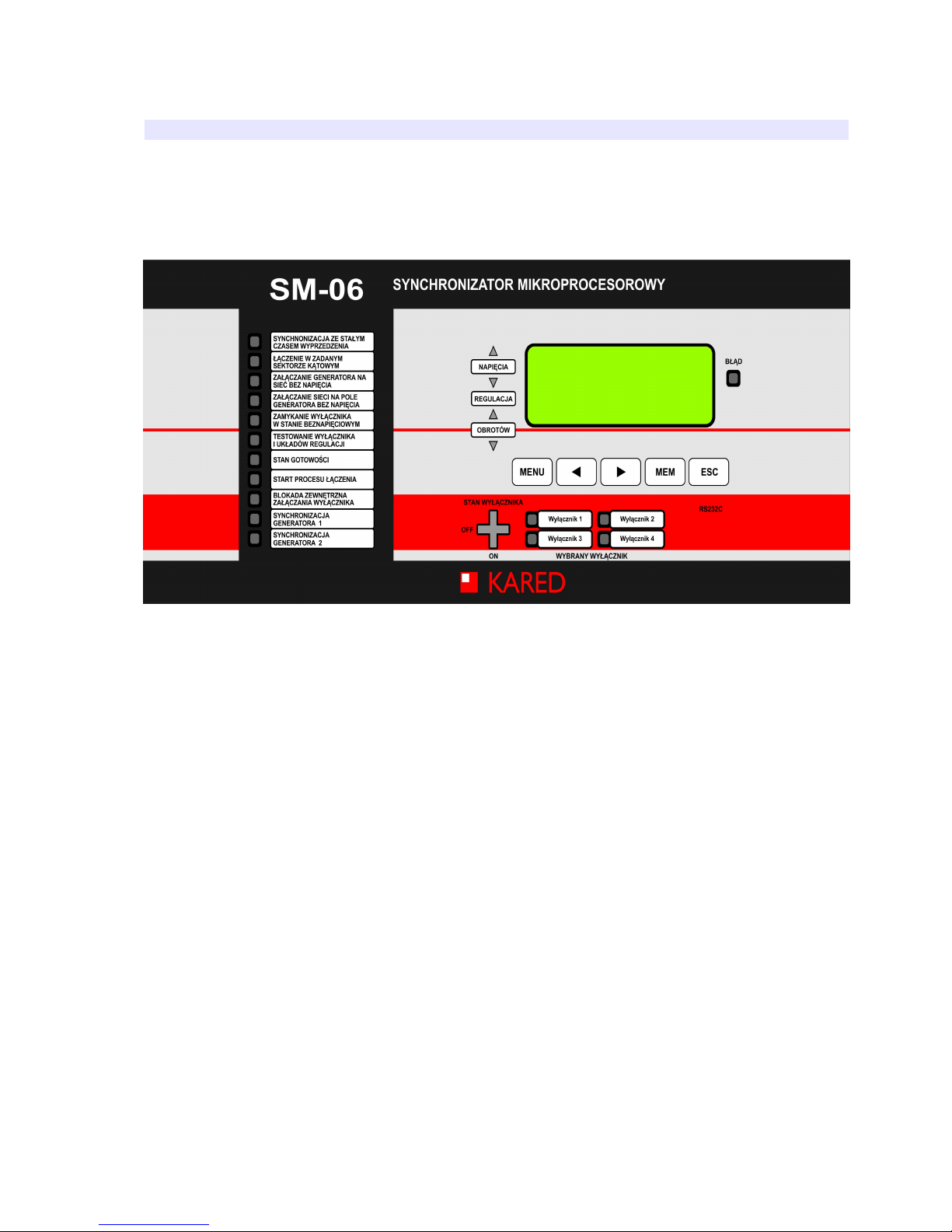
3.3. The synoptic board
Synchronizer SM-06 is equipped with a synoptic board, located on the front of the device
and especially facilitating the process of automatic synchronization at the first startup.
Fig. 3.4 View of the synchronizer SM-06B front panel
On the left side of the board the light emitting diodes (LEDs) are provided, to indicate
among others the selected operating mode, and on the right side: liquid crystal display
(LCD), keys (keyboard) and LEDs indicating the selected time of the switch closing. In the
lower right corner of the synoptic board socket RS 232C port for connecting a portable PC
is placed.
To the right from the LCD, the LED's indicating error are placed.
In the central part of the synoptic board under the inscription REGULATION, with
inscriptions VOLTAGES and ROTATIONS, illuminated arrows in tact to generate the
synchronizing pulses that affect the voltage regulators and the angular velocity of the
turbine set are placed. Arrows directed upwards are illuminated, when signals increasing
voltage and frequency are generated. Analogously arrows pointing downward, when the
signals lowering voltage and frequency are generated.

The status of the circuit breaker depict a cross-shaped lamps. Beam of the cross
illuminated in green (OFF) indicates that the circuit breaker is open, illuminated in red
(ON) that it is closed.
3.4. Signalling of errors
3.4.1. External errors
External errors are indicated by a corresponding written messages on the synchronizer's
LCD display. They include the damages or errors that occur outside the synchronizer, due
to lack of appropriate configuration of input signals (eg. broken cable, defective terminal,
etc.) or excess of signals (eg. short circuits). These errors cause the emergency
discountinuation of synchronizer and the detected terror signalling.
3.4.2. Internal errors
Internal errors can occur due to infringements of work of synchronizer. Which are
indicated in the form of digital code. In the event of an internal error, note its code, turn off
the power of synchronizer and turn it on again. If after restarting the same error will occur,
It is absolutely necessary to call the sernice, because it may indicate a internal damage of
synchronizer.
3.5. Operation description
This section describes detailing operation of SM-06 from device commissioning, handling
of irregularities, disabling and finally the implementation of the selected operating mode.
3.5.1. Introduction - definitions and designations
Synchronizer power supply

1.
Up –
the auxiliary voltage of the nominal value 220 VDC or 110 VDC or 24 V DC
(depending on the version of synchronizer) for providing power to
synchronizer. It is used also by an internal diode and Uv clamp to stimulate
inputs of operation mode selection and inputs for devices control. The
rated Up voltage, is also the rated voltage applied to all binary inputs.
Analog input signals
1.
Us –
mains voltage with a nominal value 100 V RMS and frequency 50 Hz from
the voltage relay,
2.
Ug –
voltage of object connected to the mains with a nominal value 100 V RMS
from the voltage relay (eg. generating set or power subsystem).
Discrete input signals (voltage, the Up value)
A. Operation mode selection signals:
1.
SYN –
automatic SYNchronization with a lead fixed time,
2.
ZSK –
Enabling of dedicated facilities in the set sector of non-compliance
phase angle,
3.
SBN –
Enabling the generator switch on a Mains Without Voltage,
4.
GBN –
Activation of mains voltage on not powered generator field (Generator
Bez Napięcia - Generator Without Voltage),
5.
SGBN –
Enabling the circuit breaker in the absence of mains and generator
voltages (Sieć i Generator Bez Napięcia – Mains and Generator Wi-
thout Voltage),
6.
TEST –
Reviewing and modification of settings and measurements of some
parameters of object.
B. Control signals:
1.
START -
START of the connecting process,
2.
BLKZ -
External interlock of signal activating a circuit breaker.
C. Switch status and selection circuit breaker settings signals:

1.
W1o –
circuit breaker W1 opened, settings of the circuit breaker W1
2.
W1z –
circuit breaker W1 closed,
3.
W2o –
circuit breaker W2 opened, settings of the circuit breaker W2
4.
W2z –
circuit breaker W2 closed,
Discrete output signals (relay contacts)
1.
ZW –
pulse switching circuit breaker on,
2.
BL –
error signaling,
3.
OG –
pulse signal increasing rotations of generator,
4.
OD –
pulse signal reducing rotations of generator,
5.
NG –
pulse signal increasing voltage of generator,
6.
ND –
pulse signal reducing voltage of generator.
3.5.2. Operating mode selection
You can select one of the following operating modes:
1.
SYN –
automatic SYNchronization with a lead fixed time
2.
ZSK –
Connecting of dedicated objects (eg. connecting of mains) in the set
sector of non-compliance phase angle, working quasi synchronously
3.
SBN –
Enabling the generator switch on a Mains Without Voltage
4.
GBN –
Activation of mains voltage on not powered generator field (Generator
Bez Napięcia - Generator Without Voltage)
5.
SGBN
–
Enabling the circuit breaker in the absence of mains and generator
voltages Mains and Generator Without Voltage
6.
TEST –
Reviewing and modification of settings and measurements of selected
parameters
Setting the operating mode takes place immediately after turning the power and device
auto testing. Then it is checked on which of the six inputs of operation mode selection is
the voltage. Corresponding to this input mode is selected and the subsequent change is
impossible, until the synchronizer power is turned off. If the voltage is on more than one of
the six inputs of operating mode selection, or is not on any, the device enters the emer -

gency withdrawal state. The state of voltages on the above inputs can not be varied for all
modes except for TEST, until the moment of voltage supply at the START input; and for
TEST mode until the power supply is turned off. Type of the selected mode is confirmed
by the illumination of the appropriate LED, on the left TS side.
3.5.3. Starting and shutting down
Synchronizer is started by switching the supply voltage Up with WZ circuit breaker (Fig.
4.1, 4.2). After powering synchronizer is performing the auto test, waits the time specified
by the setpoint Td (table 3.1, I.no. 46), and then checks the correctness of of input signals
(Td setpoint does not include the auto testing time, which is approx.1,8s). Correct status of
input signals occurs when following conditions are met simultaneously:
• Uv voltage– derived from synchronizer - is present on one and only one input of:
SYN, ZSK, SBN, GBN, SGBN, TEST,
• Uv voltage is not present at the START input,
• Uw voltage (.)is present on one and only one input of: W1o – W2o,
• Uw voltage (.) is not present on inputs W1z – W2z.
Where:
Uv –
constant voltage from the output of synchronizer power supply Z14
package, with a nominal Up value,
Uw(.) – constant voltage with a nominal Up value; dot in parentheses (.) – is the
number of the selected circuit breaker.
If the synchronizer detects an abnormal state of input signals, it proceeds to emergency
discontinuation status, but if the configuration of the of input signals is correct, to waiting
status (except for the TEST mode, as well as ZSK, where the standby staus is preceded
by drift measurement status). Standby staus continues until the appearance of START
signal (+Uv signal on START input), stimulating the set type of connection. When correctly
executed connection the synchronizer passes to discontinuation after switching status.
The synchronizer can be turned off at any time by turning off the power supply Up voltage
with the WZ circuit breaker.
The synchronizer uses the control system of UP supply voltage. If the value of this voltage
drops below Upmin (value is given in the technical data), device will enter the state of
emergency discontinuation. This is intended to prevent misinterpretation of the binary

input states, also supplied from Up voltage, in the event of voltage decrease below the
switching threshold of these inputs.
3.5.4. Emergency discontinuation
Emergency discontinuation takes place when synchronizer detects a bug that prevents the
proper execution of set connection.
Emergency discontinuation causes:
1. Error signalling – short circuit +BL from BL (relay contacts),
2. Display the error message on the LCD display,
3. Lighting of LED signaling an error.
If the reason for discontinuation is invalid status of the inputs, on the display after
DISCONTINUATION inscription code 15 is displayed– incorrect configuration of the input
binary signals after powering (see item 7.3.1 pag. 52).
OD S T AWI E N I E 1 5
Ug = 1 0 0 , 2 % F g = 5 0 , 0 0 H z
Us = 1 0 0 , 2 % F s = 5 0 , 0 0 Hz
f i g - f i s = 1 2 , 1 1 º
Fig. 3.5
Legend:
ODSTAWIENIE – DISCONTINUATION
indicate that the measured angle is the actual phase-angle measuring voltages
Ug and Us applied to the synchronizer inputs, (without correction of constant phase shift
angle).

3.5.5. Operating modes
In this section will be discussed the performance of synchronizer individual operating
modes.
3.5.5.1. Automatic synchronization with a continous lead time ( SYN mode)
In order to connect alternating current objects for parallel operation with the set lead time
(synchronization) it shouldt be:
1. Selector switch of the connection type (WRL, Fig. 4.1, 4.2) set in the SYN
position.
2. Close the correct key of switch selection (WW1 or WW2, Fig. 4.1, 4.2).
3. Turn on the synchronizer power.
After powering synchronizer starts with auto testing and validation of input signals. After
auto testing it goes to waiting status, unless earlier detects an error, then to the status of
emergency discontinuation.
In the waiting status (Fig. 3.6) there are displayed the current effective values of the
voltage measurements Us and Ug in % nominal value of 100V, and their frequency Fs
and Fg. In the last line the phase difference is displayed dfi = dfg – dfs and the status of
the signals on the two inputs: START - S and BLKZ – B. „0” - means inactive status of
input (no voltage), „1” – active status (it is the voltage + Uv).
In addition, the waiting status is signaled by lighting of the yellow LED: STANDBY
STATUS.
S Y N W 1 OC Z E K .
U g = 1 0 5 , 4 % F g = 5 0 , 5 6 H z
U s = 1 0 0 , 1 % F s = 4 9 , 99H z
d f i = - 1 3 º S = 0 B= 0
Fig. 3.6
In the waiting state the synchronizer does not send any signals and stays there until
a voltage appears at the START input. The voltage at the START input, does not have to
be kept, only you need a pulse.
 Loading...