

Page 1
RBS 6000
Deutsch 3
English 12
Français 21
Italiano 30
Nederlands 39
Español 48
Suomi 57
Русский 66
Magyar 76
Slovenščina 85
59516800 01/19
Page 2

2
Page 3
Lesen Sie vor der ersten Benut-
zung Ihres Gerätes diese Originalbetriebsanleitung, handeln Sie danach
und bewahren Sie diese für späteren Gebrauch oder für Nachbesitzer auf.
Inhaltsverzeichnis
Umweltschutz . . . . . . . . . . . DE . . 1
Symbole in der Betriebsanlei-
tung. . . . . . . . . . . . . . . . . . . DE . . 1
Sicherheitshinweise . . . . . . DE . . 1
Bedienelemente . . . . . . . . . DE . . 3
Transport. . . . . . . . . . . . . . . DE . . 3
Erstinbetriebnahme. . . . . . . DE . . 3
Betrieb . . . . . . . . . . . . . . . . DE . . 5
Lagerung. . . . . . . . . . . . . . . DE . . 6
Wartung und Pflege . . . . . . DE . . 6
Störungshilfe. . . . . . . . . . . . DE . . 8
Technische Daten . . . . . . . . DE . . 8
Zubehör . . . . . . . . . . . . . . . DE . . 9
EU-Konformitätserklärung . DE . . 9
Garantie . . . . . . . . . . . . . . . DE . . 9
Ersatzteile . . . . . . . . . . . . . . DE . . 9
Umweltschutz
Die Verpackungsmaterialien
sind recyclebar. Bitte werfen
Sie die Verpackungen nicht in
den Hausmüll, sondern führen
Sie diese einer Wiederverwer-
tung zu.
Altgeräte enthalten wertvolle
recyclingfähige Materialien, die
einer Verwertung zugeführt
werden sollten. Batterien, Öl
und ähnliche Stoffe dürfen
nicht in die Umwelt gelangen.
Bitte entsorgen Sie Altgeräte
deshalb über geeignete Sam-
melsysteme.
Getriebeöl nicht in die Umwelt gelangen
lassen. Bitte Boden schützen und Altöl umweltgerecht entsorgen.
Mineralölhaltiges Abwasser nicht ins
Erdreich, Gewässer oder ohne Aufbereitung in die Kanalisation gelangen lassen.
Bitte örtlich geltende gesetzliche Bestimmungen und Abwassersatzungen beachten.
Hinweise zu Inhaltsstoffen (REACH)
Aktuelle Informationen zu Inhaltsstoffen finden Sie unter:
www.kaercher.de/REACH
Symbole in der
Betriebsanleitung
GEFAHR
Für eine unmittelbar drohende Gefahr, die
zu schweren Körperverletzungen oder zum
Tod führt.
몇 WARNUNG
Für eine möglicherweise gefährliche Situation, die zu schweren Körperverletzungen
oder zum Tod führen könnte.
VORSICHT
Für eine möglicherweise gefährliche Situation, die zu leichten Verletzungen oder zu
Sachschäden führen kann.
Sicherheitshinweise
Sicherheitshinweise
Allgemein
Um Gefahren für Personen, Tiere und Sachen zu vermeiden, lesen Sie bitte vor dem
ersten Betreiben der Anlage:
– die Betriebsanleitung
– alle Sicherheitshinweise
– die jeweiligen nationalen Vorschriften
des Gesetzgebers
– die Sicherheitshinweise, die den ver-
wendeten Reinigungsmitteln beigestellt
sind (i.d.R. auf dem Verpackungsetikett).
Für den Betrieb dieser Anlage gelten in der
Bundesrepublik Deutschland folgende Vorschriften und Richtlinien (beziehbar über
Carl Heymanns Verlag KG, Luxemburger
Straße 449, 50939 Köln):
– Unfallverhütungsvorschrift „Allgemeine
Vorschriften“ BGV A1
– Verordnung über Betriebssicherheit
(BetrSichV).
Vergewissern Sie sich:
– dass Sie selbst alle Hinweise verstan-
den haben
– dass alle Anwender der Anlage über die
Hinweise informiert sind und diese verstanden haben.
Diese Betriebsanleitung ist vom Betreiber
der Waschanlage unter Beachtung der örtlichen und personellen Gegebenheiten in
eine Betriebsanweisung umzusetzen. Die
Betriebsanweisung ist in geeigneter Weise
durch Auslegen oder Aushängen am Arbeitsplatz bekanntzumachen.
Fahrzeugwaschanlagen
Mit dem Betätigen, Überwachen, Pflegen,
Warten und Überprüfen von Fahrzeugwaschanlagen dürfen nur Personen beauftragt werden, die mit diesen Arbeiten und
mit der Betriebsanleitung vertraut und über
die mit der Anlage verbundenen Gefahren
belehrt worden sind.
Selbstbedienung
ei Selbstbedienungs-Fahrzeugwaschanlagen muss während der Betriebsbereitschaft eine Person erreichbar sein, die mit
der Anlage vertraut ist und im Störfall die
zur Vermeidung etwaiger Gefahren notwendigen Maßnahmen durchführen oder
veranlassen kann.
Für den Benutzer der Anlage müssen gut
sichtbare Hinweise über Bedienung und
bestimmungsgemäße Verwendung der Anlage am Waschplatz angebracht sein.
Instandhaltung
Instandhaltungsarbeiten dürfen grundsätzlich nur bei ausgeschalteter Anlage ausgeführt werden. Dabei ist der Hauptschalter
gegen Wiedereinschalten durch Unbefugte
zu sichern.
Gefahrenstoffe
Beim Umgang mit Reinigungsmittelkonzentraten, die gesundheitsschädliche Stoffe enthalten, sind Schutzmaßnahmen zu
treffen. Insbesondere sind Schutzbrille,
Schutzhandschuhe und Schutzkleidung zu
tragen und die dem Reinigungsmittel beigegebenen Merkblätter/Sicherheitsdatenblätter zu beachten.
Betreten der Fahrzeugwaschanlage
Unbefugten Personen ist das Betreten der
Fahrzeugwaschanlage zu verbieten. Auf
das Zutrittsverbot ist deutlich erkennbar
und dauerhaft hinzuweisen.
Rutschgefahr
In der Anlage besteht Rutschgefahr durch
Nässe auf dem Boden und auf Anlagenteilen. Bei Arbeiten an der Anlage umsichtig
bewegen und geeignetes Schuhwerk tragen. Waschkunden durch geeignete Beschilderung auf die Rutschgefahr
hinweisen.
Bedienung der Anlage
몇 WARNUNG
Um Gefahren durch falsche Bedienung zu
vermeiden, darf die Anlage nur von Personen bedient werden, die
– in deren Handhabung unterwiesen sind
– ihre Fähigkeiten zum Bedienen nach-
gewiesen haben
– ausdrücklich mit der Benutzung beauf-
tragt sind.
Die Betriebsanleitung muss jedem Bediener zugänglich sein. Nicht bedient werden
darf die Anlage von Personen unter 18 Jahren. Davon ausgenommen sind Auszubildende über 16 Jahren unter Aufsicht.
몇 WARNUNG
Stolpergefahr durch am Boden liegende
Gegenstände oder Zuleitungen.
Vor Inbetriebnahme der Anlage auf dem
Waschplatz liegende Gegenstände entfernen.
Bei Verwendung der Anlage mit Kabelschlepp am Boden muss auf sorgfältige
Nachführung der Zuleitungen geachtet
werden.
Bestimmungsgemäße Verwendung
Die RBS 6000 ist für die Bürstenwäsche
von Bussen und Transportern, Lkw, Lkw
mit Anhänger und Sattelzügen bestimmt.
Die Neigung der Seitenwände der Fahrzeuge muss kleiner als 10 Grad sein.
Die Anlage kann in einer Waschhalle oder
im Freien betrieben werden.
- 1
3DE
Page 4

Zur bestimmungsgemäßen Verwendung
gehören auch:
– das Beachten aller Hinweise in dieser
Betriebsanleitung und
– die Einhaltung der Inspektions- und
Wartungshinweise.
VORSICHT
Erhöhte Korrosionsgefahr durch Verwendung ungeeigneter Reinigungsmittel.
Folgende Reinigungsmittel dürfen nicht
von der Anlage verarbeitet werden:
– Reinigungsmittel die für die Reinigung
der Waschhalle bestimmt sind.
– Reinigungsmittel die zur äußeren Reini-
gung der Waschanlage bestimmt sind.
– Reinigungsmittel, die mit einem separa-
ten Gerät auf das Fahrzeug aufgebracht werden (z. B. Felgenreiniger).
– Mittel zur Abwasserbehandlung.
Nur von KÄRCHER freigegebene Reinigungsmittel verwenden.
Arbeitsplatz
Die Anlage wird mit beiden Händen am
Griff festgehalten und am Fahrzeug entlanggezogen. Dabei muss der jeweilige Sicherheitsschalter Bürste mit einer Hand
betätigt werden.
Sachwidrige Verwendung
VORSICHT
Beschädigungsgefahr! Die RBS 6000 ist
nur geeignet für die Reinigung von Fahrzeugen mit geraden glatten Seitenwänden,
deren Neigung kleiner als 10° ist.
Der Betreiber der Anlage haftet für alle
Schäden, die durch unsachgemäße Anwendungen entstehen, insbesondere
durch Reinigung von Fahrzeugen, die nicht
in dieser Anleitung beschrieben sind.
Gefahrenquellen
Allgemeine Gefahren
GEFAHR
Verletzungsgefahr durch wegfliegende Teile! Wegfliegende Bruchstücke oder Gegenstände können Personen oder Tiere
verletzen. Deshalb muss der Hallenboden
frei von lose herumliegenden Gegenständen sein.
Bei Wartungsarbeiten Schutzbrille tragen.
Explosionsgefahr
GEFAHR
Explosionsgefahr! Die Anlage darf nicht in
der Nähe von explosionsgefährdeten Räumen betrieben werden.Davon ausgenommen sind nur ausdrücklich dafür
vorgesehene und gekennzeichnete Anlagen.Als Reinigungsmittel dürfen keine explosiven, hochentzündlichen oder giftigen
Stoffe verwendet werden, wie z.B.:
– Benzin
– Heizöl und Dieselkraftstoff
– Lösungsmittel
– lösungsmittelhaltige Flüssigkeiten
– unverdünnte Säuren
– Aceton
Bei Unsicherheit Hersteller fragen.
Gehörschäden
Die von der Anlage ausgehenden Geräusche sind gefahrlos. Werden jedoch geräuschverstärkende Teile/Körper
abgestrahlt, kann eine Lärmgefährdung
eintreten. In diesem Fall Gehörschutz tragen.
Elektrische Gefahren
GEFAHR
Gefahr durch elektrischen Schlag.
– Elektrische Kabel, Steckverbindungen
und Klemmkästen nie mit nassen Händen anfassen.
– Elektrische Anschlussleitungen oder
Verlängerungskabel dürfen nicht durch
Überfahren, Quetschen, Zerren oder
ähnliches beschädigt werden. Kabel
vor Hitze, Öl und scharfen Kanten
schützen.
– Mit beweglichem Reinigungsgerät (z.B.
mit Hochdruckreinigern) darf der Wasserstrahl nie auf elektrische Geräte
oder Anlagen gerichtet werden.
– Alle stromführenden Teile im Arbeitsbe-
reich müssen strahlwassergeschützt
sein.
– Anlagen dürfen nur an ordnungsgemäß
geerdeten Stromquellen angeschlossen werden.
– Alle Arbeiten an elektrischen Teilen der
Anlage dürfen nur von einer Elektrofachkraft ausgeführt werden.
– Zubehörteile, die nicht direkt mit der An-
lage verbunden sind, müssen in den
Potentialausgleich eingebunden werden.
Gefahr durch gesundheitsgefährdende
Stoffe
GEFAHR
Die verwendeten Reinigungsmittel enthalten teilweise gesundheitsgefährdende
Stoffe, daher sind unbedingt die beigegebenen bzw. aufgedruckten Hinweise zu beachten.
Das von der Anlage abgegebene Wasser
nicht trinken! Durch beigemischte Reinigungsmittel besitzt es keine Trinkwasserqualität.
Wird zum Betrieb der Anlage aufbereitetes
Brauchwasser verwendet, müssen die Vorschriften zur Keimhemmung des Herstellers der Aufbereitungsanlage beachtet
werden.
Stoffe, wie sie nicht bei einer allgemein üblichen Außenreinigung von Fahrzeugen anfallen (wie z.B. Chemikalien,
Schwermetalle, Pestizide, radioaktive Stoffe, Fäkalien oder Seuchenstoffe) dürfen
nicht in die Waschanlage gelangen.
Gefahr durch Stromausfall
Ein unkontrolliertes Wiederanlaufen der
Anlage nach Stromausfall ist durch konstruktive Maßnahmen ausgeschlossen.
Die Bürste dreht sich nur bei Betätigung eines Sicherheitsschalters.
Umweltgefährdung durch Abwasser
Zur Abwasserentsorgung sind die örtlichen
Vorschriften zu beachten.
Instandhaltung und Überwachung
Um einen sicheren Betrieb der Anlage zu
gewährleisten und Gefahren bei Wartung,
Überwachung und Prüfung zu verhindern,
müssen die entsprechenden Anweisungen
eingehalten werden.
Instandhaltung
Wartungsarbeiten müssen durch eine
sachkundige Person zu regelmäßigen Zeitpunkten nach den Angaben des Herstellers
durchgeführt werden, dabei sind bestehende Bestimmungen und Sicherheitsanforderungen zu beachten. Arbeiten an der
Elektroanlage dürfen nur von einer Elektrofachkraft durchgeführt werden.
GEFAHR
Verletzungsgefahr. Die Anlage muss abgeschaltet und gegen unbeabsichtigtes und
unbefugtes Wiedereinschalten gesichert
sein, bevor Wartungs- und Instandhaltungsarbeiten durchgeführt werden.
Überwachung
Diese Waschanlage muss vor der ersten
Inbetriebnahme und danach mindestens
halbjährlich von einer sachkundigen Person auf ihren sicheren Zustand überprüft
werden.
Diese Überprüfung umfasst insbesondere:
– Sichtprüfung bezüglich äußerlich er-
kennbarem Verschleiß bzw. Beschädigung
– Funktionsprüfung
– Vollständigkeit und Wirksamkeit von Si-
cherheitseinrichtungen bei Selbstbedienungsanlagen täglich vor
Betriebsbeginn, bei überwachten Anlagen nach Bedarf, jedoch mindestens
einmal monatlich.
Originalteile verwenden
Verwenden Sie ausschließlich Originalteile
des Herstellers oder von ihm empfohlene
Teile, da sonst Gewährleistungsansprüche
erlöschen. Beachten Sie alle Sicherheitsund Anwendungshinweise, die diesen Teilen beigestellt sind. Dies betrifft:
– Ersatz- und Verschleißteile
– Zuberhörteile
– Betriebsstoffe
– Reinigungsmittel.
Not-Aus-Schalter
GEFAHR
Unfallgefahr durch defekte Sicherheitseinrichtungen! Die Anlage besitzt einen NotAus-Schalter und zwei „Sicherheitsschalter
Bürste“.
Sicherheitseinrichtungen müssen nach Bedarf, mindestens jedoch einmal monatlich,
auf ihr ordnungsgemäßes Funktionieren
überprüft werden!
4 DE
- 2
Page 5
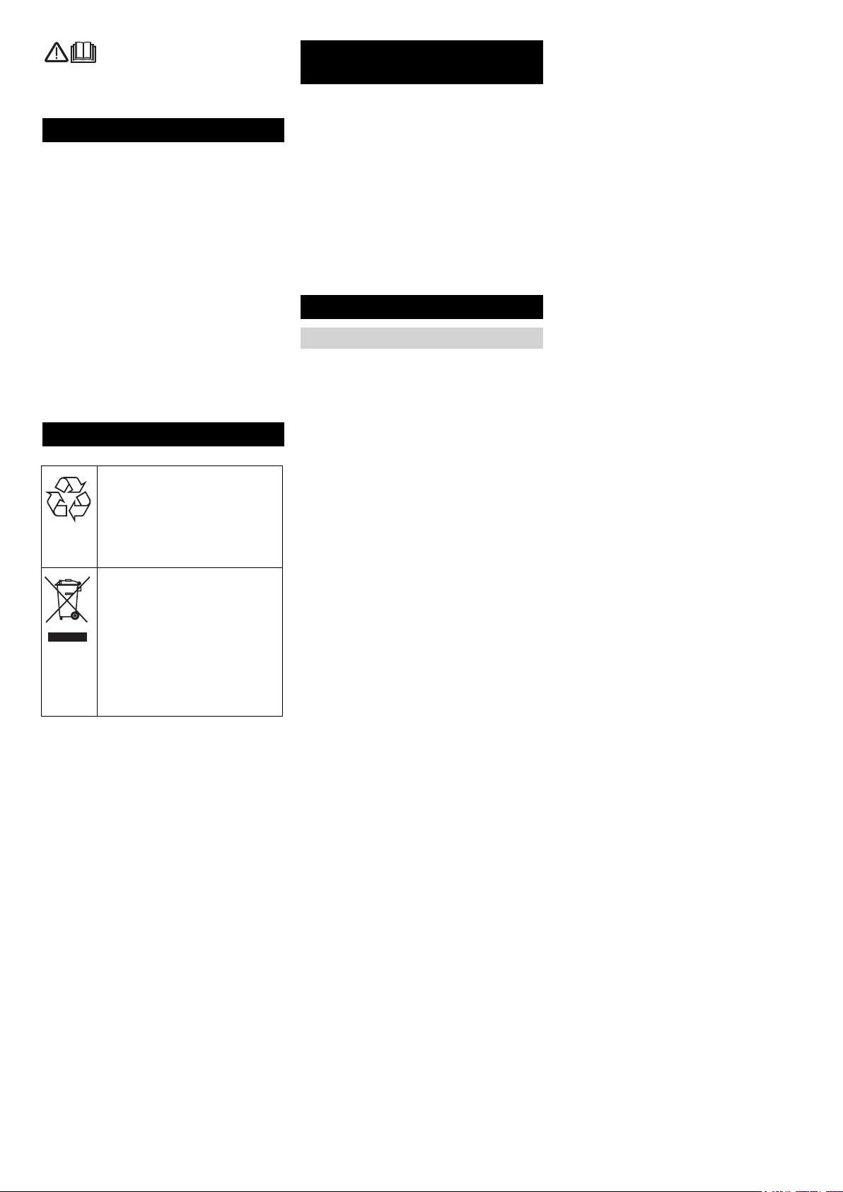
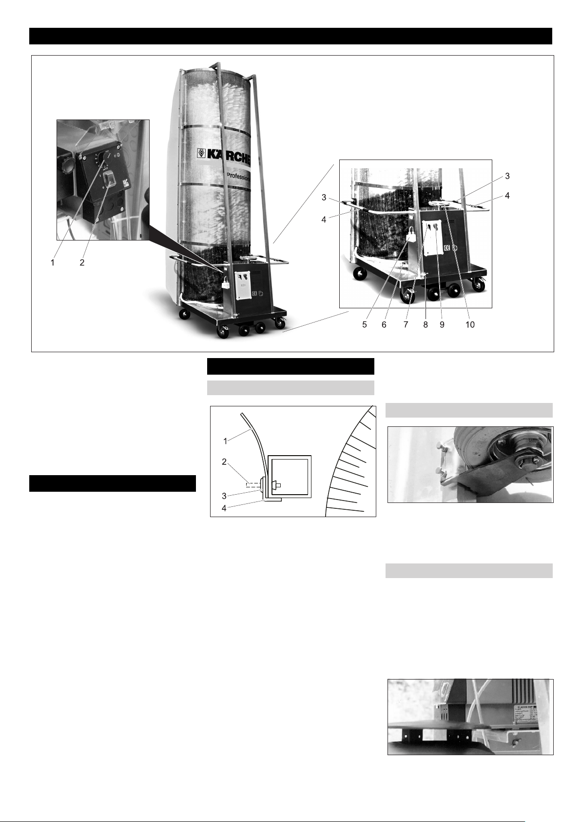
Bedienelemente
1 Drehknopf Dosierpumpe*
2 Schalter Dosierpumpe*
3 Handgriff
4 Sicherheitsschalter (Bürste)
5 Netzstecker
6 Absperrventile für Düsenrohre
7 Hauptschalter
8 Wasseranschluss
9 Not-Aus-Taster
10 Schrägstellkurbel
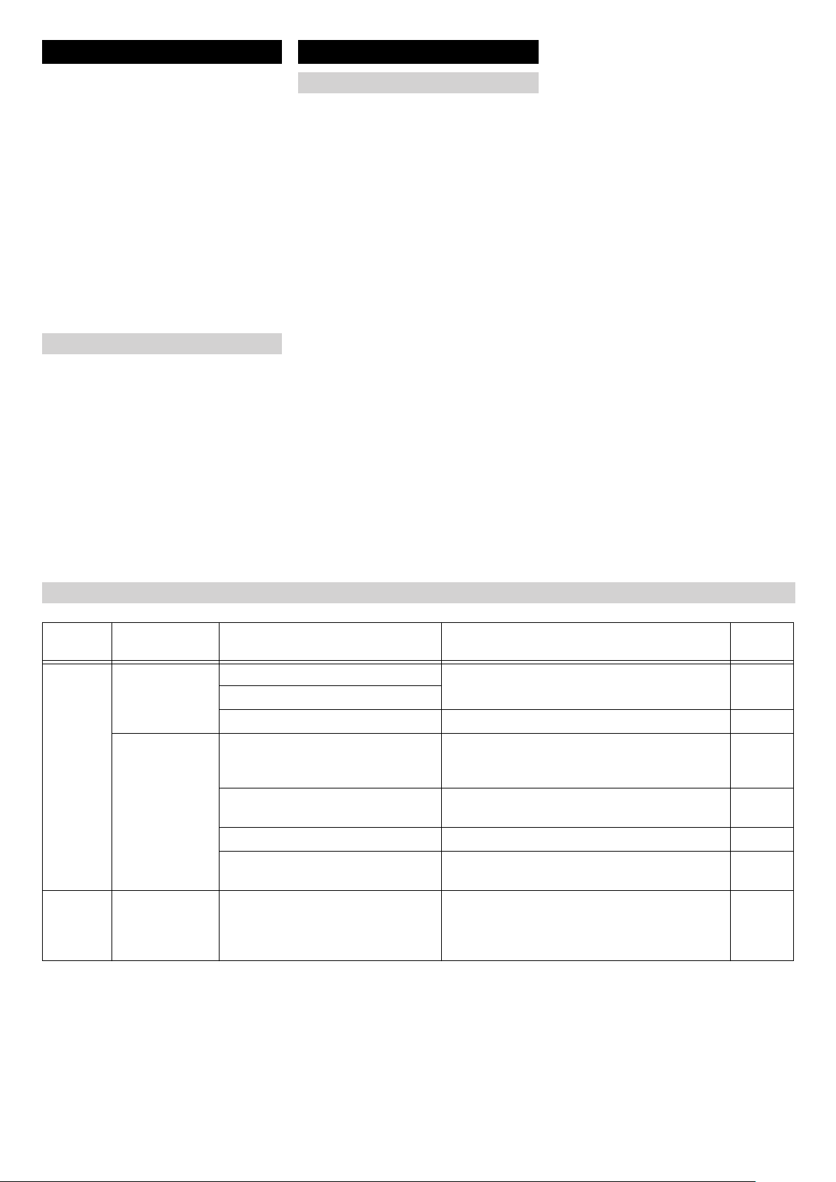
Transport
몇 WARNUNG
Verletzungs- und Beschädigungsgefahr!
Gewicht der Anlage beim Transport beachten.
Die Anlage kann liegend auf der Ladefläche eines LKW transportiert werden:
Distanzrollen entfernen.
Anlage mit zwei Personen auf die Bürs-
tenseite kippen.
Anlage auf die Ladefläche schieben.
Anlage gegen Verrutschen sichern.
Erstinbetriebnahme
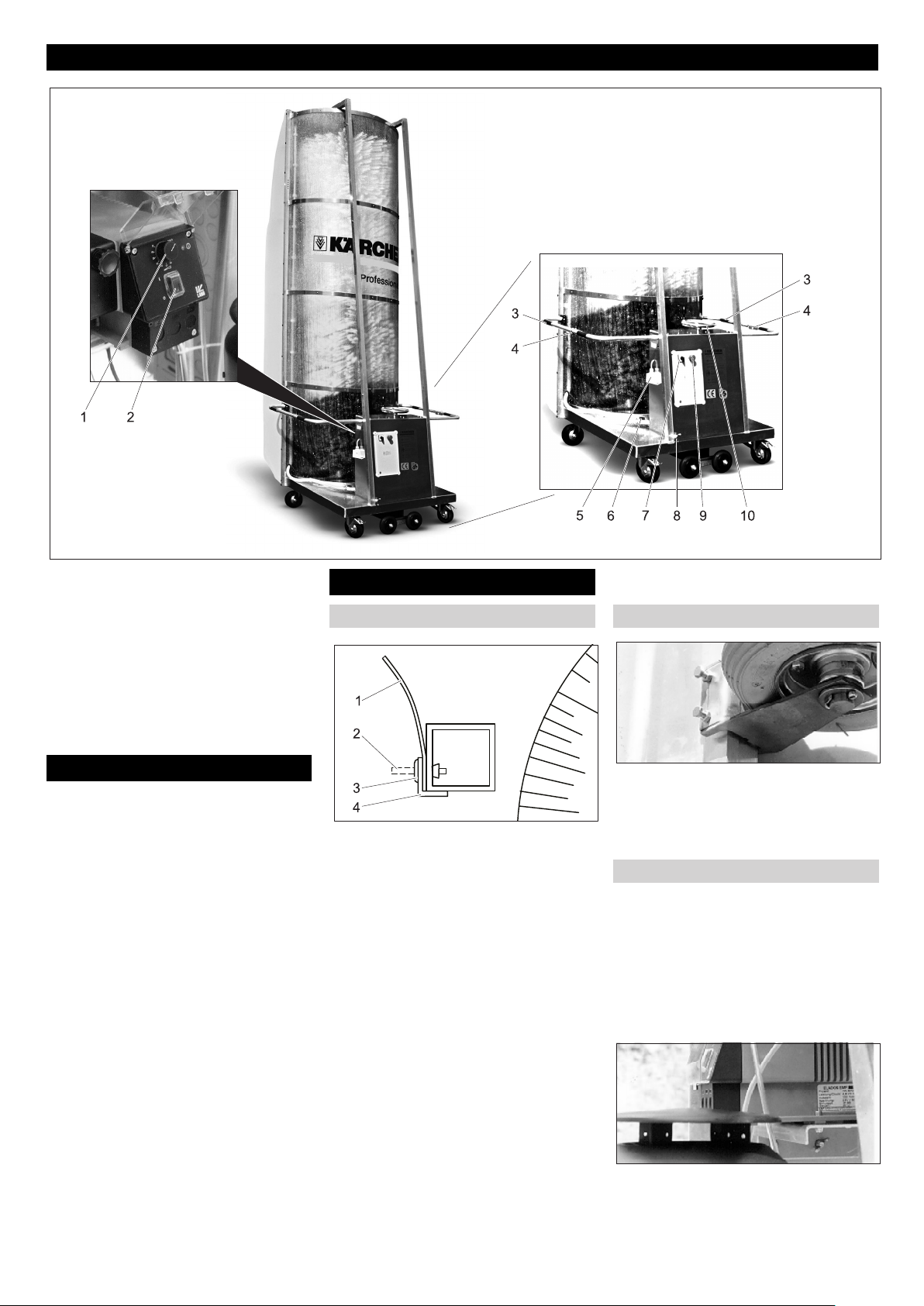
Spritzschutz anbringen Distanzrollen montieren
1 Spritzschutz
2 Stift
3 Spreizniet
4 Winkelprofil
Die beiden Winkelprofile sind zum Transport mit Spreiznieten am Gestell befestigt,
Einbaulage der Winkelprofile für die
Montage merken.
Stifte der Spreiznieten mit einem
Durchschlag nach innen schlagen.
Winkelprofile abnehmen.
Beiliegenden Spritzschutz ausrollen
und auf das Vierkantrohr legen.
Hinweis:
Die Spritzschutz-Streifen sind in der kurzen
Richtung gewölbt. Bei der Montage muss
diese Wölbung von der Bürste wegzeigen.
Winkelprofil wieder auflegen.
Spreizniete durch Winkelprofil, Spritz-
schutz und Vierkantrohr stecken und
fest eindrücken.
Stift der Spreizniete mit dem Hammer
einschlagen.
diesen Vorgang bei allen Bohrungen in
den Winkelprofilen wiederholen.
Beide beigelegten Distanzrollen am
Gestell der Anlage befestigen.
Höhe entsprechend den zu waschen-
den Fahrzeugen wählen.
Kontermuttern festziehen.
Dosierpumpe anbringen
Bei folgenden Anlagen ist keine Dosierpumpe im Standard-Lieferumfang enthalten:
– 1.286-235.0
– 1.286-245.0
– 1.286-345.0
– 1.286-435.0
– 1.286-445.0
Dosierpumpe mit beiliegendem Monta-
gematerial am Gestell der Anlage befestigen.
- 3
5DE
Page 6
Waschplatz
Die Anlage kann in einer Waschhalle oder
im Freien betrieben werden.
Elektroanschluss
400V, 3~, P,
N, 50 Hz
Kabeltyp Länge
5 x 2,5 H07RN-F
max. 100 m
Kabel der Dosierpumpe einstecken.
Reinigungsmittelkanister füllen und auf
die Grundplatte der Anlage stellen.
Saugschlauch der Dosierpumpe mit
Saugfilter in Kanister stecken und Deckel aufschrauben.
Schlauch vom Dosierpumpenausgang
auf Verschraubung am Wasserverteiler
stecken und Überwurfmutter festziehen.
Handgriff einstellen
Die Handgriffe können in zwei Stellungen
befestigt werden.
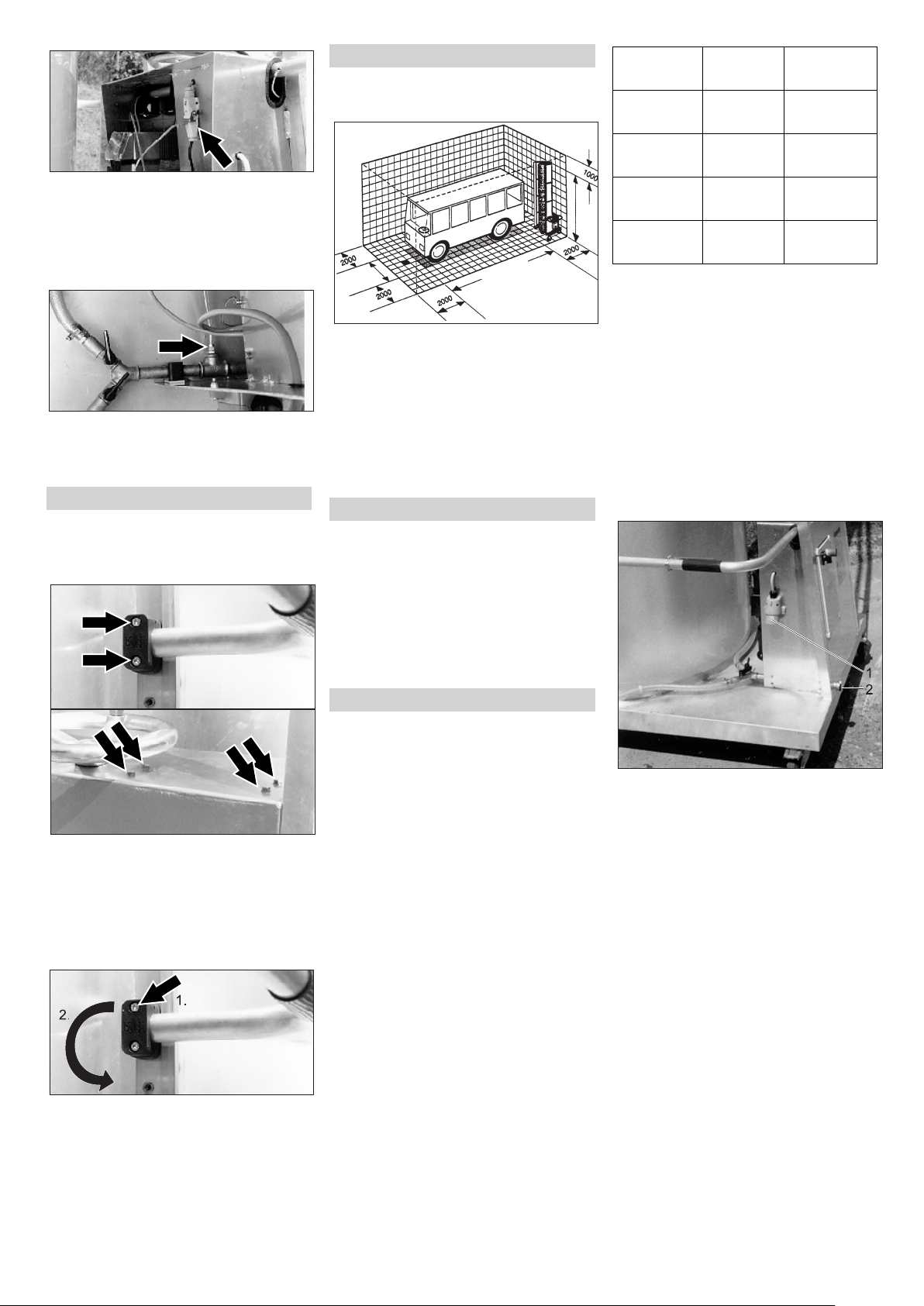
Höhe umstellen:
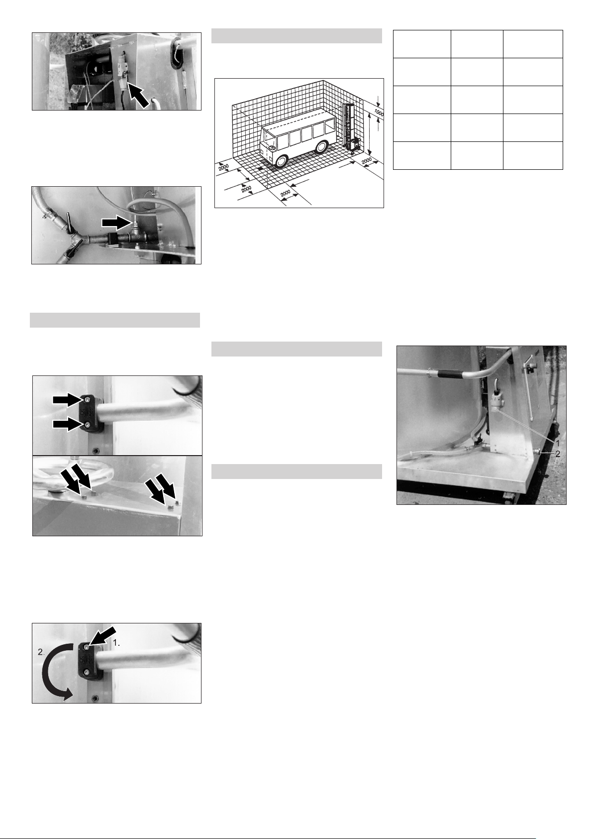
Die nötigen Waschplatzabmessungen sind
oben angegeben.
Anforderungen an den Waschplatz:
– Ebene Fläche.
– Frei von Hindernissen.
– Maximal 2% Gefälle.
– Wasserablauf.
– Trittsichere Gitterroste und Abdeckble-
che.
– Bodenbelag mit rutschsicherer Oberflä-
che.
Wasseranschluss
몇 WARNUNG
Gesundheitsgefahr durch Verunreinigung
des Trinkwassernetzes. Die Waschanlage
darf nicht direkt an das öffentliche Trinkwassernetz angeschlossen werden.
Beim Anschluss an das Trinkwassernetz
muss zwischen Waschanlage und Trinkwassernetz ein Sicherheitsbauteil entsprechend EN 1717 eingebaut werden.
Zuleitungen bereitstellen
230V, 3~, P,
N, 60 Hz
230V, 1~, P,
N, 50 Hz
230V, 1~, P,
N, 50Hz
Die angegebene Länge wird gemessen
von der Vorsicherung bis zur Anlage.
Ist die angegebene Länge nicht ausreichend, bitte beim Hersteller der Anlage
nachfragen.
Die Ausführung des Anschlusses richtet
sich nach der Einsatzart.
– Wird die Anlage an verschiedenen
Waschplätzen eingesetzt, werden Kabel und Wasserschlauch am Boden
nachgezogen.
– Bei fester Installation an einem Wasch-
platz kann die Wasser- und Stromzuführung von oben erfolgen.
Kabelschlepp am Boden
5 x 2,5 H07RN-F
3 x 2,5 H07RN-F
3 x 1,5 H07RN-F
max. 58 m
max. 100 m
max. 60 m
Schrauben lösen.
Handgriff nach unten schwenken, damit
das Kabel des Sicherheitsschalters
nicht beschädigt wird.
Handgriff vorsichtig herausziehen (Ka-
bel des Sicherheitsschalters ist im Griff
verlegt).
Äußere Schraube der Schelle entfer-
nen, Schelle um 180° drehen und
Schraube wieder leicht eindrehen
Handgriff vorsichtig in neuer Position
einschieben und Schellen wieder festziehen.
GEFAHR
Gefährliche elektrische Spannung. Elektroinstallation darf nur durch eine ElektroFachkraft sowie nach den örtlich gültigen
Richtlinien erfolgen.
In der elektrischen Zuleitung muss bauseits
ein Hauptschalter eingebaut sein, welcher
gegen irrtümliches und unbefugtes Einschalten gesichert werden kann.
Die Anlage benötigt folgende Zuleitungen:
– Stromkabel nach nachstehender Tabel-
le.
– Wasserschlauch 3/4“.
Die jeweilige Länge des Wasserschlauches und Stromkabels richtet sich nach
den örtlichen Gegebenheiten bzw. der
Fahrzeuglänge.
Alle vier Fahrzeugseiten sollen in einem
Waschgang ohne Umsetzen der Anlage
gewaschen werden können.
Die Länge des Stromkabels ist aus Sicherheitsgründen begrenzt:
1 Netzstecker
2 Wasseranschluss
Wasserschlauch am Wassereingang
anschließen.
Stromkabel mit dem Netzstecker ver-
binden.
Kabelschlepp über Oberleitung
Die Zuleitungen werden durch einen in der
Höhe verstellbaren Kabelarm zum ersten
Leitungswagen geführt.
Strom- und Wasseranschluss sind fest installiert und müssen durch eine qualifizierte
Fachkraft ausgeführt werden.
6 DE
- 4
Page 7
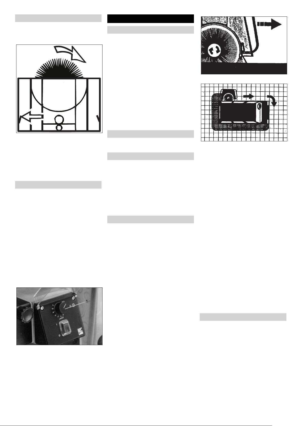
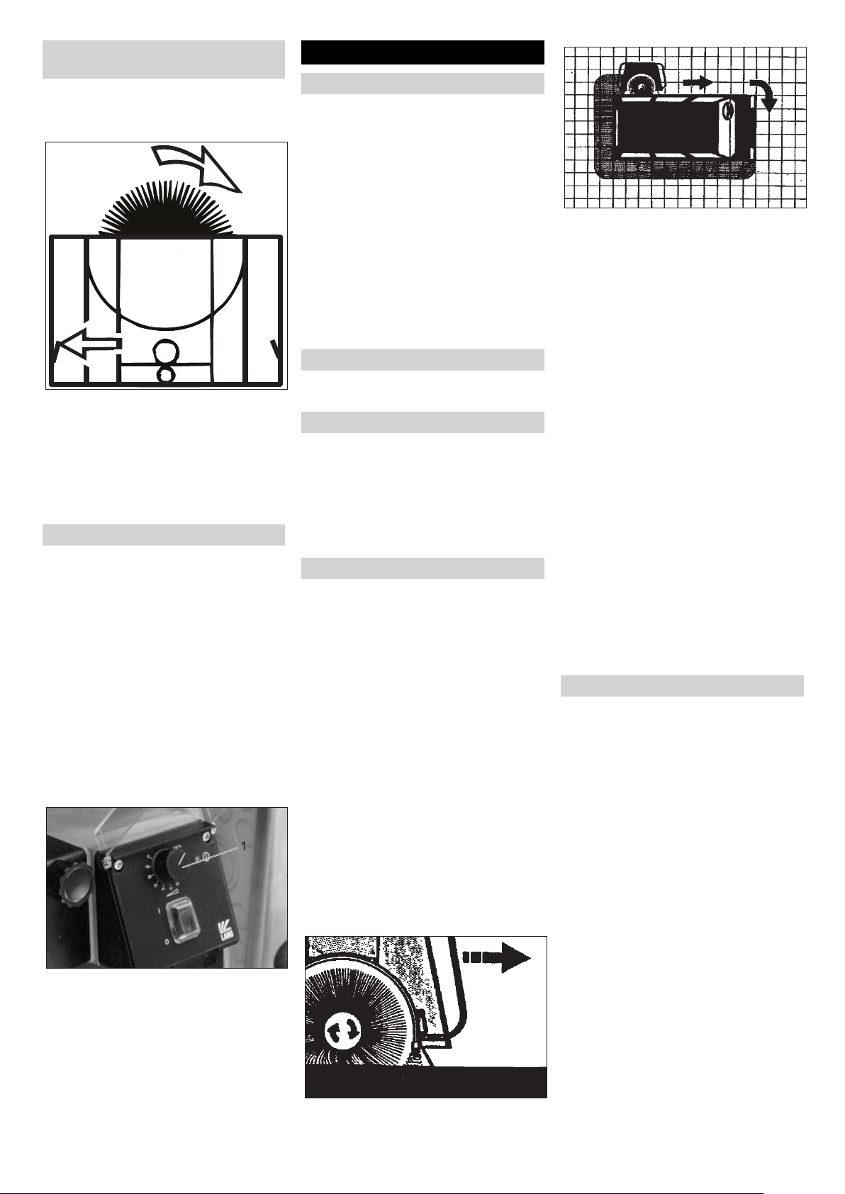
Drehrichtung der Bürste prüfen
Beim ersten Anschluss der Spannungsversorgung muss die Drehrichtung der Bürste
überprüft werden.
Den Sicherheitsschalter betätigen, der
im oben stehenden Bild mit einem Pfeil
gekennzeichnet ist.
Die Bürste muss sich ein Pfeilrichtung
drehen.
Bei falscher Drehrichtung Stroman-
schluss durch Elektrofachkraft ändern
lassen.
Dosierpumpe einstellen
Bei folgenden Anlagen ist keine Dosierpumpe im Standard-Lieferumfang enthalten:
– 1.286-235.0
– 1.286-245.0
– 1.286-345.0
– 1.286-435.0
– 1.286-445.0
Hinweis:
Die Dosiermenge ist vom Werk optimal eingestellt. In der Regel ist keine Neueinstellung notwendig.
VORSICHT
Dosierpumpe kann beschädigt werden.
Drehknopf nur bei laufender Pumpe betätigen.
1 Drehknopf
Drehknopf bei laufender Dosierpumpe
auf gewünschte Dosiermenge drehen.
Die Prozent-Angaben auf der Dosierpumpe
sind bezogen auf die maximale Pumpenleistung.
Betrieb
Vor jedem Betrieb
Hindernisse und herumliegende Ge-
genstände vom Waschplatz entfernen.
Wasseranschluss herstellen.
Stromanschluss herstellen.
Füllstand des Reinigungsmittelbehäl-
ters überprüfen und bei Bedarf nachfüllen.
GEFAHR
Stolpergefahr durch am Boden liegende
Gegenstände oder Zuleitungen.
Vor Inbetriebnahme der Anlage auf
dem Waschplatz liegende Gegenstände entfernen.
Bei Verwendung der Anlage mit Kabel-
schlepp am Boden auf sorgfältige
Nachführung der Zuleitungen achten.
Verhalten im Notfall
Im Notfall Sicherheitsschalter Bürste
loslassen.
Fahrzeug vorbereiten
Fenster, Türen und Dachluken schlie-
ßen.
Seitenspiegel abnehmen oder anklap-
pen.
Antennen einziehen oder abnehmen.
Lose Teile (Planenseile etc.) entfernen
oder sichern.
Planen verschließen und sicher befesti-
gen.
Bedienung
Fahrzeug mittig auf dem Waschplatz
oder unter dem Kabelschlepp abstellen.
Anlage mit Schrägstellkurbel auf die
Neigung der zu reinigenden Fläche einstellen.
Anlage am Anfang einer Fahr-
zeuglängsseite positionieren.
Absperrventil für in Waschrichtung lie-
gendes Düsenrohr öffnen
Hauptschalter einschalten.
Dosierpumpe einschalten.
Anlage am in Waschrichtung liegenden
Handgriff mit beiden Händen festhalten.
VORSICHT
Beschädigungsgefahr. Drehrichtung nicht
bei laufender Bürste ändern.
Bürste durch Ziehen des Sicherheits-
schalters Bürste am jeweiligen Handgriff einschalten.
Bürsteneintauchtiefe
Waschrichtung
Anlage am Handgriff ziehend mit
gleichmäßigem Tempo am Fahrzeug
entlang führen.
Hinweis:
Anlage immer ziehen.
Die Drehrichtung der Bürste ist so gewählt,
dass beim Ziehen der kleinste Kraftaufwand nötig ist.
Bei richtiger Anpresskraft berühren die Distanzrollen das Fahrzeug leicht.
Zu großer Anpressdruck führt nicht zur Verbesserung des Reinigungsergebnisses.
Bei feststehenden, nicht einklappbaren
Spiegeln muss die Anlage etwas vom Fahrzeug weggezogen werden.
An den Fahrzeugecken Anlage neu
ausrichten, eventuell Neigung neu einstellen und Waschvorgang fortsetzen.
VORSICHT
Beschädigungsgefahr für die Zuleitung
durch Verdrillen. Waschrichtung nach jeder
Umrundung des Fahrzeugs wechseln.
Wenn alle Seiten des Fahrzeugs gewaschen sind:
Dosierpumpe ausschalten.
Wasserzulauf auf anderes Düsenrohr
umstellen.
Fahrzeug zum Spülen in entgegenge-
setzter Richtung nochmals umfahren.
Waschvorgang beenden
Waschanlage vom Fahrzeug wegzie-
hen.
Sicherheitsschalter Bürste loslassen.
Dosierpumpe ausschalten.
Wasserzulauf schließen.
Bei längeren Betriebspausen:
Hauptschalter auf Stellung „0“ drehen.
Gegebenenfalls Zuleitung spannungs-
los machen.
- 5
7DE
Page 8
Lagerung
WARNUNG
몇
Verletzungs- und Beschädigungsgefahr!
Gewicht der Anlage der Lagerung beachten.
Anlage zum Abstellplatz schieben.
Bei Kabelschlepp am Boden eventuell
Anschlussleitungen entfernen.
Im Freien und bei offener Halle Anlage
windgeschützt aufstellen oder mit Seil
oder Kette vor dem Umstürzen sichern.
Feststellbremsen an den Rollen anzie-
hen.
GEFAHR
Verletzungsgefahr durch umstürzende Anlage. Anlage windgeschützt aufstellen und
gegen Umstürzen sichern.
Frostschutz
Die wasserführenden Teile der Anlage sind
vor Frost zu schützen, da sie sonst zerstört
werden.
Bei Frostgefahr muss die Anlage vollständig entwässert werden:
Wasserzulauf schließen.
Zuleitung (Wasserschlauch) und Anla-
ge mit Druckluft ausblasen.
Bürstenantrieb einschalten, damit das
Wasser aus der Bürste herausgeschleudert wird.
Wartung und Pflege
Wartungshinweise
Grundlage für eine betriebssichere Anlage
ist die regelmäßige Wartung nach folgendem Wartungsplan.
Verwenden Sie ausschließlich Original-Ersatzteile des Herstellers oder von ihm empfohlene Teile, wie
– Ersatz- und Verschleißteile
– Zubehörteile
– Betriebsstoffe
– Reinigungsmittel
GEFAHR
Gefahr durch elektrischen Schlag.
Anlage spannungsfrei schalten, dazu die
Anlage am Hauptschalter auf „0“ schalten
und gegen Wiedereinschalten sichern.
Gefahr von Augenverletzungen durch wegfliegende Teile oder Schmutz. Nicht in der
Nähe der rotierenden Bürsten aufhalten.
Bei Wartungsarbeiten Schutzbrille tragen.
Wer darf Inspektions-, Wartungs und Instandhaltungsarbeiten durchführen?
Betreiber
Arbeiten mit dem Hinweis „Betreiber“ dürfen nur von unterwiesenen Personen
durchgeführt werden, die Waschanlagen
sicher bedienen und warten können.
Kundendienst
Arbeiten mit dem Hinweis „Kundendienst“
dürfen nur von Kärcher KundendienstMonteuren durchgeführt werden.
Wartungsvertrag
Um einen zuverlässigen Betrieb der Anlage
zu gewährleisten, empfehlen wir Ihnen einen Wartungsvertrag abzuschließen. Wenden Sie sich bitte an Ihren zuständigen
Kärcher-Kundendienst.
Wartungsplan
Zeitpunkt Tätigkeit Betroffene Baugruppe Behebung von
wem
monatlich Schmieren Bürstenlager Schmiernippel mit Fettpresse abschmieren.
Fett 6.288-059.0
Feststellbremse prüfen, bei Bedarf instandsetzen
oder Lenkrolle austauschen
Bei Bedarf Düsen reinigen.
fen.
prüfen. Sauberkeit und Zustand der Borsten prüfen. Der Bürstendurchmesser soll größer als 870
mm sein.
vierteljährlich
Lager Schrägstellspindel
Kette Fett 6.288-059.0 mit Pinsel auftragen. Bediener
Sichtprüfung Lenkrollen Auf Leichtgängigkeit prüfen, bei Bedarf ölen.
Düsen im Düsenrohr. Sprühbild der Düsen prüfen.
Reinigungsmittel-Saugfilter Ablagerungen beseitigen. Bediener
Kabelschlepp (Option) Leitungen auf Beschädigung und Drallfreiheit prü-
Sichtprüfung Bürste Festen Sitz der Segmente und der Endklammer
Bediener
Bediener
Bediener
Bediener
Bediener
8 DE
- 6
Page 9
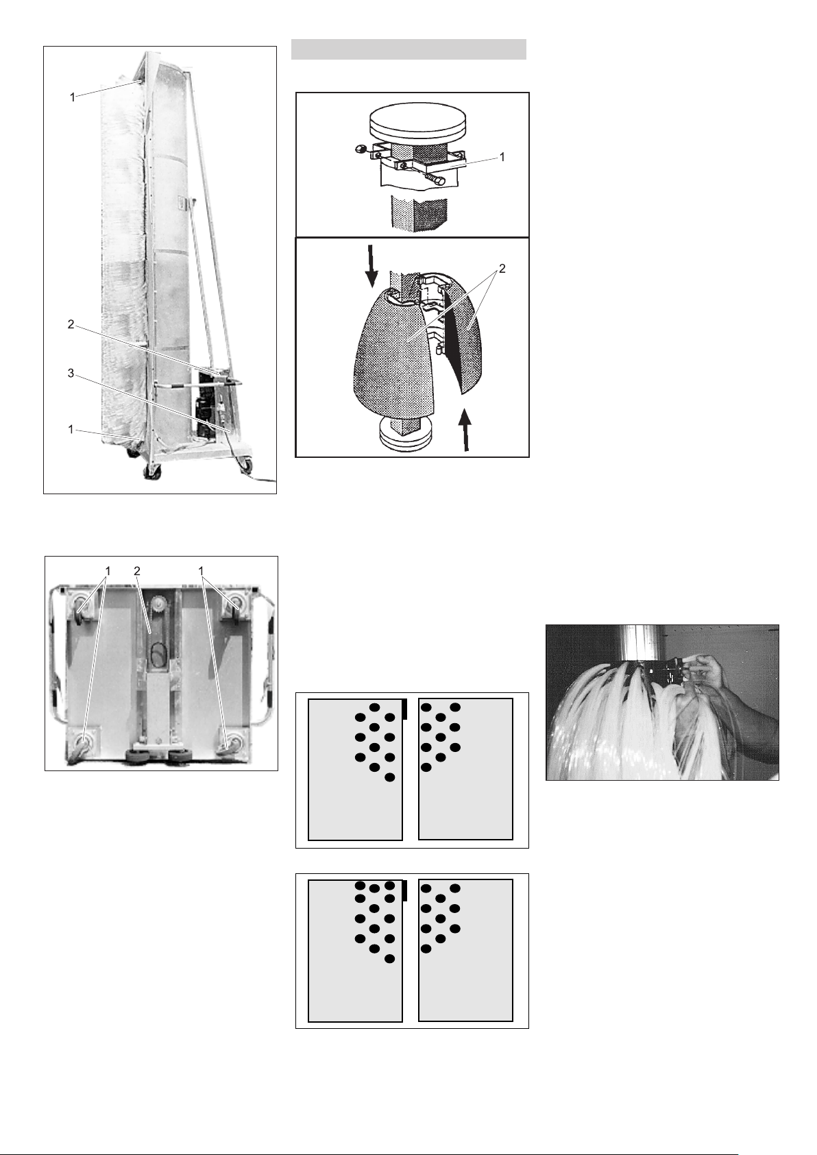
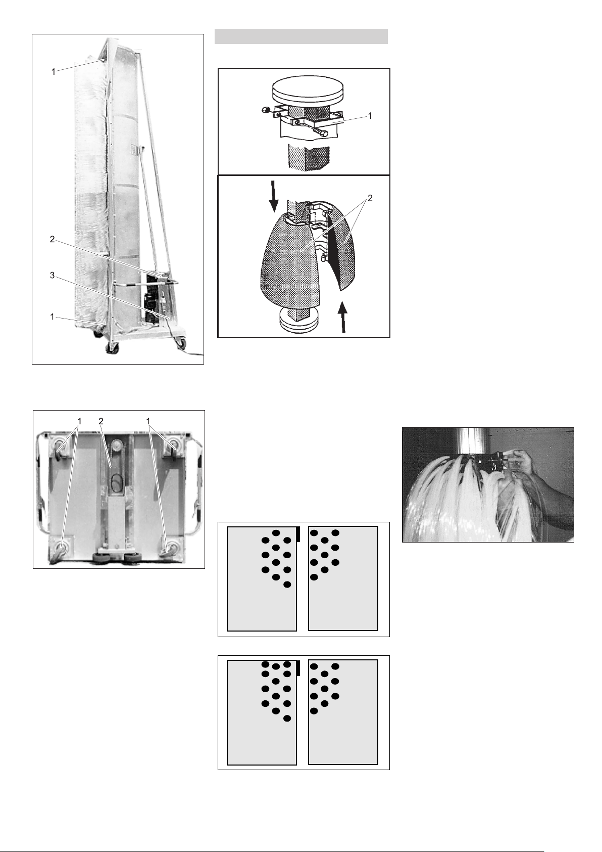
1 Bürstenlager
2 Schrägstellkurbel
3 Lager Schrägstellspindel
Bürstenwechsel
Vierkantwelle mit Halbschalen
1 Endklammer
2 Bürstenhalbschale
GEFAHR
Unfallgefahr bei Arbeiten an der Anlage!
Vor Arbeiten an der Anlage Hauptschalter
ausschalten und sichern.
Schrauben an der Endklammer heraus-
drehen und Endklammer entfernen.
Bürstenhalbschalen gegeneinander
verschieben und von der Bürstenwelle
abnehmen.
Neue Halbschalen montieren wie folgt.
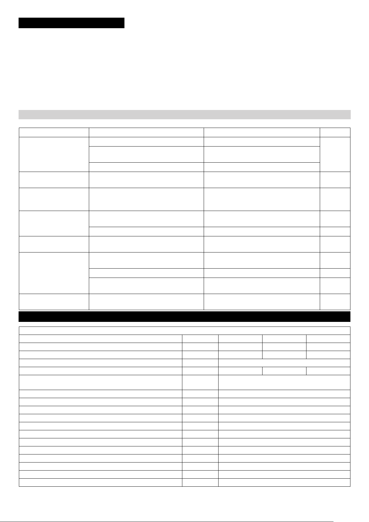
몇 WARNUNG
Unfallgefahr! Bei den Halbschalen kommen zwei verschiedene Typen zum Einsatz, die auf keinen Fall gemischt werden
dürfen. Die Halbschalen können sich sonst
während des Betriebes der Anlage von der
Welle lösen. Die beiden Typen unterscheiden sich durch die Anordnung der Büschel
am Ende bzw. Anfang der Halbschale. Um
eine Unwucht und daraus folgende Beschädigungen zu vermeiden, ist folgendes
zu beachten: Die Halbschalen sind immer
paarweise auszutauschen, also immer ein
ganzes Segment. Entlang der Stoßfuge
müssen die Borstenbüschel der gegenüberliegenden Halbschalen immer versetzt
zueinander sein.
Erstes Halbschalenpaar auf die Welle
setzen und zusammenschieben.
Zweites Halbschalenpaar um 90° ver-
dreht aufsetzen und zusammenschieben.
Weitere Halbschalenpaare jeweils 90°
versetzt auf den Welle anbringen.
Nach der Montage des letzten Halb-
schalenpaars Endklammer anbringen.
Endklammer gegen das letzte Halb-
schalenpaar schieben und Schrauben
festziehen.
Korrekte Montage der Halbschalen und
festen Sitz der Schrauben nochmals
kontrollieren.
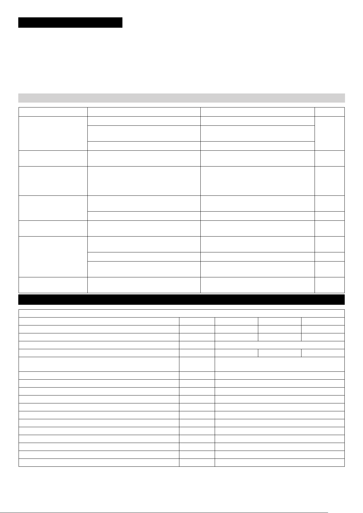
Rundwelle mit Mattenbürsten
GEFAHR
Unfallgefahr bei Arbeiten an der Anlage!
Vor Arbeiten an der Anlage Hauptschalter
ausschalten und sichern.
1 Lenkrolle
2 Kette
Bürstenhalbschalen Typ 1
Bürstenhalbschalen Typ 2
- 7
Schrauben eines Mattensegments lö-
sen und Mattensegment abnehmen.
Weitere Mattensegmente nacheinan-
der entfernen.
Erstes, neues Mattensegment in den
vorgesehenen Löchern montieren.
Jedes folgende Mattensegment um
180° verdreht zum Vorhergehenden
montieren.
Nach abgeschlossener Montage noch-
mals den korrekten Sitz der Mattensegmente und den festen Sitz der
Schrauben kontrollieren.
9DE
Page 10
Störungshilfe
GEFAHR
Gefahr durch elektrischen Schlag.
Arbeiten an der elektrischen Anlage dürfen
nur von Elektrofachkräften ausgeführt werden.
Bei allen Arbeiten die Anlage spannungsfrei schalten, dazu die Anlage am Hauptschalter auf „0“ schalten und gegen
Wiedereinschalten sichern.
Wer darf Störungen beseitigen?
Betreiber
Arbeiten mit dem Hinweis „Betreiber“ dürfen nur von unterwiesenen Personen
durchgeführt werden, die die Waschanlage
sicher bedienen und warten können.
Elektro-Fachkräfte
Personen mit einer Berufsausbildung im
elektrotechnischen Bereich.
Kundendienst
Arbeiten mit dem Hinweis „Kundendienst“
dürfen nur von Kärcher KundendienstMonteuren beziehungsweise von Kärcher
beauftragten Monteuren durchgeführt werden.
GEFAHR
Gefahr durch elektrischen Schlag.
Anlage spannungsfrei schalten, dazu die
Anlage am Hauptschalter auf „0“ schalten
und gegen Wiedereinschalten sichern.
Gefahr von Augenverletzungen durch wegfliegende Teile oder Schmutz. Nicht in der
Nähe der rotierenden Bürsten aufhalten.
Bei Wartungsarbeiten Schutzbrille tragen.
Störungen
Fehler Mögliche Ursache Behebung von wem
Anlage läuft nicht an Keine Stromversorgung Elektrisches Netz überprüfen. Elektro-
Sicherung defekt. Ursache beheben.
Motorschutzschalter hat ausgelöst. Stromaufnahme prüfen.
Bürste kommt nicht auf
Lager schwergängig. Bürstenlager prüfen. Bediener
Drehzahl
Dosierpumpe saugt trotz
Entlüftung und maximaler
Ablagerungen auf Ventilsitzen, verklebte
Ventile.
Dosiermenge nicht an
Dosierpumpe saugt Luft Anschluss Saugventil oder Druckventil un-
dicht.
Pumpenkopf nicht angezogen. Pumpenkopfschrauben anziehen. Bediener
Pumpen der Dosierpumpe
undicht
Dosierpumpe arbeitet
Pumpenkopf nicht angezogen.
Membranfeder gebrochen.
Keine Stromversorgung Spannungsversorgung prüfen und sicherstelnicht, Kontrolllampe leuchtet nicht.
Sicherung defekt. Sicherung auswechseln. Bediener
Platine defekt. Platine austauschen. Elektro-
Sprühbild der Düsen unre-
Düsen verstopft. Düsen reinigen. Bediener
gelmäßig
Sicherung auswechseln.
Saugleitungen und Ventile durchspülen. Bediener
Ventile und Saugleitungen auf Dichtheit prüfen.
Pumpenkopfschrauben anziehen.
Membrane austauschen.
len.
fachkraft
Bediener
Bediener
Bediener
fachkraft
Technische Daten
Anlagenabmessungen
RBS 6012 RBS 6013 RBS 6014
Anlagenhöhe mm 3180 4090 4370
Waschhöhe mm 3645 3925 4205
Anlagenbreite mm 1700
Gewicht kg 234 237 240
Waschplatzbedarf mm Fahrzeuglänge +4000
Fahrzeugbreite + 4000
Wasserfließdruck MPa (bar) 0,3...0,6 (3...6)
Wasseranschluss Zoll 3/4
Wasserverbrauch, ca. l/min 80
Wassertemperatur max. °C 30
Leistungsaufnahme kW 1,1
Schutzart IP54 IP45
Umgebungstemperatur °C +3...+50
Luftfeuchtigkeit, max. % 70
Schalldruckpegel L
Unsicherheit K
pA
pA
Schwingungsgesamtwert Arme m/s
Unsicherheit K m/s
dB(A) 65
dB(A) 4
2
2
<2,5
0,1
10 DE
- 8
Page 11
Lieferumfang
Inhalt Maße Gewicht
lose Anlage RBS 4500mm x 1700 mm x 1100 mm 250 kg
Karton Anlagenzubehör 400 mm x 350 mm x 350 mm 5 kg
Anlagenvarianten
Teilenummer
1.826-205.0 400 V, 3~, P, N, 50 Hz
1.826-215.0 230 V, 3~, P, N, 50 Hz
1.826-225.0 240 V, 1~, P, N, 50 Hz
1.826-235.0 400 V, 3~, P, N, 50 Hz
1.826-245.0 400 V, 3~, P, N, 50 Hz
1.826-801.0 400 V, 3~, P, N, 50 Hz
1.826-802.0 230 V, 3~, P, N, 50 Hz
1.826-803.0 240 V, 1~, P, N, 50 Hz
RBS 6012
1.826-345.0 400 V, 3~, P, N, 50 Hz
RBS 6013
1.862-405.0 400 V, 3~, P, N, 50 Hz
1.862-415.0 230 V, 3~, P, N, 50 Hz
1.862-425.0 240 V, 1~, P, N, 50 Hz
1.862-435.0 400 V, 3~, P, N, 50 Hz
1.862-445.0 400 V, 3~, P, N, 50 Hz
1.862-455.0 230 V, 3~, P, N, 60 Hz
1.862-804.0 400 V, 3~, P, N, 50 Hz
1.862-805.0 230 V, 3~, P, N, 50 Hz
1.862-806.0 240 V, 1~, P, N, 50 Hz
RBS 6014
Spannung
Zubehör
Reinigungsmittel
RM 811
Dosierung:
EU-Konformitätserklärung
Hiermit erklären wir, dass die nachfolgend
bezeichnete Maschine aufgrund ihrer Konzipierung und Bauart sowie in der von uns
in Verkehr gebrachten Ausführung den einschlägigen grundlegenden Sicherheitsund Gesundheitsanforderungen der EURichtlinien entspricht. Bei einer nicht mit
uns abgestimmten Änderung der Maschine
verliert diese Erklärung ihre Gültigkeit.
Produkt: Waschanlage
Typ: 1.826-xxx
Einschlägige EU-Richtlinien
2006/42/EG (+2009/127/EG)
2014/30/EU
Angewandte harmonisierte Normen
EN 60204–1
EN 61000–6–3: 2007 + A1:2011
EN 61000–6–2: 2005
Angewandte nationale Normen
Die Unterzeichnenden handeln im Auftrag
und mit Vollmacht des Vorstands.
Chairman of the Board of Management
Dokumentationsbevollmächtigter:
S. Reiser
Alfred Kärcher SE & Co. KG
Alfred-Kärcher-Straße 28-40
71364 Winnenden (Germany)
Tel.: +49 7195 14-0
Fax: +49 7195 14-2212
Winnenden, 2019/01/01
Director Regulatory Affairs & Certification
Garantie
In jedem Land gelten die von unserer zuständigen Vertriebsgesellschaft herausgegebenen Garantiebedingungen. Etwaige
Störungen an Ihrem Zubehör beseitigen wir
innerhalb der Garantiefrist kostenlos, sofern ein Material- oder Herstellungsfehler
die Ursache sein sollte. Im Garantiefall
wenden Sie sich bitte mit Kaufbeleg an Ihren Händler oder die nächste autorisierte
Kundendienststelle.
Ersatzteile
– Es dürfen nur Zubehör und Ersatzteile
verwendet werden, die vom Hersteller
freigegeben sind. Original-Zubehör und
Original-Ersatzteile bieten die Gewähr
dafür, dass das Gerät sicher und störungsfrei betrieben werden kann.
– Eine Auswahl der am häufigsten benö-
tigten Ersatzteile finden Sie am Ende
der Betriebsanleitung.
– Weitere Informationen über Ersatzteile
erhalten Sie unter www.kaercher.com
im Bereich Service.
Anlage mit Dosierpumpe 0...5 l/h
(0...80ml/min)
Anlage mit Dosierpumpe 0...15 l/h
(0...250 ml/min)
ca. 100 % entspricht 80 ml/min
32...64 % entspricht 80...160
ml/min
Anbausätze
Anbausatz Dosierpumpe
Bestellnummer 3.637-162.0
Vorlagenbehälter
500 l, Bestellnummer 3.070-010.0
1000 l, Bestellnummer 3.070-011.0
Schwimmerventil
Bestellnummer 6.412-765.0
Druckerhöhungsanlage
Bestellnummer 6.473-165.0
Anbausatz Rohrtrenner
Bestellnummer 2.637-650.0
- 9
11DE
Page 12
Please read and comply with
these original instructions prior
to the initial operation of your appliance and
store them for later use or subsequent owners.
Contents
Environmental protection . . EN . . 1
Symbols in the operating in-
structions . . . . . . . . . . . . . . EN . . 1
Safety instructions . . . . . . . EN . . 1
Control elements. . . . . . . . . EN . . 3
Transport. . . . . . . . . . . . . . . EN . . 3
Initial Start-Up . . . . . . . . . . . EN . . 3
Operation . . . . . . . . . . . . . . EN . . 5
Storage . . . . . . . . . . . . . . . . EN . . 6
Maintenance and care . . . . EN . . 6
Troubleshooting . . . . . . . . . EN . . 8
Technical specifications . . . EN . . 8
Accessories . . . . . . . . . . . . EN . . 9
EU Declaration of Conformity EN . . 9
Warranty . . . . . . . . . . . . . . . EN . . 9
Spare parts . . . . . . . . . . . . . EN . . 9
Environmental protection
The packaging materials are
recyclable. Please do not throw
packaging in the domestic
waste but pass it on for recy-
cling.
Old units contain valuable recy-
clable materials. Batteries, oil
and similar substances may
not be released into the envi-
ronment. Therefore please dis-
pose of old units through
suitable collection systems.
Ensure that gear oil is not released into the
environment. Protect the ground and dispose of used oil in an environmentallyclean manner.
Do not let waste water containing mineral
oil spill into the soil, into waters or without
treatment into the discharge channel. Observe the locally valid regulations and
waste water by-laws
Notes about the ingredients (REACH)
You will find current information about the
ingredients at:
www.kaercher.com/REACH
Symbols in the operating in-
structions
DANGER
Immediate danger that can cause severe
injury or even death.
몇 WARNING
Possible hazardous situation that could
lead to severe injury or even death.
CAUTION
Possible hazardous situation that could
lead to mild injury to persons or damage to
property.
Safety instructions
Safety instructions
General
To avoid danger to persons, animals and
property before the first operation of the
system, read:
– the operating manual
– all safety instructions
– the respective national statutes of the
legislator
– the safety instructions which are at-
tached to the used detergents (normally
on the packing label).
For the operation of this system the following regulations and directives are applicable in the Federal Republic of Germany
(available from Carl Heymanns Verlag KG,
Luxemburger Straße 449, 50939 Cologne):
– Accident prevention provision "General
rules and regulations" BGV A1
– Order in respect of operational safety
(BetrSichV).
Ensure:
– that you have understood all the in-
structions
– that all users of the plant are informed
about the instructions and have understood them.
These operating instructions must be
changed into operating rules by the operator of the washing system while observing
the local and personnel guidelines. These
operating instructions must be displayed in
a suitable location at the workplace.
Vehicle washing plants
Only persons may be entrusted with the operation, monitoring, servicing, maintenance
and checking of the vehicle washing plants
who are familiar with these works and are
acquainted with the operating manual, and
who have been instructed about the dangers involved with the plant.
Self-service
Self-service vehicle wash plants must have
a person available on operational standby
who is familiar with the plant and, in the
event of an operational failure, who is able
to perform, or arrange for, the necessary
measures to avoid possible dangers.
Instructions concerning the operation and
intended use of the plant must be posted
where they can be easily seen at the washing place.
Maintenance
Maintenance work may be carried out only
when the plant is switched off. In this case,
the main switch must be protected against
unauthorized restarting.
Hazardous materials
Take protective measures when handling
cleaning agent concentrates which contain
hazardous substances. Especially goggles, protective gloves and personal protective clothing must be worn and the
instruction leaflets/safety data sheets attached to the detergents have to be observed.
Entering the vehicle washing plant
Unauthorized persons may not enter the
vehicle washing plant. The entry prohibition
is to be indicated continually and in a clearly recognisable way.
Danger of slipping
Danger of slipping in the plant from moisture on the floor and on the plant sections.
Move with care when working on the plant
and wear suitable footwear. Washing customers must be warned of the danger of
slipping through suitable notices.
Operation of the plant
몇 WARNING
To avoid danger through false operation,
the plant must be operated only by persons,who
– are instructed in its operational handling
– have proved their capabilities in respect
of operation
– have been explicitly commissioned to
use it.
The operating manual must be made available to each user. The plant may not be operated by persons under 18 years old.
Trainees over 16 years old and under supervision are exceptions here.
Proper use
The RBS 6000 is designed for the brushwashing of busses and transport vehicles,
lorries, lorries with trailers and articulated
lorries. The incline of the side walls of the
vehicles must be smaller than 10 degrees.
The system can be used inside a washing
hall or outdoors.
The proper use also includes:
– observing all instructions in this operat-
ing manual and
– the compliance with the inspection and
maintenance instructions.
CAUTION
Increased risk of corrosion by using inappropriate detergents.
The following detergents must not be processed by the installation:
– detergents intended for the cleaning of
the wash hall.
– detergents intended for the exterior
cleaning of the washing system.
– Detergents which are applied to the ve-
hicle by a separate device (such as rim
cleaners).
– Detergents to treat wastewater.
Only use KÄRCHER-approved detergents.
12 EN
- 1
Page 13

Workstation
The system is held on to with both hands at
the handle and dragged along the vehicle.
Here, you must activate the respective
safety switch for the brush with one hand.
Non-intended use
CAUTION
Risk of damage! The RBS 6000 is only suitable for the cleaning of vehicles with
straight, smooth side walls, whose incline is
smaller than 10°.
The operator of this cleaning system is liable for all damages incurred by improper
use; this applies specifically to the cleaning
of vehicles that are not listed in these instructions.
Sources of danger
General dangers
DANGER
Risk of eye injuries from leaking air pressure. The pneumatic parts of the plant still
remain under high air pressure after the
main switch or emergency switch has been
switched off.
Risk of injury from parts flying off! Flying-off
fragments or objects can injure people or
animals. Therefore the hall floors must be
kept clear of loose objects lying around.
Danger of explosion
DANGER
Risk of explosion! The plant must not be
operated in the near to rooms that are exposed to danger of explosion. Excepted
from this are only plants that are explicitly
intended and designated. No explosive,
highly ignitable or poisonous substances
must be used, as e.g.:
– petrol
– heating oil and diesel fuel
– solvents
– liquids containing solvents
– non-diluted acid
– acetone
If you are unsure, ask the manufacturer.
Damage to hearing
The noises emitted by the plant are not
dangerous. However, if parts that amplify
sound are shot blasted, it can give rise to
higher noise levels. If so, wear ear plugs.
Electrical dangers
DANGER
Risk of electric shock.
– Never touch electrical cables, plug con-
nections and terminal boxes with wet
hands.
– Electrical connecting leads or extension
cables must not be damaged through
being driven over, crushed, or pulled or
the like. Protect the power cord from
heat, oil, and sharp edges.
– With mobile cleaning devices (e.g. with
high-pressure cleaners) the water jet
must never be aimed at electrical appliances or units.
– All current-conducting parts in the work-
ing area must be protected against jet
water.
– Plants must only be connected to prop-
er earthed power sources.
– All work on electrical parts of the plant
must be carried out only by a qualified
electrician.
– Accessories that are not directly con-
nected to the system, must be integrated into the equipotential bonding.
Danger from substances that are harmful to health
DANGER
The detergents used contain partly substances that are harmful to health; therefore it is absolutely necessary to observe
the enclosed or printed instructions.
Do not drink the water emitted from the
plant! There is no drinking water quality
present due to the mixed detergents.
Should processed water be used to operate the plant, then the stipulations of the
manufacturer of the water treatment plant
on germination inhibition must be observed.
Substances which do not generally occur
usually in the exterior cleaning of vehicles
(e.g. chemicals, heavy metals, pesticides,
radioactive materials, faeces or epidemic
matter) must not reach the wash plant.
Danger from power failure
An uncontrolled restart of the plant following power failure is ruled out because of
construction measures that have been taken.
The brush will only turn if a safety switch is
activated.
Danger to the environment from waste
water
The locally valid regulations on waste water
disposal are to be observed.
Maintenance and monitoring
In order to ensure a safe operation of the
plant and to prevent dangers during maintenance, monitoring and inspection, the
corresponding instructions have to adhered
to.
Maintenance
Maintenance work must be carried out by a
specialist at regular intervals in accordance
with the specifications of the manufacturer.
The existing stipulations and safety requirements are to be here observed. Work
on the electrical plant may only be carried
out by qualified electricians.
DANGER
Risk of injury. The system must be
switched off and secured against against
any unintentional and unauthorised restart
before maintenance and servicing can be
carried out.
Monitoring
This vehicle wash plant must be inspected
for its safe operational state before being
put into operation and afterwards at least
half-yearly by a specialist. The scope of this
inspection specifically includes:
– visible inspection for externally recog-
nisable wear and damage respectively
– Function test
– completeness and effectivity of safety
installations for self-operation plants
daily before start of operation, for monitored plants according to requirements
but at least once monthly.
Use original parts.
Use exclusively original parts of the manufacturer or those parts recommended by
him as otherwise claims made under the
warranty will be rendered void. Observe all
instructions on safety and use which are
accompany these parts. This concerns:
– replacement and wear parts
– accessories
– Fuel
– detergents.
Emergency stop button
DANGER
Risk of accident due to defective safety
equipment! The system is equipped with an
emergency off switch and two "brush safety
switches“.
Safety equipment must be checked for
proper function as needed, but at least
once a month.
- 2
13EN
Page 14
Control elements
1 Rotary knob for dosing pump*
2 Switch for dosing pump*
3 Handle
4 Safety switch (brush)
5 Mains plug
6 Shutoff valves for nozzle pipes
7 Main switch
8 Water connection
9 Emergency-stop button
10 Incline crank
Transport
몇 WARNING
Risk of injury and damage! Observe the
weight of the system when you transport it.
This system can be transported on the bed
of a lorry laying down:
Remove the spacer rollers.
Tilt the system onto the brush side with
two people.
Slide the system onto the lorry bed.
Secure the system from sliding.
Initial Start-Up
Install spray guard
1 Splash guard
2 Pin
3 Expanding rivet
4 Angle profile
The two angle profiles are attached to the
frame with expanding rivets for transport,
remember the installation position of
the angle profiles for the assembly
process.
Hit the pins of the expanding rivets to-
ward the inside with a punch.
Remove the angle profiles.
Roll out the included spray guard and
place it on the square pipe.
Note:
The spray guard strips are ondulated on
their short side. During installation, this ondulation must face away from the brush.
Reinstall the angle profile.
Insert the expanding rivet through the
angle profile, spray guard and the
square pipe and press in firmly.
Hit the pin of the expanding rivet with
the hammer.
Repeat this process for all bores in the
angle profiles.
Install the spacer rollers
Fasten the two included spacer rollers
on the frame of the system.
Select the height according to the vehi-
cles to be washed.
Tighten the counter nuts.
Install the dosing pump
The following systems do not include a
dosing pump in the standard scope of delivery:
– 1.286-235.0
– 1.286-245.0
– 1.286-345.0
– 1.286-435.0
– 1.286-445.0
Fasten the dosing pump on the frame of
the system with the included fasteners.
14 EN
- 3
Page 15
Washing station
The system can be used inside a washing
hall or outdoors.
Electrical
connection
400V, 3~, P,
N, 50 Hz
Cable type Length
5 x 2.5 H07RN-F
max. 100 m
Connect the cable of the dosing pump.
Fill the detergent tank and place it on
the base plate of the system.
Insert the suction hose of the dosing
pump with suction filter into the tank
and screw on the lid.
Insert the hose from the dosing pump
outlet into the screw connection on the
water distributor and tighten the acorn
nut.
Adjust the handle
The handles can be attached in two positions.
Resetting the height:
The required washing station dimensions
are indicated above.
Washing station requirements:
– Even surface.
– Free of obstacles.
– Maximal decline 2%.
– Water drainage
– Step-safe grids and cover plates.
– Floor covering with anti-slip surface.
Water connection
몇 WARNING
Health hazard on account of contamination
of the drinking water network. The washing
system must not be connected to the public
drinking water network.
When connected to the drinking water network, a safety component as per EN 1717
must be installed between the washing system and the drinking water network.
Provide supply lines
230V, 3~, P,
N, 60 Hz
230V, 1~, P,
N, 50 Hz
230V, 1~, P,
N, 50Hz
The indicated length is measured from the
prefuse to the system.
If the indicated length is not sufficient,
please enquire with the manufacturer of the
system.
The model of the connection depends on
the type of use.
– If the system is to be used at different
washing stations, the cable and the water hose are dragged along the floor.
– With fixed installations at one washing
station, the water and electricity can be
supplied from above.
Cable drag on the floor
5 x 2.5 H07RN-F
3 x 2.5 H07RN-F
3 x 1.5 H07RN-F
max. 58 m
max. 100 m
max. 60 m
Loosen the screws.
Swivel the handle down in order to en-
sure that the cable of the safety switch
is not damaged.
Carefully pull out the handle (cable of
the safety switch is routed in the handle).
Remove the outer screw of the clamp,
rotate the clamp by 180° and lightly turn
the screw back in.
Carefully slide the handle into the new
position and retighten the clamps.
DANGER
Risk of electrical voltage. All electrical installations may only be done by an electrician according to the local regulations.
A site-supplied main switch must be installed in the electric supply line, which can
be protected against inadvertent or unauthorised access.
The system requires the following supply
lines:
– Mains cable as per the following table.
– Water hose 3/4".
The respective length of the water hose
and the mains cable depends on the local
conditions or the length of the vehicle.
All four sides of the vehicle should be
washed in one washing run without modifying the system.
The length of the mains cable is limited for
safety reasons.
1 Mains plug
2 Water connection
Connect the water hose to the water in-
let.
Connect the mains cable to the mains
plug.
Cable drag over overhead line
The supply lines are routed through a
height-adjustable cable arm to the first line
cart.
Electric and water connections are stationary installations and must be conducted by
a qualified technician.
- 4
15EN
Page 16
Check the rotation direction of the
brush.
When the voltage supply is first connected,
the rotation direction of the brush must be
checked.
Activate the safety switch, which is
marked by an arrow in the above illustration.
The brush must rotate in the direction of
the arrow.
If the rotational direction is wrong, get
an electrician to modify the electrical
connection.
Setting the dosing pump
The following systems do not include a
dosing pump in the standard scope of delivery:
– 1.286-235.0
– 1.286-245.0
– 1.286-345.0
– 1.286-435.0
– 1.286-445.0
Note:
The dosing volume is factory optimised.
Generally no reset is necessary.
CAUTION
Dosing pump can be damaged. Activate
the rotary knob only when the pump is running.
Operation
Before each use
Remove all obstacles and objects in the
way of the washing station.
Create a water connection.
Create an electrical connection.
Check filling level of the detergent con-
tainer and refill if required.
DANGER
Risk of stumbling due to objects on the floor
or supply lines.
Prior to taking the system into opera-
tion, remove all objects from the washing station.
When using a system with a cable drag,
observe the proper routing of the supply
lines.
Behaviour in emergency situations
In emergencies, release the brush safe-
ty switch.
Preparing the vehicle
Close windows, doors and roof open-
ings.
Remove or fold in the side mirror.
Retract or remove antennas.
Remove or secure loose parts (tarp
ropes, etc.).
Close tarps and secure fasten them.
Operations
Park the vehicle centered at the wash-
ing station or underneath the cable
drag.
Adjust the system to the incline of the
surface to be cleaned by means of the
incline crank.
Position the system at the start the long
side of the vehicle.
Open the shutoff valve for a nozzle pipe
located in the direction of the washing
process
Turn on the main switch.
Switch on the dosing pump.
Hold the system with both hands on the
handle in washing direction.
CAUTION
Risk of damage. Do not change the rotation
direction while the brush is running.
Switch on the brush by pulling on the
safety switch of the brush on the respective handle.
Washing direction
Guide the system along the vehicle at
an even speed by pulling on the handle.
Note:
Always pull - never push the system.
The rotation direction of the brush is selected to cause the least amount of power effort during pulling.
If the correct contact pressure is used, the
spacer rollers will touch the vehicle lightly.
Too much contact pressure will not improve
the cleaning effect.
If there are stationary, non-foldable mirrors,
the system must be pulled away from the
vehicle slightly.
Reposition the system at the corners of
the vehicle, readjust the incline if necessary and continue the washing process.
CAUTION
Risk of damage to the supply lines due to
twisting. Change the washing direction
every time you come around the vehicle.
Once all sides of the vehicle have been
washed:
Switch off the dosing pump.
Switch the water supply to another noz-
zle pipe.
Go around the vehicle one more time in
the opposite direction for rinsing.
Finish the washing process
Pull the washing system away from the
vehicle
Release the brush safety switch.
Switch off the dosing pump.
Shut off water supply.
In case of longer operational breaks:
Turn the main switch to position “0”.
Remove the voltage from the supply
line if desired.
1 Rotary knob
With the dosing pump running, turn the
rotary knob to the desired dosage
amount.
The percentages listed on the dosing pump
refer to max. pump performance.
Brush submersion depth
16 EN
- 5
Page 17
Storage
WARNING
몇
Risk of injury and damage! Observe the
weight of the system when you store it.
Push the system to the storage area.
If there is a cable drag on the floor, you
might need to disconnect the supply
lines.
If outdoors or in an open hall, store the
system protected from wind or secure it
from tipping over by means of ropes or
chains.
Activate the parking brakes on the roll-
ers.
DANGER
Risk of injury due to system toppling over.
Store the system protected from wind and
protect it from tipping over.
Frost protection
Protect the water-carrying parts of the plant
against frost because they can get totally
damaged.
If there is a chance of frost, the system
must be drained completely:
Shut off water supply.
Blow the supply line (water hose) and
the system out with compressed air.
Switch on the brush drive so that the
water is ejected from the brush.
Maintenance and care
Maintenance instructions
The bases of a safe operating of the equipment is thr regularly maintenance according to the following maintenance plan.
Use exclusively original parts of the manufacturer or those parts recommended by
him like
– replacement and wear parts
– Accessory parts
– Fuel
– Detergent
DANGER
Risk of electric shock.
Switch on the plant voltage-free, in addition
switch on the main switch to “0” and secure
it against being switched on again.
Risk of eye injuries from parts flying off or
dirt. Keep clear off rotating brushes. Goggles must be worn during maintenance
work.
Who may carry out maintenance and
servicing?
Operator
Work designated with the sign “Operator”
may only be carried out by persons who
have been instructed in the safe operation
and maintenance on the washing system.
Customer Service
Work designated with the sign “Customer
Service” may only be done by the fitters of
Kärcher Customer Service.
Maintenance contract
In order to guarantee a reliable operation of
the equipment, we success, you signed a
maintenance agreement. Please refer to
your local Kärcher service department.
Maintenance schedule
Time Activity Assembly affected Remedy of whom
monthly Lubricate Brush bearing Lubricate the greasing nipple with a grease press.
Storage of the inclining spindle
Chain Apply the grease 6.288-059.0 with a paint brush. Operator
Visual inspection Swivel casters Check for ease of movement; oil if required.
Nozzles in the nozzle pipe. Check spray pattern of the nozzles.
Detergent suction filter Remove the deposits. Operator
Cable drag (option) Check the lines for damage and twisting. Operator
Quarterly Visual inspection Brush Check the tight seating of the segments and the
Grease 6.288-059.0
Check the parking brake, repair if necessary or replace the steering roller.
Clean the nozzles as needed.
end clip. Check the cleanliness and condition of
the bristles. The brush diameter should be larger
than 870 mm.
Operator
Operator
Operator
Operator
- 6
17EN
Page 18
1 Brush bearing
2 Incline crank
3 Storage of the inclining spindle
Brush replacement
Square shaft with semi-bowls
1 Terminal clip
2 Brush semi-bowl
DANGER
Risk of accident while working on the unit!
Before starting any work on the plant,
switch off the main switch and ensure that
it will not be put on accidentally.
Loosen the screws on the end clip and
remove the end clip.
Slide the brush semi-bowls away from
each other and remove them from the
brush shaft.
Install the new semi-bowls as follows.
몇 WARNING
Danger of accident! With semi-bowls, two
different styles are used, which must never
be mixed. Otherwise, the semi-bowls could
come loose from the shaft during system
operation. The two styles differ based on
the location of the bushels at the end or
start of the semi-bowl. In order to prevent
imbalance and damages caused by this,
the following points must be observed: The
semi-bowls must always be replaced as
sets, i.e. always as a whole segment. The
bristle bushels must be offset to the opposite semi-bowls along the the butt joint.
Place the first pair of semi-bowls on top
of the shaft and slide them together.
Place the second pair of semi-bowls on
top of the shaft rotated by 90° and slide
them together.
Install the other semi-bowl pairs on the
shaft offset by 90° each.
After installing the last semi-bowl pair,
install the end clip.
Slide the end clip against the last semi-
bowl pair and tighten screws.
Finally, recheck the proper installation
of the semi-bowls and tight seating of
the screws.
Round shaft with mat brushes
DANGER
Risk of accident while working on the unit!
Before starting any work on the plant,
switch off the main switch and ensure that
it will not be put on accidentally.
1 Steering roller
2 Chain
Brush semi-bowls type 1
Brush semi-bowls type 2
18 EN
Loosen the screw of one mat segment
and remove the mat segment.
Remove the other mat segments con-
secutively.
Install the first new mat segment in the
appropriate bores.
Install every subsequent mat segment
rotated by 180° compared to the previous one.
After installation, recheck the proper
seating of the mat segments and the
tight fit of the screws.
- 7
Page 19
Troubleshooting
Danger
Risk of electric shock!
Work on electrical plant only to be carried
out by qualified electricians.
Switch the plant to voltage-free with all
work, in this case switch the plant at the
main switch to “0”and secure against it
switching on again.
Who may remedy faults?
Operator
Work designated with the sign “Operator”
may only be carried out by persons who
have been instructed in the safe operation
and maintenance on the wash plant
Electricians
Persons with a professional training in the
electro-technical area.
Customer Service
Work designated with the sign “Customer
Service” may only be done by the fitters of
Kärcher Customer Service or fitters who
have been authorised by Kärcher.
DANGER
Risk of electric shock.
Switch on the plant voltage-free, in addition
switch on the main switch to “0” and secure
it against being switched on again.
Risk of eye injuries from parts flying off or
dirt. Keep clear off rotating brushes. Goggles must be worn during maintenance
work.
Faults
Fault Possible cause Remedy of whom
Plant is not running No power supply Check electrical mains. Qualified
Fuse defective. Remove the cause.
Protective motor switch was triggered. Check the current pickup.
Brush is does not reach re-
Bearings stuck. Check the brush bearing. Operator
quired speed
Dosing pump does not
Residue on valve seats, stuck valves. Flush the suction hoses and valves. Operator
suck in spite of ventilation
and maximum dosing volume
Dosing pump sucks air Connection of suction valve or pressure
valve leaks.
Pump head not tightened. Tighten the pump head screws. Operator
Pumps of the dosing pump
leak
Dosing pump does not op-
Pump head not tightened.
Membrane spring broken.
No power supply Check power supply and ensure proper superate even though the indicator lamp is lit.
Fuse defective. Replace the fuse. Operator
PCB defective. Replace PCB. Qualified
Spray pattern of the noz-
Nozzles are blocked. Clean the nozzles. Operator
zles irregular.
Replace the fuse.
Check the valves and suction hoses for leaks. Operator
Tighten the pump head screws.
Replace the membrane.
ply.
electrician
Operator
Operator
electrician
Technical specifications
Plant dimensions
RBS 6012 RBS 6013 RBS 6014
System height mm 3180 4090 4370
Washing height mm 3645 3925 4205
System width mm 1700
Weight kg 234 237 240
Washing station requirements mm Vehicle length +4000
Vehicle width + 4000
Water flow pressure MPa (bar) 0,3...0,6 (3...6)
Water connection Inch 3/4
Water consumption, approx. I/min 80
Max. water temperature °C 30
Power Input kW 1,1
Type of protection IP54 IP45
Ambient temperature °C +3...+50
Humidity, max. % 70
Sound pressure level L
Uncertainty K
pA
pA
Vibration total value on arms m/s
Uncertainty K m/s
dB(A) 65
dB(A) 4
2
2
<2,5
0,1
- 8
19EN
Page 20
Scope of delivery
Contents Dimensions Weight
loose RBS system 4,500mm x 1,700 mm x 1,100 mm 250 kg
Carton System accessories 400 mm x 350 mm x 350 mm 5 kg
System models
Part
number
1.826-205.0 400 V, 3~, P, N, 50 Hz
1.826-215.0 230 V, 3~, P, N, 50 Hz
1.826-225.0 240 V, 1~, P, N, 50 Hz
1.826-235.0 400 V, 3~, P, N, 50 Hz
1.826-245.0 400 V, 3~, P, N, 50 Hz
1.826-801.0 400 V, 3~, P, N, 50 Hz
1.826-802.0 230 V, 3~, P, N, 50 Hz
1.826-803.0 240 V, 1~, P, N, 50 Hz
RBS 6012
1.826-345.0 400 V, 3~, P, N, 50 Hz
RBS 6013
1.862-405.0 400 V, 3~, P, N, 50 Hz
1.862-415.0 230 V, 3~, P, N, 50 Hz
1.862-425.0 240 V, 1~, P, N, 50 Hz
1.862-435.0 400 V, 3~, P, N, 50 Hz
1.862-445.0 400 V, 3~, P, N, 50 Hz
1.862-455.0 230 V, 3~, P, N, 60 Hz
1.862-804.0 400 V, 3~, P, N, 50 Hz
1.862-805.0 230 V, 3~, P, N, 50 Hz
1.862-806.0 240 V, 1~, P, N, 50 Hz
RBS 6014
Voltage
Accessories
Detergent
RM 811
Dosage:
EU Declaration of Conformity
We hereby declare that the machine described below complies with the relevant
basic safety and health requirements of the
EU Directives, both in its basic design and
construction as well as in the version put
into circulation by us. This declaration shall
cease to be valid if the machine is modified
without our prior approval.
Product: Washing plant
Type: 1.826-xxx
Relevant EU Directives
2006/42/EC (+2009/127/EC)
2014/30/EU
Applied harmonized standards
EN 60204–1
EN 61000–6–3: 2007 + A1:2011
EN 61000–6–2: 2005
Applied national standards
The signatories act on behalf of and with
the authority of the company management.
Chairman of the Board of Management
Documentation supervisor:
S. Reiser
Alfred Kärcher SE & Co. KG
Alfred-Kärcher-Straße 28-40
71364 Winnenden (Germany)
Tel.: +49 7195 14-0
Fax: +49 7195 14-2212
Winnenden, 2019/01/01
Director Regulatory Affairs & Certification
Warranty
The warranty terms published by our competent sales company are applicable in
each country. We will repair potential failures of your accessory within the warranty
period free of charge, provided that such
failure is caused by faulty material or defects in fabrication. In the event of a warranty claim please contact your dealer or the
nearest authorized Customer Service center. Please submit the proof of purchase.
Spare parts
– Only use accessories and spare parts
which have been approved by the manufacturer. The exclusive use of original
accessories and original spare parts
ensures that the appliance can be operated safely and trouble free.
– At the end of the operating instructions
you will find a selected list of spare
parts that are often required.
– For additional information about spare
parts, please go to the Service section
at www.kaercher.com.
System with dosing
pump 0...5 l/h (0...80
ml/min)
System with dosing
pump 0..0.15 l/h
(0..0.250 ml/min)
approx. 100%
equals 80 ml/min
32...64 % equals
80...160 ml/min
Attachment sets
Upgrade kit dosing pump
Order no. 3.637-162.0
Storage tanks
500 l, order no. 3.070-010.0
1.000 l, order no. 3.070-011.0
Swimmer valve
Order no. 6.412-765.0
Pressure increasing unit
Order no. 6.473-165.0
Upgrade kit pipe separator
Order no. 2.637-650.0
20 EN
- 9
Page 21
Lire ce manuel d'utilisation origi-
nal avant la première utilisation
de votre appareil, le respecter et le conserver pour une utilisation ultérieure ou pour le
futur propriétaire.
Table des matières
Protection de l’environnement FR . . 1
Symboles utilisés dans le mode
d'emploi. . . . . . . . . . . . . . . . FR . . 1
Consignes de sécurité . . . . FR . . 1
Eléments de commande . . . FR . . 3
Transport. . . . . . . . . . . . . . . FR . . 3
Première mise en service . . FR . . 3
Fonctionnement . . . . . . . . . FR . . 5
Entreposage . . . . . . . . . . . . FR . . 6
Entretien et maintenance . . FR . . 6
Service de dépannage . . . . FR . . 8
Caractéristiques techniques FR . . 8
Accessoires . . . . . . . . . . . . FR . . 9
Déclaration UE de conformité FR . . 9
Garantie . . . . . . . . . . . . . . . FR . . 9
Pièces de rechange . . . . . . FR . . 9
Protection de l’environne-
ment
Les matériaux constitutifs de
l'emballage sont recyclables.
Ne pas jeter les emballages
dans les ordures ménagères,
mais les rendre à un système
de recyclage.
Les appareils usés contiennent
des matériaux précieux recyclables lesquels doivent être
rendus à un système de recyclage. Des batteries, de l’huile
et d'autres substances semblables ne doivent pas être tout
simplement jetées. Pour cette
raison, utiliser des systèmes
adéquats de collecte pour éliminer les appareils usés.
L'huile d'engrenage ne doit pas endommager l'environnement. Protéger le sol et évacuer l'huile usée de façon favorable à
l'environnement.
Ne pas évacuer les eaux usées contenant
des huiles minérales dans le sol, les cours
d'eaux ni même dans les canalisations
sans traitement préalable. Merci de
prendre en considération les dispositions
légales locales ainsi que les statuts des
eaux usées.
Instructions relatives aux ingrédients
(REACH)
Les informations actuelles relatives aux ingrédients se trouvent sous :
www.kaercher.com/REACH
Symboles utilisés dans le
mode d'emploi
DANGER
Pour un danger immédiat qui peut avoir
pour conséquence la mort ou des blessures corporelles graves.
몇 AVERTISSEMENT
Pour une situation potentiellement dangereuse qui peut avoir pour conséquence des
blessures corporelles graves ou la mort.
PRÉCAUTION
Pour une situation potentiellement dangereuse qui peut avoir pour conséquence des
blessures légères ou des dommages matériels.
Consignes de sécurité
Consignes de sécurité
Généralités
Pour éviter des risques corporels et matériels, lisez avant la première mise en service de l'installation ce qui suit:
– les instructions de service
– toutes les consignes de sécurité
– les directives légales en vigueur dans le
pays d'exploitation
– les consignes de sécurité fournies avec
les détergents utilisés (par exemple sur
l'étiquette de l'emballage).
Les prescriptions et les directives suivantes
sont en vigueur pour exploiter ce portique
en Allemagne (disponibles chez Carl Heymanns Verlag KG, Luxemburger Straße
449, 50939 Köln) :
– Réglementation pour la prévention des
accidents de travail "Dispositions générales" BGV A1
– Ordonnance relative à la sécurité du
travail (BetrSichV).
S'assurer que :
– vous avez vous-même bien compris
l'ensemble des consignes ;
– tous les utilisateurs du portique ont été
informés des consignes et qu'ils les ont
comprises.
Le présent mode d'emploi doit être transformé par l'exploitant de la station de lavage en instructions de service, sous
respect des conditions locales et personnelles. Les instructions de service doivent
être portées de façon appropriée à la
connaissance du personnel, soit par remise en main propre, soit par affichage.
Portiques de lavage de véhicules
Seules les personnes familiarisées avec
l'utilisation et le mode d'emploi du portique
et des appareils attenants peuvent être
chargées de la mise en service, la surveillance, l'entretien, la maintenance et le
contrôle des portiques de lavage de véhicules.
Libre-service
Pour des stations de lavage de véhicules
en libre-service, une personne familiarisée
avec la station et pouvant, en cas de
pannes, prendre les mesures nécessaires
pour éviter d'éventuels dangers doit toujours être joignable durant l'état de service
de la station.
Pour l'utilisateur de la station, des
consignes relatives au maniement et à l'utilisation conforme de la station de lavage
doivent être appliquées de manière bien visible.
Entretien
La station doit toujours être hors marche
pour effectuer des travaux de maintien en
bon état. Pour cela, l'interrupteur principal
doit être bloqué contre toute remise en
marche par des personnes non autorisées.
Substances dangereuses
Des mesures de protection doivent être
mises en oeuvre lors de l'utilisation de
concentrés de détergent contenant des
substances toxiques. Il faut tout particulièrement porter des lunettes de protection,
des gants de protection et des vêtements
de protection. Il faut également tenir
compte des notices/fiches produit de sécurité fournies avec les détergents.
Accès à la station de lavage de véhicules
L'accès à la station de lavage de véhicules
est interdit aux personnes non autorisées.
L'interdiction d'accès doit être signalée de
manière visible et durable.
Risque de glissement
Il existe un rique de glissement en raison
de l'humidité sur le sol et sur les pièces de
la station. Il convient dès lors de se déplacer prudemment et de porter des chaussures adéquates pour effectuer des
travaux sur la station de lavage. Les clients
de la station de lavage doivent être avertis
de manière appropriée du risque de glissement.
Utilisation du portique de lavage
몇 AVERTISSEMENT
Pour éviter certains dangers dus à une
mauvaise utilisation, le portique de lavage
ne devra être mis en service que par des
personnes
– qui auront été formées à sa manipula-
tion
– et auront prouvé leur capacité à son uti-
lisation.
– Elles devront être expressément char-
gées de son utilisation.
Le mode d'emploi doit être accessible à
tous les utilisateurs. Le portique ne peut
être mis en service par des personnes de
moins de 18 ans. Les personnes en apprentissage de plus de 16 ans peuvent l'utiliser sous surveillance.
Utilisation conforme
Le RBS 6000 est destiné au lavage à la
brosse de bus, transporters, camions, camions avec remorque et semi-remorques.
L'inclinaison des parois latérales des véhicules doit être inférieure à 10 degrés.
L'installation peut être exploitée dans un
hall de lavage ou en pein-air.
Font également partie de l'utilisation
conforme :
- 1
21FR
Page 22

– le respect de toutes les consignes figu-
rant dans le présent manuel d'instructions et
– le respect des consignes d'inspection et
de maintenance.
PRÉCAUTION
Risque de corrosion accru du fait de l'utilisation de détergents inappropriés.
Les détergents suivants ne doivent pas
être traités par l'installation :
– Les détergents qui sont destinés au
nettoyage du hall de lavage.
– Les détergents qui sont destinés au
nettoyage extérieur de l'installation de
lavage.
– Les détergents qui sont apportés sur le
véhicule par un appareil séparé (par ex.
les détergents pour les jantes).
– Les produits pour le retraitement des
eaux.
N'utiliser que les détergents homologués
par KÄRCHER.
Poste de travail
L'installation est retenue des deux mains
au niveau de la poignée et tirée le long du
véhicule. Le contacteur de sécurité brosse
correspondant doit être alors actionné
d'une main.
Utilisation non conforme
PRÉCAUTION
Risque d'endommagement ! Le RBS 6000
ne convient qu'au nettoyage de véhicules
avec des parois latérales droites et lisses,
dont l'inclinaison est inférieure à 10°.
L'exploitant de l'installation engage sa responsabilité en cas de dommages découlant
d'une utilisation incorrecte, dus en particulier au nettoyage de véhicules non décrits
dans le présent mode d'emploi.
Sources de dangers
Dangers généraux
DANGER
Risque de blessure des yeux par l'échappement d'air comprimé. Les pneumatiques
du portique de lavage restent sous haute
pression, même après avoir éteint l'installation par l'interrupteur principal ou par le
bouton d'arrêt d'urgence.
Danger de blessures dues à des projectiles! Des projectiles peuvent être la cause
de blessures à des personnes ou des animaux. C'est la raison pour laquelle on ne
doit laisser traîner aucun objet sur le sol.
Risque d'explosion
DANGER
Risque d'explosion ! L'installation ne peut
être exploité prêt des locaux, où il y a un
risque d'explosion, sauf des installation qui
sont prévu et marqué pour cela. Les détergent utilisés ne peuvent être explosifs ni
très inflammable et il est interdit d'utiliser
des substancestoxiques comme p.ex.;
– Essence
– Fuel ou gaseole
– Solvant
– liquides qui conteint du solvant
– acides non diluées
– acétone
Em cas d'incertidue, demander le fabricant.
Troubles auditifs
Les bruits émis par l'installation ne représentent aucun danger. Toutefois, si des
corps/des pièces amplifiant les sons sont
arrosés, un danger dû au niveau sonore ne
peut être exclu. Dans ce cas, porter un
casque de protection acoustique.
Dangers électriques
DANGER
Risque d'électrocution.
– Ne jamais toucher les câbles élec-
triques, les connecteurs et boîtes à
bornes avec des mains mouillées.
– Les lignes électriques ou les câbles de
prolongation ne doivent pas être endommagées par écrasement, aplatissement, traction ou autres. Protéger les
câbles contre la chaleur, l’huile et les
arêtes vives.
– Avec un appareil de nettoyage mobile
(par exemple avec des nettoyeurs à
haute pression), le jet d'eau ne doit jamais être dirigé sur des appareils ou
des installations électriques.
– Toutes les pièces conductrices dans la
zone de travail doivent être protégées
contre les jets d’eau.
– Les installations ne doivent être bran-
chées qu'à des sources d'électricité reliées à la terre.
– Seuls des électriciens ont le droit d'exé-
cuter des travaux sur l'installation électrique de la station.
– Les accessoires non reliés directement
avec la sation doivent être intégrés
dans une liaison équipotentielle.
Dangers présentés par des substances
nocives à la santé
DANGER
Vu que les détergents utilisés contiennent
en partie des substances nocives à la santé, il faut obligatoirement respecter les
consignes fournies en annexe ou appliquées sur les produits.
Ne jamais boire l'eau de la station de lavage ! Vus les détergents mélangés à l'eau,
celle-ci n'est en aucun cas potable.
Si de l'eau industrielle traitée est utilisée
pour l'exploitation de la station de lavage, il
faut respecter les prescriptions du fabricant
du poste de traitement relatives à la prévention de la germination.
D'éventuelles substances n'étant pas
d'usage commun pour lavage extérieur général (par exemple des produits chimiques,
des métaux lourds, des pesticides, des
substances radioactives ou des matières
fécales) ne doivent pas accéder dans la
station de lavage.
Danger dû à une coupure d'électricité
Un redémarrage incontrôlé du portique de
lavage suite à une coupure d'électricité est
à exclure de par sa construction.
La brosse ne tourne que lorsqu'un interrupteur de sécurité est actionné.
Dangers pour l'environnement liés aux
effluents
Il convient de prendre en compte les réglementations locales concernant l'assainissement.
Entretien et contrôle
Pour garantir un fonctionnement sûr du
portique et éviter les dangers pendant la
maintenance, la surveillance et le contrôle,
il est nécessaire que les directives correspondantes soient suivies.
Entretien
Tous les travaux d'entretien doivent être effectués par une personne compétente à intervalles réguliers selon les indications du
fabricant et ce, dans le respect des prescriptions et exigences en vigueur en matière de sécurité. Les travaux nécessaires
sur l'installation électrique doivent être exclusivement effectués par un électricien
spécialisé.
DANGER
Risque de blessure. L'installation doit toujours être mise hors service et être protégée contre toute remise en marche
inopinée avant d'entamer les travaux de
maintenance et d'entretien.
Surveillance
Cette installation de lavage doit obligatoirement être contrôlée avant la mise en service et par la suite, au moins tous les six
mois par une personne compétente pour
constater son état fiable. Ce contrôle comprend entre autres les points suivants :
– un contrôle visuel visant à constater
d'éventuelles traces d'usure ou d'endommagement extérieur ;
– un contrôle fonctionnel.
– L'intégralité et l'efficacité des dispositifs
de sécurité doivent être contrôlées une
fois par jour avant la mise en marche
pour des stations libre service, et selon
le besoin, toutefois au moins une fois
par mois pour des stations surveillées.
Utilisation de pièces d'origine
Utiliser uniquement des pièces d'origine du
fabricant ou bien des pièces qu'il a recommandées afin de perdre aucun droit à la garantie. Observer toutes les consignes de
sécurité et d'utilisations fournies avec ces
pièces. Ceci concerne :
– Pièces d'usure et de rechange
– les accessoires
– Energies
– détergent.
Bouton d'arrêt d'urgence
DANGER
Risque d'accident dû à des dispositifs de
sécurité défaillants ! L'installation possède
un bouton d'arrêt d'urgence et deux
« interrupteurs de sécurité brosse ».
Les dispositifs de sécurité doivent être
contrôlés suivant les besoins - cependant
au moins une fois par mois - quant à leur
fonctionnement correct !
22 FR
- 2
Page 23
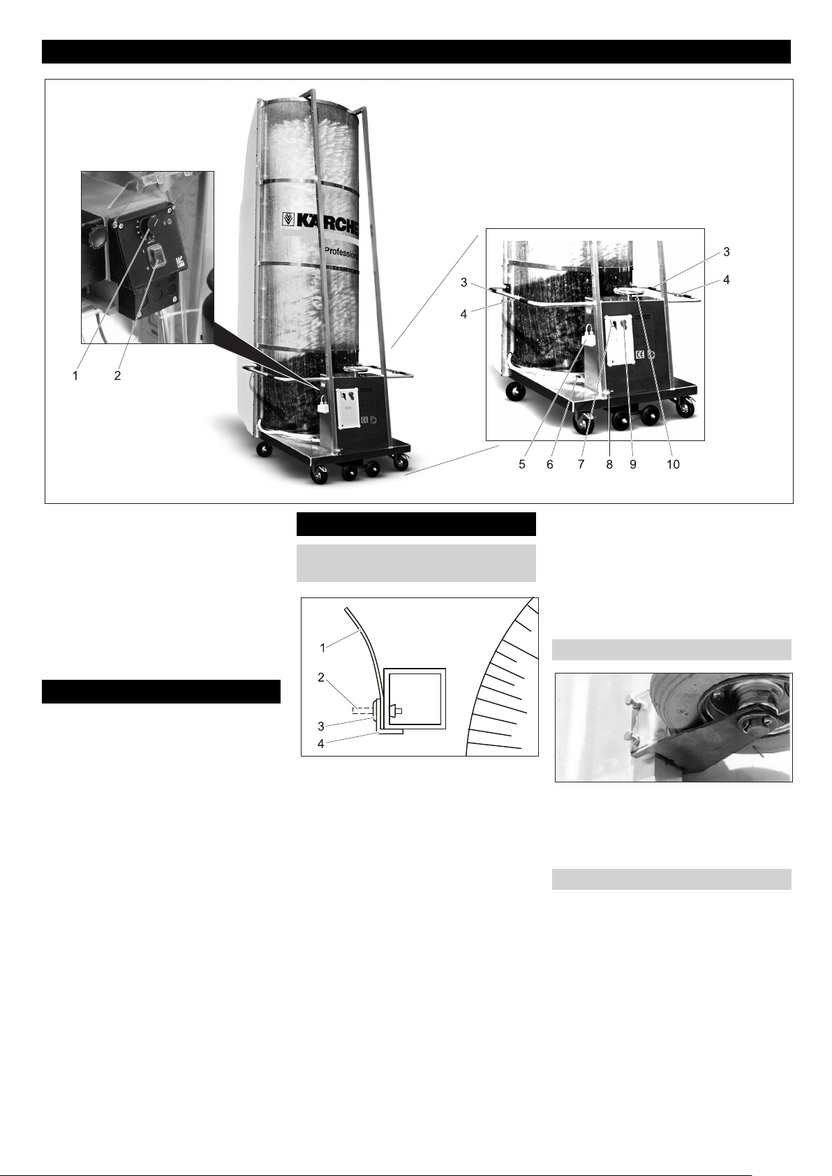
Eléments de commande
1 Bouton rotatif pompe de dosage*
2 Interrupteur pompe de dosage*
3 Poignée
4 Interrupteur de sécurité (brosse)
5 Fiche secteur
6 Vannes d'arrêt pour tubes de buse
7 Interrupteur principal
8 Arrivée d'eau
9 Touche d'arrêt d’urgence
10 Manivelle de position inclinée
Transport
몇 AVERTISSEMENT
Risque de blessure et d'endommagement !
Respecter le poids de l'installation lors du
transport.
L'installation peut être transportée couchée
sur le plan de chargement d'un camion :
Retirer les rouleaux d'écartement.
Basculer l'installation du côté brosse, à
l'aide d'une deuxième personne.
Pousser l'installation sur le plan de
chargement.
Protéger l'installation contre tout glisse-
ment.
Première mise en service
Mettre la protection contre les écla-
boussures en place
1 Protection contre les éclaboussures
2 Tige
3 Rivet écarteur
4 Profilé en équerre
Les deux profilés en équerre sont fixés
pour le transport à l'aide de rivets sur le bâti,
Repérer la position de montage des
profilés en équerre pour le montage.
Enfoncer les rivets avec un pointeau
vers l'intérieur.
Retirer les profilés en équerre.
Dérouler la protection ci-jointe contre
les éclaboussures et la poser sur le
tube carré.
Remarque :
Les bandes de protection contre les éclaboussures sont bombées dans le sens
court. Lors du montage, cette partie bombée de être dirigée à l'opposé de la brosse.
Remettre le profilé en équerre en place.
Enfoncer les rivets dans le profilé en
équerre, la protection contre les éclaboussures et le tube carré et bien les
fixer.
Enfoncer la cheville des rivets à l'aide
d'un marteau.
Répéter cette opération pour tous les
alésages dans les profilés en équerre.
Monter les rouleaux d'écartement
Fixer les deux rouleaux d'écartement
fournis sur le bâti de l'installation.
Sélectionner la hauteur en fonction des
véhicules à laver.
Serrer les contre-écrous.
Mettre la pompe de dosage en place
Dans le cas des installations suivantes,
une pompe de dosage ne fait pas partie de
la fourniture standard :
– 1.286-235.0
– 1.286-245.0
– 1.286-345.0
– 1.286-435.0
– 1.286-445.0
- 3
23FR
Page 24
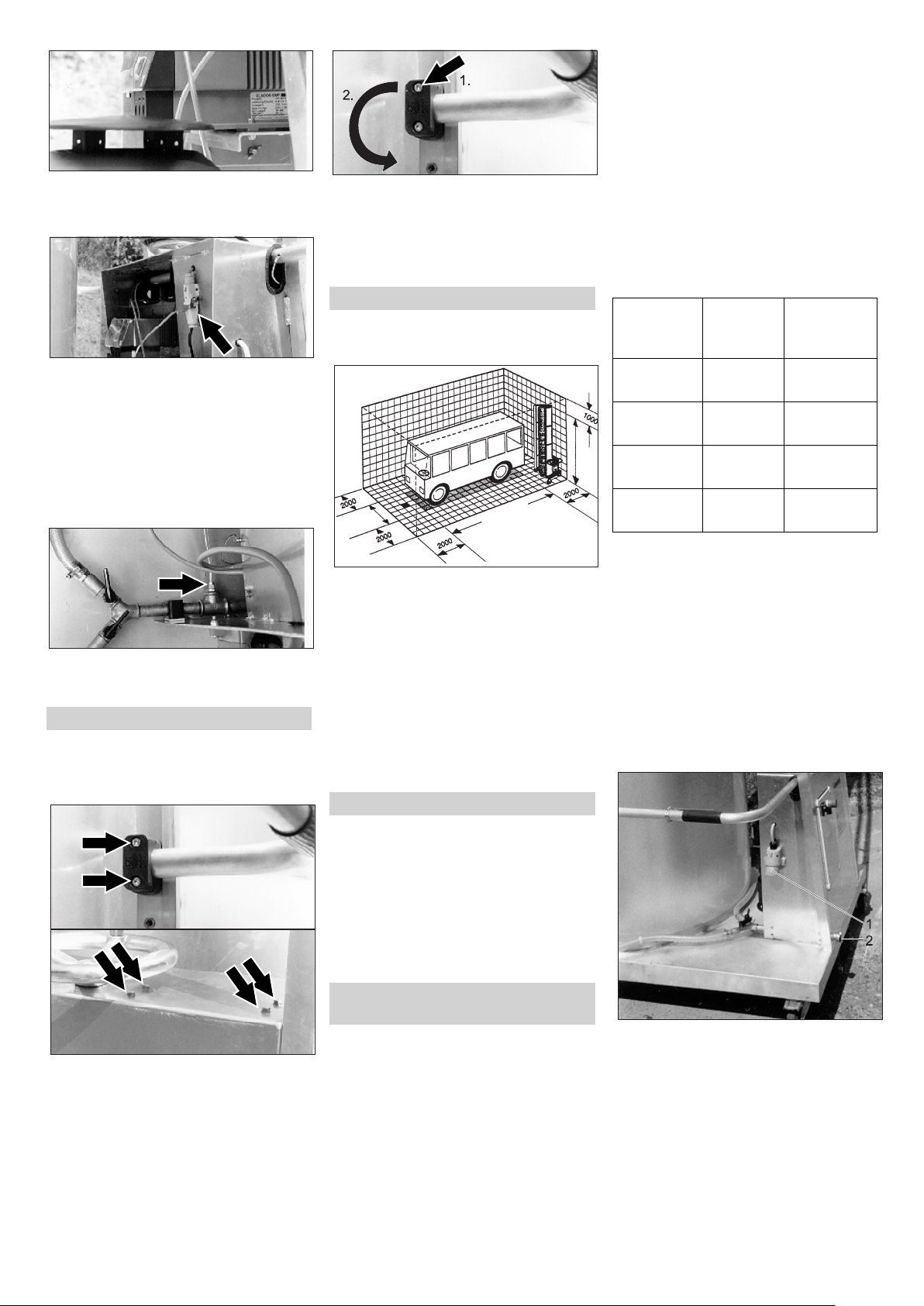
Fixer la pompe de dosage avec le ma-
tériel de montage fourni sur le bâti de
l'installation.
Enficher les câbles sur la pompe de do-
sage.
Remplir les bidons de détergent et les
poser sur la plaque de base de l'installation.
Plonger le flexible d'aspiration de la
pompe d'aspiration avec le filtre d'aspiration dans le bidon et visser le couvercle.
Insérer le flexible de la sortie de pompe
de dosage sur le raccord vissé du distributeur d'eau et serrer l'écrou-raccord.
Régler la poignée
Les poignées peuvent être fixée dans deux
positions.
Modifier la hauteur :
Retirer la vis extérieure du collier, tour-
ner le collier de 180° et revisser légèrement la vis
Pousser avec précaution la poignée
dans la nouvelle position et resserrer
les colliers.
Poste de lavage
L'installation peut être exploitée dans un
hall de lavage ou en pein-air.
Les dimensions nécessaires pour le poste
de lavage sont indiquées ci-dessus.
Exigences posées au poste de lavage :
– surface plane.
– aucun obstable
– pente de 2% au maximum
– Écoulement des eaux.
– grilles et tôles de recouvrement sur les-
quelle il est possible de marche de façon fiable.
– Revêtement de sol avec surface antidé-
rapante.
Arrivée d'eau
L'installation a besoin des câbles d'alimentation suivants :
– Câbles électriques conformes au ta-
bleau ci-après.
– Flexible d'eau de 3/4“.
La longueur correspondante du flexible
d'eau et du câble électrique dépend des
conditions locales ou de la longueur du véhicule.
Tous les quatre côtés du véhicule doivent
pouvoir être lavés en une passe, sans modification de l'installation.
Pour des raisons de sécurité, le câble électrique a une longueur limitée :
Raccordement électrique
400V, 3~, P,
N, 50 Hz
230V, 3~, P,
N, 60 Hz
230V, 1~, P,
N, 50 Hz
230V, 1~, P,
N, 50Hz
La longueur indiquée est mesurée de la sécurité en amont jusqu'à l'installation.
Si la longueur indiquée ne suffit pas,
s'adresser au fabricant de l'installation.
La version du raccord dépend du type d'utilisation.
– Si l'installation est utilisée sur différents
postes de lavage, le câble et le flexible
d'eau sont tirés sur le sol.
– Dans le cas d'une istallation fixe, l'ali-
mentation d'eau et de courant peut s'effectuer à partir du haut.
Gaine mobile sur le sol
Type de
câble
5 x 2,5 H07RN-F
5 x 2,5 H07RN-F
3 x 2,5 H07RN-F
3 x 1,5 H07RN-F
Longueur
maxi 100 m
maxi 58 m
maxi 100 m
maxi 60 m
몇 AVERTISSEMENT
La pollution du résau d'eau potable peut
porter préjudice à la santé.L'installation de
lavage ne doit pas être directement raccordée au réseau publique d'eau potable.
Lors du raccord au réseau d'eau potable,
un composant de sécurité doit être monté
entre le poste de lavage et le réseau d'eau
potable, conformément à EN 1717.
Mettre des câbles d'alimentation à
disposition
DANGER
Desserrer les vis.
Pivoter la poignée vers le bas pour ne
pas endommager le câble de l'interrupteur de sécurité.
Retirer avec précaution la poignée (le
câble de l'interrupteur de sécurité est
placé dans la poignée).
Tension électrique dangereuse. Seul un
électricien spécialisé est habilité à réaliser
l'installation électrique. En outre, il doit impérativement respecter les directives locales en vigueur.
Un interrupteur principal doit être monté
dans le câble d'alimentation électrique côté
client et doit pouvoir être protégé contre
toute mise en marche par inadvertance ou
non autorisée.
24 FR
1 Fiche secteur
2 Arrivée d'eau
Raccorder le flexible d'eau à l'arrivée
d'eau.
Connecter le câble électrique au sec-
teur.
- 4
Page 25
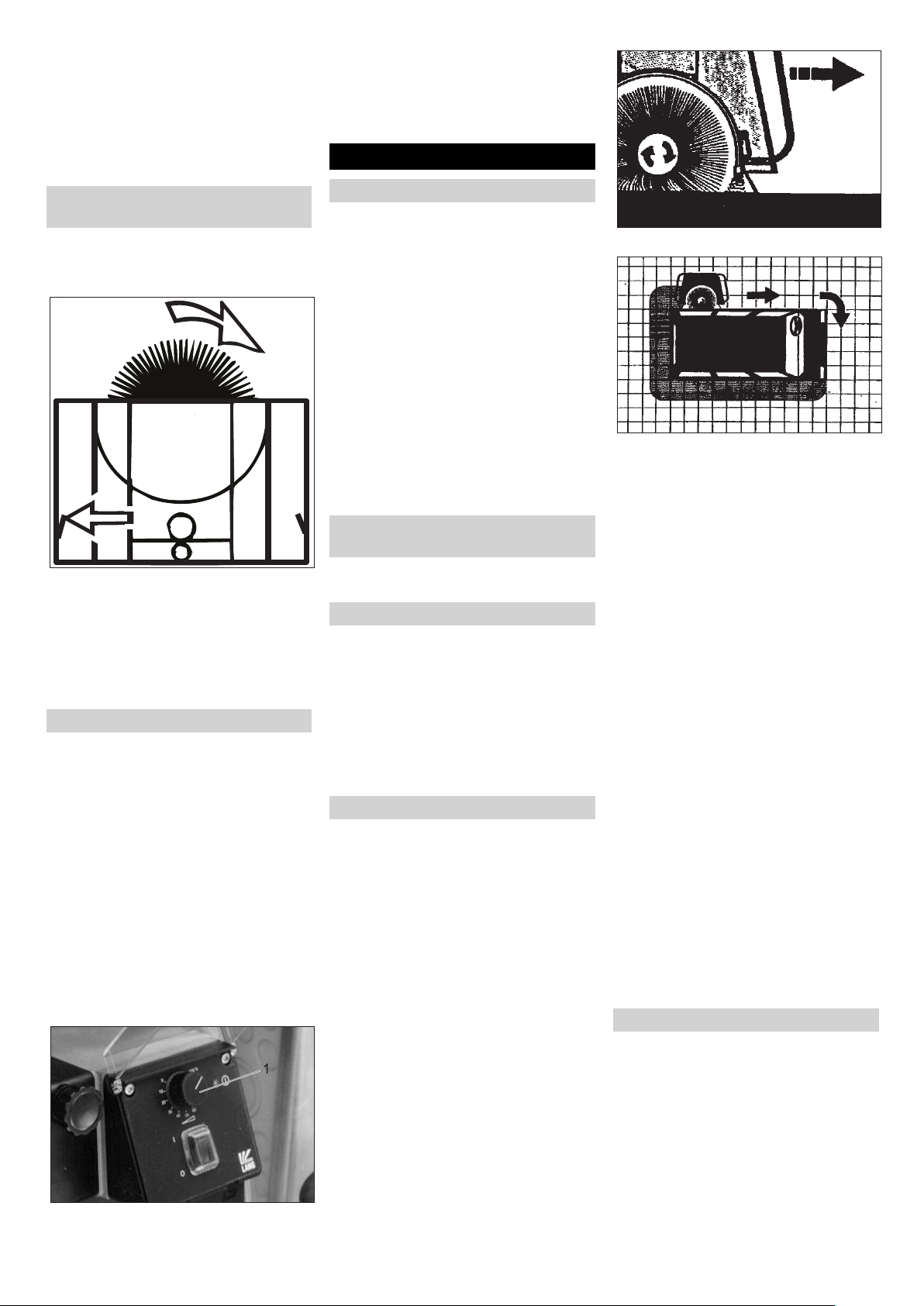
Gaine mobile au-dessus de la conduite
supérieure
Les câbles d'alimentation sont guidés vers
le premier chariot de conduites par un bras
de câbles réglable en hauteur.
Le raccord électrique et le raccord d'eau
sont installés de façon fixe et doivent être
effectués par un électricien qualifié.
Contrôler le sens de rotation de la
brosse
Lors du premier raccord de l'alimentation
en tension, il faut vérifier le sens de rotation
de la brosse.
Actionner l'interrupteur de sécurité re-
péré par une flèche dans la figure du
haut.
La brosse doit tourner dans le sens de
la flèche.
Si le sens de rotation est incorrect, faire
modifier le raccord électrique par un
électricien qualifié.
Réglage de la pompe de dosage
Dans le cas des installations suivantes,
une pompe de dosage ne fait pas partie de
la fourniture standard :
– 1.286-235.0
– 1.286-245.0
– 1.286-345.0
– 1.286-435.0
– 1.286-445.0
Remarque :
Le débit de dosage est réglé de façon optimale en usine. Un nouveau réglage n'est
en règle générale pas nécessaire.
PRÉCAUTION
La pompe de dosage risque d'être endommagée. N'actionner le bouton rotatif que
lorsque la pompe fonctionne.
1 Bouton de réglage
Tourner le bouton rotatif sur le débit de
dosage voulu pendant que la pompe de
dosage fonctionne.
Les pourcentages indiqués sur la pompe
de dosage se réfèrent à la puissance maxi
de la pompe.
Fonctionnement
Avant chaque mise en service
Retirer tout obstacle et objet traînant du
poste de lavage.
Établir le raccord d'eau.
Établir le raccord électrique.
Vérifier le niveau du réservoir de dé-
tergent et faire l'appoint en cas de besoin.
DANGER
Risque de chute dû aux objets ou câbles
traînant sur le sol.
Retirer les objets traînant dans le poste
de lavage, avant de mettre l'installation
en place.
Lors de l'utilisation de l'installation avec
gaine mobile sur le sol, veiller à ce que
les câbles d'alimentation soient bien
guidés.
Comportement à adopter en cas
d'urgence
En cas d'urgence, relâcher l'interrup-
teur de sécurité de la brosse.
Préparer le véhicule
Fermer les fenêtres, les portes et les lu-
carnes.
Retirer les rétroviseurs latéraux ou les
rabattre.
Rentrer ou retirer les antennes.
Retirer ou freiner les pièces non atta-
chées (filins de bâches, etc.).
Fermer les bâches et les fixer de façon
fiable.
Utilisation
Stationner le véhicule au centre du
poste de lavage ou sous la gaine mobile.
Régler l'installation avec la manivelle
de réglage oblique sur l'inclinaison de la
surface à nettoyer.
Positionner l'installation au début d'un
côté longitudinal du véhicule.
Ouvrir la vanne d'arrêt pour le tube de
buse se trouvant dans le sens du lavage
Mettre le commutateur principal sous
tension.
Enclencher la pompe de dosage.
Retenir l'installation des deux mains au
niveau de la poignée se trouvant dans
le sens du lavage.
PRÉCAUTION
Risque d'endommagement. Ne pas modifier le sens de rotation pendant le fonctionnement de la brosse.
Enclencher la brosse en tirant l'interrup-
teur de sécurité de la brosse au niveau
de la poignée correspondante.
Profondeur de pénétration de la brosse
Sens du lavage
Déplacer l'installation à la même vi-
tesse sur le véhicule, en la tirant au niveau de la poignée.
Remarque :
Toujouts tirer l'installation.
Le sens de rotation de la brosse est choisi
de manière à ne réclamer qu'un minimum
de déploiement de forces.
Lorsque la force d'appui appliquée est correcte, les rouleaux d'écartement touchent
légèrement le véhicule.
Une pression d'application trop importante
n'améliore pas le résultat du nettoyage.
Lorsque les rétroviseurs sont fixes et ne
peuvent pas être rentrés, l'installation doit
être légèrement écartée du véhicule.
Orienter l'installation au niveau des
coins du véhicule, parfaire éventuellement le réglage de l'inclinaison et poursuivre le lavage.
PRÉCAUTION
Risque d'endommagement pour le câble
d'alimentation, dû à la torsion. Changer le
sens de lavage après chaque contour du
véhicule.
Lorsque tous les côtés du véhicule sont
lavés :
Couper la pompe de dosage.
Modifier l'arrivée d'eau sur un autre dia-
mètre de tuyau.
Pour le rinçage, contourner une nou-
velle fois le véhicule dans le sens inverse.
Achever le lavage
Écarter l'installation de lavage du véhi-
cule.
Relâcher l'interrupteur de sécurité de la
brosse.
Couper la pompe de dosage.
Couper l'alimentation en eau.
En cas de pauses d'exploitation de plus
longue durée:
Tourner le sectionneur général sur la
position "0".
Le cas échéant, mettre le câble d'ali-
mentation hors tension.
- 5
25FR
Page 26
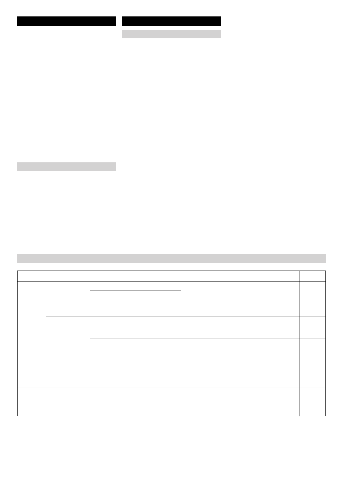
Entreposage
AVERTISSEMENT
몇
Risque de blessure et d'endommagement !
Respecter le poids de l'installation lors du
stockage.
Pousser l'installation vers l'emplace-
ment de repos.
Dans le cas d'une gaine mobile, retirer
éventuellement les câbles de raccord
sur le sol.
Si le poste se trouve en plein air et ou-
vert, placer l'installation à l'abri du vent
ou la protéger contre la chute à l'aide
d'un filin ou d'une chaîne.
Serrer les freins d'arrêt au niveau des
rouleaux.
DANGER
Risque de blessure en cas de renversement de l'installation. Installer l'installation
à l'abri du vent et la freiner contre le renversement.
Protection antigel
Protéger les pièces aquifères de l'installation du fel, puisque autrement ils sont détruites.
En cas de gel, l'installation doit être intégralement vidangée :
Couper l'alimentation en eau.
Passer la conduite d'alimentation
(flexible d'eau) et l'installation à l'air
comprimé.
Enclencher l'entraînement de brosse
pour permettre à l'eau de s'éjecter hors
de la brosse.
Entretien et maintenance
Consignes pour la maintenance
La maintenance régulière selon le plan de
maintenance suivant est primordial pour
assurer un fonctionnement fiable de la station de lavage.
Utiliser uniquement des pièces de rechange d'origine du fabricant ou bien des
pièces recommandées telles que
– les pièces de rechange et d'usure
– les accessoires
– les carburants
– Produit détergent
DANGER
Risque d'électrocution.
Commuter la station de lavage hors tension
en réglant l'interrupteur principal de la station sur « 0 » et en la protégeant contre
toute remise en marche.
Risque de blessures des yeux par des
pièces ou de la saleté. Ne pas se tenir à
proximité des brosses rotatives. Toujours
porter des lunettes de protection pour effectuer des travaux de maintenance.
Qui a le droit d'effectuer des travaux
d'inspection, de maintenance et de remise en état ?
Exploitant
Les travaux associés à la remarque
« Exploitant » doivent être effectués exclusivement par du personnel qualifié, capable d'utiliser et d'entretenir correctement
les installations de lavage.
Service après-vente
Les travaux associés à la remarque "Service après-vente" doivent être exclusivement effectués par les monteurs du service
après-vente Kärcher.
Contrat de maintenance
Nous vous recommandons de conclure un
contrat de maintenance afin de pouvoir assurer un fonctionnement fiable de la station
de lavage. Veuillez vous adresser à votre
service après-vente Kärcher responsable.
Plan de maintenance
Période Action Sous-groupe concerné Remède Par qui
mensuellement
Tous les
trimestres
Graissage Palier de brosse Graisser le graisseur avec une presse à graisser.
Palier broche de réglage incliné
Chaîne Graisse 6.288-059.0, appliquer au pinceau. Opéra-
Contrôle visuel Roulettes pivotantes En vérifier la mobilité, l'huiler si nécessaire.
Buses dans le porte-buses. Contôler le cône de vaporisation des buses.
Filtre d'aspiration du détergent Eliminer les dépôts. Opéra-
Gaine mobile (option) Vérifier si les conduites sont en bon état et
Contrôle visuel Brosses Vérifier la bonne assise des segments et des
Graisse 6.288-059.0
Vérifier le frein d'arrêt, le remettre en état si nécessaire ou remplacer le galet de guidage
Nettoyer les buses si nécessaire.
exemptes de torsion.
agrafes finales. Vérifier la propreté et l'état des
brosses. Le diamètre de brosse doit être supérieur
à 870 mm.
Opérateur
teur
Opérateur
Opérateur
teur
Opérateur
Opérateur
26 FR
- 6
Page 27
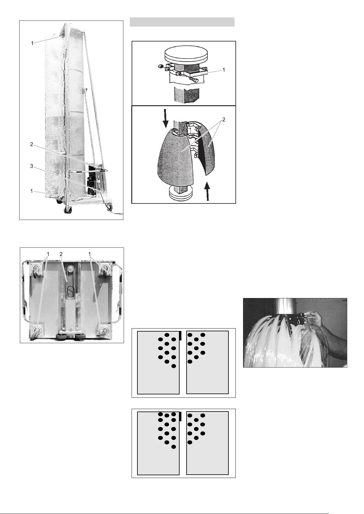
1 Palier de brosse
2 Manivelle de position inclinée
3 Palier broche de réglage incliné
Remplacement de brosse
Arbre à quatre pans avec demi-coques
1 Agrafe
2 Demi-coque de brosse
DANGER
Risque d'accident lors des travaux sur l'appareil !
Avant commencer les travaux à l'installation, éteindre et protéger l'interrupteur principal.
Dévisser les vis de l'agrafe finale et re-
tirer l'agrafe finale.
Décaler les demi-coques de brosse
l'une contre l'autre et les retirer de
l'arbre de brosse.
Monter les nouvelles demi-coques de la
manière suivante.
몇 AVERTISSEMENT
Risque d'accident ! Deux types différents
sont utilisés pour les demi-coques et ne
doivent être mélangés en aucun cas. Sinon, les demi-coques risquent de se détacher de l'arbre pendant l'exploitation. Les
deux types diffèrent par la disposition des
touffes au début et à la fin de la demicoque. Respecter ce qui suit, afin d'éviter
un balourd et d'éventuels endommagements consécutifs : Les demi-coques
doivent toujours être remplacées par
paires, donc toujours en tant que segment
complet. Les touffes de poils le long du joint
des demi-coques doivent toujours être décalées les unes par rapport aux autres.
Poser la première paire de demi-
coques sur l'arbre et l'assembler.
Poser la deuxième paire de demi-
coques avec un décalage de 90° et l'assembler.
Poser d'autres paires de demi-coques
chacune avec un décalage de 90° sur
l'arbre.
À l'issue du montage de la dernière
paire de demi-coques, mettre l'agrafe finale en place.
Pousser l'agrafe finale contre la der-
nière demi-paire de coques et serrer les
vis.
Vérifier une nouvelle fois le montage
correct des demi-coques et le bon serrage des vis.
Arbre rond avec brosse de tapis
DANGER
Risque d'accident lors des travaux sur l'appareil !
Avant commencer les travaux à l'installation, éteindre et protéger l'interrupteur principal.
1 Roues directionnelles
2 Chaîne
Demi-coques de brosses type 1
Demi-coques de brosses type 2
- 7
Desserrer les vis d'un segment de tapis
et retirer le segment de tapis.
Retirer d'autres segments de tapis les
uns après les autres.
Monter le premier segment de tapis
neuf dans les trous prévus à cet effet.
Monter chaque segment de tapis sui-
vant à 180° par rapport au précédent.
Une fois le montage terminé, vérifier la
bonne assise des segments de tapis et
le bon serrage des vis.
27FR
Page 28
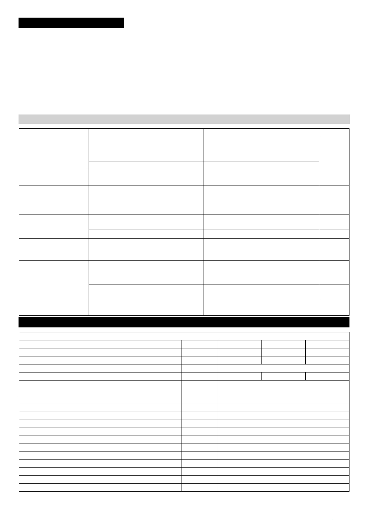
Service de dépannage
DANGER
Risque d'électrocution.
Seuls des électriciens ont le droit d'exécuter des travaux sur l'installation électrique.
Commuter la station de lavage hors tension
avant d'effectuer tout type de travaux. Pour
ce faire, commuter l'interrupteur principal
de la station en position '0' et la protéger
contre une remise en marche.
Qui a le droit d'éliminer des pannes ?
Exploitant
Des travaux avec la remarque 'Exploitant'
doivent uniquement être effectués par des
personnes instruites et en mesure de manier et d'entretenir correctement la station
de lavage.
Electriciens
Personnes avec une formation professionnelle dans le domaine électrotechnique.
Service après-vente
Des travaux avec la remarque 'Service
après-vente' doivent uniquement être effectués par des monteurs du service aprèsvente Kärcher ou par des monteurs mandatés par Kärcher.
DANGER
Risque d'électrocution.
Commuter la station de lavage hors tension
en réglant l'interrupteur principal de la station sur « 0 » et en la protégeant contre
toute remise en marche.
Risque de blessures des yeux par des
pièces ou de la saleté. Ne pas se tenir à
proximité des brosses rotatives. Toujours
porter des lunettes de protection pour effectuer des travaux de maintenance.
Pannes
Erreur Eventuelle cause Remède Par qui
L'installation ne démarre
pas
La brosse n'atteint pas la
vitesse voulue
Malgré une purge et la
quantité de dosage maxi,
la pompe de dosage n'aspire pas
La pompe de dosage aspire de l'air
Manque d'étanchéité des
pompes de la pompe de
dosage
La pompe de dosage ne
travaille pas, le témoin de
contrôle n'est pas allumé.
Cône de vaporisation irrégulier des buses
Pas de courant Contrôler le réseau électrique. ÉlectriFusible défaillant. Réparer la cause.
cien
Remplacer le fusible.
Le disjoncteur-protecteur a déclenché. Vérifier la consommation de courant.
Palier grippé. Vérifier le palier de brosse. Opérateur
Dépôts sur les sièges de vannes, vannes
grippées.
Manque d'étanchéité de la vanne d'aspiration
ou de la vanne de pression.
Rincer les conduites d'aspiration et les
vannes.
Vérifier l'étanchéité des vannes et conduites
d'aspiration.
Opérateur
Opérateur
Tête de pompe pas serrée. Serrer les vis de la tête de pompe. Opérateur
Tête de pompe pas serrée.
Rupture du ressort de membrane.
Pas de courant Vérifier et mettre en route l'approvisionne-
Serrer les vis de la tête de pompe.
Remplacer la membrane.
Opérateur
Opérateur
ment électrique.
Fusible défaillant. Remplacer le fusible. Opérateur
Platine défaillante. Remplacer la platine. Électri-
cien
Les buses sont bouchées. Nettoyer les buses. Opérateur
Caractéristiques techniques
Dimensions de la station de lavage
RBS 6012 RBS 6013 RBS 6014
Hauteur de l'installation mm 3180 4090 4370
Hauteur de lavage mm 3645 3925 4205
Largeur de l'installation mm 1700
Poids kg 234 237 240
Encombrement du poste de lavage mm Longueur du véhicule +4000
Largeur du véhicule + 4000
Pression d'écoulement d'eau MPa (bars) 0,3...0,6 (3...6)
Arrivée d'eau Pouces 3/4
Consommation d'eau, env. l/min 80
Température d'eau max. °C 30
Puissance absorbée kW 1,1
Type de protection IP54 IP45
Température ambiante °C +3...+50
Humidité, max. % 70
Niveau de pression acoustique L
Incertitude K
pA
pA
Valeur totale d'oscillation des bras m/s
Incertitude K m/s
dB(A) 65
dB(A) 4
2
2
<2,5
0,1
28 FR
- 8
Page 29
Contenu de livraison
Sommaire Dimensions Poids
en vrac Installation RBS 4500mm x 1700 mm x 1100 mm 250 kg
Carton Accessoires de
l'installation
Versions de l'installation
Numéro de
pièce
1.826-205.0 400 V, 3~, P, N, 50 Hz
1.826-215.0 230 V, 3~, P, N, 50 Hz
1.826-225.0 240 V, 1~, P, N, 50 Hz
1.826-235.0 400 V, 3~, P, N, 50 Hz
1.826-245.0 400 V, 3~, P, N, 50 Hz
1.826-801.0 400 V, 3~, P, N, 50 Hz
1.826-802.0 230 V, 3~, P, N, 50 Hz
1.826-803.0 240 V, 1~, P, N, 50 Hz
RBS 6012
1.826-345.0 400 V, 3~, P, N, 50 Hz
RBS 6013
1.862-405.0 400 V, 3~, P, N, 50 Hz
1.862-415.0 230 V, 3~, P, N, 50 Hz
1.862-425.0 240 V, 1~, P, N, 50 Hz
1.862-435.0 400 V, 3~, P, N, 50 Hz
1.862-445.0 400 V, 3~, P, N, 50 Hz
1.862-455.0 230 V, 3~, P, N, 60 Hz
1.862-804.0 400 V, 3~, P, N, 50 Hz
1.862-805.0 230 V, 3~, P, N, 50 Hz
1.862-806.0 240 V, 1~, P, N, 50 Hz
RBS 6014
Tension
Accessoires
Produit détergent
RM 811
Dosage :
400 mm x 350 mm x 350 mm 5 kg
Déclaration UE de conformité
Nous certifions par la présente que la machine spécifiée ci-après répond de par sa
conception et son type de construction ainsi que de par la version que nous avons
mise sur le marché aux prescriptions fondamentales stipulées en matière de sécurité et d’hygiène par les directives
européennes en vigueur. Toute modification apportée à la machine sans notre accord rend cette déclaration invalide.
Produit : Installation de lavage
Type : 1.826-xxx
Directives européennes en vigueur :
2006/42/CE (+2009/127/CE)
2014/30/UE
Normes harmonisées appliquées :
EN 60204–1
EN 61000–6–3: 2007 + A1:2011
EN 61000–6–2: 2005
Normes nationales appliquées :
Les signataires agissent sous ordre et avec
le pouvoir de la direction.
Chairman of the Board of Management
Responsable de la documentation :
S. Reiser
Alfred Kärcher SE & Co. KG
Alfred-Kärcher-Straße 28-40
71364 Winnenden (Germany)
Tel.: +49 7195 14-0
Fax: +49 7195 14-2212
Director Regulatory Affairs & Certification
Dans chaque pays, les conditions de garantie en vigueur sont celles publiées par
notre société de distribution responsable.
Les éventuelles pannes sur les accessoires sont réparées gratuitement dans le
délai de validité de la garantie, dans la mesure où celles-ci relèvent d'un défaut matériel ou d'un vice de fabrication. En cas de
recours en garantie, adressez-vous à votre
revendeur ou au service après-vente agréé
le plus proche munis de votre preuve
d'achat.
Pièces de rechange
– Utiliser uniquement des accessoires et
des pièces de rechange autorisés par le
fabricant. Des accessoires et des
pièces de rechange d’origine garantissent un fonctionnement sûr et parfait
de l’appareil.
– Une sélection des pièces de rechange
utilisées le plus se trouve à la fin du
mode d'emploi.
– Vous trouverez plus d'informations sur
les pièces de rechange dans le menu
Service du site www.kaercher.com.
Garantie
Installation avec
pompe de dosage
0...5 l/h (0...80ml/min)
Installation avec
pompe de dosage
0..0,15 l/h (0..0,250
ml/min)
env. 100 % correspond à 80 ml/
min
32...64 % correspond à 80...160
ml/min
Jeux de montage
Kit de montage pompe de dosage
Référence 3.637-162.0
Réservoir
500 l, référence 3.070-010.0
1000 l, référence 3.070-011.0
Soupape à flotteur
Référence 6 412-765.0
Installation d'augmentation de pression
Référence 6 473-165.0
Kit de montage séparateur de tuyau
Référence 2 637-650.0
Winnenden, le 01/01/2019
- 9
29FR
Page 30

Prima di utilizzare l'apparecchio
per la prima volta, leggere le
presenti istruzioni originali, seguirle e conservarle per un uso futuro o in caso di rivendita dell'apparecchio.
Indice
Protezione dell’ambiente . . IT . . 1
Simboli riportati nel manuale
d'uso . . . . . . . . . . . . . . . . . . IT . . 1
Norme di sicurezza . . . . . . . IT . . 1
Dispositivi di comando . . . . IT . . 3
Trasporto. . . . . . . . . . . . . . . IT . . 3
Prima messa in funzione . . IT . . 3
Funzionamento . . . . . . . . . . IT . . 5
Supporto . . . . . . . . . . . . . . . IT . . 6
Cura e manutenzione . . . . . IT . . 6
Risoluzione guasti. . . . . . . . IT . . 8
Dati tecnici . . . . . . . . . . . . . IT . . 8
Accessori . . . . . . . . . . . . . . IT . . 9
Dichiarazione di conformità UE IT . . 9
Garanzia . . . . . . . . . . . . . . . IT . . 9
Ricambi. . . . . . . . . . . . . . . . IT . . 9
Protezione dell’ambiente
I materiali dell’imballaggio
sono riciclabili. Non smaltire
l’imballaggio con i rifiuti domestici, ma conferirlo al riciclaggio.
Gli apparecchi usati contengono materiali riciclabili preziosi,
che dovrebbero pertanto essere conferiti al riciclaggio per assicurare il loro riutilizzo.
Batterie, olio e sostanze simili
non devono essere dispersi
nell’ambiente. Smaltire pertanto gli apparecchi usati attraverso idonei centri di raccolta.
L'olio riduttore non deve essere disperso
nell'ambiente. Si prega pertanto di proteggere il terreno e di smaltire l'olio usato comformemente alle norme ambientali.
Solo dopo aver trattato le acque di scarico
sporche d'olio è possibile immetterle nel
sottosuolo, nelle acque superficiali e negli
impianti di canalizzazione. Osservare le
norme e le leggi vigenti.
Avvertenze sui contenuti (REACH)
Informazioni aggiornate sui contenuti sono
disponibili all'indirizzo:
www.kaercher.com/REACH
Simboli riportati nel manuale
d'uso
PERICOLO
Per un rischio imminente che determina lesioni gravi o la morte.
몇 AVVERTIMENTO
Per una situazione di rischio possibile che
potrebbe determinare lesioni gravi o la
morte.
PRUDENZA
Per una situazione di rischio possibile che
potrebbe determinare danni leggeri a persone o cose.
Norme di sicurezza
Norme di sicurezza
Norme generali
Per evitare pericoli per le persone, per gli
animali e le cose, si prega di leggere quanto segue prima di utilizzare l'impianto per la
prima volta:
– il manuale d'uso
– tutte le norme di sicurezza
– le disposizioni di legge vigenti a livello
nazionale
– gli avvisi di sicurezza allegati ai deter-
genti utilizzati (normalmente si trovano
sull'etichetta della confezione).
Nella Repubblica Federale Tedesca l'esercizio di questo impianto è regolamentato
dalle disposizioni e le direttive di seguito indicate (le relative documentazioni sono reperibili presso la casa editrice Carl
Heymanns Verlag KG, Luxemburger
Straße 449, 50939 Colonia):
– norme antinfortunistiche "Disposizioni
generali" BGV A1
– Regolamento tedesco sulla sicurezza
nelle imprese (BetrSichV).
Assicurarsi:
– di aver capito tutte le norme ed avver-
tenze
– che tutti gli utilizzatori dell'impianto sia-
no informati sulle norme ed avvertenze
e che le abbiano capite.
Le presenti istruzioni per l'uso devono essere convertite dal gestore dell'autolavaggio in istruzioni operative nel rispetto delle
circostanze locali e personali. La presenza
delle istruzioni per l'uso deve essere resa
nota in maniera adatta esponendola sul posto di lavoro.
Impianti di lavaggio macchine
Solo coloro che hanno letto le istruzioni e
che sono al corrente dei rischi legati alla
messa in funzione dell'impianto devono ricevere l'incarico di occuparsi del funzionamento, della supervisione, della cura,
dell'assistenza e dell'ispezione dello stesso.
Self service
Dagli autolavaggi con funzionamento in self
service, durante gli orari di apertura deve essere sempre reperibile una persona che conosca l'impianto e che, in caso di guasto,
possa provvedere ad adottare tutte le misure
necessarie a prevenire eventuali pericoli.
L'impianto deve disporre di cartelli ben leggibili con indicazione delle istruzioni per l'utilizzatore e dell'uso conforme a destinazione.
Riparazione
Qualsiasi intervento di riparazione va effettuato esclusivamente ad impianto spento.
L'interruttore principale va bloccato in maniera da non poter essere riattivato dai non
autorizzati.
Sostanze pericolose
In caso di uso di concentrati detergenti che
contengono sostanze nocive per la salute,
adottare le debite misure di protezione. In
particolare, indossare occhiali, guanti e indumenti protettivi e osservare le istruzioni/
schede dati di sicurezza dei prodotto detergente.
Accesso all'impianto di autolavaggio
L'accesso all'impianto a persone non autorizzate va vietato. Il divieto d'accesso va
segnalato in maniera ben riconoscibile e
duratura.
Pericolo di scivolamento
All'interno dell'impianto c'è pericolo di scivolare sul pavimento e su componenti bagnati. Durante i lavori sull'impianto si
raccomanda di muoversi con cautela ed indossare delle scarpe adatte. Avvertire i
clienti del pericolo di scivolamento con appositi cartelli.
Uso dell'impianto
몇 AVVERTIMENTO
Per evitare che l'impianto venga usato in
modo improprio, deve essere usato solo da
persone che
– sanno come utilizzarlo
– hanno dimostrato di avere le capacità di
utilizzarlo
– sono stati formalmente incaricati di uti-
lizzarlo.
Le istruzioni per la messa in funzione devono essere accessibili a tutti gli utenti. L'impianto non deve essere utilizzato da
persone minori di 18 anni. Da questo provvedimento sono esclusi gli apprendisti minori di 16 anni sotto diretto controllo.
Uso conforme a destinazione
Lo RBS 6000 è destinato per il lavaggio a
spazzola di pullman e furgoni, camion, camion con rimorchi e semirimorchi. L'inclinazione delle pareti laterali dei veicoli deve
essere minore di 10 gradi.
L'impianto può essere fatto funzionare in
un capannone di lavaggio o all'aperto.
L'uso conforme comprende anche:
– il rispetto di tutte le indicazioni contenu-
te nel presente manuale
– l'osservanza degli avvisi di ispezione e
di manutenzione.
PRUDENZA
Maggiore pericolo di corrosione a causa
dell'uso di detergenti inadatti.
I seguenti detergenti non devono essere
trattati dall'impianto:
– Detergenti indicati per la pulizia dello
stabilimento di lavaggio.
– Detergenti indicati per la pulizia esterna
dell'impianto di lavaggio.
– Detergenti alimentati sul veicoli con un
apparecchio a parte (ad es. lavacerchioni).
– Mezzi per il trattamento delle acque di
scarico.
Usare solo detergenti autorizzati dalla ditta
KÄRCHER.
Postazione di lavoro
L'impianto viene tenuto all'impugnatura con
tutte e due le mani e tirato lungo il veicolo.
Durante ciò con una mano bisogna azionare l'interruttore di sicurezza Spazzola.
30 IT
- 1
Page 31

Uso improprio
PRUDENZA
Rischio di danneggiamento! Lo RBS 6000
è adatto solo per la pulizia di veicoli con pareti laterali lisce e dritte, dove la loro inclinazione è minore di 10°.
Il gestore dell'impianto è responsabile per
tutti i danni che si creano con impieghi eseguiti non a regola d'arte, in particolare lavando veicoli che non sono descritti nelle
presenti istruzioni.
Fonti di pericolo
Pericoli generali
PERICOLO
Le fughe di pressione possono provocare
danni agli occhi. La parti pneumatiche
dell'impianto rimangono sotto pressione
anche dopo l'esclusione dell'interruttore
principale o di quella dell'interruttore
d'emergenza.
Le parti mobili possono essere potenzialmente pericolose! I frammenti o gli oggetti
volanti possono ferire persone o animali.
Perciò il terreno deve essere libero da oggetti caduti per terra.
Rischio di esplosioni
PERICOLO
Rischio di esplosione! È vietato l'esercizio
dell'impianto in locali a rischio d'esplosione.Ne sono esclusi solo gli impianti concepiti appositamente per tale uso e
contrassegnati di conseguenza.È vietato
usare come detergenti sostanze esplosive,
altamente infiammabili o velenose, come
ad esempio:
– benzina
– gasolio e carburante diesel
– solventi
– liquidi contenenti solventi
– acidi allo stato puro
– acetone
In caso di dubbio si prega di consultare il
costruttore.
Danni all'udito
I rumori emessi dall'impianto non sono pericolosi. Tuttavia il rumore non assorbito
generato da vari componenti/corpi può provocare il cosiddetto "Pericolo Rumori". In
tal caso si prega di indossare i dispositivi di
protezione per le orecchie.
Pericoli di tipo elettrico
PERICOLO
Pericolo di scosse elettriche.
– Non toccare mai con le mani bagnate i
cavi elettrici, i collegamenti a spina e le
scatole dei morsetti.
– Non danneggiare i cavi elettrici o i cavi
prolunga passandoci sopra, schiacciandoli o tirandoli. Proteggere i cavi
contro il caldo eccessivo, il contatto con
l'olio e gli spigoli vivi.
– Non puntare mai il getto d'acqua di ap-
parecchi di pulizia mobili (p.es. idropulitrici) su apparecchiature elettriche o
impianti elettrici.
– Tutti i componenti conduttori nell'area di
lavoro devono essere protetti contro i
getti di acqua.
– Gli impianti vanno collegati solo a sor-
genti di corrente collegate correttamente a terra.
– Qualsiasi intervento sui componenti
elettrici dell'impianto va eseguito esclusivamente da un elettricista specializzato.
– Gli accessori che non sono collegati di-
rettamente all'impianto devono essere
integrati nella compensazione del potenziale.
Pericolo da sostanze nocive
PERICOLO
I detergenti utilizzati contengono in parte
sostanze nocive per la salute; osservare
pertanto le indicazioni allegate o stampate
sulla confezione del detergente.
È vietato bere l'acqua dell'impianto! A causa dei detergenti aggiunti l'acqua non è di
qualità potabile.
Nel caso in cui venga utilizzata acqua riciclata trattata per l'esercizio dell'impianto,
osservare le disposizioni del costruttore
dell'impianto di trattamento acqua relative
all'inibizione della germinazione.
Non devono giungere nell'impianto tutte
quelle sostanze non generalmente comuni
alla pulizia esterna di veicoli (p.es. sostanze chimiche, metalli pesanti, pesticidi, sostanze radioattive, feci o sostanze
inquinanti).
Pericolo di abbassamento di corrente
Grazie alle misure costruttive è da escludersi una riaccensione incontrollata dell'impianto dopo un'abbassamento di corrente
La spazzola ruota solo con l'azionamento
di un interruttore di sicurezza.
Le acque di scarico rappresentano una
minaccia per l'ambiente
Osservare le leggi vigenti sul rispetto
dell'ambiente.
Manutenzione e sorveglianza
Per garantire il funzionamento sicuro
dell'impianto ed evitare rischi durante la
manutenzione, la sorveglianza e l'omologazione bisogna osservare le disposizioni
corrispondenti.
Riparazione
I lavori di manutenzione vanno effettuati da
personale esperto ad intervalli regolari in
conformità alle indicazioni del costruttore e
nel rispetto delle disposizioni e delle norme
di sicurezza vigenti. Gli interventi sull'impianto elettrico vanno eseguiti esclusivamente da un elettricista specializzato.
PERICOLO
Rischio di lesioni. Prima di effettuare lavori
di manutenzione e di riparazione, spegnere
l'impianto e bloccarlo contro una riaccensione involontaria o abusiva.
Controlli
Questo impianto di autolavaggio va controllato, prima della prima messa in funzione e
in seguito ogni sei mesi, da personale
esperto che dovrà verificarne il funzionamento sicuro. Tale controllo include in particolare:
– controllo visivo di eventuali segni di
usura e danni visibili dall'esterno
– Controllo del funzionamento
– verifica dell'integrità e del corretto fun-
zionamento dei dispositivi di sicurezza
(dagli impianti in self service ogni giorno
prima dell'avvio dell'impianto, dagli impianti sorvegliati quando necessario,
ma almeno una volta al mese).
Utilizzo di pezzi originali
Utilizzare esclusivamente i prodotti e i ricambi originali del costruttore o da esso
raccomandati; in caso contrario vengono
invalidati i diritti di garanzia. Si prega di osservare tutte le norme di sicurezza e le
istruzioni d'uso allegate a questi prodotti e
ricambi. Ciò vale per:
– pezzi di ricambio e pezzi soggetti ad
usura
– accessori
– carburante e sostanze aggiuntive
– detergenti.
Pulsante di arresto d'emergenza
PERICOLO
Pericolo di incidenti a causa di dispositivi di
sicurezza difettosi! L'impianto è dotato di
un pulsante di arresto d'emergenza e di
due „Interruttori di sicurezza Spazzola“.
I dispositivi di sicurezza vanno controllati
sul loro funzionamento regolare secondo
necessità, però almeno una volta il mese!
- 2
31IT
Page 32

Dispositivi di comando
1 Manopola pompa di dosaggio*
2 Interruttore pompa di dosaggio*
3 Impugnatura
4 Interruttore di sicurezza (spazzola)
5 Spina di alimentazione
6 Valvole di chiusura per tubi spruzzatori
7 Interruttore principale
8 Collegamento idrico
9 Pulsante d'arresto d'emergenza
10 Manovella per inclinazione
Trasporto
몇 AVVERTIMENTO
Pericolo di lesioni e di danneggiamento! Rispettare il peso dell'impianto durante il trasporto.
L'impianto può essere trasportato in orizzontale su un pianale di carico di un camion:
Rimuovere le rotelle distanziatrici.
Ribaltare l'impianto con due persone
sul lato spazzola.
Spingere l'impianto sul pianale di cari-
co.
Bloccare l'impianto che non possa sci-
volare.
Prima messa in funzione
Installazione del paraspruzzi
1 Paraspruzzi
2 Perno
3 Bocchetta spray
4 Profilato angolare
I due profilati angolari per il trasporto sono
fissati al telaio con rivetti allargatori,
Annotarsi la posizione di installazione
dei profilati angolari.
Con un punzone battere verso l'interno
i perni dei rivetti allargatori.
Rimuovere i profilati angolari.
Srotolare il paraspruzzi compreso nella
fornitura e appoggiarlo sul tubo quadrato.
Avviso:
Le alette del paraspruzzi sono concave nella direzione corta. Durante il montaggio,
questa bombatura deve essere rivolta via
dalla spazzola.
Riapplicare il profilato angolare.
Infilare il rivetto allargatore attraverso il
profilato angolare, il paraspruzzi e il
tubo quadrato e comprimerlo forte.
Con il martello battere dentro il perno
del rivetto allargatore.
Ripetere questa operazione per tutti i
fori nei profilati angolari.
Montaggio delle rotelle distanziatri-
ci
Fissare ambedue le rotelle distanziatrici
fornite al telaio dell'impianto.
Scegliere l'altezza in corrispondenza
dei veicoli da lavare.
Stringere i controdadi.
Installazione della pompa di dosag-
gio
Nel volume standard di fornitura non è
compresa una pompa di dosaggio per i seguenti impianti:
– 1.286-235.0
– 1.286-245.0
– 1.286-345.0
– 1.286-435.0
– 1.286-445.0
32 IT
- 3
Page 33

Fissare la pompa di dosaggio al telaio
dell'impianto con il materiale di montaggio fornito insieme.
Postazione di lavaggio
L'impianto può essere fatto funzionare in
un capannone di lavaggio o all'aperto.
Collegamento elettrico
400V, 3~, P,
N, 50 Hz
Tipo di
cavo
5 x 2,5 H07RN-F
Lunghezza
100 m max.
Infilare il cavo della pompa di dosaggio.
Riempire la tanica del detergente e
metterla sul basamento dell'impianto.
Infilare il tubo flessibile di aspirazione
della pompa di dosaggio con il filtro di
aspirazione nella tanica e avvitare il coperchio.
Attaccare il tubo flessibile dall'uscita
della pompa di dosaggio sul raccordo a
vite del distributore d'acqua e serrare il
dado a risvolto.
Regolazione dell'impugnatura
Le impugnature possono essere fissate in
due posizioni.
Cambio altezza:
Le dimensioni necessarie della postazione
di lavaggio sono indicate sopra.
Requisiti della postazione di lavaggio:
– Superficie piana.
– Libera da ostacoli.
– Pendenza massima del 2%.
– Scarico acqua.
– Griglie e lamiere di protezione calpesta-
bili.
– Pavimento con superficie antisdruccie-
vole.
Collegamento all'acqua
몇 AVVERTIMENTO
Pericolo per la salute a causa di impurità
della rete idrica potabile. L'impianto di auto-
lavaggio non deve essere direttamente allacciato alla rete idrica pubblica.
In caso di allacciamento alla rete idrica potabile, allora tra impianto di autolavaggio e
rete idrica bisogna installare un componente di sicurezza conforme alla norma EN
1717.
Predisposizione delle condotte di
alimentazione
230V, 3~, P,
N, 60 Hz
230V, 1~, P,
N, 50 Hz
230V, 1~, P,
N, 50Hz
La lunghezza indicata viene misurata dal
fusibile d'ingresso fino all'impianto.
Se la lunghezza indicata non è sufficiente,
allora si prega di rivolgersi al costruttore
dell'impianto.
L'esecuzione dell'allacciamento è in funzione del tipo d'impiego.
– Se l'impianto viene utilizzato in diverse
postazioni di lavaggio, il cavo e il tubo
flessibile dell'acqua vengono tirati insieme sul suolo.
– Con installazione fissa ad una postazio-
ne di lavaggio, l'alimentazione dell'acqua e della corrente può avvenire
dall'alto.
Catena guidacavi al suolo
5 x 2,5 H07RN-F
3 x 2,5 H07RN-F
3 x 1,5 H07RN-F
58 m max.
100 m max.
60 m max.
Svitare le viti.
Orientare in basso l'impugnatura, affin-
ché il cavo dell'interruttore di sicurezza
non venga danneggiato.
Estrarre cautamente l'impugnatura (il
cavo dell'interruttore di sicurezza è posato nell'impugnatura).
Rimuovere la vite esterna della fascet-
ta, ruotare la fascetta di 180° e riavvitare leggermente la vite
Infilare cautamente l'impugnatura nella
nuova posizione e serrare la fascetta.
PERICOLO
Tensione elettrica pericolosa. Le installazioni elettriche possono essere eseguite
solo da elettricisti specializzati conformemente alle disposizioni di legge vigenti in
loco.
Nella condotta di alimentazione elettrica in
loco va installato un interruttore principale,
il quale può essere bloccato contro accensioni erronee e abusive.
L'impianto necessita delle seguenti condotte di alimentazione:
– Cavo elettrico secondo la tabella sotto-
stante.
– Tubo flessibile acqua 3/4“.
La lunghezza rispettiva del tubo flessibile
acqua e del cavo elettrico è orientata secondo le circostanze locali ovvero la lunghezza del veicolo.
Tutti e quattro i lati del veicolo devono essere lavati in una sola operazione di lavaggio senza cambiare posizione
dell'impianto.
La lunghezza del cavo elettrico è limitata
per motivi di sicurezza:
1 Spina di alimentazione
2 Collegamento idrico
Collegare il tubo flessibile dell'acqua
all'ingresso dell'acqua.
Collegare il cavo elettrico alla spina del-
la rete elettrica.
Catena guidacavi sopra condotta in alto
Le condotte di alimentazione vengono guidate al primo carrello portacondotte attraverso un braccio portacavi regolabile in
altezza.
L'attacco della corrente e dell'acqua sono
installati fissi e devono essere eseguiti da
personale specializzato qualificato.
- 4
33IT
Page 34

Controllo del senso di rotazione del-
la spazzola
Il senso di rotazione della spazzola deve
essere verificato al primo allacciamento
dell'alimentazione di corrente.
Azionare l'interruttore di sicurezza, con-
trassegnato con una freccia nella figura
soprastante.
La spazzola deve ruotare in direzione
della freccia.
In caso di senso di rotazione sbagliata,
lasciare cambiare l'allacciamento della
corrente da un elettricista.
Regolazione della pompa dosatrice
Nel volume standard di fornitura non è
compresa una pompa di dosaggio per i seguenti impianti:
– 1.286-235.0
– 1.286-245.0
– 1.286-345.0
– 1.286-435.0
– 1.286-445.0
Avviso:
La quantità di dosaggio è regolata in modo
ottimale da stabilimento. Solitamente non
si rende necessaria una regolazione a nuovo.
PRUDENZA
La pompa dosatrice può venir danneggiata.
Azionare la manopola solo quando la pompa è in moto.
1 Manopola
Girare la manopola sulla quantità di do-
saggio desiderata solo a pompa di dosaggio in moto.
I dati percentuali riportati sulla pompa di
dosaggio si riferiscono alla potenza massima di pompaggio.
Funzionamento
Prima di ogni utilizzo
Rimuovere ostacoli e oggetti presenti
dalla postazione di lavaggio.
Attivare l'alimentazione idraulica.
Ripristinare il collegamento con la cor-
rente.
Controllare il livello del serbatoio del de-
tergente e a necessità rabboccarlo.
PERICOLO
Pericolo di inciampare causato da oggetti o
condotte di alimentazione presenti sul pavimento.
Prima di mettere in funzione l'impianto,
rimuovere gli oggetti presenti nella postazione di lavaggio.
Con l'impiego dell'impianto con catena
guidacavi sul pavimento fare attenzione
ad una guida accurata delle condotte di
alimentazione.
Comportamento in caso di emer-
genza
In caso d'emergenza, rilasciare l'inter-
ruttore di sicurezza Spazzola.
Preparazione del veicolo
Chiudere i finestrini, le portiere e il tet-
tuccio.
Rimuovere o ribaltare all'interno gli
specchietti retrovisori.
Infilare dentro le antenne o rimuoverle.
Rimuovere o fissare parti sciolte (funi di
teloni ecc.).
Chiudere e fissare in modo sicuro i telo-
ni.
Uso
Appostare il veicolo al centro della po-
stazione di lavaggio oppure sotto la catena guidacavi.
Con la manovella per regolazione rego-
lare l'impianto all'inclinazione della superficie da lavare.
Posizionare l'impianto all'inizio di un
lato longitudinale del veicolo.
Aprire la valvola di chiusura per il tubo
spruzzatore situato in direzione di lavaggio
Accendere l'interruttore principale.
Accendere la pompa di dosaggio.
Tenere fermo l'impianto con tutte e due
le mani dall'impugnatura situata in direzione di lavaggio.
PRUDENZA
Rischio di danneggiamento. Non cambiare
il senso di rotazione durante la spazzola in
moto.
Accendere la spazzola tirando l'interrut-
tore di sicurezza Spazzola situato alla
rispettiva impugnatura.
Profondità d'immersione della spazzola
Direzione di lavaggio
Guidare l'impianto lungo il veicolo con
tempo uniforme tirandolo dall'impugnatura.
Avviso:
Tirare sempre l'impianto.
La rotazione della spazzola è scelta sempre in modo che tirando si necessita un minore dispendio di forza.
Con la corretta forza di pressione, le rotelle
distanziatrici toccano leggermente il veicolo.
Una forza di pressione troppo grande non
porta al miglioramento del risultato di lavaggio.
Con specchietti fissi, non ribaltabili l'impianto deve essere allontanato un pò via
dal veicolo.
Orientare nuovo l'impianto agli angoli
del veicolo, eventualmente regolare
nuovo l'inclinazione e continuare il lavaggio.
PRUDENZA
Rischio di danneggiare la condotta di alimentazione dovuto che si attorciglia. Cambiare la direzione di lavaggio dopo aver
eseguito un giro del veicolo.
Quando tutti i lati del veicolo sono stati
lavati:
Spegnere la pompa di dosaggio.
Commutare la mandata dell'acqua du
un altro tubo spruzzatore.
Per il risciacquo, aggirare il veicolo di
nuovo nella direzione opposta.
Fine del lavaggio
Allontanare l'impianto di autolavaggio
via dal veicolo.
Rilasciare l'interruttore di sicurezza
Spazzola.
Spegnere la pompa di dosaggio.
Chiudere l'alimentazione dell'acqua.
In caso di lunghi periodi di fermo:
Ruotare l'interruttore principale su „0“.
Eventualmente togliere la tensione dal-
la condotta di alimentazione.
34 IT
- 5
Page 35

Supporto
AVVERTIMENTO
몇
Pericolo di lesioni e di danneggiamento! Rispettare il peso dell'impianto all'immagazzinamento.
Spingere l'impianto alla postazione di
deposito.
Con catena guidacavi sul pavimento,
eventualmente rimuovere le condotte di
allacciamento.
All'aperto e in capannoni aperti, piazza-
re l'impianto protetto dal vento oppure
bloccarlo con una fune o catena in
modo non possa cadere.
Tirare i freni di stazionamento sulle ro-
telle.
PERICOLO
Pericolo di lesioni causato dalla caduta
dell'impianto. Piazzare l'impianto protetto
dal vento e bloccarlo in modo non possa
cadere.
Antigelo
Le parti dell'impianto che conducono acqua
vanno protette dal gelo, altrimenti vengono
distrutte.
Con il pericolo di gelo, l'impianto va completamente scaricato dell'acqua:
Chiudere l'alimentazione dell'acqua.
Soffiare la condotta di alimentazione
(tubo flessibile dell'acqua) e l'impianto
con aria compressa.
Accendere l'azionamento della spazzo-
la, affinché l'acqua possa essere gettata fuori dalla spazzola.
Cura e manutenzione
Note per la manutenzione
La manutenzione ad intervalli regolari in
conformità al seguente schema di manutenzione costituisce la base di un funzionamento sicuro dell'impianto.
Utilizzare esclusivamente i prodotti e i ricambi originali del costruttore o componenti da esso raccomandati, quali
– pezzi di ricambio e pezzi soggetti ad
usura
– accessori
– carburante e sostanze aggiuntive
– Detergente
PERICOLO
Pericolo di scosse elettriche.
Scollegare la tensione dell'impianto posizionando l'interruttore principale su "0" e
bloccandolo in modo da non poter essere
riattivato.
Rischio di lesioni oculari a causa di pezzi
che schizzano via o di sporco. Non sostare
nelle vicinanze delle spazzole rotanti. Indossare degli occhiali protettivi durante gli
interventi di manutenzione.
Chi è autorizzato ad eseguire gli interventi di ispezione, di manutenzione e di
riparazione?
Operatore
Gli interventi contrassegnati con "Operatore" vanno effettuati solo da personale istruito ed esperto nell'uso e nella
manutenzione di impianti di autolavaggio.
Servizio assistenza
Gli interventi contrassegnati con "Servizio
assistenza" vanno effettuati solo dai tecnici
del servizio assistenza clienti di Kärcher.
Contratto di manutenzione
Per garantire un funzionamento affidabile
dell'impianto si consiglia di stipulare un
contratto di manutenzione. Si prega di rivolgersi al servizio di assistenza clienti Kärcher di competenza.
Schema di manutenzione
Scadenza Intervento Gruppo costruttivo interessato Rimedio Addetto
Una volta
al mese
ogni tre
mesi
Lubrificare Cuscinetti spazzola Lubrificare il nipplo di lubrificazione con una pres-
Cuscinetto mandrino inclinazione
Catena Applicare grasso 6.288-059.0 con pennello. Utente
Controllo visivo Ruote pivottanti Verificarne la scorrevolezza, oliare se necessario.
Ugelli nel tubo spruzzatore. Controllare la spruzzatura delle bocchette.
Filtro di aspirazione del detergente Rimuovere i depositi. Utente
Catena guidacavi (opzione) Controllare le condotte su danneggiamento e se li-
Controllo visivo Spazzola Controllare la sede fissa dei segmenti e del mor-
sa di ingrassaggio.
Grasso 6.288-059.0
Controllare il freno di stazionamento, ripararlo se
necessario o sostituire la ruota orientabile
All'occorrenza pulire gli ugelli.
bere da attorcigliamento.
setto terminale. Controllare la pulizia e lo stato delle setole. Il diametro spazzola deve essere
maggiore di 870 mm.
Utente
Utente
Utente
Utente
Utente
- 6
35IT
Page 36

1 Cuscinetti spazzola
2 Manovella per inclinazione
3 Cuscinetto mandrino inclinazione
Cambio delle spazzole
Albero quadrato con semigusci
1 Morsetto terminale
2 Semiguscio spazzola
PERICOLO
Rischio di incidenti durante gli interventi
eseguiti sull'impianto!
Prima di effettuare qualsiasi intervento
sull'impianto spegnere l'interruttore principale e bloccarlo.
Svitare le viti dal morsetto terminale e
rimuoverlo.
Spostare i semigusci spazzola uno con-
tro l'altro e rimuoverli dall'albero spazzola.
Montare i nuovi semigusci come segue.
몇 AVVERTIMENTO
Rischio di incidenti! Per semigusci, vengono impiegati due differenti tipi che in nessun caso vanno mischiati/scambiati.
Altrimenti i semigusci durante il funzionamento dell'impianto potrebbero allentarsi
dall'albero. I due tipi si distinguono dalla disposizione dei fasci all'estremità ovvero
all'inizio del semiguscio. Per evitare uno
squilibrio e danneggiamenti conseguenti va
osservato quanto segue: I semigusci vanno
sostituiti sempre a coppia, quindi sempre
un segmento intero. Lungo la giunzione di
testa i fasci di setole dei semigusci opposti
devono essere sempre sfalsati l'uno dall'altro.
Mettere sull'albero la prima coppia di
semigusci e spingerli insieme.
Collocare la seconda coppia di semigu-
sci girati di 90° e spingerli insieme.
Collocare sull'albero altre coppie di se-
migusci rispettivamente sfalsati di 90°.
Collocare il morsetto terminale dopo il
montaggio dell'ultima coppia di semigusci.
Spingere il morsetto terminale contro
l'ultima coppia di semigusci e serrare le
viti.
Controllare di nuovo il montaggio cor-
retto dei semigusci e la sede fissa delle
viti.
Albero tondo con spazzole a tappetino
PERICOLO
Rischio di incidenti durante gli interventi
eseguiti sull'impianto!
Prima di effettuare qualsiasi intervento
sull'impianto spegnere l'interruttore principale e bloccarlo.
1 Ruota pivottante
2 Catena
Semigusci spazzola Tipo 1
Semigusci spazzola Tipo 2
36 IT
Allentare le viti di un segmento a tappe-
tino e rimuovere il tappetino.
Rimuovere uno dopo l'altro altri seg-
menti a tappetino.
Montare il primo nuovo segmento a tap-
petino nei fori previsti.
Montare ogni altro segmento a tappeti-
no girato di 180° rispetto a quello precedente.
Terminato il montaggio, controllare di
nuovo la sede corretta dei segmenti a
tappetino e la sede fissa delle viti.
- 7
Page 37

Risoluzione guasti
PERICOLO
Pericolo di scosse elettriche.
Gli interventi sull'impianto elettrico vanno
eseguiti esclusivamente da un elettricista
specializzato.
Scollegare la tensione dell'impianto posizionando l'interruttore principale su "0" e
bloccandolo in modo da non poter essere
riattivato.
Chi è autorizzato ad eliminare guasti ed
anomalie?
Operatore
Gli interventi contrassegnati con "Operatore" vanno effettuati solo da personale istruito ed esperto dell'uso e della
manutenzione dell'impianto di autolavaggio.
Elettricisti specializzati
Persone che abbiano una formazione professionale nel settore elettrotecnico.
Servizio assistenza
Gli interventi contrassegnati con "Servizio
assistenza" vanno effettuati solo dai tecnici
del servizio assistenza clienti di Kärcher o
da tecnici installatori incaricati da Kärcher.
PERICOLO
Pericolo di scosse elettriche.
Scollegare la tensione dell'impianto posizionando l'interruttore principale su "0" e
bloccandolo in modo da non poter essere
riattivato.
Rischio di lesioni oculari a causa di pezzi
che schizzano via o di sporco. Non sostare
nelle vicinanze delle spazzole rotanti. Indossare degli occhiali protettivi durante gli
interventi di manutenzione.
Guasti
Errore Possibile causa Rimedio Addetto
L'impianto non si attiva Nessuna alimentazione di corrente Controllare la rete elettrica. Elettrici-
sta
Utente
Utente
Utente
sta
La spazzola non raggiunge il suo regime
La pompa di dosaggio non
aspira nonostante lo sfiato
eseguito e quantitá massima di dosaggio
La pompa di dosaggio
aspira aria
Pompaggio della pompa di
dosaggio non ermetico
La pompa di dosaggio non
lavora, la spia di controllo
non è accesa.
Spruzzatura degli ugelli irregolare
Fusibile difettoso. Eliminare la causa.
Sostituire il fusibile.
Il salvamotore è scattato. Controllare l'assorbimento di corrente.
Cuscinetti non scorrevoli. Controllare i cuscinetti spazzola. Utente
Depositi sulle sedi valvola, valvole incollate. Sciacquare le condotte di aspirazione e le val-
vole.
Attacco della valvola di aspirazione o valvola
di pressione non ermetico.
Controllare l'ermeticità delle valvole e delle
condotte di aspirazione.
Testata della pompa non serrata bene. Serrare le viti della testata pompa. Utente
Testata della pompa non serrata bene.
Molla a membrana rotta.
Serrare le viti della testata pompa.
Sostituire la membrana.
Nessuna alimentazione di corrente Controllare l'alimentazione di tensione. Utente
Fusibile difettoso. Sostituire il fusibile. Utente
Scheda difettosa. Sostituire la scheda. Elettrici-
Bocchette otturate. Pulire le bocchette. Utente
Dati tecnici
Dimensioni impianto
RBS 6012 RBS 6013 RBS 6014
Altezza impianto mm 3180 4090 4370
Altezza di lavaggio mm 3645 3925 4205
Larghezza impianto mm 1700
Peso kg 234 237 240
Fabbisogno della postazione di lavaggio mm Lunghezza veicolo +4000
Larghezza veicolo +4000
Pressione di flusso dell'acqua MPa (bar) 0,3...0,6 (3...6)
Collegamento acqua Pollici 3/4
Consumo d'acqua, circa l/min 80
Temperatura acqua max. °C 30
Assorbimento di potenza kW 1,1
Protezione IP54 IP45
Temperatura ambiente °C +3...+50
Umidità aria, max. % 70
Pressione acustica L
Dubbio K
pA
pA
Valore complessivo oscillazione bracci m/s
Dubbio K m/s
dB(A) 65
dB(A) 4
2
2
<2,5
0,1
- 8
37IT
Page 38

Fornitura
Indice Dimensioni peso
sciolto Impianto RBS 4500mm x 1700 mm x 1100 mm 250 kg
Scatola Accessori impianto 400 mm x 350 mm x 350 mm 5 kg
Varianti impianto
Numero
componente
1.826-205.0 400 V, 3~, P, N, 50 Hz
1.826-215.0 230 V, 3~, P, N, 50 Hz
1.826-225.0 240 V, 1~, P, N, 50 Hz
1.826-235.0 400 V, 3~, P, N, 50 Hz
1.826-245.0 400 V, 3~, P, N, 50 Hz
1.826-801.0 400 V, 3~, P, N, 50 Hz
1.826-802.0 230 V, 3~, P, N, 50 Hz
1.826-803.0 240 V, 1~, P, N, 50 Hz
RBS 6012
1.826-345.0 400 V, 3~, P, N, 50 Hz
RBS 6013
1.862-405.0 400 V, 3~, P, N, 50 Hz
1.862-415.0 230 V, 3~, P, N, 50 Hz
1.862-425.0 240 V, 1~, P, N, 50 Hz
1.862-435.0 400 V, 3~, P, N, 50 Hz
1.862-445.0 400 V, 3~, P, N, 50 Hz
1.862-455.0 230 V, 3~, P, N, 60 Hz
1.862-804.0 400 V, 3~, P, N, 50 Hz
1.862-805.0 230 V, 3~, P, N, 50 Hz
1.862-806.0 240 V, 1~, P, N, 50 Hz
RBS 6014
Tensione
Dichiarazione di conformità
UE
Con la presente si dichiara che la macchina
qui di seguito indicata, in base alla sua concezione, al tipo di costruzione e nella versione da noi introdotta sul mercato, è
conforme ai requisiti fondamentali di sicurezza e di sanità delle direttive UE. In caso
di modifiche apportate alla macchina senza
il nostro consenso, la presente dichiarazione perde ogni validità.
Prodotto: Impianto di lavaggio
Modello: 1.826-xxx
Direttive UE pertinenti
2006/42/CE (+2009/127/CE)
2014/30/UE
Norme armonizzate applicate
EN 60204–1
EN 61000–6–3: 2007 + A1:2011
EN 61000–6–2: 2005
Norme nazionali applicate
I firmatari agiscono per incarico e con delega della direzione.
Chairman of the Board of Management
Responsabile della documentazione:
S. Reiser
Director Regulatory Affairs & Certification
Garanzia
Le condizioni di garanzia valgono nel rispettivo paese di pubblicazione da parte
della nostra società di vendita competente.
Entro il termine di garanzia eliminiamo gratuitamente eventuali guasti agli accessori,
se causati da difetto di materiale o di produzione. Nei casi previsti dalla garanzia si
prega di rivolgersi al proprio rivenditore, oppure al più vicino centro di assistenza autorizzato, esibendo lo scontrino di acquisto.
Ricambi
– Impiegare esclusivamente accessori e
ricambi autorizzati dal produttore. Accessori e ricambi originali garantiscono
che l’apparecchio possa essere impiegato in modo sicuro e senza disfunzioni.
– La lista dei pezzi di ricambio più comuni
è riportata alla fine del presente manuale d'uso.
– Maggiori informazioni sulle parti di ri-
cambio sono reperibili al sito www.kaercher.com alla voce “Service”.
Accessori
Detergente
RM 811
Dosaggio:
Impianto con pompa
di dosaggio 0...5 l/h
(0...80 ml/min)
Impianto con pompa
di dosaggio 0...15 l/h
(0...250 ml/min)
Kit di montaggio
Kit di montaggio della pompa di dosaggio
Codice d'ordinazione 3.637-162.0
Serbatoio secondario
500 l, Codice d'ordinazione 3.070-010.0
1000 l, Codice d'ordinazione 3.070-011.0
Valvola a galleggiante
Codice d'ordinazione 6.412-765.0
Impianto di aumento pressione
Codice d'ordinazione 6.473-165.0
Kit di montaggio del tagliatubi
Codice d'ordinazione 2.637-650.0
circa il 100 %
corrisponde a 80
ml/min
il 32...64 % corrisponde a
80...160 ml/min
Alfred Kärcher SE & Co. KG
Alfred-Kärcher-Straße 28-40
71364 Winnenden (Germany)
Tel.: +49 7195 14-0
Fax: +49 7195 14-2212
Winnenden, 01/01/2019
38 IT
- 9
Page 39

Lees vóór het eerste gebruik
van uw apparaat deze originele
gebruiksaanwijzing, ga navenant te werk
en bewaar hem voor later gebruik of voor
een latere eigenaar.
Inhoud
Zorg voor het milieu . . . . . . NL . . 1
Symbolen in de gebruiksaanwij-
zing . . . . . . . . . . . . . . . . . . . NL . . 1
Veiligheidsinstructies . . . . . NL . . 1
Bedieningselementen . . . . . NL . . 3
Vervoer . . . . . . . . . . . . . . . . NL . . 3
Eerste ingebruikneming . . . NL . . 3
Werking. . . . . . . . . . . . . . . . NL . . 5
Opslag . . . . . . . . . . . . . . . . NL . . 6
Onderhoud en reparatie . . . NL . . 6
Hulp bij storingen . . . . . . . . NL . . 8
Technische gegevens . . . . . NL . . 8
Accessoires . . . . . . . . . . . . NL . . 9
EU-conformiteitsverklaring . NL . . 9
Garantie . . . . . . . . . . . . . . . NL . . 9
Reserveonderdelen . . . . . . NL . . 9
Zorg voor het milieu
De verpakkingsmaterialen zijn
recyclebaar. Gooi het verpakkingsmateriaal niet met het
huisvuil weg, maar zorg dat het
gerecycled kan worden.
Oude apparaten bevatten
waardevolle materialen die gerecycled kunnen worden. Batterijen, olie en gelijksoortige
stoffen mogen niet in het milieu
terechtkomen. Geef oude apparaten daarom bij een geschikte verzamelplaats af.
Cardanolie niet in het milieu terecht laten
komen. Gelieve bodem te beschermen en
oude olie op een milieuvriendelijke manier
tot afval verwerken.
Mineraaloliehoudend afvalwater niet in bodem, water of zonder voorbereiding in het
riool terecht laten komen. Gelieve plaatselijk geldende wettelijke voorschriften en afvalwaterreglementen in acht nemen.
Aanwijzingen betreffende de inhoudsstoffen (REACH)
Huidige informatie over de inhoudsstoffen
vindt u onder:
www.kaercher.com/REACH
Symbolen in de gebruiksaan-
wijzing
GEVAAR
Voor een onmiddellijk dreigend gevaar dat
leidt tot ernstige en zelfs dodelijke lichamelijke letsels.
몇 WAARSCHUWING
Voor een mogelijks gevaarlijke situatie die
zou kunnen leiden tot ernstige en zelfs dodelijke lichamelijke letsels.
VOORZICHTIG
Voor een mogelijks gevaarlijke situatie die
kan leiden tot lichte lichamelijke letsels of
materiële schade.
Veiligheidsinstructies
Veiligheidsinstructies
Algemeen
Om gevaren voor personen, dieren en
voorwerpen te vermijden, gelieve voor het
eerste gebruik van de installatie:
– de gebruiksaanwijzing
– alle veiligheidsinstructies
– de overeenkomstige nationale voor-
schriften van de wetgever
– de veiligheidsinstructies bij de gebruik-
te reinigingsmiddelen (in de regel op
het verpakkingsetiket) te lezen.
Voor het gebruik van de installatie in de
Bondsrepubliek Duitsland gelden de volgende voorschroften en richtlijnen (verkrijgbaar via Carl Heymanns Verlag KG,
Luxemburger Straße 449, 50939 Keulen):
– voorschriften inzake ongevallenpreven-
tie „Algemene voorschriften“ BGV A1
– verordening inzake bedrijfsveiligheid
(BetrSichV).
Vergewis u ervan:
– dat u zelf alle instructies begrepen heeft
– dat alle gebruikers van de installatie op
de hoogte zijn van de instructies en
deze ook begrepen hebben.
Deze gebruiksaanwijzing moet door de exploitant van de wasinstallatie omgezet worden in een bedrijfsinstructie, rekening
houdend met de lokale en persoonlijke omstandigheden. De bedrijfsinstructie moet
op geschikte wijze door neerleggen of uithangen op de werkplek bekendgemaakt
worden.
Voertuigwasinstallatie
Voor het gebruiken, reviseren, repareren,
onderhouden en controleren van voertuigwasinstallaties mogen alleen personen ingeschakeld worden die met deze
werkzaamheden en met de gebruiksaanwijzing vertrouwd zijn en die uitleg hebben
gekregen over de met de installatie verbonden gevaren.
Zelfbediening
Bij zelfbedieningsvoertuigwasinstallaties
moet tijdens de bedrijfsgereedheid een
persoon bereikbaar zijn die met de installatie vertrouwd is en die in geval van storing
de voor de vermijding van eventuele gevaren nodige maatregelen kan uitvoeren of
kan laten uitvoeren.
Voor de gebruiker van de installatie moeten
goed zichtbare aanwijzingen over bediening en reglementair gebruik van de installatie op de wasplaats aangebracht zijn.
Instandhouding
Instandhoudingswerkzaamheden mogen
in principe alleen bij een uitgeschakelde installatie uitgevoerd worden. Daarbij moet
de hoofdschakelaar beveiligd worden tegen herinschakelen door onbevoegden.
Gevaarlijke stoffen
Bij de omgang met reinigingsmiddelenconcentraten die voor de gezondheid schadelijke stoffen bevatten, moeten er
veiligheidsmaatregelen getroffen worden.
In het bijzonder moeten veiligheidsbril, beschermhandschoenen en beschermende
kleding gedragen worden en moeten de
merkbladen/veiligheidsinformatiebladen
die bij de reinigingsmiddelen worden geleverd in acht worden genomen.
Betreden van de voertuigwasinstallatie
Onbevoegde personen mogen de voertuigwasinstallatie niet betreden. Er moet duidelijk en voortdurend gewezen worden op het
toegangsverbod.
Slipgevaar
In de installatie bestaat slipgevaar door
nattigheid op de grond en op installatiedelen. Bij werkzaamheden aan de installatie
moet voorzichtig bewogen worden en moet
geschikt schoeisel gedragen worden. Wasklanten moeten door geschikte waarschuwingsborden op het slipgevaar gewezen
worden.
Bediening van de installatie
몇 WAARSCHUWING
Om gevaren door verkeerde bediening te
vermijden, mag de installatie alleen bediend worden door personen die
– in de handhaving ervan onderricht heb-
ben gehad
– hun vaardigheden voor het bedienen
toonbaar hebben gemaakt
– uitdrukkelijk de opdracht hebben gekre-
gen voor het gebruik.
De gebruiksaanwijzing moet voor elke bediener toegankelijk zijn. De installatie mag
NIET bediend worden door personen onder
de 18 jaar. Een uitzondering hierop vormen
mensen in opleiding ouder dan 16 jaar en
met toezicht.
Reglementair gebruik
De RBS 6000 is bestemd voor het borstelwassen van bussen en bestelwagens,
vrachtwagens, personenwagens met aanhangwagen en opleggers. De helling van
de zijwanden van de voertuigen moet kleiner zijn dan 10 graden.
De installatie kan gebruikt worden in een
washal of in open lucht.
Tot een reglementair gebruik behoren ook:
– de inachtneming van alle instructies in
deze gebruiksaanwijzing en
– de naleving van de inspectie- en onder-
houdsinstructies.
- 1
39NL
Page 40

VOORZICHTIG
Verhoogd corrosiegevaar door gebruik van
ongeschikte reinigingsmiddelen.
De volgende reinigingsmiddelen mogen
niet door de installatie verwerkt worden:
– reinigingsmiddelen die bestemd zijn
voor de reiniging van de washal.
– reinigingsmiddelen die bestemd zijn
voor de externe reiniging van de wasinstallatie.
– Reinigingsmiddelen die met een afzon-
derlijk apparaat aangebracht worden
op het voertuig (bv. velgreiniger).
– Middelen voor afvalwaterbehandeling.
Enkel door KÄRCHER vrijgegeven reinigingsmiddelen gebruiken.
Werkplaats
De installatie wordt met beide handen aan
de handgreep vastgehouden en langs het
voertuig getrokken. Daarbij moet de overeenkomstige veiligheidsschakelaar Borstel
met één hand bediend worden.
Onvakkundig gebruik
VOORZICHTIG
Beschadigingsgevaar! De RBS 6000 is enkel geschikt voor de reiniging van voertuigen met rechte en gladde zijwanden
waarvan de helling kleiner is dan 10°.
De exploitant van de installatie is verantwoordelijk voor schade die ontstaat door
onreglementair gebruik, in het bijzonder
door de reiniging van voertuigen die niet in
deze handleiding beschreven zijn.
Bronnen van gevaar
Algemene gevaren
GEVAAR
Gevaar van oogverwondingen door wegstromende perslucht. De pneumatische onderdelen van de installatie staan ook na het
uitschakelen bij de hoofdschakelaar of
nood-uit-schakelaar nog onder hoge luchtdruk.
Verwondingsgevaar door wegvliegende
onderdelen! Wegvliegende breukstukken
of voorwerpen kunnen personen of dieren
verwonden. Daarom moet de halvloer vrij
van losliggende voorwerpen zijn.
Explosiegevaar
GEVAAR
Explosiegevaar! De installatie mag niet gebruikt worden in de buurt van explosiegevaarlijke ruimtes. Met uitzondering van
uitdrukkelijk daarvoor voorziene en gekenmerkte installaties. Als reinigingsmiddel
mogen geen explosieve, zwaar ontvlambare of giftige stoffen gebruikt worden, zoals
bijvoorbeeld:
– Benzine
– Stookolie en dieselbrandstof
– Oplosmiddel
– Oplosmiddelhoudende vloeistoffen
– Onverdunde zuren
– Aceton
In geval van twijfel de fabrikant raadplegen.
Gehoorbeschadiging
De geluiden die van de installatie uitgaan,
zijn ongevaarlijk. Wanneer echter geluidsversterkende onderdelen / lichamen afgespoten worden, kan een te hoge
lawaaibelasting optreden. In dit geval gehoorbescherming dragen.
Elektrische gevaren
GEVAAR
Gevaar door elektrische schok.
– Elektrische kabel, stekkerverbindingen
en klemmenkastjes nooit met natte
handen vastpakken.
– Elektrische aansluitleidingen of ver-
lengkabels mogen niet door overrijden,
beknellen, trekken of iets dergelijks beschadigd raken. Kabel beschermen tegen hitte, olie en scherpe kanten.
– Met een beweeglijk reinigingsapparaat
(bijv. met hogedrukreinigers) mag de
waterstraal nooit op elektrische apparaten of installaties gericht worden.
– Alle stroomvoerende delen in het werk-
bereik moeten zijn beschermd tegen
straalwater.
– Installaties mogen alleen op reglemen-
tair geaarde stroombronnen aangesloten worden.
– Alle werkzaamheden aan elektrische
onderdelen van de installatie mogen alleen door een elektricien worden uitgevoerd.
– Accessoires die niet direct met de in-
stallatie zijn verbonden, moeten in de
potentiaalvereffening geïntegreerd zijn.
Gevaar door gezondheidsschadelijke
stoffen
GEVAAR
De gebruikte reinigingsmiddelen bevatten
gedeeltelijk gezondheidsschadelijke stoffen, daarom is het van absoluut belang dat
u de bijgeleverde resp. opgedrukte voorschriften in acht neemt.
Het door de installatie afkomstige water
niet opdrinken! Door bijgemengde reinigingsmiddelen heeft het geen drinkwaterkwaliteit.
Als er voor het gebruik van de installatie gezuiverd, gebruikt water ingezet wordt, dan
moeten de voorschriften voor antikiemvorming van de fabrikant van de zuiveringsinstallatie in acht genomen worden.
Bepaalde stoffen mogen niet in de wasinstallatie terechtkomen, daar ze niet bij een
algemeen gangbare buitenreiniging van
voertuigen te zien zijn; denk hierbij bijv. aan
chemicaliën, zware metalen, pesticiden, radioactieve stoffen, feces of ziektestoffen.
Gevaar door stroomuitval
Een ongecontroleerde heropstarten van de
installatie na stroomuitval is door contructieve maatregelen uitgesloten.
De borstel draait enkel bij de bediening van
een veiligheidsschakelaar.
Milieubedreiging door afvalwater
Voor de verwerking van het afvalwater
moeten de plaatselijke voorschriften in acht
genomen worden.
Instandhouding en supervisie
Om een veilig gebruik van de installatie te
garanderen en gevaren bij onderhoud, supervisie en controle te voorkomen, moeten
de betreffenden aanwijzingen nageleefd
worden.
Instandhouding
Onderhoudswerkzaamheden moeten door
een vakkundige persoon en op regelmatige
tijdstippen volgens de gegevens van de fabrikant uitgevoerd worden, daarbij moeten
bestaande bepalingen en veiligheidsvereisten in acht genomen worden. Werkzaamheden aan de elektrische installatie
mogen uitsluitend uitgevoerd worden door
een electricien.
GEVAAR
Verwondingsgevaar. De installatie moet
uitgeschakeld en tegen onbedoeld en onbevoegd herinschakelen beveiligd zijn
vooraleer onderhouds- en instandhoudingswerkzaamheden uitgevoerd worden.
Controle
De veiligheid van deze wasinstallatie moet
voor de eerste inbedrijfstelling en daarna
minstens halfjaarlijks door een vakkundige
persoon gecontroleerd worden. Deze controle omvat in het bijzonder:
– Visuele controle met betrekking tot uit-
wendig herkenbare slijtage resp. beschadiging
– Functionele controle
– volledigheid en functionaliteit van veilig-
heidsinrichtingen bij zelfbedieningsinstallaties dagelijks voor het
bedrijfsbegin, bij bemande installaties
naar behoefte en minstens maandelijks.
Originele onderdelen gebruiken
Gebruik uitsluitend originele onderdelen
van de fabrikant of door de fabrikant aanbevolen onderdelen aangezien anders de
garantiebepalingen vervallen. Neem alle
veiligheids- en gebruiksinstructies van
deze onderdelen in acht. Het betreft:
– reserve- en slijtageonderdelen
– toebehoren
– bedrijfsstoffen
– Reinigingsmiddel.
Noodstopschakelaar
GEVAAR
Ongevalgevaar door defecte veiligheidsinrichtingen! De installatie beschikt over een
noodstopschakelaar en twee „veiligheidsschakelaars borstel“.
Veiligheidsinrichtingen moeten indien nodig maar minstens één keer per maand,
gecontroleerd worden op perfecte werking!
40 NL
- 2
Page 41

Bedieningselementen
1 Draaiknop doseerpomp*
2 Schakelaar doseerpomp*
3 Handgreep
4 Veiligheidsschakelaar (borstel)
5 Netstekker
6 Afsluitkleppen voor sproeibuizen
7 Hoofdschakelaar
8 Wateraansluiting
9 Noodstopknop
10 Krukhendel Kantelen
Vervoer
몇 WAARSCHUWING
Verwondings- en beschadigingsgevaar!
Gewicht van de installatie in acht nemen bij
het transport.
De installatie kan liggen op het laadoppervlak van een vrachtwagen getransporteerd
worden:
Afstandsrollen verwijderen.
Installatie met twee personen op de
borstelzijde kantelen.
Installatie op het laadoppervlak schui-
ven.
Installatie tegen verschuiven beveili-
gen.
Eerste ingebruikneming
Dat proces herhalen bij alle boorgaten
in de hoekprofielen.
Spatbescherming aanbrengen Afstandsrollen monteren
Beide bijgevoegde afstandsrollen be-
vestigen op het onderstel van de installatie.
1 Spatbescherming
2 Stift
3 Tiknagel
4 Hoekprofiel
Beide hoekprofielen zijn voor het transport
met tiknagels aan het onderstel bevestigd,
inbouwpositie van de hoekprofielen
voor de montage markeren.
Stiften van de tiknagels met een door-
slag naar binnen slaan.
Hoekprofielen verwijderen.
Bijgevoegde spatbescherming uitrollen
en op de vierkante buis leggen.
Instructie:
De spatbeschermingsstroken zijn in de korte richting gewelfd. Bij de montage moet
deze welving weg van de borstel wijzen.
Hoekprofiel opnieuw aanbrengen.
Tiknagel door hoekprofiel, spatbe-
scherming en vierkante buis steken en
stevig induwen.
Stift van de tiknagel met de hamer erin
slaan.
Hoogte bepalen overeenkomstig de te
wassen voertuigen.
Contramoeren aanspannen.
Doseerpomp aanbrengen
Bij de volgende installaties wordt standaard
geen doseerpomp meegeleverd:
– 1.286-235.0
– 1.286-245.0
– 1.286-345.0
– 1.286-435.0
– 1.286-445.0
Doseerpomp met bijgevoegd montage-
materiaal bevestigen op het onderstel
van de instalaltie.
- 3
41NL
Page 42

Wasplaats
De installatie kan gebruikt worden in een
washal of in open lucht.
Elektrische
aansluiting
400V, 3~, P,
N, 50 Hz
Kabeltype Lengte
5 x 2,5 H07RN-F
max. 100 m
Kabel van de doseerpomp aansluiten.
Reinigingsmiddelvat vullen en op de
grondplaat van de installatie plaatsen.
Zuigslang van de doseerpomp met
zuigfilter in het vat steken en deksel afschroeven.
Slang van de doseerpompuitgang op
de schroefverbinding van de waterverdeler steken en wartelmoer aandraaien.
Handgreep instellen
De handgrepen kunnen in twee standen
bevestigd worden.
Hoogte wijzigen:
De nodige wasplaatsafmetingen zijn hierboven vermeld.
Vereisten aan de wasplaats:
– effen oppervlak
– vrij van hindernissen
– max. helling van 2%
– Waterafvoer
– veilige staproosters en afdekplaten
– vloerbedekking met antislip-oppervlak.
Wateraansluiting
몇 WAARSCHUWING
Gevaar voor de gezondheid doro verontreiniging van het drinkwater. De wasinstallatie
mag niet direct aan het openbare drinkwaternet aangesloten worden.
Bij de aansluiting aan het drinkwaternet
moet tussen de wasinstallatie en het drinkwaternet een veiligheidselement conform
EN 1717 ingebouwd worden.
Toevoerleidingen ter beschikking
stellen
230V, 3~, P,
N, 60 Hz
230V, 1~, P,
N, 50 Hz
230V, 1~, P,
N, 50Hz
De vermelde lengte wordt gemeten vanaf
de voorzekering tot de installatie.
Indien de vermelde lengte niet volstaat,
moet de fabrikant van de installatie geraadpleegd worden.
De uitvoering van de aansluiting is gericht
op de toepassing.
– Indien de installatie op verschillende
wasplaatsen wordt gebruikt, worden
kabel en waterslang op de grond meegetrokken.
– Bij een vaste installatie op een was-
plaats kan de water- en stroomtoevoer
langs boven gebeuren.
Kabelsleep op de grond
5 x 2,5 H07RN-F
3 x 2,5 H07RN-F
3 x 1,5 H07RN-F
max. 58 m
max. 100 m
max. 60 m
Schroeven losdraaien.
Handgreep naar beneden zwenken zo-
dat de kabel van de veiligheidsschakelaar niet beschadigd wordt.
Handgreep voorzichtig uittrekken (ka-
bel van de veiligheidsschakelaar ligt in
de greep).
Buitenste schroef van de klem verwijde-
ren, klem 180° draaien en schroef opnieuw lichtjes indraaien
Handgreep voorzichtig in de nieuwe po-
sitie schuiven en de klemmen opnieuw
vastzetten.
GEVAAR
Gevaarlijke elektrische spanning. De elektrische installatie mag alleen door een elektrotechnicus en volgens de plaatselijk
geldende richtlijnen geschieden.
In de elektrische toevoerleiding moet aan
de kant van het gebouw een hoofdschakelaar ingebouwd zijn die kan worden beveiigd tegen onbedoeld en onbevoegd
inschakelen.
De installatie heeft de volgende toevoerleidingen nodig:
– stroomkabel volgens de onderstaande
tabel
– waterslang 3/4“.
De overeenkomstige lengte van de waterslang en stroomkabel is gericht op de plaatselijke omstandigheden c.q. de lengte van
het voertuig.
De vier kanten van het voertuig moeten in
één wasproces gewassen kunnen worden
zonder dat de installatie moet worden verplaatst.
De lengte van de stroomkabel is om veiligheidsredenen beperkt:
1 Netstekker
2 Wateraansluiting
Waterslang aansluiten aan de waterin-
gang.
Stroomkabel met het stroomnet verbin-
den.
Kabelsleep via bovenleiding
De toevoerleidingen worden door een in
hoogte verstelbare kabelarm naar de eerste leidingwagen geleid.
Stroom- en wateraansluiting zijn vast geïnstalleerd en moeten door een gekwalificeerd vakman uitgevoerd worden.
42 NL
- 4
Page 43

Draairichting van de borstel contro-
leren
Bij de eerste aansluiting van de spanningsvoorziening moet de draairichting van de
borstel gecontroleerd worden.
De veiligheidsschakelaar indrukken die
in de bovenstaande afbeelding met een
pijl gemarkeerd is.
De borstel moet in de richting van de pijl
draaien.
Bij een verkeerde draairichting de
stroomaansluiting door een electricien
laten veranderen.
Doseerpomp instellen
Bij de volgende installaties wordt standaard
geen doseerpomp meegeleverd:
– 1.286-235.0
– 1.286-245.0
– 1.286-345.0
– 1.286-435.0
– 1.286-445.0
Instructie:
De doseerhoeveelheid werd in de fabriek
optimaal ingesteld. In de regel is er geen
hernieuwde instelling nodig.
VOORZICHTIG
Doseerpomp kan beschadigd worden.
Draaiknop alleen bij draaiende pomp in
werking stellen.
Werking
Voor elke werking
Hindernissen en rondslingerende voor-
werpen uit de wasplaats verwijderen.
Wateraansluiting tot stand brengen.
Stroomaansluiting tot stand brengen.
Vulpeil van de reinigingsmiddeltank
controleren en indien nodig bijvullen.
GEVAAR
Struikelgevaar door op de grond liggende
voorwerpen of toevoerleidingen.
Vóór de inbedrijfstelling van de installa-
tie op de wasplaats liggende voorwerpen verwijderen.
Bij het gebruik van de installatie met ka-
belsleep op de grond moet gelet worden op een zorgvuldige geleiding van
de toevoerleidingen.
Wat te doen in noodgevallen
In noodgevallen de veiligheidsschake-
laar Borstel loslaten.
Voertuig voorbereiden
Ramen, deuren en dakramen sluiten.
Zijspiegels wegnemen of inklappen.
Antennes induwen of verwijderen.
Losse onderdelen (hoeskabel, enz.)
verwijderen of beveiligen.
Dekzeilen sluiten en veilig vastzetten.
Bediening
Voertuig centraal op de wasplaats of
onder de kabelsleep plaatsen.
Installatie met krukhendel Kantelen in-
stellen op de helling van het te reinigen
oppervlak.
Installatie aan het begin van een zijkant
van het voertuig positioneren.
Afsluitventiel voor in wasrichting liggen-
de sproeibuis openen
Hoofdschakelaar inschakelen.
Doseerpomp inschakelen.
Installatie met beide handen vasthou-
den aan de in wasrichting liggende
handgreep.
VOORZICHTIG
Beschadigingsgevaar. Draairichting niet
veranderen bij een draaiende borstel.
Borstel aan de overeenkomstige hand-
greep inschakelen door een de veiligheidsschakelaar Borstel te trekken.
Wasrichting
Installatie op een gelijkmatig tempo
langs het voertuig leiden door aan de
handgreep te trekken.
Instructie:
Installatie altijd voorttrekken.
De draairichting van de borstel is zodanig
gekozen dat bij het trekken een minimale
krachtinspanning vereist is.
Bij een correcte aandrukkracht raken de afstandsrollen het voertuig heel licht.
Een te grote aandrukkracht leidt niet tot
een verbetering van het reinigingsresultaat.
Bij vaste, niet-inklapbare spiegels moet de
installatie wat van het voertuig weggetrokken worden.
Aan de hoeken van het voertuig moet
de installatie opnieuw uitgericht, de helling eventueel opnieuw ingesteld en het
wasproces verdergezet worden.
VOORZICHTIG
Beschadigingsgevaar voor de toevoerleiding doordat deze gewrongen komt te zitten. Wasrichting na elke afronding van het
voertuig veranderen.
Wanneer alle kanten van het voertuig
gewassen zijn:
doseerpomp uitschakelen
watertoevoer omschakelen op andere
sproeibuis
Nogmaals rond het voertuig gaan om in
omgekeerde richting te spoelen.
Wasproces beëindigen
Wasinstallatie van het voertuig weg-
trekken.
Veiligheidsschakelaar Borstel loslaten.
doseerpomp uitschakelen
Watertoevoer sluiten.
Bij langere pauzen:
Hoofdschakelaar in stand '0' draaien.
Indien nodig de toevoerleiding span-
ningsvrij maken.
1 Draaiknop
Draaiknop bij een draaiende doseer-
pomp op de gewenste doseerhoeveelheid zetten.
De gegevens in percent op de doseerpomp
hebben betrekking op het maximale pompvermogen.
Borstelindompeldiepte
- 5
43NL
Page 44

Opslag
WAARSCHUWING
몇
Verwondings- en beschadigingsgevaar!
Gewicht van de installatie in acht nemen bij
de opslag.
Installatie naar de opbergplaats schui-
ven.
Bij kabelsleep op de grond eventueel
aansluitleidingen verwijderen.
In open lucht en bij een open hal moet
de installatie windvrij opgesteld of met
kabels of kettingen tegen omvallen beschermd worden.
Parkeerremmen aan de rollen aan-
spannen.
GEVAAR
Verwondingsgevaar door vallende installatie. Installatie windvrij opstellen en tegen
omvallen beveiligen.
Vorstbescherming
De watergeleidende onderdelen van de installatie moeten tegen vorst beschermd
worden aangezien ze anders beschadigd
worden.
Bij kans op vorst moet de installatie volledig
afgewaterd worden:
Watertoevoer sluiten.
Toevoerleiding (waterslang) en installa-
tie met perslucht uitblazen.
Borstelaandrijving inschakelen zodat
het water uit de borstel gedreven wordt.
Onderhoud en reparatie
Onderhoudsinstructies
Basisprincipe voor een gebruiksveilige installatie is het regelmatige onderhoud volgens het volgende onderhoudsplan.
Gebruik uitsluitend originele reserveonderdelen van de fabrikant of door hem aanbevolen onderdelen zoals
– reserve- en slijtageonderdelen
– accessoires
– bedrijfsstoffen
– Reinigingsmiddel
GEVAAR
Gevaar door elektrische schok.
Installatie spanningsvrij schakelen door de
installatie met de hoofdschakelaar op „0“ te
schakelen en tegen opnieuw inschakelen
te beveiligen.
Gevaar van oogverwondingen door wegvliegende (vuil)deeltjes. Niet in de buurt
van de roterende borstels staan. Bij onderhoudswerkzaamheden een veiligheidsbril
dragen.
Wie mag inspectie-, onderhouds- en instandhoudingswerkzaamheden uitvoeren?
Exploitant
Werkzaamheden met de aanduiding 'Exploitant' mogen alleen door geschoolde
personen uitgevoerd worden die de wasinstallatie veilig kunnen bedienen en onderhouden.
Klantendienst
Werkzaamheden met de aanduiding „Klantenservice“ mogen alleen door monteurs
van de Kärcher-klantenservice worden uitgevoerd.
Onderhoudscontract
Om een betrouwbare werking van de installatie te garanderen, raden u aan om
een onderhoudscontract af te sluiten. Gelieve contact op te nemen met uw betreffende Kärcher-klantenservice.
Onderhoudsschema
Tijdstip Handeling Betrokken component Oplossing Door
wie
maandelijks
elk kwartaal
Smeren Borstellager Smeernippel met vetpers smeren.
Lager kantelas
Ketting Vet 6.288-059.0 met kwast aanbrengen. Bediener
Visuele controle Zwenkwielen Controleren op soepelheid, indien nodig smeren.
Sproeiers in de sproeibuis. Sproeibeeld van de sproeiers controleren.
Reinigingsmiddel-zuigfilter Afzettingen verwijderen. Bediener
Kabelsleep (optie) Leidingen controleren op beschadiging en bewe-
Visuele controle Borstel Stevigheid van de segmenten en de eindklemmen
Vet 6.288-059.0
Parkeerrem controleren, indien nodig repareren of
zwenkwiel vervangen
Indien nodig sproeiers reinigen.
gingsvrijheid.
controleren. Properheid en toestand van de borstelharen controleren. De borsteldiameter moet
groter zijn dan 870 mm.
Bediener
Bediener
Bediener
Bediener
Bediener
44 NL
- 6
Page 45

1 Borstellager
2 Krukhendel Kantelen
3 Lager kantelas
Borstelvervanging
Vierkante as met halve schaal
1 Eindklemmen
2 Halve borstelschaal
GEVAAR
Ongevallengevaar bij het werkzaamheden
aan de installatie!
Voor werkzaamheden aan de installatie de
hoofdschakelaar uitschakelen en beveiligen.
Schroeven van de eindklemmen eruit
draaien en eindklemmen verwijderen.
Halve borstelschalen tegen elkaar ver-
schuiven en van de borstelas nemen.
Nieuwe halve schalen als volgt monte-
ren.
몇 WAARSCHUWING
Kans op ongelukken! Er worden twee verschillende types van halve schalen gebruikt
die in geen geval gecombineerd mogen
worden. Zoniet kunnen de halve schalen tijdens het bedrijf van de installatie loskomen
van de as. Beide types verschillen van elkaar door de positionering van de draden
aan het uiteinde c.q. het begin van de halve
schaal. Om onevenwicht en daaruit resulterende beschadigingen te vermijden, moet
het volgende in acht genomen worden: De
halve schalen moeten altijd samen vervangen worden, dus telkens als volledig segment. Langs de stootvoeg moeten de
borsteldraden van de tegenoverliggende
halve schalen altijd verspringen ten opzichte van elkaar.
Eerste paar halve schalen op de as
plaatsen en bij elkaar schuiven.
Tweede paar halve schalen 90° ge-
draaid aanbrengen en bij elkaar schuiven.
Andere paren halve schalen telkens
90° verspringend op de as aanbrengen.
Na de montage van het laatste paar
halve schalen de eindklemmen aanbrengen.
Eindklemmen tegen het laatste paar
halve schalen schuiven en schroeven
aanspannen.
Correcte montage van de halve scha-
len en stevigheid van de schroeven
nogmaals controleren.
Ronde as met borstelmatten
GEVAAR
Ongevallengevaar bij het werkzaamheden
aan de installatie!
Voor werkzaamheden aan de installatie de
hoofdschakelaar uitschakelen en beveiligen.
1 Zwenkwiel
2 Ketting
Halve borstelschalen type 1
Halve borstelschalen type 2
- 7
Schroeven van een matsegment los-
draaien en matsegment wegnemen.
Andere matsegmenten achtereenvol-
gens verwijderen.
Eerste, nieuwe matsegment in de voor-
ziene gaten monteren.
Elk daaropvolgend matsegment 180°
gedraaid ten opzichte van het vorige
monteren.
Nadat de montage is afgesloten nog-
maals de correcte positionering van de
matsegmenten en de stabiliteit van de
schroeven controleren.
45NL
Page 46

Hulp bij storingen
GEVAAR
Gevaar door elektrische schok.
Werkzaamheden aan de elektrische installatie mogen alleen door erkende elektriciens worden uitgevoerd.
Bij alle werkzaamheden de installatie spanningsvrij schakelen, daartoe de installatie
bij de hoofdschakelaar op '0' schakelen en
tegen opnieuw inschakelen beveiligen.
Wie mag storingen oplossen?
Exploitant
Werkzaamheden met de aanduiding „Exploitant“ mogen uitsluitend door opgeleide
personen uitgevoerd worden die de wasinstallatie op een veilige manier kunnen bedienen en onderhouden.
Electriciens
Personen met een beroepsopleiding in de
elektrotechnische sector.
Klantendienst
Werkzaamheden met de aanduiding „Klantendienst“ mogen uitsluitend door monteurs van de Kärcher-klantendienst resp.
door Kärcher gevolmachtigde monteurs uitgevoerd worden.
GEVAAR
Gevaar door elektrische schok.
Installatie spanningsvrij schakelen door de
installatie met de hoofdschakelaar op „0“ te
schakelen en tegen opnieuw inschakelen
te beveiligen.
Gevaar van oogverwondingen door wegvliegende (vuil)deeltjes. Niet in de buurt
van de roterende borstels staan. Bij onderhoudswerkzaamheden een veiligheidsbril
dragen.
Storingen
Storing Mogelijke oorzaak Oplossing Door wie
Installatie start niet Geen stroom Controleer het elektriciteitsnet. Elektri-
Zekering defect. Hef de oorzaak op.
Zekering vervangen
Motorveiligheidsschakelaar is geactiveerd. Stroomopname controleren.
Borstel bereikt het toeren-
Lager loopt stroef. Borstellager controleren. Bediener
tal niet
Doseerpomp zuigt niet,
ondanks ontluchting en
Afzettingen op klepzittingen, vastgekleefde
kleppen.
Zuigleidingen en ventielen spoelen. Bediener
max. doseerhoeveelheid.
Doseerpomp zuigt lucht Aansluiting zuigventiel of drukventiel ondicht. Ventielen en zuigleidingen op dichtheid con-
troleren.
Pompkop niet aangespannen. Schroeven pompkop aanspannen. Bediener
Pompen van de doseerpomp ondicht
Doseerpomp werkt niet,
controlelampje brandt niet.
Pompkop niet aangespannen.
Membraanveer gebroken.
Schroeven pompkop aanspannen.
Membraan vervangen.
Geen stroom Stroomverzorging controleren en veilig stel-
len.
Zekering defect. Zekering vervangen Bediener
Plaat defect. Plaat vervangen. Elektri-
Onregelmatig sproeibeeld
Sproeikoppen verstopt. Sproeikoppen reinigen. Bediener
van de sproeiers.
cien
Bediener
Bediener
Bediener
cien
Technische gegevens
Installatieafmetingen
RBS 6012 RBS 6013 RBS 6014
Installatiehoogte mm 3180 4090 4370
Washoogte mm 3645 3925 4205
Installatiebreedte mm 1700
Gewicht kg 234 237 240
Benodigde ruimte wasplaats mm Voertuiglengte +4000
Voertuigbreedte + 4000
Waterstromingsdruk MPa (bar) 0,3...0,6 (3...6)
Wateraansluitpunt duim 3/4
Waterverbruik, ca. l/min 80
Max. watertemperatuur °C 30
Netbelasting kW 1,1
Beveiligingsklasse IP54 IP45
Omgevingstemperatuur °C +3...+50
Luchtvochtigheid, max. % 70
Geluidsdrukniveau L
Onzekerheid K
pA
pA
Schwingungsgesamtwert Arme m/s
Unsicherheit K m/s
dB(A) 65
dB(A) 4
2
2
<2,5
0,1
46 NL
- 8
Page 47

Leveringsomvang
Inhoud Afmetingen Gewicht
los Installatie RBS 4500mm x 1700 mm x 1100 mm 250 kg
Karton Accessoires 400 mm x 350 mm x 350 mm 5 kg
Installatievarianten
Onderdelennummer
1.826-205.0 400 V, 3~, P, N, 50 Hz
1.826-215.0 230 V, 3~, P, N, 50 Hz
1.826-225.0 240 V, 1~, P, N, 50 Hz
1.826-235.0 400 V, 3~, P, N, 50 Hz
1.826-245.0 400 V, 3~, P, N, 50 Hz
1.826-801.0 400 V, 3~, P, N, 50 Hz
1.826-802.0 230 V, 3~, P, N, 50 Hz
1.826-803.0 240 V, 1~, P, N, 50 Hz
RBS 6012
1.826-345.0 400 V, 3~, P, N, 50 Hz
RBS 6013
1.862-405.0 400 V, 3~, P, N, 50 Hz
1.862-415.0 230 V, 3~, P, N, 50 Hz
1.862-425.0 240 V, 1~, P, N, 50 Hz
1.862-435.0 400 V, 3~, P, N, 50 Hz
1.862-445.0 400 V, 3~, P, N, 50 Hz
1.862-455.0 230 V, 3~, P, N, 60 Hz
1.862-804.0 400 V, 3~, P, N, 50 Hz
1.862-805.0 230 V, 3~, P, N, 50 Hz
1.862-806.0 240 V, 1~, P, N, 50 Hz
RBS 6014
Spanning
Accessoires
Reinigingsmiddel
RM 811
Dosering:
Installatie met doseerpomp 0...5 l/h
(0...80ml/min)
Installatie met doseerpomp 0..0,15 l/h
(0..0,250 ml/min)
ca. 100 % komt
overeen met 80
ml/min
32...64 % komt
overeen met
80...160 ml/min
EU-conformiteitsverklaring
Hierbij verklaren wij dat de hierna vermelde
machine door haar ontwerp en bouwwijze
en in de door ons in de handel gebrachte
uitvoering voldoet aan de betreffende fundamentele veiligheids- en gezondheidseisen, zoals vermeld in de desbetreffende
EU-richtlijnen. Deze verklaring verliest haar
geldigheid wanneer zonder overleg met
ons veranderingen aan de machine worden
aangebracht.
Product: Wasinstallatie
Type: 1.826-xxx
Van toepassing zijnde EU-richtlijnen
2006/42/EG (+2009/127/EG)
2014/30/EU
Toegepaste geharmoniseerde normen
EN 60204–1
EN 61000–6–3: 2007 + A1:2011
EN 61000–6–2: 2005
Toegepaste landelijke normen
De ondergetekenden handelen in opdracht
en met volmacht van de directie.
Chairman of the Board of Management
Documentatieverantwoordelijke:
S. Reiser
Alfred Kärcher SE & Co. KG
Alfred-Kärcher-Straße 28-40
71364 Winnenden (Germany)
Tel.: +49 7195 14-0
Fax: +49 7195 14-2212
Winnenden, 2019/01/01
Director Regulatory Affairs & Certification
Garantie
In elk land gelden de door onze bevoegde
verkoopmaatschappij uitgegeven garantievoorwaarden. Eventuele storingen aan de
accessoires herstellen wij binnen de garantieperiode kostenloos voor zover een materiaal- of productiefout de oorzaak is. Voor
garantieaanspraken wendt u zich met uw
aankoopbewijs tot uw handelaar of de
dichtstbijzijnde, bevoegde klantendienst.
Reserveonderdelen
– Er mogen uitsluitend toebehoren en re-
serveonderdelen gebruikt worden die
door de fabrikant zijn vrijgegeven. Originele toebehoren en reserveonderdelen
bieden de garantie van een veilig en
storingsvrije werking van het apparaat.
– Een selectie van de meest frequent be-
nodigde reserveonderdelen vindt u
achteraan in de gebruiksaanwijzing.
– Verdere informatie over reserveonder-
delen vindt u op www.kaercher.com bij
Service.
Opbouwsets
Aanbouwset doseerpomp
Bestelnummer 3.637-162.0
Afvoerreservoir
500 l, bestelnummer 3.070-010.0
1000 l, bestelnummer 3.070-011.0
Vlotterventiel
Bestelnummer 6.412-765,0
Drukverhogingsinstallatie
Bestelnummer 6.473-165,0
Aanbouwset buisscheider
Bestelnummer 2.637-650,0
- 9
47NL
Page 48

Antes del primer uso de su apa-
rato, lea este manual original,
actúe de acuerdo a sus indicaciones y
guárdelo para un uso posterior o para otro
propietario posterior.
Índice de contenidos
Protección del medio ambiente ES . . 1
Símbolos del manual de ins-
trucciones . . . . . . . . . . . . . . ES . . 1
Indicaciones de seguridad . ES . . 1
Elementos de mando . . . . . ES . . 3
Transporte. . . . . . . . . . . . . . ES . . 3
Primera puesta en marcha . ES . . 3
Funcionamiento . . . . . . . . . ES . . 5
Almacenamiento . . . . . . . . . ES . . 6
Mantenimiento y cuidado . . ES . . 6
Subsanación de averías . . . ES . . 8
Datos técnicos . . . . . . . . . . ES . . 8
Accesorios . . . . . . . . . . . . . ES . . 9
Declaración UE de conformidad ES . . 9
Garantía . . . . . . . . . . . . . . . ES . . 9
Piezas de repuesto . . . . . . . ES . . 9
Protección del medio ambien-
te
Los materiales de embalaje
son reciclables. Por favor, no
tire el embalaje al cubo de basura; llévelo a un lugar de reciclaje.
Los aparatos viejos contienen
materiales valiosos reciclables
que debieran aprovecharse.
Evite el contacto de baterías,
aceites y materias semejantes
con el medioambiente. Deshágase de los aparatos viejos recurriendo a sistemas de
recogida apropiados.
Evite que el aceite para engranajes entre
en contacto con el medio ambiente. Evite
que sustancias nocivas penetren en el suelo y elimine el aceite usado de forma que
no dañe el medio ambiente.
Las aguas residuales que contengan aceite no deben penetrar en el suelo ni vertirse
en aguas naturales o en el sistema de canalización sin haber sido depuradas previamente. Observe las disposiciones y los
reglamentos locales vigentes en materia
de aguas residuales.
Indicaciones sobre ingredientes (REACH)
Encontrará información actual sobre los ingredientes en:
www.kaercher.com/REACH
Símbolos del manual de ins-
trucciones
PELIGRO
Para un peligro inminente que acarrea lesiones de gravedad o la muerte.
몇 ADVERTENCIA
Para una situación que puede ser peligrosa, que puede acarrear lesiones de gravedad o la muerte.
PRECAUCIÓN
Para una situación que puede ser peligrosa, que puede acarrear lesiones leves o
daños materiales.
Indicaciones de seguridad
Indicaciones de seguridad
general
Para no poner en peligro a personas, animales u objetos, lea los siguientes documentos antes de poner en funcionamiento
la instalación:
– el manual de instrucciones
– las indicaciones de seguridad
– las normas nacionales vigentes de la
legislación respectiva
– las indicaciones de seguridad que figu-
ran en los detergentes utilizados (por lo
general, figuran en la etiqueta)
Durante el funcionamiento de esta instalación deben observarse las siguientes normas y directivas vigentes en la República
Federal de Alemania (adquiribles de la editorial Carl Heymanns Verlag KG, Luxemburger Straße 449, 50939 Köln
(Alemania)):
– Reglamento alemán de prevención de
accidentes BGV A1 "Allgemeine Vorschriften" ("Normas generales“)
– Reglamento alemán sobre la seguridad
de funcionamiento (BetrSichV).
Cerciórese:
– de que ha comprendido todas las indi-
caciones
– de que todos los usuarios de la instala-
ción están informados de los riesgos y
han comprendido las indicaciones.
Este manual de instrucciones se debe poner en práctica por el operador de la instalación de lavado cumpliendo las
particularidades locales y personales. Se
debe dar a conocer la indicación de modo
apropiado, por ejemplo colgándolas en el
puesto de trabajo.
Instalaciones de lavado de automóviles
Sólo a personal instruido que haya leído el
manual de instrucciones y haya sido informado de los riesgos que comporta este
tipo de instalación le está permitido manejar, vigilar, mantener, cuidar y controlar la
instalación de lavado de automóviles.
autoservizio
Durante el manejo de instalaciones de lavado de automóviles de autoservicio debe
haber una persona localizable que esté familiarizada con la instalación y que pueda
tomar las medidas oportunas en caso de
peligro.
En las zonas de lavado debe haber letreros
bien visibles que informen al usuario del
uso correcto de la instalación.
Mantenimiento
Los trabajos de mantenimiento solo deben
realizarse estando la instalación desconectada. Bloquee el interruptor principal para
evitar que personas no autorizadas la conecten.
Sustancias peligrosas
Tome las medidas de seguridad oportunas
cuando manipule detergentes concentrados que contengan sustancias nocivas
para la salud. Póngase gafas, guantes y
vestimenta de protección y observe las hojas de instrucciones y las hojas de datos de
seguridad suministradas con el detergente.
Acceso a la instalación de lavado de automóviles
Prohibida a personas ajenas el acceso a la
instalación de lavado de automóviles. Señalice la prohibición de acceso de forma visible y permanente.
Peligro de resbalar
Debido a que el suelo y partes de la instalación están mojados existe peligro de resbalar. Por este motivo no realice
movimientos bruscos durante los trabajos
en la instalación y lleve calzado adecuado.
Coloque letreros adecuados que informen
al cliente del peligro de resbalar.
Manejo de la instalación
몇 ADVERTENCIA
Con el fin de evitar peligros derivados del
manejo incorrecto de la instalación, ésta
sólo debe ser manejada por personal
– que haya sido instruido en su manejo
– que haya probado su capacidad para el
manejo
– al que se le haya encargado expresa-
mente su utilización.
El manual de instrucciones debe quedar
accesible a todo usuario. No está permitido
que personas menores de 18 años manejen la instalación. Excepción: los aprendices mayores de 16 años pueden manejar
la instalación bajo vigilancia.
Uso previsto
La RBS 6000 está diseñada para el lavado
con cepillo de autobuses y furgonetas, camiones, camiones con remolque y semirremolques. La inclinación de las paredes
laterales de los vehículos tiene que ser inferior a 10 grados.
La instalación se puede operar en una
nave de lavado o al aire libre.
Forman parte del uso previsto de la instalación:
– observar todas las indicaciones de este
manual de instrucciones y
– respetar las indicaciones de manteni-
miento e inspección.
PRECAUCIÓN
Alto riesgo de oxidación por el uso de detergente indebido.
Los siguientes detergentes no se pueden
utilizar con la instalación:
48 ES
- 1
Page 49

– detergentes para la limpieza del tren de
lavado.
– detergentes para la limpieza exterior de
la instalación de lavado.
– Detergentes que se aplican con un dis-
positivo separado al vehículo (p.ej. limpiador de llantas).
– Detergentes para tratar las aguas resi-
duales.
Utilizar solo los detergentes autorizados
por KÄRCHER.
Puesto de trabajo
La instalación se sujeta por el asa con ambas manos y se tira de ella a lo largo del vehículo. Al hacerlo se tiene que accionar con
una mano el interruptor de seguridad de los
cepillos correspondiente.
Uso incorrecto
PRECAUCIÓN
¡Peligro de daños en la instalación! La RBS
6000 solo es apta para la limpieza de vehículos con paredes laterales lisas y rectas,
cuya inclinación sea inferior a 10°.
El operador de la instalación es responsable de los daños que se puedan producir
por usos incorrectos, especialmente por la
limpieza de vehículos no descritos en este
manual.
Fuentes de peligro
Peligros generales
PELIGRO
Peligro de lesionarse los ojos con el aire
comprimido saliente. Las piezas neumáticas de la instalación continúan estando
bajo una elevada presión incluso después
de desconectar la instalación con el interruptor principal o el interruptor de desconexión de emergencia.
Peligro de lesionarse con piezas que salen
disparadas. Piezas u objetos que salgan
disparados pueden ocasionar lesiones en
personas o animales. Por este motivo, no
deben dejarse objetos sueltos en el suelo
de la nave.
Peligro de explosiones
PELIGRO
Peligro de explosiones. No está permitido
utilizar la instalación en las cercanías de locales en los que exista riesgo de explosión.
Sólo aquellas instalaciones previstas expresamente para esos fines y señalizadas
como tales son la excepción. Las sustancias explosivas, altamente inflamables o
tóxicas no deben emplearse como detergente. Ejemplos:
– gasolina
– fuel y gasóleo
– disolvente
– líquidos que contengan disolventes
– ácidos sin diluir
– acetona
En caso de dudas, consulte al fabricante.
Daños del aparato auditivo
Los ruidos pruducidos por la instalación no
conllevan riesgos. Si se orienta el chorro
hacia piezas/cuerpos que incrementen el
ruido, puede aumentar el peligro de ruidos.
En este caso use protección auditiva.
Peligros derivados de la corriente eléctrica
PELIGRO
Peligro por descarga eléctrica.
– No toque nunca los cables eléctricos,
las conexiones y las cajas de bornes
con las manos mojadas.
– Los cables de conexión o de prolonga-
ción no deben dañarse. Evite pasar con
el vehículo por encima de ellos, aplastarlos o estirarlos. Proteja los cables del
calor, el aceite o los cantos afilados.
– Si trabaja con dispositivos de limpieza
móviles (p.ej. limpiadoras a alta presión), no dirija nunca el chorro hacia
aparatos o equipos eléctricos.
– Todas las partes conductoras de co-
rriente de la zona de trabajo tienen que
estar protegidas contra los chorros de
agua.
– La instalación sólo debe conectarse a
fuentes de alimentación que estén
puestas a tierra correctamente.
– Los trabajos que deban efectuarse en
piezas eléctricas de la instalación sólo
debe llevarlos a cabo un técnico electricista.
– Los accesorios que no están conecta-
dos directamente con la instalación tienen que estar unidos en el
compensador del potencial.
Peligro por sustancias nocivas para la
salud
PELIGRO
Los detergentes empleados pueden contener sustancias nocivas para la salud; por
este motivo, es imprescindible observar las
indicaciones que figuran en el envase de
los mismos o que han sido suministradas
con éstos.
El agua procedente de la instalación no es
potable. Esto es debido a los detergentes
disueltos en la misma.
Si se utiliza agua depurada para el funcionamiento de la instalación, deben observarse las normas del fabricante del sistema
depurador en materia de inhibición de bacterias.
Aquellas sustancias que normalmente no
se emplean durante el lavado exterior de
un vehículo (como por ejemplo sustancias
químicas, metales pesados, pesticidas,
sustancias radioactivas, heces o sustancias contaminantes) no deben penetrar en
la instalación de lavado.
Peligro por corte de corriente
La instalación ha sido equipada con determinados elementos constructivos que evitan la reconexión incontrolada de la misma
tras un corte de corriente.
El cepillo solo gira si se acciona el interruptor de seguridad.
Peligro de contaminación del medio ambiente con aguas residuales
Observe las disposiciones locales para la
eliminiación de aguas residuales.
Mantenimiento y vigilancia
Con el fin de garantizar el funcionamiento
seguro de la instalación y evitar peligros
durante el mantenimiento, la vigilancia y el
control deben observarse las instrucciones
correspondientes.
Mantenimiento
Los trabajos de mantenimiento debe efectuarlos un especialista a intervalos regulares de acuerdo con las indicaciones del
fabricante y observando las disposiciones
e indicaciones de seguridad vigentes. Los
trabajos que deban realizarse en la instalación eléctrica sólo deberá llevarlos a cabo
un técnico electricista.
PELIGRO
Peligro de lesiones: Antes de proceder a
los trabajos de mantenimiento, desconecte
la instalación y asegúrela de forma que no
pueda ser reconectada por personas no
autorizadas.
vigilancia
Antes de la primera puesta en funcionamiento y cada medio año como mínimo un
técnico especialista debe controlar si la instalación se encuentra en buen estado El
control incluye lo siguiente:
– Control visual para comprobar si exis-
ten daños exteriores visibles o zonas
desgastadas.
– Control de funcionamiento
– En el caso de instalaciones de lavado
de autoservicio debe controlarse a diario, antes de conectar la instalación,
que los dispositivos de seguridad están
completos y funcionan correctamente.
En el caso de instalaciones vigiladas
este control debe efectuarse en función
de la necesidad y como mínimo una
vez al mes.
Emplear piezas originales
Emplee exclusivamente piezas originales
del fabricante o piezas recomendadas por
él. De lo contrario, la garantía pierde su validez. Observe las indicaciones de seguridad y de manejo que se adjuntan con estas
piezas. Esto es válido para:
– Piezas de repuesto y piezas de desgas-
te
– Accesorios
– Combustibles
– Detergentes
Interruptor de parada de emergencia
PELIGRO
¡Riesgo de accidentes por dispositivos de
seguridad defectuosos! La instalación está
equipada con un interruptor de parada de
emergencia y dos "Interruptores de seguridad de cepillos".
Se debe examinar el funcionamiento de los
dispositivos de seguridad según sea necesario, pero al menos una vez al mes.
- 2
49ES
Page 50

Elementos de mando
1 Selector de la bomba dosificadora*
2 Interruptor de la bomba dosificadora*
3 Mango
4 Interruptor de seguridad (cepillos)
5 Clavija de red
6 Válvulas de cierre para los difusores
7 Interruptor principal
8 Conexión de agua
9 Tecla de desconexión de emergencia
10 Manivela inclinada
Transporte
몇 ADVERTENCIA
¡Peligro de lesiones y daños! Respetar el
peso de la instalación para el transporte.
La instalación se puede transportar en horizontal sobre la superficie de carga de un
camión:
quitar las ruedas distanciadoras.
Bascular la instalación con dos perso-
nas sobre el lateral del cepillo.
Desplazar la instalación sobre la super-
ficie de carga.
Asegurarse de que la instalación no
pueda deslizarse.
Primera puesta en marcha
Colocar la protección contra salpi-
caduras
1 Protección contra salpicaduras
2 pasador
3 remache expansible
4 Perfil acodado
Los dos perfiles acodados están fijados a
la estructura con remaches para el transporte.
Anotar la posición de montaje de los
perfiles acodados.
Golpear hacia dentro los pasadores de
los remaches.
Extraer los perfiles acodados.
Desenrrollar la protección contra salpi-
caduras suministrada y colocar sobre el
tubo tetragonal.
Nota:
Las tiras de la protección contra salpicaduras está abombada en la dirección más
corta. A la hora del montaje, este abombamiento tiene que mirar en la dirección contraria a los cepillos.
Colocar de nuevo el perfil acodado.
Introducir los remaches por el perfil
acodado, la protección contra salpicaduras y el tubo tetragonal y apretar
bien.
Golpear el pasador del remache con el
martillo.
repetir este proceso con todos los orifi-
cios de los perfiles acodados.
Montar las ruedas distanciadoras
Fijar ambas ruedas distanciadoras su-
ministradas en la estructura de la instalación.
Seleccionar la altura conforme a los vehículos que se vayan a lavar.
Apretar las contratuercas.
Colocar la bomba dosificadora
Las siguientes instalaciones no contienen
bomba dosificadora en el suministro estándar:
– 1.286-235.0
– 1.286-245.0
– 1.286-345.0
– 1.286-435.0
– 1.286-445.0
50 ES
- 3
Page 51

fijar la bomba dosificadora a la estructu-
ra de la instalación con el material de
montaje suministrado.
Insertar el cable de la bomba dosifica-
dora.
Llenar el bidón de detergente y colocar
sobre la placa base de la instalación.
Insertar la manguera de aspiración de
la bomba dosificadora con el filtro de
aspiración en el bidón y enroscar la tapa.
Insertar la manguera desde la salida de
la bomba dosificadora en la rosca del
distribuidor de agua y apretar la tuerca
de racor.
Ajustar el asa
Las asas se pueden fijar en dos posiciones.
Modificar la altura:
Quitar el tornillo exterior de la brida, gi-
rar la brida 180º y girar ligeramente de
nuevo el tornillo.
Desplazar el asa con cuidado a una po-
sición nueva y apretar de nuevo las bridas.
Puesto de lavado
La instalación se puede operar en una
nave de lavado o al aire libre.
Las dimensiones necesarias para el puesto
de lavado están indicadas más arriba.
Requisitos para el puesto de lavado:
– Superficie llana.
– Sin obstáculos.
– Máximo 2% de inclinación.
– Salida de agua.
– Parrilla de enrejado que se puede pisar
y chapas de cubierta.
– Pavimento de suelos con superficie an-
tideslizante.
Conexión de agua
– cable de corriente conforme a la si-
guiente tabla.
– Manguera de agua de 3/4“.
La longitud de la manguera de agua y el cable de corriente correspondiente depende
de las condiciones locales o la longitud del
vehículo.
Se deben poder lavar los cuatro laterales
del vehículo en un lavado sin reconfigurar
la instalación.
La longitud del cable de corriente está limitado por motivos de seguridad:
Conexión
eléctrica
400V, 3~, P,
N, 50 Hz
230V, 3~, P,
N, 60 Hz
230V, 1~, P,
N, 50 Hz
230V, 1~, P,
N, 50Hz
La longitud indicada se mide desde el seguro delantero hasta la instalación.
Si la longitud indicada no es suficiente,
consultar al fabricante de la instalación.
El modelo de la toma depende del tipo de
aplicación.
– Si se utiliza la instalación en diferentes
puestos de lavado, se arrastran el cable
y la manguera de agua por el suelo.
– Si se instala más apretado en un pues-
to de lavado, se puede alimentar con
agua y corriente desde arriba.
Portacables en el suelo
Tipo de cable
5 x 2,5 H07RN-F
5 x 2,5 H07RN-F
3 x 2,5 H07RN-F
3 x 1,5 H07RN-F
Longitud
max. 100 m
max. 58 m
max. 100 m
max. 60 m
Aflojar los tornillos.
girar hacia abajo el asa para que el ca-
ble del interruptor de seguridad no sufra
daños.
Extraer con cuidado el asa (el cable del
interruptor de seguridad está colocado
en el asa).
몇 ADVERTENCIA
Riesgo para la salud si se ensucia el abastecimiento de agua potable. La instalación
de lavado no se puede conectar directamente al abastecimiento de agua potable
público.
Al conectarse al abastecimiento de agua
potable, se tiene que montar una pieza de
seguridad conforme a la EN 1717 entre la
instalación de lavado y el abastecimiento
de agua limpia.
Poner a disposición los conductos
PELIGRO
Tensión eléctrica peligrosa. La instalación
eléctrica sólo puede montarla técnicos
electricistas y de acuerdo a las normativas
locales vigentes.
En el conducto eléctrico, el cliente tiene
que montar un interruptor principal, que se
tiene que asegurar para evitar conexiones
erróneas o no autorizadas.
La instalación necesita los siguientes conductos:
1 Clavija de red
2 Conexión de agua
Conectar la manguera de agua en la
entrada de agua.
Conecte el cable de corriente con un
cable de red.
Portacables por encima del conducto
superior
Los conductos se introducen por un brazo
del cable regulable en altura hacia el carro
de conductos.
La toma de corriente y agua está instalados de forma fija y debe hacerlo un especialista cualificado.
- 4
51ES
Page 52

Comprobar la dirección de los cepi-
llos
Al realizar la primera conexión del suministro de corriente se tiene que comprobar la
dirección de giro de los cepillos.
Accionar el interruptor de seguridad
que está marcado con una flecha en el
dibujo superior.
Elcepillo tiene que girar en la dirección
de la flecha.
Si la dirección de giro es errónea, un
electricista deberá modificar la toma de
corriente.
Ajustar la bomba dosificadora
Las siguientes instalaciones no contienen
bomba dosificadora en el suministro estándar:
– 1.286-235.0
– 1.286-245.0
– 1.286-345.0
– 1.286-435.0
– 1.286-445.0
Nota:
La dosis ideal viene configurada de fábrica.
Por lo general, no es necesario efectuar
ningún reajuste.
PRECAUCIÓN
La bomba dosificadora puede resultar dañada. Accione la rosca solo con la bomba
en funcionamiento.
Funcionamiento
Antes de cada servicio
Quitar los obstáculos y objetos que es-
tén el suelo del puesto de lavado.
Establecer una toma de agua.
Establecer una toma de corriente.
Comprobar el nivel del recipiente de de-
tergente y si es necesario rellenar.
PELIGRO
Se puede tropezar con objetos o conductos
que estén en el suelo.
Antes de poner en marcha la instala-
ción se tienen que quitar los objetos
que estén sobre el puesto de lavado.
Si se utiliza la instalación con portaca-
bles en el suelo, respetar la reinserción
correcta de los conductos.
Comportamiento en caso de emer-
gencia
En caso de emergencia, soltar el inte-
rruptor de seguridad de los cepillos.
Preparar el vehículo
Cierre las ventanas, puertas y techos
corredizos.
Quitar o abatir los espejos laterales.
Replegar o extraer las antenas.
Quitar o asegurar las piezas suelas
(cuerdas de sujeción de toldos).
Cerrar o fijar de nuevo los toldos de for-
ma segura.
Manejo
Colocar el vehículo en el centro del puesto de lavado o debajo del portacables.
Ajustar la instalación a la inclinación de
la superficie a limpiar con la manivela
inclinada.
Posicionar la instalación al inicio del la-
teral longitudinal del vehículo.
Abrir la válvula de cierre para el difusor
del dispositivo de lavado.
Encender el interruptor principal.
Conectar la bomba dosificadora.
Sujetar la instalación con ambas ma-
nos del asa del dispositivo de lavado.
PRECAUCIÓN
Peligro de daños en la instalación: No modificar la dirección de giro con el cepillo en
funcionamiento.
Conectar los cepillos, para ello tirar del
asa correspondiente del interruptor de
seguridad del cepillo.
Dirección de lavado
Llevar la instalación a lo largo del vehí-
culo sujetándola del asa a una velocidad uniforme.
Nota:
Tirar siempre de la instalación.
La dirección de giro de los cepillos está seleccionada de forma que al tirar sea necesaria la menor fuerza posible.
Si la fuerza de presión es correcta, las ruedas distanciadoras no tocan el vehículo.
Una presión de apriete excesiva, no mejora
el resultado de limpieza.
Si los espejos están fijos y no son abatibles, se debe colocar la instalación más
alejada del vehículo.
Alinear de nuevo la instalación en las
esquinas del vehículo, reajustar la inclinación si es necesario y continuar el
proceso de lavado.
PRECAUCIÓN
Peligro de daños al conducto si se retuerce. Cambiar la dirección de lavado tras
cada vuelta alrededor del vehículo.
Cuando todos los laterales del vehículo
estén lavados:
desconectar la bomba dosificadora.
Modificar la entrada de agua a otro difu-
sor.
Desplazar el vehículo en la dirección
contraria para enjuagarlo.
Finalizar el proceso de lavado
Alejar la instalación de lavado del vehí-
culo.
Soltar el interruptor de seguridad del
cepillo.
desconectar la bomba dosificadora.
Cerrar el abastecimiento de agua.
En caso de pausas largas:
Girar el interruptor principal en la posición "0".
Si es necesario, quitar la tensión al conducto.
1 botón giratorio
Girar el selector con la bomba dosifica-
dora en funcionamiento a la dosis deseada.
Los tantos por cientos de la bomba dosificadora se refieren a la potencia máxima de
la bomba.
Profundidad de inmersión de los cepillos
52 ES
- 5
Page 53

Almacenamiento
ADVERTENCIA
몇
¡Peligro de lesiones y daños! Respetar el
peso de la instalación para el almacenamiento.
Desplazar la instalación al lugar de es-
tacionamiento.
Si el portacables está en el suelo, quitar
los conductos de conexión que haya.
Colocar la instalación protegida del
viento si se estaciona al aire libre o en
una nave abierta o asegurar con una
cuerda o cadena para que no caiga.
Tirar de los frenos de estacionamiento
a las ruedas.
PELIGRO
Peligro de lesiones por caída de la instalación. Colocar la instalación protegida del
viento y asegurarla para que no caiga.
Protección antiheladas
Se debe proteger las piezas de la instalación que transportan agua para evitar que
se congelen, de lo contrario pueden quedar
destrozadas.
Si existe riesgo de heladas, vaciar todo el
agua de la instalación:
Cerrar el abastecimiento de agua.
recorrer el conducto (manguera de
agua) y la instalación con aire comprimido.
Conectar el accionamiento de los cepi-
llos para que el agua salga de los cepillos.
Mantenimiento y cuidado
Indicaciones de mantenimiento
Para asegurar el funcionamiento correcto
de la instalación deben efectuarse trabajos
de mantenimiento regulares de acuerdo
con el siguiente plan de mantenimiento.
Emplee exclusivamente piezas de repuesto originales del fabricante o piezas recomendadas por él, como
– Piezas de repuesto y piezas de desgas-
te
– Accesorios
– Combustibles
– Detergente
PELIGRO
Peligro por descarga eléctrica.
Desconecte la instalación. Para ello, coloque el interruptor principal en la posición
"0" y asegúrelo para que no pueda volver a
ser conectado.
Peligro de lesionarse los ojos con piezas
que salen disparadas o suciedad. No permanezca en las proximidades de los cepillos giratorios. Durante los trabajos de
mantenimiento deben llevarse gafas protectoras.
¿Quién está autorizado para realizar trabajos de inspección, mantenimiento y
reparación?
Propietario-usuario
Los trabajos señalizados con la indicación
"Propietario-usuario" sólo deben ser llevados a cabo por personas debidamente instruidas y familiarizadas con el manejo de
instalaciones de lavado y la realización de
los trabajos de mantenimiento en cuestión.
Servicio de atención al cliente
Los trabajos señalizados con la indicación
"Servicio de atención al cliente" sólo deben
ser llevados a cabo por el Servicio Técnico
Oficial de Kärcher.
Contrato de mantenimiento
Para garantizar el funcionamiento seguro
de la instalación recomendamos firmar un
contrato de mantenimiento. A este respecto póngase en contacto con el Servicio de
atención al cliente de Kärcher.
Plan de mantenimiento
Cuándo Operación Componentes afectados Modo de subsanarla a reali-
zar por
mensual Lubricar Alojamiento de los cepillos Lubricar el racor de engrase con grasa.
Grasa 6.288-059.0
es necesario.
Comprobar el freno de estacionamiento, reparar si
es necesario o cambiar la rueda de dirección.
Si es necesario limpiar las boquillas.
nen libertad de torsión.
mo están bien colocados. Comprobar la limpieza y
el estado de las cerdas. El diámetro de los cepillos
debe ser superior a 870mm.
Trimestralmente
Alojamiento del husillo inclinado
Cadena Aplicar la grasa 6.288-059.0 con un pincel. Operario
Control visual Ruedas giratorias Comprobar la facilidad el movimiento, lubricar si
Boquillas del difusor. Controlar el rociado de las boquillas.
Filtro de aspiración de detergente Eliminar incrustaciones. Operario
Portacables (Opcional) Comprobar si los conductos están dañados y tie-
Control visual Cepillo Comprobar si los segmentos y la grapa del extre-
Operario
Operario
Operario
Operario
Operario
- 6
53ES
Page 54

1 Alojamiento de los cepillos
2 Manivela inclinada
3 Alojamiento del husillo inclinado
Cambio de cepillos
Eje tetragonal con semicuencos
1 Grapa del extremo
2 Semicuenco del cepillo
PELIGRO
Peligro de accidentes cuando se trabaja en
la instalación.
Antes de realizar trabajos en la instalación,
apagar y asegurar.
Desenroscar los tornillos de la grapa
del extremo y quitarla.
Separar los semicuencos del cepillo y
extraer del eje del cepillo.
Montar unos semicuencos nuevos
como se indica.
몇 ADVERTENCIA
Peligro de accidentes. Se usa dos tipos de
semicuencos, que es imprescindible no
mezclar. De lo contrario se pueden soltar
los semicuencos del eje durante el funcionamiento de la instalación. Los dos tipos se
diferencian por la colocación de los manojos al final y al principio del semicuenco.
Para evitar un abombamiento y los daños
que esto pueda causar, se debe tener en
cuenta lo siguiente: los semicuencos se
deben cambiar siempre por pares, es decir,
siempre un segmento completo. A lo largo
de la junta se tienen que colocar siempre
los manojos de cerdas de los semicuencos
opuestos alternándolos.
Colocar el primer par de semicuencos
sobre el eje y juntar.
Colocar el segundo par de semicuen-
cos girado 90º y juntar.
Colocar otros pares de semicuencos
sobre el eje.siempre con 90º de diferencia.
Tras el montaje del último par de semi-
cuenco colocar la grapa del extremo.
Desplazar la grapa del extremo contra
el último par de semicuencos y apretar
los tornillos.
Comprobar de nuevo si los semicuen-
cos y los tornillos están montados correctamente.
Eje redondo con esteras
PELIGRO
Peligro de accidentes cuando se trabaja en
la instalación.
Antes de realizar trabajos en la instalación,
apagar y asegurar.
1 Rodillo de dirección
2 Cadena
Semicuencos de los cepillo tipo 1
Semicuencos de los cepillo tipo 2
54 ES
Soltar los tornillos de un segmento de
estera y extraerlo.
Quitar un segmento de esteras tras
otro.
Montar el primer segmento nuevo de
estera en los orificios previstos para
ello.
Montar cada uno de los siguientes seg-
mentos de estera girados 180º con respecto al anterior.
Tras finalizar el montaje, comprobar de
nuevo la colocación correcta de los
segmentos de estera y los tornillos.
- 7
Page 55

Subsanación de averías
PELIGRO
Peligro por descarga eléctrica.
Los trabajos que deban efectuarse en piezas eléctricas de la instalación sólo debe
llevarlos a cabo un técnico electricista.
Durante los trabajos la instalación debe estar desconectada. Para ello, coloque el interruptor principal en la posición "0" y
asegúrelo para que no pueda volver a ser
conectado.
¿Quién está autorizado para reparar
averías?
Propietario-usuario
Los trabajos señalizados con la indicación
"Propietario-usuario" sólo deben ser llevados a cabo por personas debidamente instruidas y familiarizadas con el manejo del
puente y la realización de los trabajos de
mantenimiento en cuestión.
Técnicos electricistas
Personas que dispongan de una formación
profesional como técnico electricista.
Servicio de atención al cliente
Los trabajos señalizados con la indicación
"Servicio de atención al cliente" sólo deben
ser llevados a cabo por el Servicio Técnico
Oficial de Kärcher o por personas autorizadas por éste.
PELIGRO
Peligro por descarga eléctrica.
Desconecte la instalación. Para ello, coloque el interruptor principal en la posición
"0" y asegúrelo para que no pueda volver a
ser conectado.
Peligro de lesionarse los ojos con piezas
que salen disparadas o suciedad. No permanezca en las proximidades de los cepillos giratorios. Durante los trabajos de
mantenimiento deben llevarse gafas protectoras.
Averías
Avería Posible causa Modo de subsanarla a realizar
por
La instalación no arranca No hay corriente Comprobar la red eléctrica. Especialis-
ta en electricidad
Operario
Operario
Operario
Operario
Operario
ta en electricidad
El cepillo no coge velocidad
La bomba dosificadora no
aspira la dosis máxima a
pesar de la ventilación
La bomba dosificadora aspira aire
Las bombas de la bomba dosificadora no son estancas
La bomba dosificadora no
trabaja, el piloto de control
no se ilumina.
Rociado de las boquillas
irregular
Fusible defectuoso. Solucionar el problema.
Cambiar el fusible.
El interruptor protector del motor se ha acti-
Comprobar la absorción de corriente.
vado.
Los rodamientos se mueven con dificultad. Comprobar el cojinete de los cepillos. Operario
Residuos en asientos de las válvulas, válvulas pegadas.
La toma de la válvula de aspiración o la válvula de presión no es estanca.
No se ha apretado el cabezal de la bomba.
No se ha apretado el cabezal de la bomba.
Resorte de membrana roto.
Aclarar los conductos de aspiración y las
válvulas.
Comprobar que las válvulas y los conductos
de aspiración son estancos.
Apretar los tornillos del cabezal de la bomba.
Apretar los tornillos del cabezal de la bomba.
Cambiar la membrana.
No hay corriente Comprobar y asegurar el suministro de elec-
tricidad.
Fusible defectuoso. Cambiar el fusible. Operario
Pletina defectuosa. Cambiar la pletina. Especialis-
Boquillas atascadas. Limpiar las boquillas. Operario
Datos técnicos
Dimensiones de la instalación
RBS 6012 RBS 6013 RBS 6014
Altura de la instalación mm 3180 4090 4370
Altura paso vehículo mm 3645 3925 4205
Ancho de la instalación mm 1700
Peso kg 234 237 240
Necesidad del puesto de lavado mm Longitud del vehículo +4000
Ancho del vehículo + 4000
Presión de fluido del agua MPa (bar) 0,3...0,6 (3...6)
Conexión de agua pulgadas 3/4
Consumo de agua, aprox. l/min 80
Temperatura máxima del agua °C 30
Consumo de potencia kW 1,1
Categoria de protección IP54 IP45
Temperatura ambiente °C +3...+50
Humedad del aire, máx. % 70
Nivel de presión acústica L
Inseguridad K
pA
pA
Valor total de oscilación de los brazos m/s
Inseguridad K m/s
dB(A) 65
dB(A) 4
2
2
<2,5
0,1
- 8
55ES
Page 56

Volumen del suministro
Contenido Medidas Peso
suelto Instalación RBS 4500mm x 1700 mm x 1100 mm 250 kg
Cartón Accesorios de la
instalación
Variantes de la instalación
Número de
piezas
1.826-205.0 400 V, 3~, P, N, 50 Hz
1.826-215.0 230 V, 3~, P, N, 50 Hz
1.826-225.0 240 V, 1~, P, N, 50 Hz
1.826-235.0 400 V, 3~, P, N, 50 Hz
1.826-245.0 400 V, 3~, P, N, 50 Hz
1.826-801.0 400 V, 3~, P, N, 50 Hz
1.826-802.0 230 V, 3~, P, N, 50 Hz
1.826-803.0 240 V, 1~, P, N, 50 Hz
RBS 6012
1.826-345.0 400 V, 3~, P, N, 50 Hz
RBS 6013
1.862-405.0 400 V, 3~, P, N, 50 Hz
1.862-415.0 230 V, 3~, P, N, 50 Hz
1.862-425.0 240 V, 1~, P, N, 50 Hz
1.862-435.0 400 V, 3~, P, N, 50 Hz
1.862-445.0 400 V, 3~, P, N, 50 Hz
1.862-455.0 230 V, 3~, P, N, 60 Hz
1.862-804.0 400 V, 3~, P, N, 50 Hz
1.862-805.0 230 V, 3~, P, N, 50 Hz
1.862-806.0 240 V, 1~, P, N, 50 Hz
RBS 6014
Tensión
Accesorios
Detergente
RM 811
Dosis:
instalación con bomba dosificadora 0...5
l/h (0...80ml/min)
instalación con bomba dosificadora
0..0,15 l/h (0..0,250
ml/min)
aprox. 100 % corresponde a 80
ml/min
32...64 % corresponde a 80...160
ml/min
400 mm x 350 mm x 350 mm 5 kg
Declaración UE de conformi-
dad
Por la presente declaramos que la máquina designada a continuación cumple, tanto
en lo que respecta a su diseño y tipo constructivo como a la versión puesta a la venta
por nosotros, las normas básicas de seguridad y sobre la salud que figuran en las directivas comunitarias correspondientes. La
presente declaración perderá su validez en
caso de que se realicen modificaciones en
la máquina sin nuestro consentimiento explícito.
Producto: Instalación de lavado
Modelo: 1.826-xxx
Directivas comunitarias aplicables
2006/42/CE (+2009/127/CE)
2014/30/UE
Normas armonizadas aplicadas
EN 60204–1
EN 61000–6–3: 2007 + A1:2011
EN 61000–6–2: 2005
Normas nacionales aplicadas
Los abajo firmantes actúan en nombre y
con la autorización de la junta directiva.
Chairman of the Board of Management
Responsable de documentación:
S. Reiser
Alfred Kärcher SE & Co. KG
Alfred-Kärcher-Straße 28-40
71364 Winnenden (Germany)
Tel.: +49 7195 14-0
Fax: +49 7195 14-2212
Winnenden, 2019/01/01
Director Regulatory Affairs & Certification
En todos los países rigen las condiciones
de garantía establecidas por nuestra empresa distribuidora. Las averías del accesorio serán subsanadas gratuitamente
dentro del periodo de garantía, siempre
que se deban a defectos de material o de
fabricación. En un caso de garantía, le rogamos que se dirija con el comprobante de
compra al distribuidor donde adquirió el
aparato o al servicio al cliente autorizado
más próximo a su domicilio.
Piezas de repuesto
– Sólo deben emplearse accesorios y
piezas de repuesto originales o autorizados por el fabricante. Los accesorios
y piezas de repuesto originales garantizan el funcionamiento seguro y sin averías del aparato.
– Podrá encontrar una selección de las
piezas de repuesto usadas con más
frecuencia al final de las instrucciones
de uso.
– En el área de servicios de www.kaer-
cher.com encontrará más información
sobre piezas de repuesto.
Garantía
Equipos accesorios
Equipo accesorio de bomba dosificadora
Referencia 3.637-162.0
Recipiente de plantillas
500 l, referencia 3.070-010.0
1000 l, referencia 3.070-011.0
Válvula de flotador
Referencia 6.412-765,0
Instalación de aumento de presión
Referencia 6.473-165,0
Equipo accesorio separador de tuberías
Referencia 2.637-650,0
56 ES
- 9
Page 57

Lue tämä alkuperäisiä ohjeita
ennen laitteesi käyttämistä, säilytä käyttöohje myöhempää käyttöä tai
mahdollista myöhempää omistajaa varten.
Sisällysluettelo
Ympäristönsuojelu . . . . . . . FI . . 1
Käyttöohjeessa esiintyvät sym-
bolit . . . . . . . . . . . . . . . . . . . FI . . 1
Turvaohjeet. . . . . . . . . . . . . FI . . 1
Hallintalaitteet . . . . . . . . . . . FI . . 3
Kuljetus . . . . . . . . . . . . . . . . FI . . 3
Ensimmäinen käyttöönotto . FI . . 3
Käyttö . . . . . . . . . . . . . . . . . FI . . 5
Säilytys . . . . . . . . . . . . . . . . FI . . 6
Huolto ja hoito. . . . . . . . . . . FI . . 6
Häiriönpoisto. . . . . . . . . . . . FI . . 8
Tekniset tiedot . . . . . . . . . . . FI . . 8
Varusteet. . . . . . . . . . . . . . . FI . . 9
EY-vaatimustenmukaisuusva-
kuutus . . . . . . . . . . . . . . . . . FI . . 9
Takuu . . . . . . . . . . . . . . . . . FI . . 9
Varaosat . . . . . . . . . . . . . . . FI . . 9
Ympäristönsuojelu
Pakkausmateriaalit ovat kierrä-
tettäviä. Älä käsittelee pakka-
uksia kotitalousjätteenä, vaan
toimita ne jätteiden kierrätyk-
seen.
Käytetyt laitteet sisältävät ar-
vokkaita kierrätettäviä materi-
aaleja, jotka tulisi toimittaa
kierrätykseen. Paristoja, öljyjä
ja samankaltaisia aineita ei saa
päästää ympäristöön. Tästä
syystä toimita kuluneet laitteet
asianmukaisiin keräyspistei-
siin.
Vaihteistoöljyä ei saa päästää ympäris-
töön. Suojaa pohja ja hävitä jäteöljy ympäristöystävällisesti.
Älä anna mineraalipitoisen jäteveden päästä maaperään, vesistöön tai ilman käsittelyä viemäriin. Noudata paikallisesti
voimassa olevia lain määräyksiä ja jätevesisäännöksiä.
Huomautuksia materiaaleista (REACH)
Ajantasaisia tietoja ainesosista löytyy osoitteesta:
www.kaercher.com/REACH
Käyttöohjeessa esiintyvät
symbolit
VAARA
Välittömästi uhkaava vaara, joka aiheuttaa
vakavan ruumiinvamman tai johtaa kuolemaan.
몇 VAROITUS
Mahdollisesti vaarallinen tilanne, joka voi
aiheuttaa vakavan ruumiinvamman tai voi
johtaa kuolemaan.
VARO
Mahdollisesti vaarallinen tilanne, joka voi
aiheuttaa lievän ruumiinvamman tai aineellisia vahinkoja.
Turvaohjeet
Turvaohjeet
Yleistä
Henkilöitä, eläimiä ja esineitä uhkaavien
vaarojen välttämiseksi on luettava ennen
laitteiston ensimmäistä käyttöä
– käyttöohje
– kaikki turvaohjeet
– lainmukaiset kansalliset määräykset
– turvaohjeet, jotka on liitetty käytettyjen
puhdistusaineiden mukaan (yleensä
pakkauksen etiketissä).
Saksan liittotasavallassa laitteiston käyttöä
koskevat seuraavat määräykset ja säädökset (tilattavissa kustannusyhtiöltä Carl Heymanns Verlag KG, Luxemburger Straße
449, 50939 Köln):
– tapaturmantorjuntamääräys "Yleiset
määräykset" BGV A1
– Käyttöturvallisuusasetus (BetrSichV)
Varmista:
– että olet ymmärtänyt kaikki ohjeet
– että laitteiston kaikki käyttäjät ovat tie-
toisia näistä ohjeista ja ovat ne ymmärtäneet.
Pesulaitteistoa käyttävän yrityksen tulee
muokata tästä käyttöoppaasta paikallisiin
olosuhteisiin ja henkilöstöön sopiva käyttöohje. Käyttöohje tulee sitten laittaa työpaikalla sopivalla tavalla nähtäville jonnekin
kiinnittämällä tai ripustamalla.
Ajoneuvon pesulaitteistot
Ajoneuvon pesulaitteistojen käyttöön, valvontaan, hoitoon, huoltoon ja tarkastukseen saa valtuuttaa vain henkilöitä, jotka
ovat perehtyneet näihin töihin ja tähän
käyttöohjeeseen ja joille on annettu tietoja
laitteistoon liittyvistä vaaroista.
Itsepalvelu
Ajoneuvojen itsepalvelu-pesulaitteistoissa
pitää toimintavalmiuden aikana olla saavutettavissa henkilö, joka tuntee hyvin laitteiston ja osaa häiriötapauksessa suorittaa tai
antaa suorittaa tarvittavat toimenpiteet
mahdollisten vaaratilanteiden välttämiseksi.Laitteiston käyttäjiä varten pesupaikalla
tulee olla hyvin näkyvillä laitteiston käyttöä
ja käyttötarkoituksen mukaista käyttöä koskevat ohjeet.
Kunnossapito
Kunnossapitotöiden suoritus on sallittu ainoastaan laitteiston ollessa kytketty pois
päältä. Pääkytkin on tällöin varmistettava
sen varalta, että asiattomat kytkevät laitteiston uudelleen päälle.
Vaaralliset aineet
Terveydelle haitallisia aineita sisältävien
puhdistusainerikasteiden käsittelyssä on
ryhdyttävä suojatoimenpiteisiin. Erityisesti
on käytettävä suojalaseja, suojakäsineitä ja
suojavaatetusta ja huomioitava puhdistusaineeseen mukaan liitetyt ohjelehdet/turvaohjelehdet.
Pääsy ajoneuvon pesulaitteistoon
Asiattomilta on kiellettävä pääsy ajoneuvon
pesulaitteistoon. Pääsykielto on osoitettava selvästi tunnistettavalla ja pysyvällä tavalla.
Liukastumisvaara
Laitteiston märkä lattia ja laitteistonosat aiheuttavat liukastumisvaaran. Työskenneltäessä laitteistossa on liikuttava varovasti
ja käytettävä sopivia kenkiä. Pesupaikan
asiakkaita on varoitettava liukastumisvaarasta sopivilla opasteilla.
Laitteiston käyttäjät
몇 VAROITUS
Väärän käytön aiheuttamien vaarojen välttämiseksi laitteistoa saavat käyttää vain
henkilöt, jotka
– on perehdytetty sen käsittelyyn
– ovat todistaneet käyttöpätevyytensä
– on valtuutettu nimenomaan käyttöön.
Jokaisella käyttäjällä täytyy olla mahdollisuus käyttää käyttöohjetta. Alle 18-vuotiaat
henkilöt eivät saa käyttää laitteistoa. Poikkeuksena ovat yli 16-vuotiaat koulutettavat
henkilöt, jotka työskentelevät valvonnan
alaisina.
Käyttötarkoitus
RBS 6000 on tarkoitettu linja-autojen, pakettiautojen, kuorma-autojen, rekka-autojen ja
perävaunullisten kuorma-autojen harjapesuun. Ajoneuvojen sivuseinien kaltevuuden
tulee olla pienempi kuin 10 astetta.
Laitteistoa voi käyttää pesuhallissa tai ulkona ulkona.
Käyttötarkoituksen mukaiseen käyttöön
kuuluu myös:
– tämän käyttöohjeen sisältämien kaikki-
en ohjeiden noudattaminen ja
– tarkastus- ja huolto-ohjeiden noudatta-
minen.
VARO
Sopimattomien puhdistusaineiden käyttö lisää korroosion vaaraa.
Laitteistossa ei saa käyttää seuraavia puhdistusaineita.
– Pesuhallin puhdistamiseen tarkoitettuja
puhdistusaineita.
– Pesulaitteiston ulkoiseen puhdistami-
seen tarkoitettuja puhdistusaineita.
– Puhdistusaineita, jotka erillinen laite le-
vittää autoon (esim. vanteidenpuhdistusaine).
– Jätevedenkäsittelykemikaalit.
Käytä vain KÄRCHER:in hyväksymiä puhdistusaineita.
- 1
57FI
Page 58

Työpaikka
Laitteistoa voi molemmin käsin kahvoista
kiinni pitäen vetää pitkin ajoneuvoa. Tällöin
pitää yhdellä kädellä painaa kulloistkin harjan turvakytkintä.
Tarkoituksenvastainen käyttö
VARO
Vaurioitumisvaara! RBS 6000 soveltuu
vain sellaisten ajoneuvojen puhdistamiseen, joissa on suorat sileät sivuseinät, joiden kaltevuus on pienempi kuin 10°.
Laitteistoa käyttävä liikkeenharjoittaja on
vastuussa vahingoista, jotka syntyvät epäasiallisesta käytöstä, erityisesti sellaisten
ajoneuvojen puhdistamisesta, joita ei ole
kuvattu tässä käyttöohjeessa.
Vaaranlähteet
Yleisiä vaaroja
VAARA
Ulospääsevän paineilman aiheuttama silmien loukkaantumisvaara. Laitteiston paineilmakäyttöiset osat ovat myös
pääkytkimellä tai hätä-seis-kytkimellä katkaisun jälkeen yhä korkean ilmanpaineen
alaisia.
Sinkoutuvien osien aiheuttama loukkaantumisvaara! Sinkoutuvat murtokappaleet tai
esineet voivat loukata henkilöitä tai eläimiä.
Tästä syystä hallin lattialla ei saa olla irrallisia esineitä.
Räjähdysvaara
VAARA
Räjähdysvaara! Laitteiston käyttö räjähdysalttiiden tilojen läheisyydessä on kielletty. Poikkeuksen muodostavat vain
nimenomaan tähän tarkoitetut ja merkityt
laitteistot. Helposti räjähtäviä, erittäin herkästi syttyviä tai myrkyllisiä aineita ei saa
käyttää puhdistusaineena, kuten esim.:
– bensiiniä
– polttoöljyä tai dieselpolttoainetta
– liuottimia
– liuotinpitoisia nesteitä
– laimentamattomia happoja
– asetonia
Epävarmoissa tapauksissa on kysyttävä
valmistajalta.
Kuulovammat
Laitteiston aiheuttama melu on vaaratonta.
Kuitenkin, kun puhdistetaan melua vahvistavia osia/esineitä, kuulo voi vaarantua.
Käytä tällaisessa tapauksessa kuulonsuojaimia.
Sähköön liittyvät vaarat
VAARA
Sähköiskun aiheuttama vaara.
– Älä koskaan tartu märillä käsillä sähkö-
kaapeliin, pistokeliitoksiin äläkä liitäntäkoteloihin.
– Sähköliitosjohtoja tai jatkokaapeleita ei
saa vaurioittaa ajamalla niiden yli, puristamalla tai kiskomalla niitä tai muulla
tavalla. Suojaa kaapelit kuumuudelta,
öljyltä ja teräviltä reunoilta.
– Vesisuihkua ei saa koskaan suunnata
liikkuvalla puhdistuslaitteella (esim. pai-
nepesureilla) sähkölaitteisiin tai -laitteistoihin.
– Kaikkien työalueella olevien sähköä
johtavien osien on oltava suojatut ruiskutusvedeltä.
– Laitteiston saa kytkeä vain asianmukai-
sesti maadoitettuihin virtalähteisiin.
– Vain sähköalan ammattilainen saa suo-
rittaa laitteiston sähköisiin osiin kohdistuvat työt.
– Varusteosat, jotka eivät ole kytketty
suoraan laitteistoon, pitää yhdistää potentiaalitasaukseen.
Terveydelle haitallisten aineiden aiheuttama vaara
VAARA
Käytetyt puhdistusaineet sisältävät osittain
terveydelle haitallisia aineita, tästä syystä
on huomioitava ehdottomasti mukaan liitetyt tai päälle painetut ohjeet.
Älä juo laitteistosta tulevaa vettä! Siihen sekoitettujen puhdistusaineiden takia vesi ei
ole juomakelpoista.
Jos laitteistossa käytetään käsiteltyä vettä,
on noudatettava käsittelylaitteiston valmistajan määräyksiä koskien itämisen estämistä.
Aineet, jotka eivät kuulu yleisesti ajoneuvojen tavalliseen ulkopuhdistukseen (kuten
esim. kemikaalit, raskasmetallit, pestisidit,
radioaktiiviset aineet, ulosteet tai tartuntaaineet) eivät saa joutua pesulaitteistoon.
Sähkökatkoksen aiheuttama vaara
Laitteiston kontrolloimaton uudelleenkäynnistys sähkökatkoksen jälkeen on suljettu
pois rakenteellisilla toimenpiteillä.
Harja pyörii vain turvakytkintä painamalla.
Jäteveden aiheuttama ympäristön vaarantuminen
Jäteveden hävittämistä varten on noudattava paikallisia määräyksiä.
Kunnossapito ja valvonta
Laitteiston turvallisen käyttön varmistamiseksi ja vaarojen estämiseksi huollossa,
valvonnassa ja tarkastuksessa on noudatettava vastaavia ohjeita.
Kunnossapito
Asiantuntevan henkilön on suoritettava
huoltotyöt säännöllisin aikavälein valmistajan tietojen mukaan, tällöin on noudattava
voimassa olevia määräyksiä ja turvallisuusvaatimuksia. Vain sähköalan ammattilainen saa suorittaa sähkölaitteistoa koskevat
työt.
VAARA
Loukkaantumisvaara. Laitteisto on kytkettävä pois päältä ja varmistettava tahattomalta ja asiattomalta
uudelleenkytkemiseltä ennen huolto- ja
kunnossapitotöiden suorittamista.
Valvonta
Asiantuntevan henkilön on tarkastettava
pesulaitteiston turvallinen kunto ennen ensimmäistä käyttöönottoa ja sen jälkeen vähintään puolivuosittain. Tähän
tarkastukseen kuuluu erityisesti:
– silmämääräinen tarkastus koskien ul-
koisesti tunnistettavaa kulumista tai
vaurioitumista
– Toimintatarkastus
– turvalaitteiden täysilukuisuus ja toimi-
vuus itsepalvelulaitteistojen osalta päivittäin ennen käytön alkua, valvottujen
laitteistojen osalta tarvittaessa, kuitenkin vähintään kerran kuukaudessa.
Alkuperäisosien käyttö
Käytä ainoastaan valmistajan alkuperäisosia tai osia, joita hän suosittelee, koska
muuten takuuvaatimukset raukeavat. Noudata kaikkia turva- ja käyttöohjeita, jotka on
liitetty näiden osien mukaan. Tämä koskee:
– vara- ja kulumisosia
– lisäosia
– käyttöaineita
– puhdistusaineita
Hätä-Seis-kytkin
VAARA
Viallisista turvavarusteista aiheutuva onnettomuusvaara! Laitteistossa on HätäSeis-kytkin ja kaksi „Harja-turvakytkintä“.
Turvalaitteiden asianmukainen toiminta pitää tarvittaessa, kuitenkin vähintään kerran
kuukaudessa, tarkastaa!
58 FI
- 2
Page 59

Hallintalaitteet
1 Annostelupumpun kiertonuppi*
2 Annostelupumpun kytkin*
3 Käsikahva
4 Turvakytkin (harja)
5 Virtapistoke
6 Sulkuventtiili suutinputkille
7 Pääkytkin
8 Vesiliitäntä
9 Hätä-seis -painike
10 Kallistusveivi
Kuljetus
몇 VAROITUS
Loukkaantumis- ja vaurioitumisvaara! Huomioi laitteiston paino kuljetettaessa.
Laitteistoa voi kuljettaa pitkällään makuulla
kuorma-auton lastauspinnalla:
Poista etäisyysrullat.
Kippaa laitteisto kahden henkilön voi-
min harjasivulle.
Työnnä laitteisto lastauspinnalle.
Varmista laitteisto poisliukumisen varal-
ta.
Ensimmäinen käyttöönotto
Toista tämä toimenpide kulmaprofiilien
kaikissa rei'issä.
Roiskesuojauksen asetus Etäisyysrullien asennus
Kiinnitä molemmat mukana toimitetut
etäisyysrullat laitteiston kehikkoon.
Valitse korkeus pestävien ajoneuvojen
1 Roiskesuoja
2 Tappi
3 Paisuntaniitti
4 Kulmaprofiili
Molemmat kulmaprofiilit on kiinnitetty kuljetusta varten paisuntaniiteillä kehikkoon,
huomioi kulmaprofiilien asento asenta-
mista varten.
Lyö paisuntaniittien puikot yhdellä iskul-
la sisään.
Poista kulmaprofiilit.
Avaa mukana tullut roiskesuojus ja ase-
ta se nelikulmaputken päälle.
Huomautus:
Roiskesuoja-kaistaleet ovat koveria lyhyessä suunnassa. Asennettaessa tämän koveruuden tulee olla poispäin arjasta.
Aseta kulmaprofiili jälleen päälle.
Pistä paisuntaniitit kulmaprofiilin, rois-
kesuojan ja nelikulmaputken lävitse ja
paina tiukkaan sisään.
Lyö vasaralla paisuntaniittien puikot sisään.
mukaisesti.
Kiristä vastamutterit.
Annostelupumpun kiinnittäminen
Seuraavissa laitteistoissa annostelupumppu ei kuulu standardi-toimituslaajuuteen:
– 1.286-235.0
– 1.286-245.0
– 1.286-345.0
– 1.286-435.0
– 1.286-445.0
Kiinnitä annostelupumppu mukana toi-
mitetulla asennusmateriaalilla laitteiston kehikkoon.
- 3
59FI
Page 60

Pesupaikka
Laitteistoa voi käyttää pesuhallissa tai ulkona ulkona.
Sähköliitän-täKaapeli-
tyyppi
400V, 3~, P,
N, 50 Hz
5 x 2,5 H07RN-F
Pituus
maks. 100 m
Pistä annostelupumpun kaapeli sisään.
Täytä puhdistusainekanisteri ja aseta
se laitteiston peruslevyn päälle.
Pistä annostelupumpun imuletku imu-
suodattimen kanssa kanisteriin ja kierrä
tulppa kiinni.
Pistä letku annostelupumpun ulostulos-
ta vedenjakajan ruuviliittimen ja kiristä
hattumutteri.
Käsikahvan säätö
Käsikahvat voi kiinnittää kahteen paikkaan.
Korkeuden muuttaminen:
Irrota ruuvit.
Käännä käsikahva alas, jotta turvakytki-
men kaapeli ei vaurioidu.
Vedä käsikahva varovasti ulos (turva-
kytkimen kaapeli on asennettu kahvaan).
Poista sinkilän ulompi ruuvi, kierrä sin-
kilää 180° ja kierrä ruuvi jälleen hieman
sisään.
Työnnä käsikahva sisään uuteen positi-
oon ja kiristä sinkilät uudelleen.
Yllä on annettu pesupaikan tarvittavat mitat.
Vaatimukset pesupaikalle:
– Tasainen pinta.
– Vapaa esteistä.
– Maksimi kaltevuus 2%.
– Veden poisto.
– Askelturvallinen ristikkoarina ja peite-
pellit.
– Lattiapäällyste luistamattomalla pinnal-
la.
Vesiliitäntä
몇 VAROITUS
Vaara terveydelle epäpuhtauksista juomavesiverkossa johtuen. Pesulaitteistoa ei
saa liittää suoraan julkiseen juomavesiverkkoon.
Juomavesiverkkoon liitettäessä pesulaitteiston ja juomavesiverkon väliin pitää
asentaa normin EN 1717 mukainen varmuusrakenneosa.
Tulojohtojen valmistelu
VAARA
Vaarallinen sähköjännite. Sähköasennustyöt saa suorittaa vain sähköalan ammattilainen, ja asennuksessa on noudatettava
paikallisia määräyksiä.
Sähkönsyöttöjohdoissa tulee rakennuspaikan puolella olla pääkytkin, joka voidaan
varmistaa vahingossa tapahtuvan tai luvattoman päällekytkemisen varalta
Laitteisto tarvitsee seuraavat syöttöjohdot:
– Virtakaapeli seuraavan taulukon mukai-
sesti.
– Vesiletku 3/4“.
Vesiletkun ja virtakaapelin kulloinenkin pituus määrittyy paikallisista olosuhteista tai
ajoneuvon pituudesta.
Ajoneuvon kaikki neljä sivua pitää voida
pestä yhden pesuvaiheen aikana ilman laitteiston paikan muuttamista.
Virtakaapelin pituus on turvallisuussyistä
rajoitettu:
230V, 3~, P,
N, 60 Hz
230V, 1~, P,
N, 50 Hz
230V, 1~, P,
N, 50Hz
Annettu pituus mitataan esivarokkeista laitteistoon.
Jos annettu pituus ei riitä, kysy asiasta laitteiston valmistajalta.
Liitännän toteutus riippuu käyttötavasta.
– Jos laitteistoa käytetään eri pesupai-
koilla, kaapelia ja vesiletkua vedetään
perässä alustalla.
– Kiinteässä asennuksessa yhteen pesu-
paikkaan, veden- ja virransyöttö voi tapahtua ylhäältä.
Energiaketju lattialla
1 Virtapistoke
2 Vesiliitäntä
Liitä vesiletku vedentuloon.
Yhdistä virtakaapeli verkkopistokkeella
verkkovirtaan.
Yläjohdin energiaketjussa
Tulojohdot johdetaan korkeussäädettävän
kaapelivarren välityksellä ensimmäiseen
johdevainuun.
Virta- ja vesiliitännät on asennettu kiinteästi
ja pätevän ammattilaisen tulee suoritta
asennukset.
5 x 2,5 H07RN-F
3 x 2,5 H07RN-F
3 x 1,5 H07RN-F
maks. 58 m
maks. 100 m
maks. 60 m
60 FI
- 4
Page 61

Harjan pyörimissuunnan tarkasta-
minen.
Jännitteensyötön ensimmäisen kytkemisen
yhteydessä tulee tarkastaa harjan pyörimissuunta.
Paina turvakytkintä, joka on yllä olevas-
sa kuvassa merkitty nuolella.
Harjan on pyörittävä nuolen suuntaan.
Jos pyörimissuunta on väärä, anna
sähköammattilaisen muuttaa virtaliitäntä.
Annostuspumpun säätö
Seuraavissa laitteistoissa annostelupumppu ei kuulu standardi-toimituslaajuuteen:
– 1.286-235.0
– 1.286-245.0
– 1.286-345.0
– 1.286-435.0
– 1.286-445.0
Huomautus:
Annostelumäärä on asetettu tehtaalla optimaaliseksi. Yleensä uusi säätö ei ole tarpeen.
VARO
Annostuspumppu voi vaurioitua. Käytä
kiertonuppia vain pumpun ollessa käynnissä.
Käyttö
Jokaisen käyttökerran jälkeen
Poista pesupaikalta esteet ja ympäriin-
sä lojuvat esineet.
Kytke vesiliitäntä.
Kytke virtaliitäntä.
Tarkasta puhdistusainesäiliön täyttöta-
so ja jälkitäytä tarvittaessa.
VAARA
Lattialla olevat esineet ja johdot aiheuttavata kompastumisvaaran.
Poista ennen laitteiston käyttöönottoa
pesupaikalla makaavat esineet.
Kun laitteistoa käytetään lattialla olevaa
energiaketjua käyttäen, varmista johtimien kunnollinen johtaminen.
Toiminta hätätilanteessa
Päästä hätätilanteessa harjan turvakyt-
kin vapaaksi.
Ajoneuvon valmistelu
Sulje ikkunat, ovet ja kattoluukut.
Poista sivupeilit tai käännä ne sisään.
Paina antennit sisään tai poista ne.
Poista tai varmista irraliset osat (tavara-
peiteköydet jne.).
Sulje tavarapeitteet ja kiinnitä varmasti.
Käyttö
Pysäköi ajoneuvo pesupaikan keskelle
tai yläenergiaketjun alle.
Säädä laitteisto kallistusveivillä puhdis-
tettavan pinnan kaltevuuden mukaiseksi.
Positioi laitteisto aluksi ajoneuvon pi-
tuussivun alkuun.
Pesusuunnassa olevan suutinputken
sulkuventtiilin avaaminen
Käännä pääkytkin päälle.
Kytke annostelupumppu päälle.
Pidä molemmin käsin kiinni laitteiston
pesusuunnassa olevasta käsikahvasta.
VARO
Vaurioitumisvaara. Älä muuta harjanpyörimissuuntaa harjan käydessä.
Kytke harja päälle vetämällä kyseisen
suunnan käsikahvan harja-turvakytkimestä.
Pesusuunta
Johdata laitteistoa käsikahvasta vetä-
mällä tasaisella nopeudella ajoneuvon
sivuaja pitkin.
Huomautus:
Vedä aina laitteistoa.
Harjan pyörimissuunta on valittu siten, että
tarvittava voimantarve vedettäessä on pienin.
Kun harjan kosketuspaine on oikea, etäisyysrullat koskettavat kevyesti ajoneuvoa.
Liian suuri kosketuspaine ei paranna puhdistustulosta.
Paikallaan olevien, ei sisäänkäännettävien,
peilien kohdalla laitteistoa pitää vetää hieman etäämmälle ajoneuvosta.
Ajoneuvon kulmien kohdalla laitteisto
on suunnattava uudelleen, kaltevuus
on mahdollisesti säädettävä uudelleen,
ja sitten pesua jatketaan.
VARO
Tulojohdon vaurioitumisvaara kiertymisestä johtuen. Vaihda pesusuunta jokaisen
ajoneuvon kiertämisen jälkeen.
Kun ajoneuvon kaikki sivut on pesty:
Kytke annostelupumppu pois päältä.
Vaihtokytke vedentulo toiseen suutin-
putkeen.
Huuhtele ajoneuvo ajamalla sen ympäri
astakkaiseen suuntaan vielä kerran.
Pesutoimenpiteen lopetus
Vedä pesulaitteisto pois ajoneuvon vie-
restä.
Päästä harjan turvakytkin vapaaksi.
Kytke annostelupumppu pois päältä.
Sulje veden syöttöputki.
Pitempien käyttötaukojen aikana:
Kierrä virta-avain asentoon "0".
Tarvittaessa, tee tulojohto jännitteettö-
mäksi.
1 Kiertonuppi
Kierrä kiertonuppi annostelupumpun
käydessä halutulle annostelumäärälle.
Annostelupumpussa ilmoitetut prosenttitiedot ovat suhteessa pumpun maksimitehoon.
Harjan upotussyvyys
- 5
61FI
Page 62

Säilytys
VAROITUS
몇
Loukkaantumis- ja vaurioitumisvaara! Huomioi laitteiston paino säilytyksen aikana.
Työnnä laitteisto säilytyspaikkaan.
Jos energiaketju on lattialla, poista
mahdollisesti liitäntäjohdot.
Aseta laitteisto ulkona ja avoimessa
hallissa tuulelta suojatusti tai varmista
köydellä tai ketjulla kaatumisen varalta.
Kiristä rullien seisontajarrut.
VAARA
Laitteiston kaatumisen aiheuttama vahingoittumisvaara. Aseta laitteisto suojaan
tuulelta tai varmista kaatumisen varalta.
Suojaaminen pakkaselta
Laitteiston vettä johtavat osat on suojattava
pakkaselta, koska ne voivat muuten vaurioitua.
Pakkasvaaran uhatessa laitteisto on tyhjennettävä täysin vedestä:
Sulje veden syöttöputki.
Puhalla tulojohto (vesiletku) ja laitteisto
paineilmalla puhtaaksi.
Kytke harjakäyttö päälle, jotta vesi har-
jasta linkoutuu pois.
Huolto ja hoito
Huolto-ohjeet
Käyttöturvallisen laitteiston perusta on
säännöllinen huolto seuraavan huoltokaavion mukaan.
Käytä ainoastaan valmistajan alkuperäisvaraosia tai osia, joita hän suosittelee, kuten
– vara- ja kulumisosat
– lisävarusteosat
– käyttöaineet
– Puhdistusaine
VAARA
Sähköiskun aiheuttama vaara.
Kytke laitteisto jännitteettömäksi, tee se
kääntämällä laitteiston pääkytkin asentoon
"0" ja varmistamalla kytkin uudelleen tapahtuvan päällekytkemisen varalta.
Sinkoutuvien osien tai lian aiheuttama silmävammavaara. Älä oleskele pyörivien
harjojen läheisyydessä. Käytä huoltotöissä
suojalaseja.
Kuka saa suorittaa tarkastus-, huolto- ja
kunnossapitotöitä?
Käyttäjä
Töitä, joissa on merkki "Käyttäjä", saavat
suorittaa vain asiaan perehdytetyt henkilöt,
jotka osaavat käyttää ja huoltaa pesulaitteistoja turvallisesti.
Asiakaspalvelu
Töitä, joissa on viite "Asiakaspalvelu", saavat suorittaa vain Kärcher -asiakaspalvelun
asentajat.
Huoltosopimus
Jotta laitteiston luotettava käyttö varmistetaan, suosittelemme huoltosopimuksen
solmimista. Käänny asianomaisen Kärcher
-asiakaspalvelun puoleen.
Huoltokaavio
Ajankoh-taToiminta Kyseinen rakenneryhmä Korjaus keneltä
kuukausittain
Neljännesvuosittain
Voitelu Harjalaakerit Voitele voitelunipat rasvapuristimella.
Rasva 6.288-059.0
nen.
Seisontajarrun tarkastus, kunnostus tarvittaessa
tai ohjausrullan vaihto.
Puhdista suuttimet tarvittaessa.
myys.
istuvuus. Harjasten puhtauden ja kunnon tarkastus Harjan läpimitan tulee olla suurempi kuin 870
mm.
Silmämääräinen
tarkastus
Silmämääräinen
tarkastus
Kallistuskaran laakerit
Ketju Levitä rasva 6.288-059.0 pensselillä. Käyttäjä
Ohjausrullat Kevytkulkuisuuden tarkastus, tarvittaessa öljyämi-
Suutinputken suuttimet Tarkasta suuttimien ruiskutuskuvio.
Puhdistusaineen imusuodatin Poista likakerrostumat. Käyttäjä
Energiaketju (valinnainen) Tarkasta johtojen vauriottomuus ja kiertymättö-
Harja Tarkasta segmenttien ja päätyklemmarien tiukka
Käyttäjä
Käyttäjä
Käyttäjä
Käyttäjä
Käyttäjä
62 FI
- 6
Page 63

1 Harjalaakerit
2 Kallistusveivi
3 Kallistuskaran laakerit
Harjanvaihto
Nelikulma-akseli puolikuorilla
1 Päätyklemmari
2 Harjan puolikuori
VAARA
Onnettomuusvaara laitteistoon kohdistuvissa töissä.
Ennen töitä, kytke laitteisto pääkytkimellä
pois päältä ja varmista.
Kierrä päätyklemmarin ruuvit irti ja pois-
ta päätyklemmari.
Siirrä harjan puolikuoria toisiinsa näh-
den ja ota ne pois harja-akselilta.
Asenna uudet puolikuoret seuraavasti.
몇 VAROITUS
Tapaturmavaara! Puolikuoria on käytössä
kahta eri tyyppiä, joita ei missään tapauksessa saa sekoittaa toisiinsa. Puolikuoret
voivat muuten irrota laitteiston käytön aikana irrota akselista. Molemmat tyypit eroavat toisistaan puolikuoren alussa ja lopussa
olevien kimppujen järjestyksessä Epätasapainon ja siitä aiheutuvien vaurioiden välttämiseksi, huomioi seuraava: Puolikuoret
on vaihdettava aina pareittain, siis aina
koko segmentti. Vastakkaisten puolikuorien harjaskimppujen tulee olla pitkin puskusaumaa aina toisiinsa nähden
epäkeskisesti.
Aseta ensimmäinen puolikuoripari ak-
selille ja työnnä yhteen.
Aseta toinen puolikuoripari 90° kierret-
tynä akselille ja työnnä yhteen.
Aseta muut puolikuoriparit 90° kierretty-
nä akselille.
Kun viimeinen puolikuoripari on asen-
nettu, kiinnitä päätyklemmari.
Työnnä päätyklemmari viimeista puoli-
kuoriparia vasten ja kiristä ruuvit.
Tarkasta vielä kerran puolikuorien oi-
kea asennus ja ruuvien tiukka istuvuus.
Pyöröakseli mattoharjoilla
VAARA
Onnettomuusvaara laitteistoon kohdistuvissa töissä.
Ennen töitä, kytke laitteisto pääkytkimellä
pois päältä ja varmista.
1 Ohjausrulla
2 Ketju
Harjan puolikuorien tyyppi 1
Harjan puolikuorien tyyppi 2
Irrota mattosegmentin ruuvit ja poista
mattosegmentti.
Poista muut mattosegmentit peräkkäin.
Asenna ensimmäinen, uusi mattoseg-
mentti sille tarkoitettuihin reikiin.
Asenna jokainen seuraava mattoseg-
mentti 180° kierrettynä edelliseen nähden.
Suoritetun asennuksen jälkeen, tarkas-
ta vielä kerran mattosegmenttien oikea
istuvuus ja ruuvien tiukka istuvuus.
- 7
63FI
Page 64

Häiriönpoisto
VAARA
Sähköiskun aiheuttama vaara.
Vain sähköalan ammattilainen saa suorittaa sähkölaitteistoa koskevia töitä.
Laitteisto on kytkettävä kaikissa töissä jännitteettömäksi, kytke sitä varten laitteisto
pääkytkimellä asentoon "0" ja varmista se
uudelleenkytkeytymiseltä.
Kuka saa korjata häiriöt?
Käyttäjä
Töitä, joissa on merkki "Käyttäjä", saavat
suorittaa vain perehdytetyt henkilöt, jotka
osaavat käyttää ja huoltaa pesulaitteistoa
turvallisesti.
Sähköalan ammattilaiset
Henkilöt, joilla on sähköalan ammatillinen
koulutus.
Asiakaspalvelu
Töitä, joissa on viite "Asiakaspalvelu", saavat suorittaa vain Kärcher -asiakaspalvelun
asentajat tai Kärcherin valtuuttamat asentajat.
VAARA
Sähköiskun aiheuttama vaara.
Kytke laitteisto jännitteettömäksi, tee se
kääntämällä laitteiston pääkytkin asentoon
"0" ja varmistamalla kytkin uudelleen tapahtuvan päällekytkemisen varalta.
Sinkoutuvien osien tai lian aiheuttama silmävammavaara. Älä oleskele pyörivien
harjojen läheisyydessä. Käytä huoltotöissä
suojalaseja.
Häiriöt
Virhe Mahdollinen syy Korjaus keneltä
Laitteisto ei käynnisty Ei virransyöttöä Tarkasta sähköverkko. Sähköalan
ammattilainen
Käyttäjä
ammattilainen
Harja ei pääse kierrosluvulle
Annostelupumppu ei ime,
vaikka ilmattu ja maksimi
annostelumäärä.
Annostelupumppu imee ilmaa
Annostelupumpun pumput
eivät ole tiiviitä
Annostelupumppu ei käyt,
merkkivalo ei pala.
Suuttimien suihkutuskuvio
epäsäännöllinen
Sulake rikki. Korjaa vika.
Vaihda sulake.
Moottorisuoja on lauennut. Tarkasta virrankulutus.
Laakeri raskaskulkuinen. Tarkasta harjalaakerit. Käyttäjä
Kerrostumia venttiili-istukoissa, kiinni lii-
Huuhtele imujohdot ja venttiilit. Käyttäjä
maantuneita venttiilejä.
Imuventtiilin tai paineventtiilin liitäntä ei ole
Tarkasta venttiilien ja imujohtojen tiiviys. Käyttäjä
tiivis.
Pumppupää ei kiristetty. Kiristä pumppupään ruuvit. Käyttäjä
Pumppupää ei kiristetty.
Kalvojousi rikkoontunut.
Kiristä pumppupään ruuvit.
Vaihda kalvot.
Ei virransyöttöä Tarkasta ja varmista jännitteensyöttö. Käyttäjä
Sulake rikki. Vaihda sulake. Käyttäjä
Piirilevy rikki. Vaihda piirilevy. Sähköalan
Suuttimet tukkeutuneet. Puhdista suuttimet. Käyttäjä
Tekniset tiedot
Laitteiston mitat
RBS 6012 RBS 6013 RBS 6014
Laitteiston korkeus mm 3180 4090 4370
Pesukorkeus mm 3645 3925 4205
Laitteiston leveys mm 1700
Paino kg 234 237 240
Pesupaikkatarve mm Ajoneuvon pituus +4000
Ajoneuvon leveys + 4000
Veden virtauspaine MPa (baaria) 0,3...0,6 (3...6)
Vesiliitäntä tuuma 3/4
Vedenkulutus, noin l/min 80
Maks. veden lämpötila °C 30
Tehonotto kW 1,1
Suojatyyppi IP54 IP45
Ulkoilman lämpötila °C +3...+50
Ilmankosteus, maks. % 70
Äänenpainetaso L
Epävarmuus K
pA
pA
Tärinäkokonaisarvo kädet m/s
Epävarmuus K m/s
dB(A) 65
dB(A) 4
2
2
Toimitus
<2,5
0,1
Sisältö Mitat Paino
Irtonaisena Laitteisto RBS 4500mm x 1700 mm x 1100 mm 250 kg
Pahvilaatikko Laitteistoversiot 400 mm x 350 mm x 350 mm 5 kg
64 FI
- 8
Page 65

Laitteistoversiot
Osanumero Jännite
1.826-205.0 400 V, 3~, P, N, 50 Hz
1.826-215.0 230 V, 3~, P, N, 50 Hz
1.826-225.0 240 V, 1~, P, N, 50 Hz
1.826-235.0 400 V, 3~, P, N, 50 Hz
1.826-245.0 400 V, 3~, P, N, 50 Hz
1.826-801.0 400 V, 3~, P, N, 50 Hz
1.826-802.0 230 V, 3~, P, N, 50 Hz
1.826-803.0 240 V, 1~, P, N, 50 Hz
RBS 6012
1.826-345.0 400 V, 3~, P, N, 50 Hz
RBS 6013
1.862-405.0 400 V, 3~, P, N, 50 Hz
1.862-415.0 230 V, 3~, P, N, 50 Hz
1.862-425.0 240 V, 1~, P, N, 50 Hz
1.862-435.0 400 V, 3~, P, N, 50 Hz
EY-vaatimustenmukaisuus-
vakuutus
Vakuutamme, että alla mainitut tuotteet
vastaavat suunnittelultaan ja rakenteeltaan
sekä valmistustavaltaan EU-direktiivien
asianomaisia turvallisuus- ja terveysvaatimuksia. Jos tuotteeseen/tuotteisiin tehdään muutoksia, joista ei ole sovittu
kanssamme, tämä vakuutus ei ole enää
voimassa.
Tuote: Pesulaitteisto
Tyyppi: 1.826-xxx
Yksiselitteiset EU-direktiivit
2006/42/EY (+2009/127/EY)
2014/30/EU
Sovelletut harmonisoidut standardit
EN 60204–1
EN 61000–6–3: 2007 + A1:2011
EN 61000–6–2: 2005
Sovelletut kansalliset standardit
Allekirjoittaneet toimivat yrityksen johtokunnan puolesta ja sen valtakirjalla.
Takuu
Kussakin maassa ovat voimassa valtuuttamamme myyntiorganisaation julkaisemat
takuuehdot. Korjaamme takuuaikana maksutta lisävarusteissa mahdollisesti ilmenneet häiriöt, mikäli ne ovat aiheutuneet
materiaali- ja valmistusvirheistä. Takuutapauksessa pyydämme ottamaan yhteyden
ostotositteen kanssa jälleenmyyjään tai lähimpään valtuutettuun asiakaspalveluun.
Varaosat
– Vain sellaisten lisävarusteiden ja vara-
osien käyttö on sallittua, jotka valmistaja on hyväksynyt. Alkuperäiset
lisävarusteet ja varaosat takaavat, että
laitetta voidaan käyttää turvallisesti ja
häiriöttömästi.
– Tärkeimpien osien varaosaluettelo löy-
tyy tämän käyttöohjeen lopusta.
– Saat lisätietoja varaosista osoitteesta
www.karcher.fi, osiosta Huolto.
1.862-445.0 400 V, 3~, P, N, 50 Hz
1.862-455.0 230 V, 3~, P, N, 60 Hz
1.862-804.0 400 V, 3~, P, N, 50 Hz
1.862-805.0 230 V, 3~, P, N, 50 Hz
1.862-806.0 240 V, 1~, P, N, 50 Hz
RBS 6014
Varusteet
Puhdistusaine
RM 811
Annostelu:
Laitteisto annostelupumpulla 0...5 l/h
(0...80ml/min)
Laitteisto annostelupumpulla 0..0,15 l/h
(0..0,250 ml/min)
Asennussarjat
Asennussarja Annostelupumppu
Tilausnumero 3.637-162.0
Keräyssäiliö
500 l, Tilausnumero 3.070-010.0
1000 l, Tilausnumero 3.070-011.0
Uimuriventtiili
Tilausnumero 6.412-765.0
Paineenkohotuslaitteisto
Tilausnumero 6.473-165.0
Asennussarja Putkierotin
Tilausnumero 2.637-650.0
n. 100 % vastaa
80 ml/min
32...64 % vastaa
80...160 ml/min
Chairman of the Board of Management
Dokumentointivastaava:
S. Reiser
Alfred Kärcher SE & Co. KG
Alfred-Kärcher-Straße 28-40
71364 Winnenden (Germany)
Tel.: +49 7195 14-0
Fax: +49 7195 14-2212
Winnenden, 2019/01/01
Director Regulatory Affairs & Certification
- 9
65FI
Page 66

Перед первым применением
вашего прибора прочитайте
эту оригинальную инструкцию по эксплуатации, после этого действуйте соответственно и сохраните ее для
дальнейшего пользования или для следующего владельца.
Оглавление
Защита окружающей среды RU . . 1
Символы в руководстве по эк-
сплуатации. . . . . . . . . . . . . RU . . 1
Указания по технике безопа-
сности. . . . . . . . . . . . . . . . . RU . . 1
Элементы управления . . . RU . . 4
Транспортировка . . . . . . . . RU . . 4
Первый ввод в эксплуатацию RU . . 4
Эксплуатация . . . . . . . . . . RU . . 6
Хранение . . . . . . . . . . . . . . RU . . 7
Техническое обслуживание и
уход . . . . . . . . . . . . . . . . . . RU . . 7
Устранение неисправностей RU . . 9
Технические данные . . . . . RU . . 9
Принадлежности . . . . . . . . RU . 10
Заявление о соответствии ЕU RU . 10
Гарантия . . . . . . . . . . . . . . RU . 10
Запасные части. . . . . . . . . RU . 10
Защита окружающей среды
Материал упаковки подлежит вторичной переработке.
Просьба не выбрасывать
упаковку вместе с домашними отходами, а сдать ее в
пункт приема вторичного сырья.
Старые приборы содержат
ценные перерабатываемые
материалы, подлежащие передаче в пункты приемки вто
ричного сырья. Аккумуляторы, масло и иные подобные
материалы не должны попадать в окружающую среду.
Поэтому мы просим вас сдавать или утилизовать старые приборы через
соответсвующие системы
сбора подобных отходов.
Трансмиссионное масло не должно попадать в окружающую среду. Почву следует защищать от загрязнения, а старое
масло подлежит утилизации в соответс
твии с экологическими требованиями.
Сточные воды, содержащие минеральное масло, не должны попадать в почву,
водоемы или, без переработки, в канализацию. Необходимо соблюдать действующие в соответствующих
государствах положения экологического
законодательства и местные экологические предписания, а также нормы по
сточным водам.
Инструкции по применению компонентов (REACH)
Актуальные сведения о компонентах
приведены на веб-узле по следующему
адресу:
www.kaercher.com/REACH
Символы в руководстве по
эксплуатации
ОПАСНОСТЬ
Для непосредственно грозящей опасности, которая приводит к тяжелым
увечьям или к смерти.
몇 ПРЕДУПРЕЖДЕНИЕ
Для возможной потенциально опасной
ситуации, которая может привести к
тяжелым увечьям или к смерти.
ОСТОРОЖНО
Для возможной потенциально опасной
ситуации, которая может привести к
легким травмам или повлечь материальный ущерб.
Указания по технике безо-
пасности
Указания по технике безопаснос-
ти
Общие положения
Во избежание опасности для людей, животных и вещей, пожалуйста, перед первым использованием установки
прочтите:
– руководство по эксплуатации
– все указания по технике безопасно-
сти
– соответствующие государственные
законодательные нормы
– указания по технике безопасности,
прилагаемые к используемым моющим средствам (как правило, приведенные на этикетке упаковки).
Для эксплуатации данной установки в
Федеративной Республике Германия
действуют следующие нормы и директивы (получить которые можно по адресу
Carl Heymanns Verlag KG, Luxemburger
StraЯe 449, 50939 Kцln):
– Предписание по предотвращению
несчастных случаев „Общие предписания“ BGV A1
– Постановление об безопасности эк-
сплуатации (BetrSichV).
Убедитесь в том, что:
– вы сами поняли все указания,
– все пользователи установки проин-
формированы об этих указаниях и
поняли их.
Эксплуатационник должен преобразовать эту инструкцию по эксплуатации в
руководство по эксплуатации при учете
местных и персональных условий. Для
ознакомления руководство по эксплуатации необходимо соответствующим
образом разъяснить или развесить на
рабочих местах.
Моющие установки для автомобилей
Эксплуатация, контроль и уход за, техническое обслуживание, осмотр моющих установок для автомобилей могут
поручаться только лицам, ознакомленным с такими работами и руководством
по эксплуатации и проинформированным об опасностях, связанных с такими
установками.
Самообслуживание
При наличии готовности к эксплуатации
установки самообслуживания для мойки
автомобилей в зоне досягаемости должен находиться человек, который хорошо знаком с установкой и в случае
возникновения неполадки может осуществить или послужить причиной осуществления необходимых мер во
избежание возможной опасности.
Для пользователей установки на месте
мойки необходимо разместить наглядные указания по обслуживанию установки и ее использованию в соответствии с
предписанием.
Поддержание в исправном состоянии
Периодические ремонтные работы разрешается проводить только после выключения установки. Для этого
необходимо предохранить основной выключатель от повторного включения неуполномоченным на это лицом.
Опасные вещества
При обращении с концентратами чистящих средств, содержащими вредные
для здоровья вещества, необходимо
придерживаться мер предосторожности.
В частности, рекомендуется носить защитные очки, защитные перчатки и защитную одежду, а также
придерживаться указаний инструкций/
сертификатов безопасности, прилагающихся к чистящим средствам.
Вход в установку для мойки автомобилей
Посторонним лицам вход в автомойку
запрещён. Запрет на вход должен быть
удобочитаемым и долговечным.
Опасность скольжения
На автомойке присутствует опасность
подскользнуться от влаги на полу и на
частях установки. Во время работ на
моющей установке передвигаться осторожно и носить приспособленную для
этого обувь. Клиентов мойки предупредить об опасности скольжения соответствующими вывесками.
66 RU
- 1
Page 67

Управление установкой
몇
ОСТОРОЖНО
Во избежание опасностей вследствие
неправильного управления установкой
могут управлять только лица,
– прошедшие инструктаж по обраще-
нию с ней,
– представившие подтверждение
своих навыков в управлении установкой,
– и которым было дано однозначное
поручение по управлению установкой.
Руководство по экслуатации должно
быть доступно каждому оператору.
Запрещается управление установкой
лицами моложе 18 лет. Исключением
из этого правила являются лица старше 16 лет, проходящие профессиональную подготовку и работающие
под присмотром.
Использование по назначению
Установка RBS 6000 предназначена для
мойки автобусов, трейлеров, грузовых
автомобилей, грузовых автомобилей с
прицепами и седельных автопоездов с
применением щетки. Угол наклона боковых стенок транспортных средств не
должен превышать 10 градусов.
Эксплуатация установки проводится в
помещении мойки или под открытым небом.
К целевому использованию относятся
также:
– соблюдение всех указаний данного
руководства по эксплуатации и
– указаний по проведению осмотров и
техобслуживания.
ОСТОРОЖНО
Повышенная опасность коррозии
вследствие применения неподходящего моющего средства.
Запрещается обработка устройством
следующих моющих средств:
– Моющее средство, предназначенное
для очистки помещения мойки.
– Моющее средство, предназначен-
ное для очистки моющей установки
снаружи.
– Моющее средство, которое нано-
сится на автомобиль при помощи
специального приспособления (например, устройство для мойки колесных ободов).
– Средство для обработки сточных
вод.
Использовать только те моющие
средства, которые разрешены фирмой
KÄRCHER.
Рабочее место
Установку следует перемещать вдоль
транспортного средства держась за ручку обеими руками. При этом необходимо
нажать соответствующий предохранительный выключатель щетки.
Применение не по назначению
ОСТОРОЖНО
Опасность повреждения! Установка
RBS 6000 предназначена исключитель-
но для чистки транспортных средств
с прямыми, ровными боковыми стенками, уклон наклона которых не превышает 10°.
Оператор установки несет ответственность за все убытки, возникшие в результате ненадлежащего
использования установки, в частности,
при чистке транспортных средств, не
указанных в данном руководстве.
Источники опасности
Опасности общего характера
ОСТОРОЖНО
Опасность причинения травм глазам
выходящим сжатым воздухом. После
выключения главного выключателя
или аварийного выключателя пневматические узлы установки находятся
еще под высоким давлением воздуха.
Опасность травм, причиняемых разлетающимися предметами! Разлетающиеся отломавшиеся части или
предметы могут причинить травмы
людям и животным. Поэтому на полу
внутреннего помещения не должно находиться незакрепленных предметов.
Взрывоопасность
ОСТОРОЖНО
Взрывоопасность! Установку нельзя
эксплуатировать вблизи взрывоопасных помещений. Исключаются только
специально предусмотренные для этого и обозначенные установки. В качестве чистящего средства запрещено
использовать взрывчатые, легковоспламенимые или ядовитые вещества,
например:
– бензин
– мазут или дизтопливо
– растворитель
– жидкости, содержащие раствори-
тель
– неразбавленные кислоты
– ацетон
В случае сомнений узнать у производидителя.
Повреждения органов слуха
Исходящие из установки шумы безопасны. Тем не менее, при обработке резонирующих деталей или корпусов
возможно вредное воздействие шума. В
этом случае следует носить средства
защиты органов слуха.
Опасности вызываемые электрическим напряжением
ОПАСНОСТЬ
Опасность поражения током.
– Ни в коем случае не дотрагиваться
мокрыми руками к электрическим
кабелям, штекерным соединениям и
клеммным коробкам.
– Электрические соединительные
провода или удлинители не должны
получать повреждения от наезда,
раздавливания, растягивания и т.д.
Защищать кабель от воздействия
жары, масел, а также от острых
краев.
– Запрещается направлять водную
струю подвижного моющего аппарата (например, высоконапорный
моющий аппарат) на электрические приборы или установки.
– Все токопроводящие элементы в
рабочей зоне должны быть защищены от струй воды.
– Приборы должны подключаться
только к источникам тока, заземленным надлежащим образом.
– Все работы с электрическими час-
тями установки должны выполняться только специалистомэлектриком.
– Принадлежности, которые не свя-
заны напрямую с установкой, должны подключаться в систему
выравнивания потенциалов.
Опасность от вредных для здоровья
веществ
ОСТОРОЖНО
Некоторые используемые моющие
средства содержат вредные для здоровья вещества, поэтому следует
обязятельно соблюдать указания, приложенные к моющему средству или нанесенные на него.
Запрещается пить воду из установки!
Вследствие содержащихся в воде примесей моющих средств она лишена качеств питьевой воды.
Если для работы установки используется
очищенная промышленная вода,
то следует соблюдать предписания по
подавлению микроорганизмов, изданные изготовителем очистной установки.
Не допускается попадание в моющую
установку веществ, которые не появляются в результате обычной мойки внешних поверхностей транспортных средств
(например, химикалиев, тяжелых металлов, пестицидов, радиоактивных веществ, фекалий или веществ,
вызывающих эпидемии).
Опасность вследствие сбоя в электроснабжении
Неконтролируемый повторный запуск
установки после перебоя в электроснабжении исключен благодаря конструктивным мерам.
Щетка начинает вращаться только при
нажатии предохранительного выключателя.
Опасность для окружающей среды,
вызываемая сточными водами
По устранению сточных вод следует
соблюдать местные предписания.
- 2
67RU
Page 68

Техническое обслуживание и контроль
Для обеспечения безопасной работы
установки и предотвращения опасностей во время обслуживания, контроля и
осмотра установки следует соблюдать
соответствующие указания.
Поддержание в исправном состоянии
Работы по техобслуживанию должны
проводиться специалистом через регулярные промежутки времени согласно
указаниям производителя, при этом соблюдая существующие правила и требования по безопасности. Работы с
электросистемой могут проводиться
только электриком.
ОПАСНОСТЬ
Опасность получения травм. Перед
проведением технического обслуживания и ремонта установка должна быть
обесточена и защищена от непреднамеренных и несанкционированного повторного включения.
Контроль
Надежность состояния данной моющей
установки должна проверяться специалистом перед первым вводом в эксплуатацию и впоследствии как минимум
через каждые полгода. Эта проверка в
частности включает в себя:
– Визуальную проверку на внешне за-
метный износ или повреждение
– Функциональную проверку
– Ежедневно перед началом работы
целостность и эффективность защитных устройств на установках с
самообслуживанием, на установках
с наблюдением, по необходимости,
но как минимум раз в месяц.
Использование оригинальных частей
Используйте только оригинальные или
рекомендованные изготовителем запасные части, поскольку в противном случае теряется право на гарантийное
обслуживание. Соблюдайте все указания по безопасности и применению, которыми сопровождаются такие части.
Это распространяется на:
– Запасные и изнашиваемые части
– Гарнитуры
– Эксплуатационные материалы
– Моющее средство.
Аварийный выключатель
ОПАСНОСТЬ
Опасность несчастного случая по причине неисправности защитных устройств. Установка оснащена одним
аварийным выключателем и двумя предохранительными выключателями
щетки.
Проверку надлежащей работы защитных приспособлений следует проводить по мере необходимости, но не
реже одного раза в месяц.
68 RU
- 3
Page 69

Элементы управления
1 Поворотная ручка дозировочного на-
соса*
2 Выключатель дозировочного насоса*
3 рукоятка
4 Предохранительный выключатель
(щетка)
5 штепсельная вилка
6 Запорный клапан для трубки с рас-
пылителем
7 Главный выключатель
8 Подключение водоснабжения
9 Кнопка аварийного выключения
10 Рукоятка для регулировки угла от-
клонения
Транспортировка
몇 ПРЕДУПРЕЖДЕНИЕ
Опасность получения травм и повреждений! Во время транспортировки следует обратить внимание на вес
установки.
Транспортировку установки можно осуществлять в горизонтальном положении
на грузовой платформе автомобиля:
Снять распорные ролики.
С помощью двух человек наклонить
установку щеткой вниз.
Переместить установку на грузовую
платформу.
Защитить установку от смещения.
Первый ввод в
эксплуатацию
Установка брызговика
1 Брызговик
2 Штифт
3 Насечная заклёпка
4 Угловой профиль
Для осуществления транспортировки
прикрепить к стойке два угловых профиля с помощью насечных заклепок.
Запомнить монтажное положение уг-
ловых профилей.
С помощью пробойника расклепать
штифты насечных заклепок.
Снять угловые профили.
Размотать приложенный брызговик и
уложить его на квадратную трубу.
Указание:
Полоски брызговика слегка изогнуты.
При монтаже данные изгибы следует
размещать в стороне от щетки.
Заново установить угловой профиль.
Продеть насечные заклепки через уг-
ловой профиль, брызговик и квадратную трубу, затем плотно прижать.
Расклепать штифт насечной заклеп-
ки при помощи молотка.
Повторить перечисленные операции
для всех отверстий углового профиля.
Установка распорных роликов
Прикрепить оба распорных ролика к
стойке установки.
Выбрать высоту в зависимости от
размеров транспортного средства.
Затянуть контргайки.
Установка дозировочного насоса
Дозировочный насос не входит в стандартный комплект поставки для следующих установок:
– 1.286-235.0
– 1.286-245.0
– 1.286-345.0
– 1.286-435.0
– 1.286-445.0
- 4
69RU
Page 70

Закрепить дозировочный насос на
стойке установки с помощью прило-
женных монтажных материалов.
Вставить кабель дозировочного на-
соса.
Заполнить канистру для моющего
средства и установить ее на опорную
пластину установки.
Поместить в канистру всасывающий
шланг дозировочного насоса с вса-
сывающим фильтром и привинтить
крышку.
Присоединить шланг, подключенный
к выходу дозировочного насоса, к
резьбовому соединению на распре-
делителе воды и затянуть накидную
гайку.
Установка ручки
Ручку можно установить в одно из двух
положений.
Регулировка по высоте:
Вывинтить наружный винт из хомута,
повернуть хомут на 180°, установить
винт на место и слегка завинтить
Осторожно установить ручку в новое
положение и затянуть хомуты.
Место мойки
Эксплуатация установки проводится в
помещении мойки или под открытым небом.
Необходимые размеры места мойки
приведены выше.
Требования к месту мойки:
– плоская поверхность.
– отсутствие препятствий.
– уклон не более 2%.
– водосток.
– устойчивая предохранительная ре-
шетка и закрывающие щиты.
– пол с нескользкой поверхностью.
Подключение водоснабжения
몇 ПРЕДУПРЕЖДЕНИЕ
Опасность для здоровья из-за загрязнения трубопровода с питьевой водой.
Моющую установку не следует напрямую подключать к системе коммунального водоснабжения.
При подключении к трубопроводу для
питьевой воды между моющей установкой и трубопроводом следует установить защитное устройство в
соответствии с EN 1717.
Подготовка подводящих линий
Мойка всех четырех бортов транспортного средства проводится без изменения программы установки.
Длина электрического кабеля ограничена по соображениям безопасности:
Электрическая магистраль
400 В, 3~,
фаза, ноль,
50 Гц
230 В, 3~,
фаза, ноль,
60 Гц
230 В, 1~,
фаза, ноль,
50 Гц
230 В, 1~,
фаза, ноль,
50 Гц
Указанная длина измеряется от плавкого предохранителя до установки.
Если указанной длины окажется недостаточно, свяжитесь с производителем
установки.
Подключение осуществляется в зависимости от условий эксплуатации.
– Если эксплуатация установки произ-
водится на различных местах мойки,
то кабель и шланг для воды необходимо проложить по земле.
– При стационарной установке на мес-
те мойки линии водо- и электроснабжения прокладываются поверху.
Кабельный шлейф на полу
Тип кабе-ляДлина
5 x 2,5 H07RN-F
5 x 2,5 H07RN-F
3 x 2,5 H07RN-F
3 x 1,5 H07RN-F
макс. 100 м
макс. 58 м
макс. 100 м
макс. 60 м
ОПАСНОСТЬ
Опасное электрическое напряжение.
Электромонтаж разрешается проводить только специалистам-электри-
Открутить винты.
Опустить ручку вниз, стараясь не
повредить кабель предохранитель-
ного выключателя.
Осторожно вытащить ручку (кабель
предохранительного выключателя
проложен в ручке).
кам в соответствии с действующими
государственными нормами.
Электропроводка должны быть оснащена главным выключателем, предназначенным для защиты от ошибочного и
несанкционированного включения.
Для установки требуются следующие
подводящие линии:
– Электрический кабель, типы которо-
го перечислены в таблице ниже.
– Шланг для воды 3/4“.
При выборе длины шланга для воды и
электрического кабеля следует принять
во внимание местные особенности или
длину транспортного средства.
70 RU
1 штепсельная вилка
2 Подключение водоснабжения
Подключить шланг для воды к каналу
подачи воды.
Присоединить штепсельную вилку к
электрическому кабелю.
Надземное расположение кабельного
шлейфа
Проводящие линии прокладываются через регулируемый по высоте кронштейн
для кабелей к первой кабельной тележке.
Подключения к источникам тока и воды
являются стационарными. Подключение
должен осуществлять квалифицированный специалист.
- 5
Page 71

Проверка направления вращения
щетки.
При первом подключении электропитания следует проверить направление
вращения щетки.
Нажать предохранительный выклю-
чатель, место расположения которо-
го отмечено стрелкой на рисунке,
расположенном выше.
Щетка должна вращаться в направ-
лении стрелки.
При неправильном направлении вра-
щения следует попросить электрика
изменить подключение.
Настройка дозировочного насоса
Дозировочный насос не входит в стандартный комплект поставки для следую
щих установок:
– 1.286-235.0
– 1.286-245.0
– 1.286-345.0
– 1.286-435.0
– 1.286-445.0
Указание:
Оптимальный объем дозировки устанавливается производителем. Изменение объема дозировки, как правило, не
требуется.
ОСТОРОЖНО
Дозировочный насос может быть поврежден. Приводить в действие поворотную ручку только при работающем
насосе.
1 Поворотная ручка
Повернуть поворотную ручку для ус-
тановки желаемого объема дозиров-
ки во время работы дозировочного
насоса.
На дозировочном насосе указаны процен-
ты от максимальной мощности насоса.
Эксплуатация
Перед каждой эксплуатацией
Устранить помехи и препятствия,
расположенные в пределах места
мойки.
Забезпечити подачу води.
Установить подключение к источнику
тока.
Проверить уровень моющего средс-
тва в резервуаре, при необходимости долить.
ОПАСНОСТЬ
Опасность спотыкания о разложенные
на полу предметы или подводящие линии.
Перед вводом установки в эксплуа-
тацию удалить предметы, лежащие в
районе места мойки.
При применении системы с кабель-
ным шлейфом, проложенным по полу, особое внимание следует
уделить прокладке подводящих линий.
Поведение в случае возникнове-
ния аварийной ситуации
При необходимости отпустить пре-
дохранительный выключатель щетки.
Подготовка автомашины
Закрыть окна, двери и люк на крыше.
Снять или сложить боковое зеркало
заднего вида.
Сложить или снять антенны.
Удалить или закрепить свободные
части (брезентовые торсы и т.п.).
Закрыть и прочно закрепить брезен-
товый тент.
Эксплуатация
Установить транспортное средство в
центре места мойки или под кабельным шлейфом.
Установить установку под наклоном
к очищаемой поверхности используя
рукоятку для регулировки угла отклонения.
Разместить установку в начале боко-
вой стороны транспортного средства.
Открыть запорный клапан на трубе с
распылителем, расположенной в направлении мойки
Включить главный выключатель.
Включить дозировочный насос.
Установку перемещать в направле-
нии мойки удерживая обеими руками
за ручку.
ОСТОРОЖНО
Опасность повреждения. Не изменять
направление вращения во время работы щетки.
Включить щетку потянув за предох-
ранительный выключатель, расположенный на соответствующей ручке.
Глубина погружения щетки
Направление мойки
Установку перемещать за ручку вок-
руг транспортного средства с равномерной скоростью.
Указание:
Постоянно перемещать установку.
Выбрать такое направление вращения
щетки, при котором для перемещения
установки потребуется наиболее незначительное усилие.
При правильно выбранной силе нажима
распорные ролики только слегка касаются транспортного средства.
Увеличение силы нажима не приведет к
улучшению результата чистки.
При наличие стационарных, не складывающихся зеркал установку следует
слегка отодвинуть от транспортного
средства.
При очистке углов транспортного
средства следует заново выровнять
установку, установить другой угол
наклона и продолжить мойку.
ОСТОРОЖНО
Опасность повреждения подводящей
линии из-за скручивания. Изменять направление мойки после каждого обхода
транспортного средства.
Когда все борта транспортного средства были вымыты:
Выключить дозировочный насос.
Переключить подачу воды на другую
трубу с распылителем.
Еще раз объехать вокруг транспорт-
ного средства для проведения полоскания.
- 6
71RU
Page 72

Завершение программы мойки
Отвести моющую установку от транс-
портного средства.
Отпустить предохранительный вы-
ключатель щетки.
Выключить дозировочный насос.
Закрыть подачу воды.
При длительных перерывах в рабо-
те:
Повернуть главный переключатель в
положение "0".
При необходимости обесточить под-
водящую линию.
Хранение
몇 ПРЕДУПРЕЖДЕНИЕ
Опасность получения травм и повреждений! При хранении следует учитывать вес установки.
Передвинуть установку на место
хранения.
При прокладке кабельного шлейфа
по полу удалить соединительные ли-
нии.
При работе под открытым небом и в
открытом зале установить систему
защиты установки от ветра или при-
вязать ее тросом (цепью) во избежа-
ние возможности падения.
Надеть на ролики стояночные тормо-
за.
ОПАСНОСТЬ
Опасность получения травм из-за повреждения установки. Установить защиту от ветра и падения.
Защита от замерзания
Водоносные части установки следует
защитить от морозов, поскольку они
подвержены разрушению.
При опасности заморозков из системы
следует полностью слить воду:
Закрыть подачу воды.
Высушить подводящую линию
(шланг для воды) и установку сжатым воздухом.
Включить приводной механизм щет-
ки чтобы удалить из нее воду.
Техническое обслуживание
и уход
Указания по техническому обслу-
живанию
Важным условием для надежной работы
установки является регулярное техническое обслуживание, согласно следующему плану технического
обслуживания.
Используйте только следующие оригинальные запасные части изготовителя
или части, рекомендованные им:
– Запасные и изнашиваемые части
– Принадлежности,
– Эксплуатационные материалы
– Моющее средство
ОПАСНОСТЬ
Опасность поражения током.
Отключить установку от напряжения,
для этого установку на основном переключателе переключить на „0“ и защитить от повторного включения.
Опасность получения травмы глаз от
отлетающих частей или грязи. Не находиться вблизи вращающихся щеток.
Во время работ по техобслуживанию
носить защитные очки.
Кому разрешается проведение инспекции, ремонта и работ по техническому обслуживанию?
Эксплуатационник
Работы с пометкой "Эксплуатационник"
разрешается проводить только проинструктированным лицам, способным безопасно управлять и обслуживать
моечную установку.
Сервисная служба
Работы с пометкой "Сервисная служба"
разрешается проводить только монтерам сервисной службы фирмы “Kärcher“.
Договор о техническом обслуживании
Для обеспечения надежной эксплуатации установки рекомендуется заключение договора о техническом
обслуживании. Обратитесь, пожалуйста, в региональную сервисную службу
фирмы “Kдrcher“
План технического обслуживания
Время Действие Соответствующий узел Способ устранения кем
ежемесячно
один раз
в квартал.
Смазка Подшипник для щетки Смазать смазочный ниппель с помощью сма-
зочного шприца.
Смазка 6.288-059.0
смазать.
Проверить стояночный тормоз, при необходимости отремонтировать или сменить направляющий ролик
При необходимости очистить распылители.
Устранить отложения. Опера-
скручивание.
цевой скобы. Проверить чистоту и состояние
щетины. Диаметр щетки должен превышать
870 мм.
Визуальный осмотр
Визуальный осмотр
Подшипник наклонного регулировочного винта
Цепь Нанести смазку 6.288-059.0 с помощью кисти. Опера-
Управляющие ролики Проверить легкость хода, при необходимости
Распылители на трубках. Проверить распыление форсунок.
Всасывающий фильтр для чистящего средства
Кабельный шлейф (опция) Проверить линии на наличие повреждений и
Щетка Проверить плотность посадки сегмента и кон-
Оператор
тор
Оператор
Оператор
тор
Оператор
Оператор
72 RU
- 7
Page 73

1 Подшипник для щетки
2 Рукоятка для регулировки угла от-
клонения
3 Подшипник наклонного регулировоч-
ного винта
Замена щеток
Квадратный вал с полусферами
1 Концевая скоба
2 Полусфера щетки
ОПАСНОСТЬ
Опасность несчастных случаев при работе на установке!
Перед работой с установкой следует
выключить и зафиксировать главный
выключатель.
Вывинтить винты из концевой скобы
и удалить скобу.
Совместить две полусферы щетки и
снять их со щеточного вала.
Установить новые полусферы так,
как показано ниже.
몇 ПРЕДУПРЕЖДЕНИЕ
Опасность несчастного случая. Существует два типа полусфер щеток,
которые ни в коем случае нельзя комбинировать. В противном случае полусферы могут соскочить с вала во
время работы установки. Оба типа
отличаются расположением щетины в
конце или начале полусферы. Во избежание возникновения дисбаланса и последующих повреждений необходимо
учесть следующее: Всегда следует
проводить замену обеих полусфер или
всего сегмента. Пучки щетины с противоположных полусфер, расположенные вдоль стыка, всегда
располагаются со сдвигом относительно друг друга.
Установить первую пару полусфер
на вал и сдвинуть.
Установить вторую пару полусфер,
повернуть их на 90° и сдвинуть..
Следующую пару полусфер устано-
вить на вал повернув на 90° относительно предыдущей.
После монтажа последней пары по-
лусфер установить концевую скобу.
Переместить концевую скобу на пос-
леднюю пару полусфер и затянут
винты.
Еще раз проверить правильность ус-
тановки полусфер и плотность посадки винтов.
Круглый вал со щетками для придания матовости
ОПАСНОСТЬ
Опасность несчастных случаев при работе на установке!
Перед работой с установкой следует
выключить и зафиксировать главный
выключатель.
1 Направляющий ролик
2 Цепь
Полусферы щеток, тип 1
Полусферы щеток, тип 2
- 8
Ослабить винты на щетках для при-
дания матовости и снять матирующий сегмент.
Удалить по очереди последующие
матирующие сегменты.
Установить новый матирующий сег-
мент в предусмотренные отверстия.
Каждый последующий матирующий
сегмент установить развернув на
180° относительно предыдущего.
По окончании монтажа еще раз про-
контролировать правильность расположения матирующих сегментов и
плотность посадки винтов.
73RU
Page 74

Устранение неисправнос-
тей
ОПАСНОСТЬ
Опасность поражения током.
Работы на электрической установке
могут осуществлять только специалисты-электрики.
При всех работах установка должна
быть обесточена, для этого главный
выключатель установки должен быть
поставлен в положение "0" и приняты
меры от включения установки.
Кому разрешается устранение неполадок?
Эксплуатационник
Работы со ссылкой "Эксплуатирующая
сторона" могут проводиться только
определенными лицами, которые способны безопасно обслуживать моющую
установку.
Электрики
Лица, получившие профессиональное
образование в сфере электротехники.
Сервисная служба
Работы со ссылкой "Сервисная служба"
могут выпоняться только монтерами
сервисной службы Kдrcher или соответственно привлеченными Kдrcher для
этого монтерами.
ОПАСНОСТЬ
Опасность поражения током.
Отключить установку от напряжения,
для этого установку на основном переключателе переключить на „0“ и защитить от повторного включения.
Опасность получения травмы глаз от
отлетающих частей или грязи. Не находиться вблизи вращающихся щеток.
Во время работ по техобслуживанию
носить защитные очки.
Неполадки
Сбой Возможная причина Способ устранения кем
Установка не работает Отсутствие электропитания Проверить электрическую сеть. Электрик
Предохранитель неисправен. Устраните причину.
Заменить предохранитель.
Сработало защитное реле мотора. Проверить потребление электроэнергии.
Не достигается нужное
число оборотов щетки
Дозировочный насос не
всасывает жидкость не
смотря на наличие вентиляции и максимального объема дозировки
Дозировочный насос
всасывает воздух
Насосы дозировочного
насоса негерметичны
Дозировочный насос не
работает, контрольный
индикатор не горит.
Нерегулярное распыление жидкости из насадок
Подшипник вращается с трудом. Проверить подшипники щетки. Опера-
тор
Отложения на седлах клапанов, клапаны
засорены.
Соединительный элемент всасывающего
или нагнетательного клапана негерметичен.
Головная часть насоса не затянута. Затянуть винты в головной части насоса. Опера-
Головная часть насоса не затянута.
Мембранная пружина сломана.
Отсутствие электропитания Проверить и обеспечить подачу электро-
Предохранитель неисправен. Заменить предохранитель. Опера-
Плата неисправна. Заменить плату. Электрик
Забились распылители. Прочистить распылители. Опера-
Промыть всасывающие трубопроводы и
клапаны.
Проверить герметичность клапанов и всасывающих трубопроводов.
Затянуть винты в головной части насоса.
Заменить мембрану.
энергии
Оператор
Оператор
тор
Опера-
тор
Опера-
тор
тор
тор
Технические данные
Габариты установки
RBS 6012 RBS 6013 RBS 6014
Высота установки мм 3180 4090 4370
Моечная высота мм 3645 3925 4205
Ширина установки мм 1700
Вес кг 234 237 240
Расход энергии на месте мойки мм Длина транспортного средства + 4000
Ширина транспортного средства + 4000
Гидравлический напор воды МПа (бар) 0,3...0,6 (3...6)
Подключение водоснабжения дюймы 3/4
Потребление воды, прибл. л/мин. 80
Макс. температура воды °C 30
Потребляемая мощность kW 1,1
Тип защиты IP54 IP45
Окружающая температура °C +3...+50
Влажность воздуха, макс. % 70
Уровень шума дб
Опасность K
Общее значение колебаний плеч m/s
Опасность K m/s
а
pA
дБ(А) 65
дБ(А) 4
2
2
<2,5
0,1
74 RU
- 9
Page 75

Комплект поставки
Содержание Размеры Вес
свободное Установка RBS 4500 мм x 1700 мм x 1100 мм 250 кг
картон Оснащение уста-
новки
Варианты установки
Номер детали
1.826-205.0 400 В, 3~, фаза,
1.826-215.0 230 В, 3~, фаза,
1.826-225.0 240 В, 1~, фаза,
1.826-235.0 400 В, 3~, фаза,
1.826-245.0 400 В, 3~, фаза,
1.826-801.0 400 В, 3~, фаза,
1.826-802.0 230 В, 3~, фаза,
1.826-803.0 240 В, 1~, фаза,
RBS 6012
1.826-345.0 400 В, 3~, фаза,
RBS 6013
1.862-405.0 400 В, 3~, фаза,
1.862-415.0 230 В, 3~, фаза,
1.862-425.0 240 В, 1~, фаза,
1.862-435.0 400 В, 3~, фаза,
1.862-445.0 400 В, 3~, фаза,
1.862-455.0 230 В, 3~, фаза,
1.862-804.0 400 В, 3~, фаза,
1.862-805.0 230 В, 3~, фаза,
1.862-806.0 240 В, 1~, фаза,
RBS 6014
Напряжение
ноль, 50 Гц
ноль, 50 Гц
ноль, 50 Гц
ноль, 50 Гц
ноль, 50 Гц
ноль, 50 Гц
ноль, 50 Гц
ноль, 50 Гц
ноль, 50 Гц
ноль, 50 Гц
ноль, 50 Гц
ноль, 50 Гц
ноль, 50 Гц
ноль, 50 Гц
ноль, 60 Гц
ноль, 50 Гц
ноль, 50 Гц
ноль, 50 Гц
400 мм x 350 мм x 350 мм 5 кг
Принадлежности
Моющее средство
RM 811
Дозировка:
Установка с дозировочным насосом 0 5 л/ч (0 - 80 мл/мин)
Установка с дозировочным насосом 0 15 л/ч (0 - 250 мл/
мин)
прибл. 100 %
соответствует
80 мл/мин
32 - 64 % соответствует 80 160 мл/мин
Навесное оборудование
Навесное оборудование, дозировочный насос
Номер для заказа 3.637-162.0
Приемная емкость
500 л, номер для заказа 3.070-010.0
1000 л, номер для заказа 3.070-011.0
Поплавковый клапан
Номер для заказа 6.412-765.0
Установка повышения давления
Номер для заказа 6.473-165.0
Навесное оборудование, разделитель
трубы
Номер для заказа 2.637-650.0
Заявление о соответствии
ЕU
Настоящим мы заявляем, что нижеуказанный прибор по своей концепции и
конструкции, а также в осуществленном
и допущенном нами к продаже исполнении отвечает соответствующим основным требованиям по безопасности и
здоровью согласно директивам ЕU. При
внесении изменений, не согласованных
с нами, данное заявление теряет свою
силу.
Продукт Моющая установка
Тип: 1.826-xxx
Основные директивы ЕU
2006/42/EC (+2009/127/EC)
2014/30/EU
Примененные гармонизированные
нормы
EN 60204–1
EN 61000–6–3: 2007 + A1:2011
EN 61000–6–2: 2005
Примененные внутригосударственные нормы
Нижеподписавшиеся лица действуют от
имени и по доверенности Правления.
Chairman of the Board of Management
Уполномоченный сотрудник по ведению
документооборота:
S. Reiser
Alfred Kärcher SE & Co. KG
Alfred-Kärcher-Straße 28-40
71364 Winnenden (Germany)
Tel.: +49 7195 14-0
Fax: +49 7195 14-2212
г. Винненден, 2019/01/01
В каждой стране действуют соответственно гарантийные условия, изданные
уполномоченной организацией сбыта
нашей продукции в данной стране. Возможные неисправности прибора в течение гарантийного срока мы устраняем
бесплатно, если причина заключается в
дефектах материалов или ошибках при
изготовлении. В случае возникновения
претензий в течение гарантийного срока
просьба обращаться, имея при себе чек
о покупке, в торговую организацию, продавшую вам прибор или в ближайшую
уполномоченную службу сервисного обслуживания.
Дата выпуска отображается на
заводской табличке в
закодированном виде.
При этом отдельные цифры имеют
следующее значение:
Пример
3
0
1
9
0
Таким образом, в данном примере
код 30190 означает дату выпуска
09 /(2)013.
: 30190
год выпуска
столетие выпуска
десятилетие выпуска
вторая цифра месяца выпуска
первая цифра месяца выпуска
Запасные части
– Разрешается использовать только те
принадлежности и запасные части,
использование которых было одобрено изготовителем. Использование оригинальных принадлежностей
и запчастей гарантирует Вам надежную и бесперебойную работу прибора.
– Выбор наиболее часто необходимых
запчастей вы найдете в конце инструкции по эксплуатации.
– Дальнейшую информацию о запча-
стях вы найдете на сайте
www.kaercher.com в разделе Service.
Director Regulatory Affairs & Certification
Гарантия
:
- 10
75RU
Page 76

A készülék első használata előtt
olvassa el ezt az eredeti használati utasítást, ez alapján járjon el és tartsa meg a későbbi használatra vagy a
következő tulajdonos számára.
Tartalomjegyzék
Tartalomjegyzék . . . . . . . . . HU . . 1
Környezetvédelem . . . . . . . HU . . 1
Szimbólumok az üzemeltetési
útmutatóban . . . . . . . . . . . . HU . . 1
Biztonsági tanácsok . . . . . . HU . . 1
Kezelési elemek . . . . . . . . . HU . . 3
Szállítás . . . . . . . . . . . . . . . HU . . 3
Első üzembevétel . . . . . . . . HU . . 3
Üzem . . . . . . . . . . . . . . . . . HU . . 5
Tárolás . . . . . . . . . . . . . . . . HU . . 6
Ápolás és karbantartás . . . . HU . . 6
Üzemzavarelhárítási segítség HU . . 8
Műszaki adatok. . . . . . . . . . HU . . 8
Tartozékok . . . . . . . . . . . . . HU . . 9
EU konformitási nyilatkozat HU . . 9
Garancia . . . . . . . . . . . . . . . HU . . 9
Alkatrészek . . . . . . . . . . . . . HU . . 9
Környezetvédelem
A csomagolási anyagok újra-
hasznosíthatók. Kérjük, ne
dobja a csomagolást a házi
szemétbe, hanem vigye el egy
újrahasznosító helyre.
A használt készülékek értékes
újrahasznosítható anyagokat
tartalmaznak, amelyeket újra-
hasznosító helyen kell elhe-
lyezni. Az elemeknek, olajnak
és hasonló anyagoknak nem
szabad a környezetbe kerülni.
Ezért kérjük, a használt készü-
lékeket megfelelő gyűjtőrend-
szeren keresztül távolítsa el.
Ne hagyja, hogy hajtóműolaj kerüljön a kör-
nyezetbe. Kérjük, óvja a padlózatot és a fáradt olajat környezetkímélő módon
távolítsa el.
Ásványi olaj tartalmú szennyvizet ne engedjen a földbe, vizekbe vagy előkészítés
nélkül a csatornába jutni. Kérjük, vegye figyelembe a helyileg érvényes rendelkezéseket és szennyvíz előírásokat.
Megjegyzések a tartalmazott anyagokkal kapcsolatban (REACH)
Aktuális információkat a tartalmazott anyagokkal kapcsolatosan a következő címen
talál:
www.kaercher.com/REACH
Szimbólumok az üzemeltetési
útmutatóban
VESZÉLY
Azonnal fenyegető veszély, amely súlyos
testi sérüléshez vagy halálhoz vezet.
몇 FIGYELMEZTETÉS
Esetlegesen veszélyes helyzet, amely súlyos testi sérüléshez vagy halálhoz vezethet.
VIGYÁZAT
Esetlegesen veszélyes helyzet, amely könnyű sérüléshez vagy kárhoz vezethet.
Biztonsági tanácsok
Biztonsági tanácsok
Általános
Ahhoz, hogy a személyekre, állatokra és
tárgyakra a veszélyt elkerülje, kérjük olvassa el a berendezés első üzemeltetése előtt:
– az üzemeltetési útmutatót,
– minden biztonsági utasítást
– az adott nemzeti törvényhozás előírá-
sait,
– a biztonsági előírásokat, amelyek a
használatos tisztítószereknél mellékelve vannak (általában a csomagolás
címkéjén).
Ezen berendezés üzemeltetéséhez Németországban a következő előírások és
irányelvek érvényesek (beszerezhető Carl
Heymanns Verlag Kg, Luxemburger
Straße¨449, 50939 Köln):
– Balesetmegelőzési előírás „Általános
előírások“ BGV A1
– Üzembiztonsági rendelet (BetrSichV).
Győződjön meg arról:
– hogy minden előírást megértett
– hogy a berendezés minden felhaszná-
lója értesült az előírásokról és ezeket
megértette.
Jelen üzemeltetési útmutatót a mosóberendezés üzemeltetőjének a helyi és személyi
adottságok figyelembevételével üzemeltetési utasítássá kell átalakítani. Az üzemeltetési utasítást megfelelő módon
kihelyezéssel vagy kiakasztással a munkahelyen hozzáférhetővé kell tenni.
Gépjármű-mosóberendezések
A gépjármű mosóberendezés működtetésével, felügyeletével, ápolásával és ellenőrzésével csak olyan személyt lehet
megbízni, aki ismeri ezt a munkával és az
üzemelési útmutatót és felvilágosították a
berendezéssel kapcsolatos veszélyekről.
Önkiszolgálás
Önkiszolgáló gépjármű-mosóberendezéseknél az üzemkész állapot alatt egy személynek elérhetőnek kell lenni, aki ismeri a
berendezést és üzemzavar esetén az esetleges veszélyek elkerülése érdekében a
szükséges intézkedéseket el tudja végezni
vagy el tudja indítani.
A berendezés felhasználói számára jól látható előírásokat kell elhelyezni a mosóhelyen a kezelésről és a berendezés
rendeltetésszerű használatáról.
Karbantartás
Karbantartási munkákat alapvetően csak
kikapcsolt berendezés mellett szabad végezni. Eközben a főkapcsolót illetéktelenek
általi újra bekapcsolás ellen biztosítani kell.
Veszélyes anyagok
Tisztítószer koncentrátumok kezelésénél,
amelyek egészségre ártalmas anyagokat
tartalmaznak, védőintézkedéseket kell
hozni. Kiváltképpen viseljen védőszemüveget, védőkesztyűt és védőruházatot és vegye figyelembe a tisztítószerekhez
mellékelt ismertető/biztonsági adatlapokat.
Belépés a gépjármű-mosóberendezésbe
Illetéktelen személyeknek a gépjármű-mosóberendezésbe való belépést meg kell tiltani. A belépés tilosságára világosan
láthatóan és tartósan figyelmeztetni kell.
Csúszásveszély
A berendezésben csúszásveszély áll fenn
a padló és a berendezés alkatrészeinek
nedvessége miatt. A berendezésen történő munka alatt óvatosan mozogjon és viseljen megfelelő cipőt. Az ügyfeleket
megfelelő táblákkal figyelmeztesse a csúszásveszélyre.
A berendezés kezelése
몇 FIGYELMEZTETÉS
Azért, hogy elkerülje a helytelen kezelés általi veszélyt, a berendezést csak olyan személyeknek szabad kezelni, akik
– a kezelést megtanulták
– a kezelésre való alkalmasságukat iga-
zolták
– kifejezetten a használattal vannak meg-
bízva.
A használati útmutatónak minden kezelő
számára elérhetőnek kell lenni. A berendezést nem kezlheti 18. éven aluli személy.
Ez alól kivétel a 16 éven felüli ipari tanuló
felügyelet mellett.
Rendeltetésszerű használat
Az RBS 6000 buszok, teherszállítók, tehergépjárművek, pótkocsis tehergépjárművek
és nyerges vontatók kefemosására alkalmas. A járművek oldalfalának dőlésszöge
nem haladhatja meg a 10 fokot.
A berendezést mosócsarnokban vagy a
szabadban lehet üzemeltetni.
A rendeltetésszerű használathoz tartozik a
következő is:
– jelen üzemeltetési útmutató minden
előírásának figyelembe vétele és
– az ellenőrzési- és karbantartási előírá-
sok betartása.
VIGYÁZAT
Magasabb korrózióveszély nem megfelelő
tisztítószer használata által.
A következő tisztítószereket nem szabad a
berendezésben használni:
– Olyan tisztítószereket, amelyek a mo-
sócsarnok tisztítására szolgálnak.
– Olyan tisztítószereket, amelyek a mo-
sóberendezés külső tisztítására szolgálnak.
76 HU
- 1
Page 77

– Olyan tisztítószereket, amelyeket külön
készülékkel vittek fel a gépjárműre (pl.
kerékmosó).
– Szennyvíz kezelésére szolgáló szere-
ket.
Csak a KÄRCHER által jóváhagyott tisztítószereket szabad használni.
Munkahely
A berendezést mindkét kézzel a markolatnál kell fogni és végighúzni a járművön.
Eközben az adott kefe biztonsági kapcsolóját az egyik kézzel működtetni kell.
Nem rendeltetésszerű használat
VIGYÁZAT
Rongálódásveszély! Az RBS 6000 csak
olyan sima, egyenes oldalfalú járművek
tisztítására alkalmas, amelyek dőlésszöge
10° alatt marad.
A berendezés üzemeltetője felel minden
kárért, amely nem rendeltetésszerű használatból ered, különösen olyan járművek
tisztítása által, amelyek nincsenek leírva
ebben az útmutatóban.
Veszélyforrások
Általános veszélyek
VESZÉLY
Szemsérülés veszélye eltávozó sűrített levegő által. A berendezés pneumatikus alkatrészei a főkapcsoló vagy a Vész-Ki
kapcsoló kikapcsolása után még magas levegőnyomás alatt állnak.
Sérülésveszély elrepülő tárgyak által! Elrepülő letört darabok vagy tárgyak személyek
vagy állatok sérülését okozhatják. Ezért a
csarnok padlóján nem lehet szabadon fekvő tárgyakat hagyni.
Robbanásveszély
VESZÉLY
Robbanásveszély! A berendezést nem
szabad robbanásveszélyes helyiségek közelében üzemeltetni. Ez alól csak az erre
kialakított és megjelölt berendezések kivételek. Tisztítószerként nem szabad robbanékony, gyúlékony vagy mérgező
anyagokat használni, mint pl.:
– benzin
– fűtőolaj és dízel üzemanyag
– oldószer
– oldószer tartalmú folyadékok
– hígítatlan savak
– aceton
Bizonytalanság esetén kérdzze meg a
gyártót.
Halláskárosodás
A berendezésből származó zajok ártalmatlanok. Ha azonban zajt felerősítő részeken/
testeken visszaverődik a zaj, akkor zajveszély keletkezhet. Ilyen esetben fülvédőt
kell viselni.
Elektromos veszélyek
VESZÉLY
Sérülésveszély áramütés által.
– Soha ne fogjon meg nedves kézzel
elektromos kábelt, dugós csatlakozást
és kapcsolódobozt.
– Elektromos csatlakozóvezetékeken
vagy hosszabbító kábeleken nem szabad áthajtani, ezeket nem szabad összenyomni, rángatni vagy hasonló
módon megrongálni. A vezetéket óvja
melegtől, olajtól és éles sarkoktól.
– Mozgatható tisztítóberendezéssel (pl.
magasnyomású tisztítóberendezésekkel) a vízsugarat soha nem szabad
elektromos készülékek vagy berendezések felé irányítani.
– A munkaterületen belüli összes, áram-
vezető alkatrésznek vizsugárral szembeni védelemmel kell rendelkeznie.
– A berendezéseket csak szabályszerű-
en földelt áramforrásokhoz szabad
csatlakoztatni.
– A berendezés elektromos alkatrészein
történő minden munkát csak elektromos szakember végezhet el.
– Az alkatrészeknek, amelyek nem kap-
csolódnak közvetlenül a berendezéshez, a potenciál-kiegyenlítőhöz kell
kapcsolódniuk.
Veszély egészségre ártalmas anyagok
által
VESZÉLY
A felhasznált tésztítószerek részben
egészségre ártalmas anyagokat tartalmaznak, ezért mindenképpen vegye figyelembe a mellékelt ill. a rányomtatott
előírásokat.
A berendezésből kijövő vizet ne igya meg!
A hozzákevert tisztítószerek miatt nincs
ivóvíz minősége.
Ha a berendezés üzemeltetéséhez előkészített üzemvizet használnak, akkor figyelembe kell venni az előkészítő berendezés
gyártójának csíragátlás előírásait.
Olyan anyagoknak, amelyek a járművek
külső tisztításánál nem általánosan megszokottak (mint pl. vegyszerek, nehézfémek, növényvédőszerek, rádióaktív
anyagok, fekáliák vagy járvány kórokozók)
nem szabad a mosóberendezésbe kerülni.
Veszély áramszünet miatt
A berendezés ellenőrizetlen újraindulása
áramszünet után szerkezeti intézkedések
miatt kizárt.
A kefe csak a biztonsági kapcsoló megnyomásával forog.
Környezet veszélyeztetése szennyvíz
által
A szennyvíz eltávolításához vegye figyelembe a helyi előírásokat.
Karbantartás és felügyelet
A berendezés biztonságos üzemeltetéséhez és a karbantartás, felügyelet és ellenőrzés alatti veszélyek megakadályozása
érdekében, a megfelelő utasításokat be
kell tartni.
Karbantartás
Karbantartási munkákat szakértő személynek kell rendszeres időpontokban a gyártó
adatainak megfelelően elvégezni, emellett
figyelembe kell venni a meglévő rendelkezéseket és biztonsági követelményeket.
Elektromos berendezésen való munkát
csak elektromos szakember végezhet.
VESZÉLY
Sérülésveszély. A berendezést ki kell kapcsolni és véltetlen vagy jogosulatlan bekapcsolás ellen biztosítani kell, mielőtt az
ápolási és karbantartási munkákat elvégzik.
Felügyelet
A mosóberendezés a biztonságos állapotát
az első üzembevétel előtt és azután legalább félévente egy szakképzett személlyel
ellenőriztetni kell. Ez az ellenőrzés különösen a következőket foglalja magába:
– Szemrevételezés a külsőleg látható ko-
pást ill. rongálódást illetően
– Funkció ellenőrzése
– A biztonsági berendezések teljességet
és hatékonyságát, az önkiszolgáló berendezések esetén naponta az üzem
megkezdése előtt, felügyelt berendezések esetén igény szerint, de havonta
legalább egyszer.
Eredeti alkatrészek használata
Kizárólag a gyártó eredeti alkatrészeit
használja vagy az általa ajánlott alkatrészeket, különben a szavatossági igény hatályát veszti. Vegyen figyelembe minden
biztonsági- és felhasználási utasítást, amelyeket ezekhez az alkatrészekhez mellékelnek. Ez a következőkre vonatkozik:
– az alkatrészekre és a gyorsan kopó al-
katrészekre
– tartozékokra
– üzemanyagokra
– tisztítószerekre.
Vész-ki nyomógomb
VESZÉLY
Balesetveszély meghibásodott biztonsági
berendezések miatt! A berendezés egy
Vész-Ki kapcsolóval és két „Kefe biztonsági kapcsolóval“ rendelkezik.
A biztonsági berendezések rendeltetésszerű működését igény szerint, de havonta
legalább egyszer ellenőrizni kell!
- 2
77HU
Page 78

Kezelési elemek
1 Adagolószivattyú forgógomb*
2 Adagolószivattyú kapcsoló*
3 Markolat
4 Biztonsági kapcsoló (kefe)
5 Hálózati dugó
6 Fúvóka csövek zárószelepe
7 Főkapcsoló
8 Vízcsatlakozás
9 Vész-Ki kapcsoló
10 Megdöntő kar
Szállítás
몇 FIGYELMEZTETÉS
Sérülés- és rongálódásveszély! Szállítás
esetén vegye figyelembe a berendezés súlyát.
A berendezést fektetve egy tehergépjármű
rakfelületén lehet szállítani:
Távtartó görgőket eltávolítani.
A berendezést két személlyel döntse a
kefeoldalra.
A berendezést tolja a rakfelületre.
A berendezést biztosítsa elcsúszás el-
len.
Első üzembevétel
Fröccsenésvédelem felhelyezése
1 Fröccsenés védelem
2 Csap
3 Szétváló szegecs
4 Szeglet profil
Mindkét szeglet profil a szállításhoz szétváló szegeccsel van a vázhoz rögzítve.
A szeglet profilok beépítési helyzetét a
szereléshez jegyezze meg.
A szétváló szegecsek peckeit egy be-
ütéssel belülre ütni.
A szeglet profilokat levenni.
A mellékelt fröccsenésvédelmet kiterí-
teni és a négyszögletes csőre helyezni.
Megjegyzés:
A fröccsenésvédelem csíkok a rövid irányba domborúak. A szerelésnél a domborulatnak a kefétől el kell mutatnia.
A szeglet profilt ismét felhelyezni.
A szétváló szegecset a szeglet profilon,
a fröccsenésvédelmen és a négyszögletű csövön átdugni és erősen benyomni.
A szétváló szegecs peckét egy kala-
páccsal beverni.
ezt az eljárást a szeglet profil minden
furatánál megismételni.
Távtartó görgők felszerelése
Mindkét mellékelt távtartó görgőt a be-
rendezés vázán rögzíteni.
A magasságot a mosandó járműnek
megfelelően kell kiválasztani.
Ellenanyát meghúzni.
Adagolószivattyú felhelyezése
A következő berendezéseknél nincs adagolószivattyú a standard szállítási tételben:
– 1.286-235.0
– 1.286-245.0
– 1.286-345.0
– 1.286-435.0
– 1.286-445.0
Az adagolószivattyút a mellékelt szere-
lési anyaggal a berendezés vázára rögzíteni.
78 HU
- 3
Page 79

Mosóhely
A berendezést mosócsarnokban vagy a
szabadban lehet üzemeltetni.
Elektromos
csatlakozás
400V, 3~, P,
N, 50 Hz
Kábel típus
5 x 2,5 H07RN-F
Hossz
max. 100 m
Az adagolószivattyú kábelét bedugni.
A tisztítószer kannát megtölteni és a
berendezés alaplemezére állítani.
Az adagolószivattyú szívótömlőjét a
szívószűrővel a kannába dugni és a fedelet felhelyezni.
A tömlőt az adagoló szivattyú kimene-
tétől a vízelosztó csavarzatára helyezni
és a hollandi anyát meghúzni.
Fogantyú beállítása
A fogantyúkat két állásban lehet rögzíteni.
Magasság átállítása:
A szükséges mosóhely méretek fent vannak megadva.
A mosóhely követelményei:
– Sík felület.
– Akadályoktól mentes.
– Maximum 2% lejtés.
– Vízlefolyás.
– Lépésbiztos rácsrostélyok és borítóle-
mezek.
– A padlóburkolat csúszásmentes felület-
tel rendelkezzen.
Víz csatlakozás
몇 FIGYELMEZTETÉS
Egészségi ártalom az ivóvízhálózat szennyeződése által. A mosóberendezést nem
szabad közvetlenül a nyilvános ivóvízellátáshoz csatlakoztatni.
Az ivóvízellátáshoz való csatlakoztatáshoz
a mosóberendezés és az ivóvíz hálózat között egy EN 1717-nek megfelelő biztonsági
alkatrészt kell beépíteni.
Táplálóvezetékek előkészítése
230V, 3~, P,
N, 60 Hz
230V, 1~, P,
N, 50 Hz
230V, 1~, P,
N, 50Hz
A megadott hosszúságot az előbiztosítéktól a berendezésig kell mérni.
Amennyiben a megadott hosszúság nem
elegendő, kérem érdeklődjön a berendezés gyártójánál.
A csatlakozás kivitele a használat fajtájától
függ.
– Ha a berendezést különböző mosóhe-
lyeken használják, akkor a kábelt és a
víztömlőt a talajon kell húzni.
– Rögzített telepítés esetén egy mosóhe-
lyen a víz- és áramellátás a fentiek szerint történhet.
Kábelvezetés a talajon
5 x 2,5 H07RN-F
3 x 2,5 H07RN-F
3 x 1.5 H07RN-F
max. 58 m
max. 100 m
max. 60 m
Csavarokat kioldani.
A fogantyút lefelé hajtani, hogy a biz-
tonsági kapcsoló kábele ne rongálódjon
meg.
A fogantyút óvatosan kihúzni (a bizton-
sági kapcsoló kábele a fogantyúban
van elhelyezve).
A bilincs külső csavarját eltávolítani, a
bilincset 180°-kal elfordítani és a csavart ismét enyhén meghúzni
A fogantyút óvatosan az új helyzetbe
tolni és a bilincseket ismét meghúzni.
VESZÉLY
Veszélyes elektromos feszültség. A villamos telepítés csak villamossági szakember
által és az érvényben lévő helyi irányelveknek megfelelően történhet.
Az elektromos táplálóvezetékekben egy
gyárilag beszerelt főkapcsolónak kell lennie, amellyel a véletlen és jogosulatlan bekapcsolás megakadályozható.
A berendezéshez a következő táplálóvezetékek szükségesek:
– Áramkábel az alábbi táblázat szerint.
– Víztömlő: 3/4“.
A víztömlő és az áramkábel adott hosszúsága a helyi adottságokhoz ill. a jármű hosszúságához igazodik.
A jármű mind a négy oldalát egy mosási eljárásban, a berendezés áthelyezése nélkül
kell tudni lemosni.
Az áramkábel hosszúsága biztonsági
okokból korlátozott:
1 Hálózati dugó
2 Vízcsatlakozás
A víztömlőt a vízbemenethez csatla-
koztatni.
Az áramkábelt a hálózati csatlakozóval
összekötni.
Kábelvezetés felső vezetéken keresztül
A táplálóvezetékek egy magasságban állítható kábelkaron keresztül jutnak az első
vezetékkocsihoz.
Az áram- és vízcsatlakozást rögzítetten kell
telepíteni, amit képzett szakembernek kell
elvégeznie.
- 4
79HU
Page 80

A kefe forgásirányának ellenőrzése
A feszültségellátás első csatlakoztatása
esetén ellenőrizni kell a kefe forgásirányát.
A biztonsági kapcsolót, amely a fenti
ábrán egy nyíllal van megjelölve, működtetni kell.
A kefének a nyíl irányába kell forognia.
Hibás forgásirány esetén az áramcsat-
lakozást elektromos szakemberrel változtassa meg.
Adagolószivattyúk beállítása
A következő berendezéseknél nincs adagolószivattyú a standard szállítási tételben:
– 1.286-235.0
– 1.286-245.0
– 1.286-345.0
– 1.286-435.0
– 1.286-445.0
Megjegyzés:
Az adagolási mennyiség gyárilag optimálisan van beállítva. Rendszerint nincs szükség új beállításra.
VIGYÁZAT
Az adagolószivattyú károsodhat. A forgógombot csak járó szivattyú mellett működtesse.
1 Forgógomb
Üzem
Minden üzem előtt
Távolítson el akadályokat és szabadon
fekvő tárgyakat a mosóhelyről.
Hozza létre a vízcsatlakozást.
Csatlakoztassa a hálózatot.
Ellenőrizze a tisztítószer tartály szintjét
és szükség szerint töltsön utána.
VESZÉLY
Botlásveszély a padlón fekvő tárgyak vagy
vezetékek miatt.
A berendezés üzembevétele előtt távo-
lítsa el a mosóhelyről a fekvő tárgyakat.
Ha a berendezést talajon futó kábelve-
zetéssel használja, akkor ügyeljen a
táplálóvezetékek utánvezetésére.
Viselkedés vészhelyzet esetén
Vészhelyzet esetén engedje el a kefe
biztonsági kapcsolóját.
Jármű előkészítése
Zárja be az ablakokat, ajtókat és a tető-
ablakokat.
Vegye le vagy hajtsa be az oldalsó tük-
röket.
Az antennákat behúzni vagy levenni.
A szabadon álló alkatrészeket (ponyva-
kötelek, stb.) távolítsa el vagy biztosítsa.
A ponyvát zárja le vagy biztonságosan
rögzítse.
Használat
A járművet a mosóhelyen vagy a kábel-
vezetés alá középre állítsa.
A berendezést a megdöntő karral a tisz-
títandó felületnek megfelelő dőlésre beállítani.
A berendezést a jármű egyik oldalának
elejéhez helyezni.
A mosási irányban fekvő fúvóka cső zá-
rószelepét kinyitni
Főkapcsolót bekapcsolni.
Az adagolószivattyút bekapcsolni.
A berendezést a mosási irányban fekvő
fogantyúval mindkét kézzel tartani.
VIGYÁZAT
Rongálódásveszély. A forgási irányt ne változtassa meg járó kefe mellett.
A kefét a kefe biztonsági kapcsolójának
meghúzása által az adott fogantyún bekapcsolni.
Mosási irány
A berendezést a fogantyúnál húzni és
egyenletes tempóban a járművön végigvezetni.
Megjegyzés:
A berendezést mindig húzza.
A kefe forgásiránya úgy van kiválasztva,
hogy húzás esetén van szükség a legkisebb erőfeszítésre.
Megfelelő rányomási erő esetén a távtartó
görgők enyhén hozzáérnek a járműhöz.
A túl nagy rányomási erő nem javítja a tisztítási eredményt.
Rögzített, nem behajtható tükrök esetén a
berendezést a járműtől egy kicsit el kell
húzni.
A jármű sarkainál a berendezést újra ki
kell igazítani, esetlegesen a dőlésszöget újra be kell állítani és a mosási eljárást folytatni.
VIGYÁZAT
Rongálódásveszély a táplálóvezeték szármára csavarodás által. A mosási irányt a
jármű minden megkerülése után meg kell
változtatni.
Ha a jármű minden oldalát lemosták:
Az adagolószivattyút kikapcsolni.
A vízellátást másik fúvóka csőre átállí-
tani.
A járművet öblítéshez ellenkező irány-
ban még egyszer megkerülni.
A mosási eljárás befejezése
A mosóberendezést a járműtől elhúzni.
A kefe biztonsági kapcsolóját elenged-
ni.
Az adagolószivattyút kikapcsolni.
Zárja el a víztápláló-vezetéket.
Hosszabb üzemszünetek esetén:
A kulcsos kapcsolót forgassa a „0“ helyzetbe.
Adott esetben a táplálóvezetéket feszültségmentesíteni kell.
A forgógombot járó adagolószivattyú
mellett forgassa a kívánt adagolási
mennyiségre.
Az adagoló szivattyún található százalék
adatok a maximális szivattyúteljesítményre
vonatkoznak.
Kefe merülési mélysége
80 HU
- 5
Page 81

Tárolás
FIGYELMEZTETÉS
몇
Sérülés- és rongálódásveszély! Tárolás
esetén vegye figyelembe a berendezés súlyát.
A berendezést a tárolási helyre tolni.
Talajon futó kábelvezetés esetén a táp-
lálóvezetéket esetlegesen eltávolítani.
A szabadban vagy nyitott csarnok ese-
tén a berendezést széltől védett helyen
kell felállítani vagy kötéllel esetleg lánccal felborulás ellen biztosítani kell.
A rögzítőfékeket a görgőkön meghúzni.
VESZÉLY
Sérülésveszély felboruló berendezés által.
A berendezést széltől mentes helyen kell
felállítani és biztosítani kell felborulás ellen.
Fagyás elleni védelem
A berendezés vízvezető alkatrészeit fagytól védeni kell, mivel különben tönkremegy.
Fagyveszély esetén a berendezést teljesen
vízteleníteni kell:
Zárja el a víztápláló-vezetéket.
A tápláló vezetékeket (víztömlő) és a
berendezést sűrített levegővel átfújni.
A kefe meghajtást bekapcsolni, hogy a
víz kiperegjen a keféből.
Ápolás és karbantartás
Karbantartási utasítások
Az üzembiztos berendezés alapja a rendszeres karbantartás az alábbi karbantartási
tervnek megfelelően.
Kizárólag a gyártó eredeti pótalkatrészeit
használja, vagy az általa ajánlott egyéb alkatrészeket, mint
– alkatrészek és a gyorsan kopó alkatré-
szek
– tartozékok
– üzemanyagok
– tisztítószer
VESZÉLY
Sérülésveszély áramütés által.
A berendezést tegye feszültségmentessé,
ehhez a berendezés főkapcsolóját kapcsolja „0“-ra és biztosítsa újra-bekapcsolás ellen.
Szemsérülés veszélye elrepülő alkatrészek vagy szenny által. Ne tartózkodjon a
forgó kefék közelében. Karbantartási munkáknál viseljen védőszemüveget.
Kinek szabad ellenőrzési-, ápolási- és
karbantartási munkákat végezni?
Üzemeltető
Az „Üzemeltető“ utasítással ellátott munkákat csak olyan betanított személyek végezhetik, akik mosóberendezéseket
üzembiztosan tudnak kezelni és karbantartani.
Szerviz szolgálat
Az "Szerviz" utasítással ellátott munkákat
csak a Kärcher Ügyfélszolgálatának szerelői hajthatják végre.
Karbantartási szerződés
A berendezés megbízható üzemeltetésének biztosítása érdekében ajánljuk egy karbantartási szerződés megkötését. Kérjük,
forduljon az illetékes Kärcher-Ügyfélszolgálathoz.
Karbantartási terv
Időpont Tevékenység Érintett részegység Elhárítás ki végzi
havonta Zsírzás Kefecsapágy A zsírzógombokat zsírpréssel bezsírozni.
Zsír 6.288-059.0
ni.
A rögzítőféket ellenőrizni, szükség esetén helyreállítani vagy a kormánygörgőt kicserélni
Szükség esetén a fúvókákat kitisztítani.
ellenőrizni.
őrizni. A sörték tisztaságát és állapotát ellenőrizni.
A kefe átmérőjének 870 mm-nél nagyobbnak kell
lenni.
negyedévente
Szemrevételezés
Szemrevételezés
Megdöntés orsójának csapágya
Lánc A 6.288-059.0 zsírt ecsettel felvinni. Kezelő
Terelőgörgők Könnyűjárásra ellenőrizni, szükség esetén olajoz-
Fúvókák a fúvóka csőben. A fúvókák fújási képének ellenőrzése.
Tisztítószer szívószűrő Szüntesse meg a lerakódást. Kezelő
Kábelvezetés (opcionális) A vezetékek rongálódását és összecsavarodását
Kefe A szegmensek és a végkapocs biztos ülését ellen-
Kezelő
Kezelő
Kezelő
Kezelő
Kezelő
- 6
81HU
Page 82

1 Kefecsapágy
2 Megdöntő kar
3 Megdöntés orsójának csapágya
Kefe cseréje
Négyszögletes tengely félhüvellyel
1 Végkapocs
2 Kefe félhüvely
VESZÉLY
Balesetveszély a berendezésen végzett
munkák során!
A berendezésen történő munka előtt kapcsolja ki a főkapcsolót és biztosítsa.
A csavarokat a végkapcson kicsavarni
és a végkapcsot eltávolítani.
A kefe félhüvelyeket egymással ellenté-
tesen eltolni és a kefetengelyről levenni.
Az új félhüvelyeket a következőképpen
felszerelni.
몇 FIGYELMEZTETÉS
Balesetveszély! A félhüvelyek esetén két
különböző típus használatos, amelyeket
semmi esetre sem szabad keverni. A félhüvelyek különben a berendezés üzeme
alatt leoldódhatnak a tengelyről. A két típus
a félhüvelyek elején ill. végén található kötegek elrendezésében különbözik egymástól. Egyensúlyhiba és az ebből következő
rongálódások elkerülése érdekében a következőket kell figyelembe venni: A félhüvelyeket mindig párban kell kicserélni,
tehát mindig egy egész szegmenst. Az ütközőfúga mentén az egymással szemben
lévő félhüvelyek sörtekötegének egymáshoz képest eltolva kell lenniük.
Az első félhüvely-párt a tengelyre he-
lyezni és összetolni.
A második félhüvely-párt 90° -kal elfor-
dítva felhelyezni és összetolni.
A további félhüvely-párokat egyenként
90° -kal eltolva a tengelyre helyezni.
Az utolsó félhüvely-pár felszerelése
után helyezze fel a végkapcsot.
A végkapcsot az utolsó félhüvely-pár-
hoz tolni és a csavarokat meghúzni.
A félhüvelyek helyes felszerelését és a
csavarok szoros illeszkedését még
egyszer ellenőrizni.
Kerek tengely kefeszálakkal
VESZÉLY
Balesetveszély a berendezésen végzett
munkák során!
A berendezésen történő munka előtt kapcsolja ki a főkapcsolót és biztosítsa.
1 Kormánygörgő
2 Lánc
1-es típusú kefe félhüvelyek
2-es típusú kefe félhüvelyek
82 HU
Egy kefeszál szegmens csavarjait kiol-
dani és a kefeszál szegmenst levenni.
A további kefeszál szegmenseket egy-
más után eltávolítani.
Az első, új kefeszál szegmenst a kiala-
kított lyukakba szerelni.
Minden további szegmenst az előzőhöz
képest 180°-kal elfordítva felszerelni.
A felszerelés befejezése után még egy-
szer ellenőrizze a kefeszál szegmensek helyes ülését és a csavarok szoros
illeszkedését.
- 7
Page 83

Üzemzavarelhárítási segítség
VESZÉLY
Veszély áramütés által.
Elektromos berrendezéseken csak elektromos szakemeberek végezhetnek munkákat.
Minden munkánál a berendezést tegye feszültségmentessé, ehehz a berendezés fő-
kapcsolóját kapcsolja „0“-ra és biztosítsa
újra bekapcsolás ellen.
Kinek szabad az üzemzavarokat megszüntetni?
Üzemeltető
Az „Üzemeltető“ megjegyzéssel ellátott
munkákat csak betanított személyeknek
szabad elvégezni, akik a mosóberendezést
biztosan tudják kezelni és karbantartani.
Elektromos szakemberek
Személyek, akik elektromos területen szereztek szakképzést.
Szerviz szolgálat
A „Szerviz szolgálat“ megjegyzéssel ellátott munkákat csak a Kärcher szerviz szolgálat szerelőinek illetve a Kärcher által
megbízott szerelőknek szabad elvégezni.
VESZÉLY
Sérülésveszély áramütés által.
A berendezést tegye feszültségmentessé,
ehhez a berendezés főkapcsolóját kapcsolja „0“-ra és biztosítsa újra-bekapcsolás ellen.
Szemsérülés veszélye elrepülő alkatrészek vagy szenny által. Ne tartózkodjon a
forgó kefék közelében. Karbantartási munkáknál viseljen védőszemüveget.
Üzemzavarok
Hiba Lehetséges ok Elhárítás ki végzi
A berendezés nem indul beNincs áramellátás Ellenőrizze az elektromos hálózatot. Elektro-
mos szakember
Kezelő
Kezelő
Kezelő
Kezelő
mos szakember
A kefe nem éri el a megfelelő fordulatszámot
Az adagolószivattyú légtelenítés és maximális adagolási mennyiség ellenére
sem szív
Az adagolószivattyú levegőt szív
Az adagolószivattyú szivattyúi szivárognak
Az adagolószivattyú nem
működik, a kontroll lámpa
nem világít.
A fúvókák fújási képe nem
egyenletes
A biztosíték hibás Szüntesse meg az okot.
Biztosítékot kicserélni.
A motorvédő kapcsoló kioldott. Az áramfelvételt ellenőrizni.
A csapágy nehezen jár. A kefecsapágyat ellenőrizni. Kezelő
Lerakódások a szelepülésen, beragadt szelepek.
A szívószelep vagy a nyomás szelep csatlakozója szivárog.
A szívóvezetékeket és a szelepeket átöblíte-
ni.
Ellenőrizze a szelepek és a szívóvezetékek
tömítettségét.
A szivattyúfej nincs meghúzva. A szivattyúfej csavarokat meghúzni. Kezelő
A szivattyúfej nincs meghúzva.
A membránrugó eltört.
A szivattyúfej csavarokat meghúzni.
A membárnokat kicserélni.
Nincs áramellátás Ellenőrizze és biztosítsa a feszültségellátá-
sát.
A biztosíték hibás Biztosítékot kicserélni. Kezelő
A platina hibás. Cserélje ki a platinát. Elektro-
Fúvóka el van záródva. Tisztítsa ki a fúvókákat. Kezelő
Műszaki adatok
Berendezés méretei
RBS 6012 RBS 6013 RBS 6014
Berendezés magassága mm 3180 4090 4370
Mosási magasság mm 3645 3925 4205
Berendezés szélessége mm 1700
Tömeg kg 234 237 240
Mosóhely helyigénye mm Jármű hosszúsága +4000
Jármű szélessége +4000
Vízfolyás nyomása MPa (bar) 0,3...0,6 (3...6)
Vízcsatlakozó coll 3/4
Vízfelhasználás, kb. l/perc 80
Max. vízhőmérséklet °C 30
Teljesítményfelvétel kW 1,1
Védelmi fokozat IP54 IP45
Környezeti hőmérséklet °C +3...+50
Levegő páratartalom, max. % 70
Hangnyomás szint L
Bizonytalanság K
pA
pA
Rezgés összérték karok m/s
Bizonytalanság K m/s
dB(A) 65
dB(A) 4
2
2
<2,5
0,1
- 8
83HU
Page 84

Szállítási tétel
Tartalom Méretek Súly
egyes RBS berendezés 4500mm x 1700 mm x 1100 mm 250 kg
Karton Berendezés tarto-
zékok
Berendezés változatok
Alkatrész
szám
1.826-205.0 400 V, 3~, P, N, 50 Hz
1.826-215.0 230 V, 3~, P, N, 50 Hz
1.826-225.0 240 V, 1~, P, N, 50 Hz
1.826-235.0 400 V, 3~, P, N, 50 Hz
1.826-245.0 400 V, 3~, P, N, 50 Hz
1.826-801.0 400 V, 3~, P, N, 50 Hz
1.826-802.0 230 V, 3~, P, N, 50 Hz
1.826-803.0 240 V, 1~, P, N, 50 Hz
RBS 6012
1.826-345.0 400 V, 3~, P, N, 50 Hz
RBS 6013
1.862-405.0 400 V, 3~, P, N, 50 Hz
1.862-415.0 230 V, 3~, P, N, 50 Hz
1.862-425.0 240 V, 1~, P, N, 50 Hz
1.862-435.0 400 V, 3~, P, N, 50 Hz
1.862-445.0 400 V, 3~, P, N, 50 Hz
1.862-455.0 230 V, 3~, P, N, 60 Hz
1.862-804.0 400 V, 3~, P, N, 50 Hz
1.862-805.0 230 V, 3~, P, N, 50 Hz
1.862-806.0 240 V, 1~, P, N, 50 Hz
RBS 6014
Feszültség
Tartozékok
Tisztítószer
RM 811
Adagolás:
Berendezés adagolószivattyúval 0...5 l/h
(0...80ml/min)
Berendezés adagolószivattyúval 0...15 l/h
(0...250 ml/min)
kb. 100 % felel
meg 80 ml/min
32...64 % felel
meg 80...160 ml/
min
400 mm x 350 mm x 350 mm 5 kg
EU konformitási nyilatkozat
Ezennel tanúsítjuk, hogy az alábbiakban
megnevezett gép tervezése és építési
módja alapján az általunk forgalomba hozott kivitelben megfelel az EU irányelvek
vonatkozó, alapvető biztonsági és egészségügyi követelményeinek. A gép jóváhagyásunk nélkül történő módosítása esetén
ez a nyilatkozat elveszti érvényességet. A
készülék megfelel az EU-ban és Magyarországon (HU) harmonizált szabványoknak.
Termék: Mosóberendezés
Típus: 1.826-xxx
Vonatkozó európai közösségi irányelvek:
2006/42/EK (+2009/127/EK)
2014/30/EU
Alkalmazott harmonizált szabványok:
EN 60204–1
EN 61000–6–3: 2007 + A1:2011
EN 61000–6–2: 2005
Alkalmazott összehangolt normák:
Az aláírók az igazgatóság megbízásából
és teljes körű meghatalmazásával járnak
el.
Chairman of the Board of Management
A dokumentáció összeállításáért felelős:
S. Reiser
Alfred Kärcher SE & Co. KG
Alfred-Kärcher-Straße 28-40
71364 Winnenden (Germany)
Tel.: +49 7195 14-0
Fax: +49 7195 14-2212
Winnenden, 2019/01/01
Director Regulatory Affairs & Certification
Minden országban az illetékes forgalmazónk által kiadott garancia feltételek érvényesek. Az esetleges üzemzavarokat a
tartozékokon a garancia lejártáig költségmentesen elhárítjuk, amennyiben anyagvagy gyártási hiba az oka. Garanciális
esetben kérjük, forduljon a vásárlást igazoló bizonylattal kereskedőjéhez vagy a legközelebbi hivatalos szakszervizhez.
– Csak olyan tartozékokat és alkatrésze-
ket szabad használni, amelyeket a
gyártó jóváhagyott. Az eredeti tartozékok és az eredeti alkatrészek, biztosítják azt, hogy a készüléket
biztonságosan és zavartalanul lehessen üzemeltetni.
– Az üzemeltetési útmutató végén talál
egy válogatást a legtöbbször szükséges alkatrészekről.
– További információkat az alkatrészek-
ről a www.kaercher.com címen talál a
'Service' oldalakon.
Garancia
Alkatrészek
Kiegészítő készletek
Adagolószivattyú rászerelési készlet
Megrendelési szám 3.637-162.0
Előtét tartály
500 l, megrendelési szám 3.070-010.0
1000 l, megrendelési szám 3.070-011.0
Úszószelep
Megrendelési szám 6.412-765.0
Nyomásnövelő berendezés
Megrendelési szám 6.473-165.0
Csőleválasztó rászerelési készlet
Megrendelési szám 2.637-650.0
84 HU
- 9
Page 85

Pred prvo uporabo Vaše napra-
ve preberite to originalno navodilo za uporabo, ravnajte se po njem in
shranite ga za morebitno kasnejšo uporabo
ali za naslednjega lastnika.
Vsebinsko kazalo
Varstvo okolja . . . . . . . . . . . SL . . 1
Simboli v navodilu za uporabo SL . . 1
Varnostna navodila . . . . . . . SL . . 1
Upravljalni elementi . . . . . . SL . . 3
Transport. . . . . . . . . . . . . . . SL . . 3
Prvi zagon. . . . . . . . . . . . . . SL . . 3
Obratovanje . . . . . . . . . . . . SL . . 5
Skladiščenje . . . . . . . . . . . . SL . . 5
Vzdrževanje in nega . . . . . . SL . . 5
Pomoč pri motnjah . . . . . . . SL . . 7
Tehnični podatki . . . . . . . . . SL . . 8
Pribor . . . . . . . . . . . . . . . . . SL . . 9
Izjava EU o skladnosti . . . . SL . . 9
Garancija . . . . . . . . . . . . . . SL . . 9
Nadomestni deli . . . . . . . . . SL . . 9
Varstvo okolja
Embalaža je primerna za reci-
kliranje. Prosimo, da embalaže
ne odvržete med gospodinjske
odpadke, temveč jo odložite v
zbiralnik za ponovno obdelavo.
Stare naprave vsebujejo dra-
gocene reciklirne materiale, ki
jih je treba odvajati za ponovno
uporabo. Baterije, olje in po-
dobne snovi ne smejo priti v
okolje. Zato stare naprave za-
vrzite v ustrezne zbiralne siste-
me.
Olja reduktorja ne spuščajte v okolje. Varuj-
te tla in staro olje zavrzite v skladu s predpisi o varstvu okolja.
Odpadnih vod, ki vsebujejo mineralna
olja, ne spuščajte v zemljo, vode ali brez
predelave v kanalizacijo. Upoštevajte lokalno veljavna določila in pravne predpise o
odpadnih vodah.
Opozorila k sestavinam (REACH)
Aktualne informacije o sestavinah najdete
na:
www.kaercher.com/REACH
Simboli v navodilu za upora-
bo
NEVARNOST
Za neposredno grozečo nevarnost, ki vodi
do težkih telesnih poškodb ali smrti.
몇 OPOZORILO
Za možno nevarno situacijo, ki bi lahko vodila do težkih telesnih poškodb ali smrti.
PREVIDNOST
Za možno nevarno situacijo, ki lahko vodi
do lahkih poškodb ali materialne škode.
Varnostna navodila
Varnostna navodila
Splošno
Da se izognete nevarnostim za ljudi, živali
in stvari, pred prvo uporabo naprave preberite:
– navodilo za obratovanje,
– vsa varnostna navodila
– ustrezne nacionalne predpise zakono-
dajalca
– varnostna navodila, ki so priložena upo-
rabljenim čistilom (ponavadi na etiketi
embalaže).
Za obratovanje te naprave veljajo v Zvezni
republiki Nemčiji naslednji predpisi in smernice (možno dobiti preko založbe Carl Heymanns Verlag KG, Luxemburger Straße
449, 50939 Köln):
– predpis o preprečevanju nesreč „Splo-
šni predpisi“ BGV A1
– uredbo o obratovalni varnosti (BetrSi-
chV).
Prepričajte se:
– da ste razumeli vsa navodila
– da so vsi uporabniki naprave informirani
o navodilih in so jih razumeli.
To navodilo za uporabo mora upravljavec
pralnice ob upoštevanju lokalnih in osebnih
danosti spremeniti v uporabniški priročnik.
Uporabniški priročnik je na primeren način
potrebno oznaniti z razgrnitvijo ali izobešenjem na delovnem mestu.
Avtomobilske pralnice
Za delovanje, kontrolo, nego, servisiranje
in pregledovanje avtomobilskih pralnic se
sme pooblastiti le osebe, ki so seznanjene
s temi deli in navodili za obratovanje in so
bile poučene o nevarnostih, povezanih z
napravo.
Samopostrežba
Pri samopostrežnih avtomobilskih pralnicah mora biti med pripravljenostjo na obratovanje dosegljiva oseba, ki je z napravo
seznanjena in lahko v primeru motenj izvaja ali poskrbi za ukrepe, ki so potrebni za
preprečevanje morebitnih nevarnosti.
Za uporabnika naprave morajo biti na pralnem mestu nameščena dobro vidna navodila o uporabi in namenski uporabi
naprave.
Vzdrževanje
Vzdrževalna dela se smejo načeloma izvajati le pri izklopljeni napravi. Pri tem je potrebno glavno stikalo zavarovati proti
ponovnemu vklopu s strani nepooblaščenih
oseb.
Nevarne snovi
Pri ravnanju s koncentrati čistilnih sredstev,
ki vsebujejo zdravju škodljive snovi, je potrebno sprejeti zaščitne ukrepe. Še posebej
je potrebno nositi zaščitna očala, zaščitne
rokavice in zaščitno obleko in upoštevati pisna navodila/varnostne liste, priložene čistilnim sredstvom.
Vstop v avtomobilsko pralnico
Nepooblaščenim osebam je potrebno
vstop v avtomobilsko pralnico prepovedati.
Na prepoved vstopanja je potrebno jasno
opazno in trajno opozoriti.
Nevarnost zdrsa
V napravi obstaja nevarnost zdrsa zaradi
mokrote na tleh in na delih naprave. Pri
delu na napravi se premikajte preudarno in
nosite ustrezno obutev. Strank v pralnici
opozorite na nevarnost zdrsa z ustreznimi
tablami.
Upravljanje naprave
몇 OPOZORILO
Da preprečite nevarnosti zaradi napačne
uporabe, smejo napravo upravljati le osebe, ki
– so podučene o ravnanju z napravo
– so dokazale svojo sposobnost za upra-
vljanje
– so izrecno pooblaščene za uporabo.
Navodilo za uporabo mora biti dostopno
vsakemu uporabniku. Naprave ne smejo
upravljati osebe, mlajše od 18 let. Izvzeti so
vajenci nad 16 let pod nadzorom.
Namenska uporaba
RBS 6000 je namenjena za krtačno pranje
avtobusov in transporterjev, tovornih vozil,
tovornih vozil s priklopniki in sedlastih vlačilcev. Naklon stranskih sten vozil mora biti
manjši od 10 stopinj.
Naprava lahko obratuje v pralni dvorani ali
na prostem.
K namenski uporabi spada tudi:
– upoštevanje vseh navodil iz tega navo-
dila za uporabo, in
– upoštevanje navodil inšpekcije in navo-
dil za servisiranje.
PREVIDNOST
Povečana nevarnost korozije zaradi uporabe neustreznih čistilnih sredstev.
Naprava pri delu ne sme porabljati naslednjih čistilnih sredstev:
– čistilna sredstva, ki so namenjena či-
ščenju pralnice.
– čistilna sredstva, ki so namenjena zu-
nanjemu čiščenju pralnice.
– čistilna sredstva, ki so na vozilo nane-
šena z ločeno napravo (npr. čistilec platišč).
– sredstva za obdelavo odpadnih vod.
Uporabljajte le čistilno sredstvo, ki ga je
odobrilo podjetje KÄRCHER.
Delovno mesto
Napravo je potrebno držati z obema rokama za ročaj in jo potegniti vzdolž vozila. Pri
tem je potrebno vsakokratno varnostno stikalo za krtačo aktivirati z eno roko.
Nepravilna uporaba
PREVIDNOST
Nevarnost poškodb! RBS 6000 je primerna le
za čiščenje vozil z ravnimi gladkimi stranskimi
stenami, katerih naklon je manjši od 10°.
Uporabnik naprave jamči za vse škode, ki
nastanejo zaradi nepravilne uporabe, še
posebej zaradi čiščenja vozil, ki niso opisana v tem navodilu za obratovanje.
- 1
85SL
Page 86

Viri nevarnosti
Splošne nevarnosti
NEVARNOST
Nevarnost poškodb oči zaradi uhajajočega
stisnjenega zraka. Pnevmatični deli naprave so tudi po izklopu z glavnim stikalom ali
zasilnim stikalom pod visokim zračnim tlakom.
Nevarnost poškodb zaradi letečih delov!
Leteči drobci ali predmeti lahko poškodujejo ljudi ali živali. Zato na tleh dvorane ne
sme biti prostih okoli ležečih predmetov.
Nevarnost eksplozije
NEVARNOST
Nevarnost eksplozije! Naprava ne sme delovati v bližini prostorov, kjer je nevarnost
eksplozije. Izjema so le izrecno za to predvidene in označene naprave. Kot čistilno
sredstvo se ne smejo uporabljati eksplozivne, visoko vnetljive ali strupene snovi, kot
npr.:
– bencin
– kurilno olje ali dizelsko gorivo
– topila
– tekočine, ki vsebujejo topila
– nerazredčene kisline
– aceton
V primeru negotovosti vprašati proizvajalca.
Poškodbe sluha
Šumi, ki izhajajo iz naprave, so nenevarni.
Če pa se brizgajo deli/telesa, ki povečujejo
hrup, lahko nastopi ogroženost s hrupom.
V tem primeru nosite glušnike.
Električne nevarnosti
NEVARNOST
Nevarnost zaradi električnega udara.
– Električnega kabla, stičnih povezav in
okrovov s sponkami nikoli ne prijemajte
z mokrimi rokami.
– Električnih priključnih kablov ali električ-
nih podaljškov se ne sme poškodovati s
prevoženjem, zmečkanjem, vlečenjem
ali podobnim. Kable zaščitite pred vroči-
no, oljem in ostrimi robovi.
– S premičnim čistilnim strojem (npr. viso-
kotlačnimi čistilniki) se vodnega curka
ne sme nikoli usmerjati na električne
stroje ali naprave.
– Vsi deli pod napetostjo v delovnem ob-
močju morajo biti zaščiteni pred vodnim
curkom.
– Naprave se sme priključiti le na v skladu
s predpisi ozemljene vire električne
energije.
– Vsa dela na električnih delih naprave
sme izvajati le elektro strokovnjak.
– Deli pribora, ki niso neposredno pove-
zani z napravo, morajo biti vezani v izravnavo potenciala.
Nevarnost zaradi zdravju škodljivih snovi
NEVARNOST
Uporabljena čistilna sredstva vsebujejo deloma zdravju škodljive snovi, zato je nujno
potrebno upoštevati priložena oz. natisnjena opozorila.
Ne pijte vode, ki jo oddaja naprava! Zaradi
primešanih čistilnih sredstev voda nima kakovosti pitne vode.
Če se za delovanje naprave uporablja predelana porabna voda, je potrebno upoštevati predpise proizvajalca separacijske
naprave o preprečevanju klic.
Snovi, ki ne nastajajo pri običajnem zunanjem čiščenju vozil (kot npr. kemikalije, težke kovine, pesticidi, radioaktivne snovi,
fekalije ali snovi, ki povzročajo kužne bolezni) ne smejo priti v pralnico.
Nevarnost zaradi izpada električnega
toka
Nekontrolirani ponovni zagon naprave po
izpadu električnega toka je izključen s konstruktivnimi ukrepi.
Krtača se vrti le pri aktiviranju varnostnega
stikala.
Ogrožanje okolja zaradi odpadnih vod
Za izpuščanje odpadnih vod je potrebno
upoštevati lokalne predpise.
Vzdrževanje in kontrola
Za zagotavljanje varnega delovanja naprave in preprečevanje nevarnosti pri servisiranju, kontroli in preverjanju naprave je
potrebno upoštevati ustrezna navodila.
Vzdrževanje
Servisiranje mora izvajati strokovna oseba
ob rednih časovnih trenutkih po navedbah
proizvajalca, pri tem je potrebno upoštevati
obstoječe predpise in varnostne zahteve.
Dela na elektro napravi sme izvajati elektro
strokovnjak.
NEVARNOST
Nevarnost poškodb. Preden se izvajajo
servisna in vzdrževalna dela, mora biti naprava izklopljena in zavarovana proti nehotenemu in nepooblaščenemu ponovnemu
vklopu.
Kontrola
Varno stanje te naprave mora pred prvim
zagonom in nato najmanj enkrat polletno
preveriti strokovna oseba. To preverjanje
obsega še posebej:
– Vizualni pregled glede zunaj vidnih ob-
rab oz. poškodb
– Preverjanje delovanja
– Popolnost in učinkovitost varnostnih
priprav pri samopostrežnih napravah
dnevno pred začetkom delovanja, pri
nadzorovanih napravah po potrebi,
vendar najmanj enkrat mesečno.
Uporaba originalnih delov
Uporabljajte izključno orginalne dele proizvajalca ali dele, ki jih slednji priporoča, saj
sicer ugasnejo garancijski zahtevki. Upoštevajte vsa varnostna navodila in napotke
za uporabo, ki so priloženi tem delom. To
zadeva:
– nadomestne in obrabljive dele,
– dele pribora
– goriva
– čistilna sredstva.
Zasilno stikalo
NEVARNOST
Nevarnost nesreče zaradi okvarjenih varnostnih priprav! Naprava ima zasilno stikalo in dve„varnostni stikali za krtačo“.
Po potrebi, najmanj pa enkrat mesečno, je
potrebno pregledati pravilno delovanje varnostnih priprav!
86 SL
- 2
Page 87

Upravljalni elementi
1 Vrtljivi gumb za dozirno črpalko*
2 Stikalo dozirne črpalke*
3 Ročaj
4 Varnostno stikalo (krtača)
5 Omrežni vtič
6 Zaporni ventil za šobne cevi
7 Glavno stikalo
8 Vodni priključek
9 Tipka za izklop v sili
10 Poševna nastavitvena ročica
Transport
몇 OPOZORILO
Nevarnost poškodb ljudi in stvari! Pri transportu upoštevajte težo naprave.
Napravo je mogoče transportirati leže na
nakladalni površini tovornega vozila:
Odstranite distančne valje.
Napravo naj dve osebi zvrneta na stran
krtač.
Napravo potisnite na nakladalno površi-
no.
Napravo zavarujte proti zdrsu.
Prvi zagon
ta postopek ponovite pri vseh izvrtinah
v kotnih profilih.
Namestite zaščito pred pršenjem. Montiranje distančnih valjev
Oba priložena distančna valja pritrdite
na ogrodje naprave.
Višino izberite glede na prana vozila.
1 Zaščita pred pršenjem
2 Zatič
3 Razcepna zakovica
4 Kotni profil
Za transport sta oba kotna profila z razcepnimi kovicami pritrjena na ogrodje,
zapomnite si vgradni položaj kotnih pro-
filov za montažo.
Zatiče razcepnih kovic zabijte z enim
udarcem navznoter
Snemite kotne profile.
Odvijte priloženo zaščito proti pršenju in
jo položite na štirirobno cev.
Opozorilo:
Proge zaščite proti pršenju so v krajši smeri
vbočene. Pri montaži mora to vbočenje kazati stran od krtače.
Ponovno namestite kotni profil.
Razcepno kovico vtaknite skozi kotni
profil, zaščito proti pršenju in štirirobno
cev in močno pritisnite.
Zatič razcepne kovice zabijte s kladi-
vom.
Privijte protimatice.
Namestitev dozirne črpalke
Pri naslednjih napravah dozirna črpalka ni
del standardnega obsega dobave:
– 1.286-235.0
– 1.286-245.0
– 1.286-345.0
– 1.286-435.0
– 1.286-445.0
Dozirno črpalko s priloženim monta-
žnim materialom pritrdite na ogrodje naprave.
- 3
87SL
Page 88

Vtaknite kabel dozirne črpalke.
Napolnite ročko za čistilno sredstvo in
jo postavite na osnovno ploščo naprave.
Gibko sesalno cev dozirne črpalke s se-
salnim filtrom vtaknite v ročko in privijte
pokrov.
Gibko cev iz izhoda dozirne črpalke na-
taknite na navojni spoj na vodnem razdelilniku in privijte slepo matico.
Nastavitev ročaja
Ročaji se lahko pritrdijo v dveh položajih.
Prestavljanje višine:
Odvijte vijake.
Ročaj zasukajte navzdol, da se kabel
varnostnega stikala ne poškoduje.
Ročaj previdno izvlecite (kabel varno-
stnega stikala je položen v ročaju).
Odstranite zunanji vijak objemke, ob-
jemko obrnite za 180° in vijak ponovno
narahlo uvijte
Ročaj previdno potisnite v nov položaj
in ponovno privijte objemke.
Pralno mesto
Naprava lahko obratuje v pralni dvorani ali
na prostem.
Potrebne dimanzije za pralno mesto so navedene zgoraj.
Zahteve za pralno mesto:
– Ravna površina.
– Brez ovir.
– Maksimalni padec 2%.
– Odtok vode.
– Varna mrežna rešetka in krovna ploče-
vina.
– Talna obloga z nedrsljivo površino.
Vodni priključek
몇 OPOZORILO
Ogrožanje zdravja zaradi nečistoč v omrežju pitne vode. Naprave ni dovoljeno priklju-
čiti direktno na javno omrežje pitne vode.
Pri priključitvi na omrežje pitne vode je treba med pralno napravo in omrežjem pitne
vode vgraditi varnostni del v skladu z
EN 1717.
Priprava dovodov
NEVARNOST
Nevarna električna napetost. Električno instalacijo sme izvesti le elektro strokovnjak
po lokalno veljavnih predpisih.
V električnem dovodu mora biti tovarniško
vgrajeno glavno stikalo, ki se lahko zavaruje proti zmotnemu in nepooblaščenemu
vklopu.
Naprava potrebuje naslednje dovode:
– električni kabel po naslednji tabeli.
– gibka vodna cev 3/4".
Vsakokratna dolžina gibke vodne cevi in
električnega kabla je odvisna od lokalnih
danosti oz. dolžine vozila.
Vse štiri strani vozila mora biti mogoče
oprati v eni fazi pranja brez prestavljanja
naprave.
Dolžina električnega kabla je iz varnostnih
razlogov omejena:
Električni
priključek
400V, 3~, P,
N, 50 Hz
230V, 3~, P,
N, 60 Hz
230V, 1~, P,
N, 50 Hz
230V, 1~, P,
N, 50Hz
Tip kabla Dolžina
5 x 2,5 H07RN-F
5 x 2,5 H07RN-F
3 x 2,5 H07RN-F
3 x 1,5 H07RN-F
max. 100 m
max. 58 m
max. 100 m
max. 60 m
Navedena dolžina se meri od predvarovalke do naprave.
Če navedena dolžina ne zadošča, povprašajte proizvajalca naprave.
Izvedba priključka je odvisna od vrste uporabe.
– Če se naprava uporablja na različnih
mestih pranja, se kabel in gibka vodna
cev vlečeta po tleh.
– Pri fiksni instalaciji na enem pralnem
mestu se lahko dovod vode in elektrike
izvede od zgoraj.
Vlek kabla na tleh
1 Omrežni vtič
2 Vodni priključek
Gibko vodno cev priključite na vhod za
vodo.
Električni kabel povežite z omrežnim
vtičem.
Vlek kabla preko nadzemnega voda
Dovodi se vodijo s po višini nastavljivo kabelsko roko do prvega vozička s cevmi.
Električni in vodni priključek sta fiksno instalirana in ju mora izvesti usposobljen
strokovnjak.
Preverjanje smeri vrtenja krtače
Pri prvi priključitvi oskrbe z električno napetostjo je potrebno preveriti smer vrtenja krtače.
Aktivirajte varnostno stikalo, ki je na
zgornji sliki označeno s puščico.
Krtača se mora vrteti v smeri puščice.
Pri napačni smeri vrtenja naj elektro
strokovnjak spremeni električno povezavo.
88 SL
- 4
Page 89

Nastavitev dozirne črpalke
Pri naslednjih napravah dozirna črpalka ni
del standardnega obsega dobave:
– 1.286-235.0
– 1.286-245.0
– 1.286-345.0
– 1.286-435.0
– 1.286-445.0
Opozorilo:
Dozirna količina je tovarniško optimalno
nastavljena. Nova nastavitev praviloma ni
potrebna.
PREVIDNOST
Dozirna črpalka se lahko poškoduje. Vrtljivi
gumb premikajte le, ko črpalka obratuje.
1 Vrtljivi gumb
Vrtljivi gumb pri delujoči dozirni črpalki
obrnite na želeno dozirno količino.
Navedbe odstotkov na dozirni črpalki se
nanašajo na maksimalno zmogljivost črpalke.
Obratovanje
Pred vsakim obratovanjem
Odstranite ovire in okoli ležeče predme-
te s pralnega mesta.
Vzpostavite vodni priključek.
Vzpostavite električni priključek.
Preverite polnilni nivo posode za čistilo
in jo po potrebi dopolnite.
NEVARNOST
Nevarnost spotikanja zaradi predmetov ali
napeljav, ki ležijo po tleh.
Pred zagonom naprave odstranite
predmete, ki ležijo na pralnem mestu.
Pri uporabi naprave z vlečnim kablom
na tleh pazite na skrbno usmerjanje dovodov.
Ravnanje v sili
V sili spustite varnostno stikalo za krta-
čo.
Priprava vozila
Zaprite okna, vrata in strešne line.
Snemite ali sklopite stranska ogledala.
Vpotegnite ali snemite antene.
Odstranite ali zavarujte gibljive dele (vr-
vi za plahte itd.).
Plahte zaprite in varno pritrdite.
Upravljanje
Vozilo ustavite na sredini pralnega me-
sta ali pod vlečnim kablom.
Napravo s poševno nastavitveno ročico
nastavite na naklon površine za čiščenje.
Napravo pozicionirajte na začetek
vzdolžne strani vozila.
Odprite zaporni ventil za šobno cev, ki
leži v smeri pranja.
Vklopite glavno stikalo.
Vklopite dozirno črpalko.
Napravo z obemi rokami držite trdno za
ročaj, ki leži v smeri pranja.
PREVIDNOST
Nevarnost poškodb. Smeri vrtenja ne spreminjajte pri delujoči krtači.
Krtačo vklopite s potegom varnostnega
stikala za krtačo na vsakokratnem ročaju.
Globina potopa krtače
Smer pranja
Napravo vodite vzdolž vozila z enako-
mernim tempom tako, da ga vlečete za
ročaj.
Opozorilo:
Napravo vedno vlecite.
Smer vrtenja krtače je izbrana tako, da je
pri vlečenju potrebna najmanjša poraba
moči.
Pri pravilni pritisni moči se distančni valji rahlo dotikajo vozila.
Prevelik pritisni tlak ne vodi do izboljšanja
rezultatov čiščenja.
Pri fiksnih ogledalih, ki jih ni mogoče sklopiti, je potrebno napravo nekoliko potegniti
stran od vozila
Na vogalih vozila napravo na novo na-
ravnajte, eventualno ponovno nastavite
naklon in nadaljujte pranje.
PREVIDNOST
Nevarnost poškodb za dovode zaradi prepletanja. Po vsakem obhodu vozila zamenjajte smer pranja.
Ko so vse strani vozila oprane:
Izklopite dozirno črpalko.
Preklopite dotok vode na drugo šobno
cev.
Za spiranje vozilo ponovno obvozite v
nasprotni smeri.
Zaključek pranja
Pralno napravo potegnite od vozila.
Spustite varnostno stikalo za krtačo.
Izklopite dozirno črpalko.
Zaprite dovod vode.
Pri daljših prekinitvah obratovanja:
Glavno stikalo obrnite na položaj „0“.
Po potrebi odklopite napetost z dovoda.
Skladiščenje
몇 OPOZORILO
Nevarnost poškodb ljudi in stvari! Pri shranjevanju upoštevajte težo naprave.
Napravo potisnite na odstavno mesto.
Pri vleku kabla na tleh odstranite more-
bitne priključne vode.
Na prostem in pri odprti dvorani napra-
vo postavite zaščiteno pred vetron ali jo
pred prevrnitvijo zavarujte z vrvjo ali verigo.
Privijte fiksirne zavore na valjih.
NEVARNOST
Nevarnost poškodb zaradi prevrnitve naprave. Napravo postavite zaščiteno proti
vetru in jo zavarujte pred prevrnitvijo.
Zaščita pred zamrznitvijo
Dele naprave, ki prevajajo vodo, je potrebno zaščititi pred zamrznitvijo, ker se sicer
uničijo.
V primeru nevarnosti zmrzali je potrebno iz
naprave vodo popolnoma odstraniti:
Zaprite dovod vode.
Dovod (gibko vodno cev) in napravo iz-
pihajte s stisnjenim zrakom.
Vklopite krtačni pogon, da vodo potisne
iz krtač.
Vzdrževanje in nega
Navodila za vzdrževanje
Pogoj za zanesljivo obratovanje naprave je
redno vzdrževanje po naslednjem vzdrževalnem načrtu.
Uporabljajte izključno orginalne nadomestne dele proizvajalca ali dele, ki jih slednji
priporoča, kot
– nadomestne in obrabljive dele
– dele pribora
– goriva
– čistila
NEVARNOST
Nevarnost zaradi električnega udara.
Napravo odklopite od napajanja, v ta namen napravo na glavnem stikalu preklopite
na „0“ in zavarujte proti ponovnemu vklopu.
Nevarnost poškodb oči zaradi letečih delov
ali umazanije. Ne zadržujte se v bližini vrtljivih krtač. Pri servisiranju nosite zaščitna
očala.
- 5
89SL
Page 90

Kdo sme izvajati inšpekcijska, servisna
in vzdrževalna dela?
Uporabnik
Dela z opombo "uporabnik" smejo izvajati
le podučene osebe, ki znajo zanesljivo
upravljati in vzdrževati pralne naprave.
Uporabniški servis
Dela z opombo "uporabniški servis" smejo
izvajati le monterji uporabniškega servisa
podjetja Kärcher.
Vzdrževalna pogodba
Za zagotovitev zanesljivega obratovanja
naprave priporočamo, da sklenete pogodbo o vzdrževanju. Prosimo, da se obrnete
na pristojen uporabniški servis podj. Kärcher.
Načrt servisiranja
Trenutek Dejavnost Zadevni sklop Odprava Izvaja-
lec
mesečno Mazanje Ležaj krtače Mazalko namažite z maščobno tlačilko.
Ležaj nagibnega vretena
Veriga Mazivo 6.288-059.0 nanesite s čopičem. Uporab-
Vizualni pregled Vodilni valji Preverite glede proste gibljivosti, po potrebi naolji-
Šobe v šobni cevi. Preverite razpršitev šob.
Sesalni filter za čistilna sredstva Odstranite obloge. Uporab-
Vlek kabla (opcija) Preverite napeljave glede poškodb in prostega su-
četrtletno Vizualni pregled Krtača Preverite trdno naleganje segmentov in končne
Mazivo 6.288-059.0
te.
Preverite fiksirno zavoro, po potrebi popravite ali
zamenjajte vodilno kolo.
Po potrebi očistite šobe.
kanja.
sponke. Preverite čistost in stanje dlačic. Premer
krtač mora biti večji od 870 mm.
Uporabnik
nik
Uporab-
nik
Uporabnik
nik
Uporab-
nik
Uporab-
nik
1 Vrtljiva kolesca
2 Veriga
Menjava krtač
Štirirobna gred s polovično čašo
1 Ležaj krtače
2 Poševna nastavitvena ročica
3 Ležaj nagibnega vretena
90 SL
1 Končna sponka
2 Polovična časa krtač
- 6
Page 91

NEVARNOST
Nevarnost nesreč pri delu na napravi!
Pred deli na napravi izklopite in zavarujte
glavno stikalo.
Izvijte vijake na končnih sponkah in
končne sponke odstranite.
Polovične čaše krtač premaknite drugo
proti drugi in snemite s krtačne gredi.
Nove polovične čaše montirajte kot sle-
di.
Polovične čaše krtač tip 1
Polovične čaše krtač tip 2
몇 OPOZORILO
Nevarnost nesreče! Pri polovičnih čašah se
uporabljata dva različna tipa, ki se jih v nobenem primeru ne sme pomešati. Polovične čaše se lahko sicer med obratovanjem
naprave ločijo od gredi. Oba tipa se razlikujeta po razvrstitvi snopov na koncu oz. za-
četku polovične čaše. Da se prepreči
neuravnoteženost in poškodne, ki zaradi
tega sledijo, je potrebno upoštevati sledeče: Polovične čaše je vedno potrebno zamenjati v parih, torej vedno celoten
segment. Vzdolž dilatacijske fuge morajo
biti snopi dlačic nasproti si ležečih polovičnih čaš vedno zamaknjeni eden do drugega.
Prvi par polovičnih čas namestite na
gred in ga potisnite skupaj.
Drugi par polovičnih čas namestite za-
sukan za 90° in ga potisnite skupaj.
Ostale pare polovičnih čaš namestite
na gred vsakič zamaknjeno za 90°.
Po montaži zadnjega para polovičnih
čaš namestite končne sponke.
Končne sponke potisnite proti zadnje-
mu paru polovičnih čaš in pritegnite vijake.
Ponovno kontrolirajte pravilno montažo
polovičnih čaš in trdno nasedanje vijakov.
Okrogla gred z rogoznimi krtačami
NEVARNOST
Nevarnost nesreč pri delu na napravi!
Pred deli na napravi izklopite in zavarujte
glavno stikalo.
Odvijte vijake rogoznega segmenta in
le-tega odstranite.
Motnje
Ostale rogozne segmente zaporedoma
odstranite.
Montirajte prvi, nov rogozni segment v
predvitene luknje.
Vsak nadaljni rogozni segment motni-
rajte zasukano za 180° glede na predhodnega.
Po zaključeni montaži ponovno kontro-
lirajte pravilno nasedanje rogoznih segmentov in trdno nasedanje vijakov.
Pomoč pri motnjah
NEVARNOST
Nevarnost zaradi električnega udara.
Dela na električni napravi smejo izvajati le
elektro strokovnjaki.
Pri vseh delih napravo odklopite od napajanja, v ta namen napravo na glavnem stikalu
preklopite na „0“ in zavarujte proti ponovnemu vklopu.
Kdo sme odpraviti motnje?
Uporabnik
Dela z opombo "uporabnik" smejo izvajati
le podučene osebe, ki znajo zanesljivo
upravljati in vzdrževati pralno napravo.
Elektro strokovnjaki
Osebe s poklicno izobrazbo na področju
elektrotehnike.
Uporabniški servis
Dela z opombo "uporabniški servis" smejo
izvajati le monterji uporabniškega servisa
podjetja Kärcher oziroma monterji, ki jih je
podjetje Kärcher pooblastilo.
NEVARNOST
Nevarnost zaradi električnega udara.
Napravo odklopite od napajanja, v ta namen napravo na glavnem stikalu preklopite
na „0“ in zavarujte proti ponovnemu vklopu.
Nevarnost poškodb oči zaradi letečih delov
ali umazanije. Ne zadržujte se v bližini vrtljivih krtač. Pri servisiranju nosite zaščitna
Napaka Možen vzrok Odprava Izvajalec
Naprava se ne zažene Ni oskrbe z električnim tokom Preverite električno omrežje. Elektro
Varovalka okvarjena. Odpravite vzrok.
Sprožilo se je stikalo za zaščito motorja. Preverite porabo električnega toka.
Krtača ne dosega števila
vrtljajev
Dozirna črpalka sesa kljub
temu, da prezračevanje in
maksimalna dozirna količina nista vklopljena
Dozirna črpalka sesa zrak Priključek sesalnega ventila ali tlačnega ven-
Črpalke dozirne črpalke
netesne
Dozirna črpalka ne deluje,
kontrolna luč ne sveti.
Razpršitev šob neenakomerna
Ležaj težko gibljiv. Preverite ležaj krtače. Uporabnik
Obloge na sedežih ventila, zlepljeni ventili. Sperite sesalne napeljave in ventile. Uporabnik
tila netesen.
Glava črpalke ni privita. Privijte vijak glave črpalke. Uporabnik
Glava črpalke ni privita.
Membranska vzmet zlomljena.
Ni oskrbe z električnim tokom Preverite in zagotovite napajanje. Uporabnik
Varovalka okvarjena. Zamenjajte varovalko. Uporabnik
Tiskano vezje okvarjeno. Zamenjajte tiskano vezje. Elektro
Šobe so zamašene. Očistite šobe. Uporabnik
Zamenjajte varovalko.
Preverite tesnost ventilov in sesalnih napeljav.
Privijte vijak glave črpalke.
Zamenjajte membrano.
strokovnjak
Uporabnik
Uporabnik
strokovnjak
- 7
91SL
Page 92

Tehnični podatki
Dimenzije naprave
RBS 6012 RBS 6013 RBS 6014
Višina naprave mm 3180 4090 4370
Višina pranja mm 3645 3925 4205
Širina naprave mm 1700
Teža kg 234 237 240
Potreba po pralnih mestih mm Dolžina vozila +4000
Širina vozila + 4000
Pretočni tlak vode MPa (bar) 0,3...0,6 (3...6)
Vodni priključek Cola 3/4
Poraba vode, pribl. l/min 80
Max. temperatura vode °C 30
Poraba moči kW 1,1
Vrsta zaščite IP54 IP45
Temperatura okolice °C +3...+50
Zračna vlaga, max. % 70
Nivo hrupa L
Negotovost K
pA
pA
Skupna nihalna vrednost rok m/s
Negotovost K m/s
dB(A) 65
dB(A) 4
2
2
<2,5
0,1
Dobavni obseg
Kazalo Mere Teža
gibljiv Naprava RBS 4500mm x 1700 mm x 1100 mm 250 kg
Karton Pribor naprave 400 mm x 350 mm x 350 mm 5 kg
92 SL
- 8
Page 93

Variante naprave
Številke delov
1.826-205.0 400 V, 3~, P, N, 50 Hz
1.826-215.0 230 V, 3~, P, N, 50 Hz
1.826-225.0 240 V, 1~, P, N, 50 Hz
1.826-235.0 400 V, 3~, P, N, 50 Hz
1.826-245.0 400 V, 3~, P, N, 50 Hz
1.826-801.0 400 V, 3~, P, N, 50 Hz
1.826-802.0 230 V, 3~, P, N, 50 Hz
1.826-803.0 240 V, 1~, P, N, 50 Hz
RBS 6012
1.826-345.0 400 V, 3~, P, N, 50 Hz
RBS 6013
1.862-405.0 400 V, 3~, P, N, 50 Hz
1.862-415.0 230 V, 3~, P, N, 50 Hz
1.862-425.0 240 V, 1~, P, N, 50 Hz
1.862-435.0 400 V, 3~, P, N, 50 Hz
1.862-445.0 400 V, 3~, P, N, 50 Hz
1.862-455.0 230 V, 3~, P, N, 60 Hz
1.862-804.0 400 V, 3~, P, N, 50 Hz
1.862-805.0 230 V, 3~, P, N, 50 Hz
1.862-806.0 240 V, 1~, P, N, 50 Hz
RBS 6014
Napetost
Izjava EU o skladnosti
S to izjavo potrjujemo, da spodaj omenjeni
stroj zaradi svoje zasnove in načina izdelave ustreza temeljnim varnostnim in zdravstvenim zahtevam EU-standardov. Ta
izjava izgubi svojo veljavnost, če kdo napravo spremeni brez našega soglasja.
Proizvod: Pralnica
Tip: 1.826-xxx
Zadevne direktive EU:
2006/42/ES (+2009/127/ES)
2014/30/EU
Uporabljeni usklajeni standardi:
EN 60204–1
EN 61000–6–3: 2007 + A1:2011
EN 61000–6–2: 2005
Uporabni nacionalni standardi:
Podpisniki ravnajo po navodilih in s pooblastilom uprave.
Chairman of the Board of Management
Pooblaščena oseba za dokumentacijo:
S. Reiser
Alfred Kärcher SE & Co. KG
Alfred-Kärcher-Straße 28-40
71364 Winnenden (Germany)
Tel.: +49 7195 14-0
Fax: +49 7195 14-2212
Winnenden, 2019/01/01
Director Regulatory Affairs & Certification
Garancija
V vsaki državi veljajo garancijski pogoji, ki
jih določa naše prodajno predstavništvo.
Morebitne motnje na Vašem priboru, ki so
posledica materialnih ali proizvodnih napak, v času garancije brezplačno odpravljamo. V primeru uveljavljanja garancije, se z
originalnim računom obrnite na prodajalca
oziroma najbližji uporabniški servis.
Nadomestni deli
– Uporabljati se smejo le pribor in nado-
mestni deli, ki jih dopušča proizvajalec.
Originalni pribor in originalni nadomestni deli zagotavljajo varno in nemoteno
obratovanje naprave.
– Izbor najpogosteje potrebnih nadome-
stnih delov najdete na koncu navodila
za obratovanje.
– Dodatne informacije o nadomestnih de-
lih najdete na strani www.kaercher.com
v območju "Service".
Pribor
Čistila
RM 811
Doziranje:
Naprava z dozirno črpalko 0...5 l/h
(0...80ml/min)
Naprava z dozirno črpalko 0..0,15 l/h
(0..0,250 ml/min)
Prigradni kompleti
Prigradni komplet Dozirna črpalka
Naročniška številka 3.637-162.0
Predložna posoda
500 l, Naročniška številka 3.070-010.0
1000 l, Naročniška številka 3.070-010.0
Plovni ventil
Naročniška številka 6.412-765.0
Naprava za zviševanje tlaka
Naročniška številka 6.473-165.0
Prigradni komplet Ločilnik cevi
Naročniška številka 2.637-650.0
ca. 100 % ustreza 80 ml/min
32...64 % ustreza 80...160 ml/
min
- 9
93SL
Page 94

Page 95

Page 96

http://www.kaercher.com/dealersearch
 Loading...