

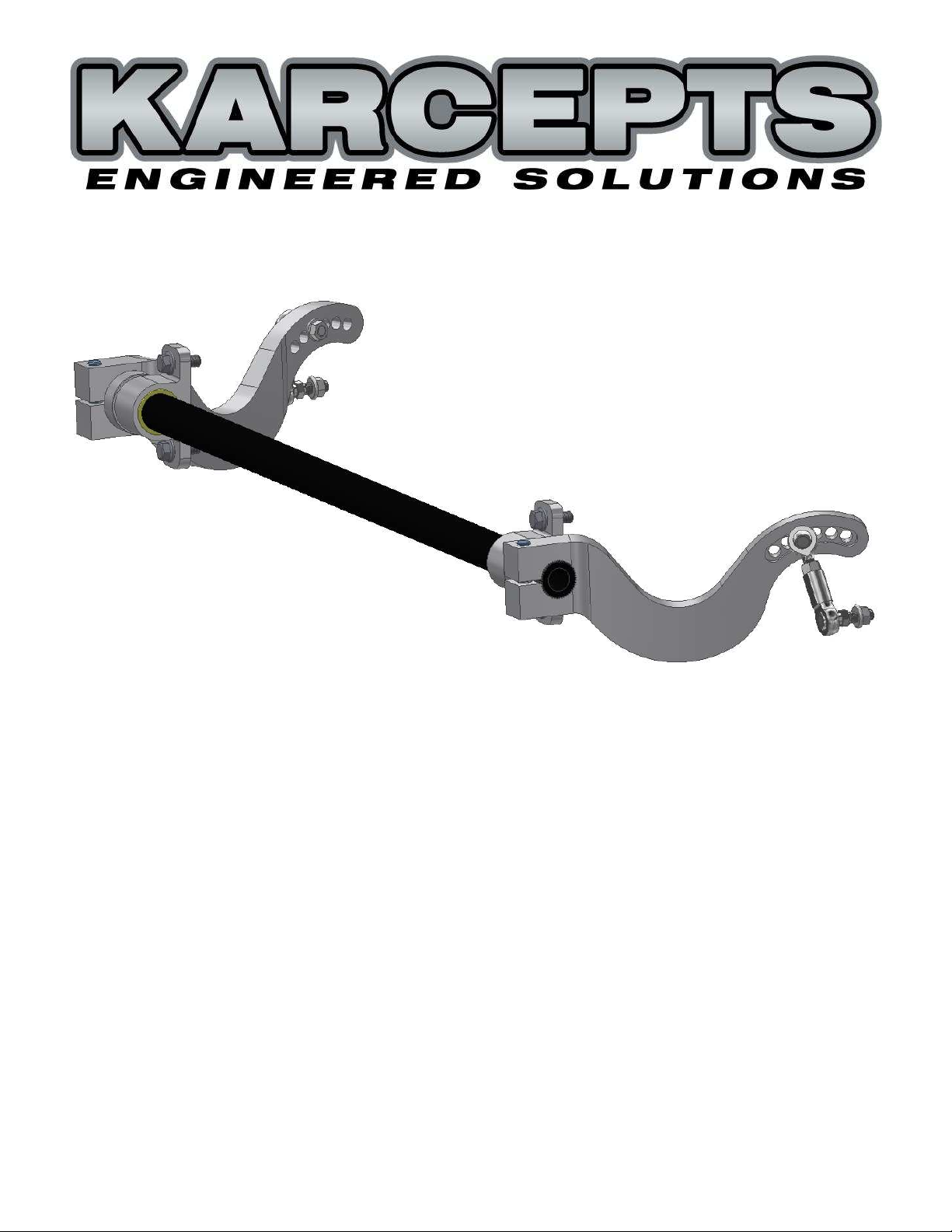
Installation Instructions for Part #: KFSB-AP-XX
Karcepts Front Sway Bar Kit for 2000-2009 Honda S2000
Specifically for track/autocross use, this sway bar kit offers zero compromises:
- Billet aluminum arms optimized for strength and weight utilizing the latest FEA software
- Like a blade style sway bar, roll stiffness can be adjusted quickly, and with one wrench
- Unlike a blade style sway bar, adjustments are finite, with no possibility of slipping position
- 6 adjustment positions per sway bar arm
- Light weight, zero deflection solid sway bar mounts provided for precise feel
- Low friction, lubrication free, dirt resistant, solid polymer bearings require no maintenance
- Heat treated and plated steel alloy PTFE lined endlinks and all hardware included
- 32mm (1.25") diameter high-grade spring steel splined center section for consistent rates
- Center section available in different wall thicknesses (0.120", 0.188", 0.250", and solid)
- Stiffest setting yields 11% more angular twist on a given center section compared to any other
splined style S2000 front sway bar on the market
Karcepts, Inc.
www.karcepts.com
info@karcepts.com

Parts Included With S2000 Front Sway Bar Kit
DESCRIPTION QTY
SOLID SWAY BAR MOUNT 2
M10X25 FLANGE BOLT 4
SPLINED SWAY BAR CENTER SECTION 1
CLAMP COLLAR 2
LEFT SWAY BAR ARM 1
RIGHT SWAY BAR ARM 1
M12X50 SOCKET HEAD CAP SCREW 2
SWAY BAR ENDLINK 2
3/8" NYLON-INSERT LOCKNUT 2
3/8" FLANGE NUT *4
*
Only quantity of 2 needed for assembly. Quantity of 2 extra provided as spares.
HEAVY DUTY CABLE TIES 4
Tools Required
Torque Wrench
Sockets - 17mm, 14mm, 10mm hex bit, 9/16", 3/16" hex bit
1/2" Open End Wrench
9/16" Ratcheting Combination Wrench
Tape Measure
Rubber Mallet
Note
Please read these instructions in full before attempting installation. If you do not
believe you are qualified in performing the necessary installation, please find an
experienced professional who can. Due to the nature of racing components
(external shock reservoirs, piggyback canisters, aftermarket brakes/brake lines,
oversized wheels/tires), it is your responsibility to make certain adequate clearances
between aftermarket chassis components and our sway bar are met. Karcepts,
Inc. will not be held responsible for damaged components due to unresolved
interference issues during installation.
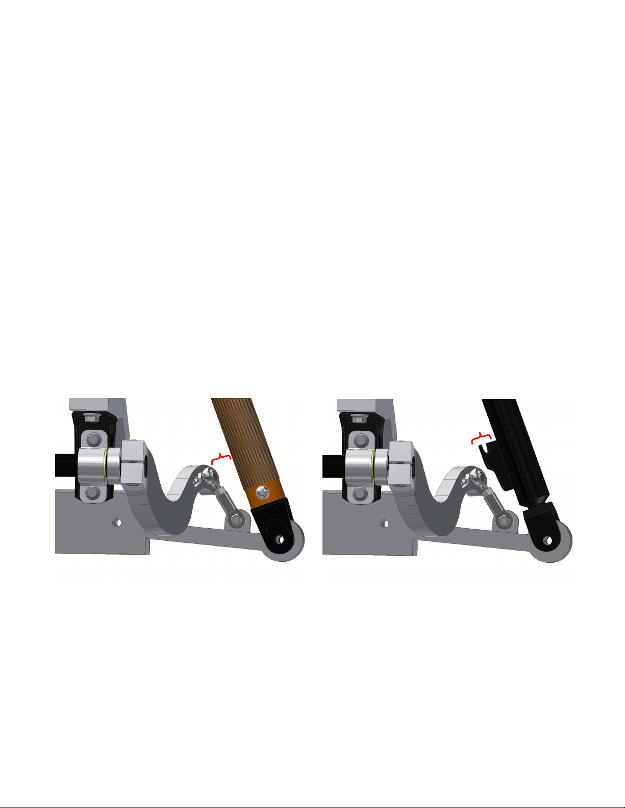
This sway bar kit will only offer quick adjustment options with shock bodies that are
completely cylindrical in shape between the shock body and sway bar arm. Brake
line mounting brackets, remote reservoir lines, nitrogen fill connections, and any
other potential obstructions mounted inboard of the shocks can prohibit quick
adjustment. OEM shocks, Koni Sport shocks, and any other shocks with OEM style
brake line mounting brackets can still function when relocating the left shock to the
right side, and vice versa (or you may grind off the brake like brackets completely).
Since most brake line brackets cannot be utilized if desiring the quick adjustment
feature of this kit, always re-secure brake lines to the shock bodies with heavy duty
cable ties (provided). It's best to tie brake lines as high as possible onto the shock
bodies, as this will keep the lines out of the way when performing an adjustment.
Good (no interference) Bad (bracket needs addressed)
The succeeding installation instructions assume the above precautions have already
been checked or addressed.
Please consult us if you have any concerns with your application.
1. Solid Mount/Center Section Installation
A. Raise the front of the vehicle and support it with jack stands.
B. Remove the front wheels, splash shield, sway bar, sway bar bushing holders,
and endlinks.
C. The factory sway bar mounting brackets (OEM steel brackets that mount under
the frame rails) must be utilized in conjunction with the Karcepts Solid Sway Bar
Mounts. Never use any other aftermarket sway bar mounts with this kit as they
will alter the geometry. If the factory brackets are currently installed on the
vehicle, now is a good time to double check their tightness to the frame. The
factory torque spec on these M12 (17mm socket) bolts is 61 ft-lbs.
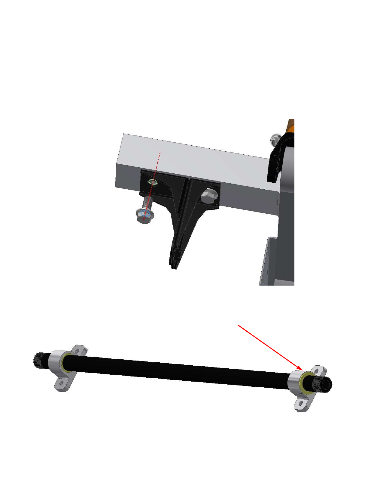
D. Slide a solid mount onto each end of the splined center section. Upon first
install, it can be normal if the mount bushings require some effort to slide onto
the shaft. Note the orientation of the bushing inside each mount. The flanged
side of the bushings must be positioned facing out.
DO NOT oil the bushings with any form of lubricant. The polymer bushings are
infused with solid lubricants and must break-in and run dry.

1. Solid Mount/Center Section Installation (continued...)
E. Install the solid mount/center section assembly onto the factory sway bar
mounting brackets with the provided M10x25 flange bolts and torque to 29 ftlbs with a 14mm socket. Do not be alarmed if observing high friction levels
when trying to rotate the bar at this time. With use, the bushings will break-in
and free up quickly.
F. Slide a clamp collar over each end of the splined center section. Leave the
collar screws loose. There is no need to center the bar perfectly at this time.
You will not be centering the bar based off how much shaft is protruding from
the sides of the mounts as that does not always give a clear indication of true
center (due to subframe position, eccentric alignment bolt positions, as well as
excess hole clearance in the factory sway bar mounting brackets to the frame).

2. Sway Bar Arm Installation
A. Slide the left sway bar arm over the splined end of the center section, leaving
1/16" of shaft protruding past the end of the arm. This is the optimal arm
installation position. Thread the M12x50 socket head cap screw through the
arm; and with a 10mm hex bit socket, torque to 50 ft-lbs.
B. Repeat the above for the right sway bar arm, making certain to clock the right
arm onto the shaft splines to an exact mirror image as the left arm.
Arms clocked properly Arms clocked incorrectly (off one tooth)

3. Quick Adjustment Setup
The quick adjustment feature of this sway bar kit is dependent upon:
1. Arm installation position relative to center section (Section 2 above)
2. Proper endlink length (subject to ride height & arm installation position)
3. Correct sway bar centering
Use the below table to determine ideal endlink length for your ride height:
RIDE HEIGHT *1 ENDLINK LENGTH *2
12.50" 2.63"
12.75" 2.69"
13.00" 2.75"
13.25" 2.81"
13.50" 2.88"
13.75" 2.94"
14.00" 3.00"
14.25" 3.06"
*1
Ride height is measured from the center of the hub to the bottom edge of the fender.
*2
Endlink length is measured from center of ball to center of ball.
A. Endlinks are pre-set to 2.75" by Karcepts, Inc. upon shipment. Re-set endlink
length if your ride height is not 13.00". You may loosen the lock nuts and rotate
one side of the endlink in or out 1.5 rotations to adjust for 1/16" (0.06") of endlink
length. (For example: Your ride height from center of hub to bottom of fender =
13.50". If following the table above, that would mean you need the endlinks to
be 1/8" longer. Simply loosen the lock nuts and unscrew one side of the link 3
full turns, then re-tighten to achieve a 2.88" long endlink.)
Depending on corner balance (differing heights per side of the car w/o driver), you
may realized the left link and right link should differ in lengths per the above table.
At this time, find a happy medium to set both endlinks to the same length. We will
need the endlinks at equal length in order to center the bar at full droop. In future
steps (after centering the bar), you may re-correct endlink length if finding the need
to even do so. We have built in fairly large clearances on this design for ease of
quick adjustment, so endlinks set at equal lengths even with slightly differing left to
right ride heights most likely will not need any correction.
14.50" 3.13"

3. Quick Adjustment Setup (continued...)
B. Install the male half of endlinks into Hole #4 of each sway bar arm and secure
with the 3/8" flange nuts. Proper torque on this nut is 28 ft-lbs, but since this is
the adjustment nut, it's impractical to assume you'll be using a torque wrench
every time you make a sway bar change. Just tighten by feel approximately
close to 28 ft-lbs. Plan to use a 9/16" ratcheting combination wrench on this nut
for quickest adjustments. Install female half of endlinks into the OEM sway bar
endlink locations on the lower control arms. Use a 1/2" open end wrench (to
hold the endlink stud from spinning) along with a 9/16" socket to secure the
provided 3/8" nylon-insert locknuts, and torque to 28 ft-lbs.
Male half of endlink Female half of endlink
3/8" nylon-insert locknut 3/8" flange nut (adjustment nut)

3. Quick Adjustment Setup (continued...)
C. Assuming all bolts and endlinks are tight (but with clamp collars still loose),
center the sway bar assembly by comparing the distance between the endlinks
and the shock bodies. Use a tape measure (or calipers) to assist in the
centering. Again, centering the bar based off how much shaft is protruding
from the sides of the mounts does not give a clear indication of true center (due
to subframe position, eccentric alignment bolt positions, as well as excess hole
clearance in the factory sway bar mounting brackets to the frame). You may
get lucky where that method could work out; but chances are, you must base
the centering off the distance between endlinks and shock bodies as shown
below. If necessary, use a rubber mallet to tap on the sway bar arms to adjust
the position until center is found. Once in position, slide clamp collars tight up
against the bushings of the solid mounts and torque clamp collar screws to 12
ft-lbs (144 in-lbs) with a 3/16" hex bit socket. Make certain there is no
clearance between the solid mounts and the shaft collars once torqued. As a
check, grab a hold of the sway bar center section with both hands, and with all
your strength, try to rock the bar side to side, back and forth (make sure the
vehicle is securely supported before doing so). If you feel any side to side play,
you will need to re-set one of the shaft collars to get rid of the excess
clearance. Functionally, if there is a little side to side play, there will be no ill
effects; however, some side to side play may attribute to a knocking noise.

3. Quick Adjustment Setup (continued...)
D. Lastly, for proper quick adjust functionality, the endlinks must be set to achieve
maximum articulation when installed in the current #4 Hole setting.
To do so, first loosen the endlink lock nut (middle nut of endlink).
Now, rotate both the top and bottom of the endlink halves clockwise until they
bottom out on themselves and will not rotate any further clockwise.
Finally, tighten the endlink lock nut. Once secure, you can rotate the endlink by
hand and should observe a good amount of sweep back and forth on the link,
verifying a large range of articulation has been achieved.

4. Quick Adjustment Procedure
Re-install the splash shield, wheels/tires, and get the car back on the ground. The
car is now ready to test the Quick Adjustment Procedure.
The adjustment procedure of this sway bar kit should take no longer than 3 minutes
to complete with adequate practice and knowledge of the product. For first timers,
you may find yourself spending more time than expected until familiarity is gained.
Additionally, when first learning the procedure, it's best to crank the wheel full lock to
the right when adjusting the left arm position and vice versa (so that you can view
what you are doing). With experience and feel, you will be able to make sway bar
adjustments with the wheels pointed straight ahead (which decreases the amount
of time to adjust).
Before attempting to make a sway bar adjustment quickly at the track or between
autocross runs, we highly recommend spending a good hour practicing and gaining
familiarity with the product/procedure. It's best to follow the below steps exactly as
provided. If trying to take any short-cuts in the below steps, you may cause yourself
excess time or frustration.
1. To start, (turn the wheels full lock to the right and then) loosen and remove the
adjustment nut on the back side of the left sway bar arm with a 9/16" ratcheting
combination wrench. Set the nut aside and remove the male stud of the
endlink from the arm. If there is any difficulty removing the stud due to any
preload, crack loose the adjustment nut on the right side arm, then come back
to the left side and you will be able to remove the stud from the release of
preload. Articulate the endlink around as required, and insert the stud of the
endlink into the newly desired hole position. Pay attention to the wrench flats
on the endlink stud as well as the machined slot of the sway bar arm. The flats
will need to lie within the slot of the sway bar arm. However, at this initial stage,
it can be common for the endlink not to want to install completely within the slot
of a new hole location. If there is any difficulty seating the stud fully within the
arm; do not force anything, just simply leave the stud sitting partially inserted
into the new hole position. If you do manage to seat the stud fully into the new
hole/slot, just leave as is and DO NOT affix the adjustment nut at this time, that
will be completed in Step 3.
2. (Turn the wheels full lock to the left and then) Loosen and remove the
adjustment nut on the back side of the right sway bar arm. Since the left side
endlink has still been left unsecure, it will be extremely easy to remove and reposition this right endlink. If any difficulties, simply push up or down on the
sway bar arm, and all should be free to re-position. Affix the right endlink stud
into the new desired adjustment hole by making certain the wrench flats of the
stud are seated fully into the machined slot of the arm (3/8" of thread will
protrude from the back of the arm). Re-install the adjustment nut and tighten
by feel to approximately 28 ft-lbs.
3. Lastly, go back to the left side of the vehicle (turn the wheels back full lock to
the right) and completely secure the left side endlink stud into the sway bar slot.
Re-install the adjustment nut and tighten by feel to approximately 28 ft-lbs.

5. Quick Adjustment Troubleshooting
If following the Quick Adjustment Procedure, there should be no issues completing
Steps 1 & 2. If there is any difficultly with Step 3 of the procedure, this can mean
one of a few things:
1. The vehicle's suspension has not settled properly back to ride height. Repeat
any above steps necessary within these instructions and get the endlinks
installed back into Hole #4 on each arm. Drive the car around, turn left and
right, do some hard braking, and get the suspension settled and re-try the
Quick Adjustment Procedure.
2. If the vehicle is sitting on extremely un-even pavement, there may be difficulties
due to additional preload. Reposition the vehicle on a different surface and retry the Quick Adjustment Procedure. However, if you are stuck on an un-even
surface, you can correct by performing the following: At the end of Step 2, after
seating the endlink stud fully within the slot of the right side sway bar arm,
thread on the adjustment nut; yet, do not tighten it fully. Let the nut remain a
full turn or two loose. Complete Step 3; and then for a final Step 4, go back to
the right side and finish tightening the adjustment nut.
3. Double check to make certain the sway bar is centered completely, then re-try
the Quick Adjustment Procedure.
4. Double check to make certain the proper endlink lengths are used per the table
in Section 3. If ride height is different between left and right sides of the vehcile,
set left and right endlink lengths accordingly.
5. If all else fails, the endlink length on one side of the vehicle may simply need to
be modified. So if at Step 3 the endlink seems too long or too short to install
into the newly desired hole position, with the car still on the ground, crack loose
on the center endlink lock nut, and then increase or decrease endlink length
until able to insert the endlink stud completely within the slot of the arm.
Tighten the adjustment nut onto the back of the arm. Now, re-set the
maximum endlink articulation by completing 3.D of these installation
instructions (but in this case, you will be completing 3.D with the vehicle still on
the ground). If making an endlink length correction, please test the Quick
Adjustment Procedure multiple times to confirm the new endlink length is ideal.
It should not be necessary to deviate far from the endlink lengths provided on
the table of Section 3.
If there are any issues installing endlinks into Hole #2 due to shock body
interference, this can mean one of two things:
1. Test installing endlinks into Hole #2 on both sides of the vehicle. If only one
side has interference, the sway bar is not centered properly. Re-center the
sway bar correctly and try again.
2. Shock bodies larger than 2.25" in diameter may encounter this interference. To
correct, re-set the arm installation position (Section 2) to a larger value than the
specified 1/16" until clearance is achieved. Endlink length must also be
increased from the Section 3 table values by the same additional increment of
length that was added to the 1/16" arm installation position.

Disclaimer/Warranty:
Due to the nature of high performance applications, Karcepts, Inc. products are
sold without any warranty of merchantability or fitness or purpose, express or
implied. It is expressly understood and agreed between Karcepts, Inc. and
purchasers that as part of the bargain between Karcepts, Inc. and purchasers,
consideration of doing business with each other, all purchasers take, select, and
purchase said products and services from Karcepts, Inc. “as is” and “with all faults”
and Karcepts, Inc. shall provide purchaser with a full and complete opportunity to
examine parts, inventory or services when purchasing from Karcepts, Inc.
Karcepts, Inc. shall not under any circumstances, be liable for any special,
incidental, or consequential damages, including, but not limited to, damages or loss
of other property of equipment, loss of profits or revenue, cost of purchased or
replacement goods, or claims of customers of the purchaser which may arise
and/or result from the sales, installation or use of these parts.
Parts sold or manufactured by Karcepts, Inc. may not meet legal requirements for
use on public roads. It is the user’s responsibility to know and comply with all local
and federal laws and regulations. Use or installation of Karcepts, Inc. products may
affect user insurance and/or vehicle warranty coverage. It is the user’s sole
responsibility for consequences that may occur due to having the product installed
in his/her vehicle.
Karcepts, Inc. assumes no legal responsibilities and/or liabilities, whether to user’s
vehicle, engine, person(s), and/or property(s), that result from the use of, or servicing
of a vehicle of which a Karcepts, Inc. product has been installed/attempted to be
installed, or to any other vehicle(s) and/or person(s), regardless of whether or not
this product has any involvement directly or indirectly and/or liability, and/or whether
or not proper installation has been carried forth.
Acquisition of a Karcepts, Inc. product will act as an acknowledgement of the legal
disclaimer stated herein.
 Loading...