


PROLASER® ELECTROTA
™
Self-leveling Rotary Laser Level
Model No. 8991
User Manual
Up to 300m/980'
165'/50m
with detector
Rechargeable
batteries
included
4 x C type
included

EN
Thank you for purchasing the Prolaser
®
Electrota™ 8991 SelfLeveling Rotary Laser Level. You are now the owner of one of
our innovative, state of the art tools. These tools incorporate
new laser technology, enabling the professional user and the
serious DIY enthusiast to achieve accurate results and reduce
valuable work time.
APPLICATIONS
®
The Prolaser
Electrota™ 8991 has been designed for use in
most areas of construction, for example:
• Laying foundations
• Wall and fence construction
• Laying sloped water and sewage lines
• Laying ooring
• Hanging acoustic ceilings
• Installing partitions and drywall
Up to 300m/980'
165'/50m
with detector
Rechargeable
batteries
included
4 x C type
included
NOTE
Keep this user manual for future reference.
2

CONTENTS
• Features 4
• Safety instructions 5-6
• Overview 7-8
• Operating Instructions 9-16
Horizontal Plane (Automatic Mode) 9
Inclined Plane 10
Manual Mode 11
Vertical Setup 12
Plumb Down 13
Scan Function 13
Manual Rotation 14
Automatic Drift System 14
Laser Detector 15
Using the Laser Detector 15
Using the Remote Control 16
• Power Supply 17-18
• Care and Maintenance 19
• Field Calibration Test 20-21
• Specifications 22
• Warranty 23
3

FEATURES
• Self-leveling electronic mechanism on slopes of ±5°
• 360° rotation generates a horizontal or vertical level plane
• Generates an inclined plane of up to ±5° in both the X and
Y planes
• Five variable speeds (0, 60,120, 300, 600 rpm)
• Scan modes create visible laser lines
• Supplied with rechargeable batteries and battery
Charger-AC/DC Converter
• Plumb Down/Plumb Up point
• Rugged design with protective handles.
• Freestanding or ts onto standard tripod (5/8" thread)
• Remote control included
• Laser Detector included
• Shockproof protective case included
• IP-65 protection from dust and moisture
®
• Laser beam enhancement Beamnder
NOTE
glasses included
This device contains precision components
that are sensitive to external shock, impact or
falls which may compromise its functionality
–handle with care to maintain its accuracy.
4

SAFETY INSTRUCTIONS
WARNING
This product is emitting radiation that is classified
as class II according to EN 60825 -1
The laser radiation can cause serious eye injury
• Do not stare into the laser beam
• Do not position the laser beam so that it unintentionally
blinds you or others.
• Do not operate the laser level near children or let children
operate the laser level.
• Do not look into a laser beam using magnifying optical
devices such as binoculars or a telescope, as this will
increase the level of eye injury.
WARNING: This product contains lead in solder and
certain electrical parts contain chemicals which are
known to the State of California to cause cancer, birth
defects or other reproductive harm.
(California Health & Safety Code Section 25249.6- Proposition 65)
NOTE
The red goggles are intended to enhance the
visibility of the laser beam. They will not
protect your eyes against laser radiation.
5

• Do not remove or deface warning labels on the laser level.
• Do not disassemble the laser level.
• Do not drop the laser.
• Do not use solvents to clean the laser.
• Do not use in temperatures below -20°C or above 50°C
(-4°F / 122°F)
• Do not operate the laser in explosive atmospheres such as
ammable liquids, gases or dust. Sparks from the tool can
cause ignition.
• When not in use remove the batteries, engage the
pendulum lock and place the laser in the carrying case.
• Make sure the pendulum lock mechanism is engaged
before transporting the laser.
NOTE
If the laser level is not in use for a prolonged
period of time, remove the batteries from the
battery compartment to prevent leakage or/
and corrosion damage.
If the pendulum lock mechanism is not
engaged before transportation, internal
mechanical damage may occur.
6

OVERVIEW
Main body
1. Laser Diode.
2. Plumb Up Beam window.
3. Control Panel.
4. Carrying Handle.
5. Charger socket.
7
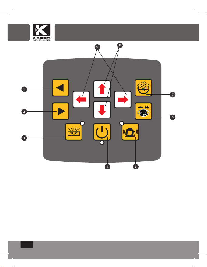
Control Panel
1. Rotation left
2. Rotation right
3. Manual/Auto (in manual mode the self leveling is disabled)
4. Power On/Off
5. Automatic drift system
6. Rotation Speed Control
7. Direction Scanning
8. Y-AXIS
9. X-AXIS
8

OPERATING INSTRUCTIONS
To get the most out of your Prolaser
®
Electrota™ 8991, please
adhere carefully to the following instructions.
Note: Avoid setting up the laser near heavy machinery or sources
of vibration that may adversely affect the leveling of the laser.
Horizontal Plane (Automatic Mode)
Place the Rotary Laser on a dry, at, vibration free surface or or
on a standard 5/8" tripod (not included) or ceiling to oor leveling
pole (not included) or on any wall mount accessory (not included).
1. Set up the Rotary Laser approximately level; the instrument
can compensate for up to ±5° from the horizontal plane.
2. Press the On/Off button. The power indicator will light up
and the laser beam will blink. If the instrument is set up outside
the ±5° limit, the manual indicator will blink and rotation will not begin.
3. Verify that the Rotary Laser is in automatic mode - the manual
indicator must be unlit.
4. The Rotary Laser is ready to work when the laser beam no
longer ashes. The instrument is now level and the laser
head will rotate at 600 rpm.
5. To make the beam more visible, change the rotating speed
(see page 13), change scanning mode (see page 14), or
use the Laser Detector to detect the laser beam (see page 15).
6. You can use the remote control to control the Rotary Laser
(see page 16). This option is very useful for trench work or
when laying concrete.
7. To turn the Rotary Laser off, press the On/Off button.
9

Inclined Plane
The Rotary Laser can be set up to create a single or dual
directional inclined planed at ±5° from the horizontal plane. This
is very helpful for laying inclined concrete surfaces, ensuring runoff pathways as well as laying water and sewage lines.
1. Set up the Rotary Laser approximately level; the instrument
can compensate for up to ±5° from the horizontal plane.
2. Press the On/Off button. The power indicator will light
up and the laser beam will blink. If the instrument is set
up outside the ±5° limit the manual indicator will blink and
rotation will not begin.
3. The Rotary Laser is ready to work when the laser beam no
longer ashes. The instrument is now level and the laser
head will rotate at 600 rpm.
4. Press the Manual/Automatic button to change the rotating
laser to Manual Mode.
5. Verify that the Manual
indicator is lit.
6. For X direction slope:
Position X axis parallel
to plane requiring slope
setup. Press to raise
X1 and lower X2. Press to raise X2 and lower X1.
For Y direction slope:
Position Y axis parallel to plane requiring slope setup.
Press to raise Y2 and lower Y1. Press to raise Y1 and
lower Y2.
10

7. To make the beam more visible, change the rotating speed (see
page 13), change scanning mode (see page 14), or use the
Laser Detector to detect the laser beam (see page 15).
8. You can use the remote control to control the Rotary Laser (see
page 16). This option is very useful for trench work or when
laying concrete.
9. To turn the Rotary Laser off, press the On/Off button.
Manual Mode
If the Manual/Auto button is pressed and the LED indicator, next
to it, is lit then the self-leveling is disabled and the laser beam will
rotate regardless of the position of the level. The level can be set as
required and used to mark the line at any angle.
11

Vertical Setup
The Rotary Laser can be set up to create a vertical laser
line, to check the vertical alignment of a wall or fence pole.
1. Position the Rotary Laser on its side
on a dry, at, vibration free surface or
on a standard 5/8" tripod (not included)
or ceiling to floor leveling pole (not
included) or on any wall mount accessory
(not included). Set up the Rotary Laser
approximately level; the instrument can
compensate for a variance of up to ±5°
from the vertical plane.
2. Press the On/Off power button to turn the Rotary Laser
on. The power indicator will light up and the laser beam
will start to blink.
3. Verify that the Rotary Laser is in Automatic mode - the
manual indicator must be unlit.
4.The Rotary Laser is ready to work when the laser beam
has stopped ashing. The instrument is now level and the
laser head will rotate at 600 rpm.
5.If the laser beam is not sufciently visible, adjust the
rotation speed (see page 13), or use the Laser Detector to
detect the laser beam (see page 15).
6.You can use the remote control to control the Rotary
Laser (see page 16). This option is very useful when
working at heights or on scaffolding.
7.To turn the Rotary Laser off, press the On/Off button.
12

Plumb Down
The Plumb Down feature enables you to center the Rotary
Laser onto a selected point. It is much easier to use this
feature if you set up the Rotary Laser on a tripod with a
hollow connecting bolt.
1. Set up the Rotary Laser on a tripod.
2. Move the tripod and Rotary Laser so that they are
approximately above the selected point.
3. Level the Rotary Laser as in Horizontal Setup.
4. Turn the Rotary Laser On.
5. Move the Plumb Down beam onto the selected point on
the ground by raising and lowering the tripod legs.
6. Level the Rotary Laser again and adjust the Plumb Down
beam with the tripod legs as in step 5.
7. Repeat step 6 until the Plumb Down beam is sufciently
accurate for your purposes.
8. If you wish to transfer a point to the ceiling, use the Plumb
Up beam once the Rotary Laser is accurately centered.
Changing Rotation Speed
The laser beam is more visible when the rotation speed is slower.
Change the speed of the rotating laser head by pressing the
Speed control button. The default option is 600 rpm. Pressing
on the Speed control button moves the speed cycle a step
forward (600 0 60 120 300 600 rpm)
To transfer a level mark over long distances or in poor
visibility, the rotation can be stopped (speed = 0 rpm). The
laser beam can then be accurately positioned using the
Rotation Left and Rotation Right buttons.
13

Scan Function
The Scan function is used to limit the area covered by the laser
beam, for safety reasons or to improve visibility and sensitivity.
A smaller scan segment will be more visible than a larger one.
The default mode is a 360° rotation, which provides a
horizontal or inclined beam throughout the work area or room.
The scan button changes the mode from a 360° rotation to a
10° 45° 90° 180° 360° rotation. Press the scan button
until the laser is set at the desired scan mode. The scan mark
can then be accurately positioned using the clockwise and
counterclockwise rotation controls.
Manual rotation
When the laser beam is at 0° rpm or in scan mode you can
manually rotate the beam using Rotation left and Rotation right
keys.
Automatic drift system
Use this function to prevent misaligning the laser level while in
automatic mode.
Press the Automatic drift system key after turning the laser
level on automatic mode. The LED indicator, near the key, will
ash, engaging the automatic drift system. The laser level will
not re-level itself or spin again after any displacement while
on automatic mode. If the laser level does not rotate while the
LED indicator near the Automatic drift system key ashes more
frequently, then the level was shifted during its operation.
Check the position of the laser beam and readjust it, if needed,
before turning it on again. Disengage the automatic drift
system, check / readjust the position of the device and turn it
on again.
14

Laser Detector
The Prolaser
®
Electrota™ 8991 is effective up to 300m (980ft)
when used together with the Laser Detector.
Use the Laser Detector when it is hard to see the light beam,
such as outdoors or in bright rooms.
Attach the Laser Detector to a rod if the laser unit is positioned
above head height.
Using the Laser Detector
1. Press the On/Off button.
2. Press to select the ne or coarse detection mode (a symbol
appears on the right of the LCD, displaying which mode was
selected).
3. Select the sound or mute mode. The sound symbol
appears on the display when you select the sound option.
No symbol, indicates that you are in mute mode.
4. Turn the detection window towards the laser beam and
move the detector up and down following the direction of
the arrow on the LCD.
• Lower the Laser Detector if the arrow points down
(beeping sound).
• Raise the Laser Detector if the
arrow points up (beeping sound).
5. The level marks on the sides
of the Laser Detector are level
with the laser beam when the
horizontal beam is displayed
on the LCD (continuous sound).
1. Sound/mute mode
2. On/Off button
3. Fine/coarse adjustment button
15

Using the Remote Control
The laser can be operated by an infra-red remote control.
The remote control will only work if there is an uninterrupted line
of sight between the infra-red control and the remote control
sensor, on the control panel.
The effective range of the remote control is 20m.
The Remote Signal Indicator ashes when a signal has been
sent.
1. Remote Signal Indicator
2. Rotation speed control button
3. Scanning mode control button
4. Rotation right button
5. Rotation left button
6. Manual/Automatic mode button
7, 8. X-AXIS
9, 10. Y-AXIS
16

POWER SUPPLY
Rotary Laser
The Prolaser
®
Electrota™ 8991 is supplied with on-board internal
rechargeable batteries and a battery charger (AC/DC Converter).
Note: A bracket and a set of four regular type C batteries are
also supplied for optional use.
1. Recharge the batteries when the
power indicator on the
control panel starts to ash.
2. Plug the battery charger into a
power source.
3. Insert the plug of the battery
charger into the socket on the laser
level or on the battery pack.
1. Battery charger
2. Bottom of laser
3. Rechargeable batteries
Note: You can charge the rechargeable battery pack inside or
outside of the laser level. The Rotary Laser can be operated
while recharging. It takes approximately seven hours to fully
charge the batteries. Brand new or unused rechargeable
batteries require three recharge / discharge cycles to attain full
capacity.
4. The indicator LED on the battery charger lights steady red
while charging and steady green when fully charged. The
indicator LED will ash if not connected to the batteries.
5. The battery pack can be removed from the Rotary Laser by
unscrewing the locking nut, holding the battery pack in place.
Note: If the laser level is not in use for a long period of time,
remove the battery pack from the battery compartment. This will
prevent leakage or/and corrosion damage.
17

Laser Detector
1. Press the battery compartment lock and open the battery
compartment cover.
2. Remove the 9V alkaline battery.
3. Replace with a new 9V alkaline battery.
4. Re-close the cover.
Remote Control
1. Slide off the battery compartment cover.
2. Remove the spent batteries.
3. Replace them with two "AAA" batteries.
4. Replace the cover.
External Power Supply
®
The Prolaser
Electrota™ 8991 can use an external DC power
source. This will minimize the risk of battery failure during
operation.
Use only the combined Battery Charger-AC/DC Converter
supplied with the Rotary Laser, otherwise irreparable damage
will be caused to the instrument and your warranty will be invalid.
The suitable power range of the combined Battery Charger-AC/
DC Converter is 50 - 60Hz, 100VAC-240VAC.
18

CARE AND MAINTENANCE
Preventative Maintenance
• Store in a clean dry place.
• If the Rotary Laser is wet, dry off with a dry cloth.
• Do not seal the laser in the carrying case until completely dry.
• Do not attempt to dry the Rotary Laser by re or with an electric dryer.
• Do not drop the Rotary Laser, avoid rough treatment, and avoid
constant vibration.
• Periodically check the calibration of the Rotary Laser.
• Clean with a soft cloth, slightly dampened with a soap and water
solution. Do not use harsh chemicals, cleaning solvents or strong
detergents.
• Keep the laser aperture of the Rotary Laser clean by wiping it
with a lint-free cloth moistened with isopropyl (rubbing) alcohol.
• Keep the Detection window of the Laser Detector clean by wiping
it with a soft cloth moistened with glass cleaner.
Repairs
• See the Warranty section at the end of this manual.
®
• Do not take the Prolaser
any unqualied person to take the laser level apart. Unauthorized
servicing may cause bodily injury, irreparably damage the Rotary
Laser and invalidate the warranty.
Electrota™ 8991 apart or permit
19

FIELD CALIBRATION TEST
The Rotary Laser leaves the factory fully calibrated. Kapro
recommends that the level be checked regularly and especially
after the unit has been dropped or mishandled.
Horizontal Plane Calibration Test
1. Set up the Rotary Laser approximately 50m (165ft) from a wall
or measuring staff.
2. Position the Rotary Laser so that the X-axis is pointing in the
direction of the measuring staff or wall.
3. Turn on the Rotary Laser.
4. Mark the height of the laser beam on the wall or measuring
staff (h1).
5. Rotate the Rotary Laser 180°.
6. Mark the height of the laser beam on the wall or measuring
staff (h2). The difference between the heights should not
exceed 10mm (3/8 inch).
7. Repeat the procedure for the Y-axis.
20

Horizontal Line Calibration Test
1.Set up the Rotary Laser on a level surface, between two walls
or measuring staffs that are about 100ft (30m) apart.
2. Position the laser about 0.5m (1.5ft) from 1st wall/staff.
3. Position the laser on vertical leveling side.
4. Turn on the Rotary Laser, with the Plumb up/Plumb down
projecting onto walls. Check and mark points (hA and hB) on
both walls.
5. Reposition the laser 0.5m (1.5ft) from 2nd wall/staff, pointing in
opposite direction. Check and mark points (hA' and hB') on
both walls.
6. Δ1=hA-hA'
Δ2=hB-hB'
7. The difference between Δ1 and Δ2 should be less than 6mm
(1/4 inch).
21

SPECIFICATIONS
Horizontal/Vertical Beam
Accuracy
Self Leveling Range ±5°
Waterproof / Dustproof Standard IP 65 (International
Recommended Working
Range
Laser Source 635 ± 5nm laser diode
Classication Laser Class II
Rotational Speed (rpm) 0 (stationary point), 60,120, 300, 600 rpm
Rotational Coverage
(scanning function)
Setting slope ±5° (dual axis)
Effective Working
Temperature
Remote Control Distance Approx. 20m
Remote Control Power Supply 2 x "AAA" batteries
Laser Power Supply DC 4.8-6V Ni-MH Rechargeable
Laser Battery Life Approx. 20 hours of continuous use
Laser Detector Power Supply One 9V alkaline battery
Laser Detector Battery Life 50 hours of continuous use
Weight 2.45 kg ±0.1kg with batteries
Dimensions (LxWxH) 206(L) X 206(W) X 211(H)mm
± 0.1mm/m (0.0001"/")
Electrotechnical Commission)
Indoor 50m (160 ft)
Outdoor 300m (980 ft) with Laser Detector
Plumb down point 650 ±5nm laser diode
0° (stationary point), 10°,45°, 90°,180°, 360°
-4°F —122°F (-20°C — 50°C)
or 4 C type alkaline
22

WARRANTY
This product is covered by a two-year limited warranty
against defects in materials and workmanship. The warranty
does not cover products that are used improperly, altered
or repaired without Kapro Tool's approval. In the event of a
problem with the laser level, please return the product to the
place of purchase with proof of purchase.
Model #8991
The serial number sticker is positioned inside the battery
compartment.
23

Rev. 1.0 © 2019 Kapro Industries Ltd.
24
 Loading...