

Page 1

MT1200 and MT1200G
Users Guide: Introduction,
Getting Started,
Modes of Operation,
Command Reference, and
Hardware Specifications
Kantronics
3115 W. 6th St., Suite A
Lawrence, Kansas 66049
Orders / Inquiries (785) 842-7745
FAX (785) 842-2031
e-mail: sales@kantronics.com
website: www.kantronics.com
Service / Technical Support (785) 842-4476 (8 AM to 12 noon and 1 PM to 5 PM Central Time, M-F)
FAX (785) 842-2031
e-mail: service@kantronics.com
Page 2

Page 3

REVISIONS
Revision Date Description
REV- 2006-12-29 Release version
REV-B 2007-03-06 Corrections, updates, additions
i
Page 4

The MT1200 is a Kantronics hardware and software design incorporating the AX.25 Level 2 Version 2 Packet
protocol as adopted by the American Radio Relay League. It is designed to be used as a GPS beacon from a
mobile environment.
We have attempted to make this manual technically and typographically correct as of the date of the current
printing. Production changes to the TNC may add errata or addendum sheets. We solicit your comments
and/or suggested corrections.
Please send your comments and/or suggestions to:
Kantronics Co., Inc.
3115 W 6
th
St., Suite A
Lawrence, KS 66049.
The MT1200 is manufactured in the U.S.A.
© Copyright 2006 by Kantronics Co., Inc. All Rights Reserved.
Contents of this publication or the firmware within the MT1200 may not be reproduced in any form without the
written permission of the copyright owner.
MT1200 is a registered trademark of Kantronics Co., Inc.
KPC-3 Plus is a registered trademark of Kantronics Co., Inc.
KPC-9612 Plus is a registered trademark of Kantronics Co., Inc.
KAM ’98 and KAM XL are registered trademarks of Kantronics Co., Inc.
APRS is a registered trademark of Bob Bruninga, WB4APR.
HyperTerminal is a registered trademark of Microsoft.
ii
Page 5

Kantronics Warranty Registration
Please take the time to fill out the warranty registration form (or a copy of the form) and mail it to Kantronics,
including a copy of your sales receipt, to register your purchase. Kantronics must receive warranty registration
within 60 days of purchase of the Kantronics MT1200 to be valid. Both must be on file at Kantronics in order
for you to receive warranty service. Refer to the warranty policy in this manual for further information.
Warranty Registration form and copy of sales receipt may be e-mailed to sales@kantronics.com.
Mail form and sales receipt to:
KANTRONICS
3115 W. 6th St., SUITE A
LAWRENCE, KS 66049
Warranty Registration
Last Name: __________________________
First Name: __________________________ Call Sign: ___________________________
Mailing Address: _________________________________________________________________________
City: _______________________________ Telephone: ____________________________________
State: ______________________ E-Mail: _______________________________________
Zip/Postal Code: ______________________
Country: ____________________________
Product: MT1200(G)
Date of Purchase: _____________________ Dealer: _________________________________________
Note: The serial number of the unit is displayed to the terminal in the sign-on message when the MT1200 is
powered on.
Serial #: ________________________________________
iii
Page 6

IMPORTANT:
READ THIS PAGE BEFORE YOU INSTALL YOUR NEW KANTRONICS PRODUCT
This product contains SOFTWARE in FLASH memory and/or diskette and/or CD, which
is protected by both United States copyright law and international treaty provisions.
If you install or use this product, you will be deemed to be bound by the terms of the
SOFTWARE license shown below. If you do not wish to be bound by such license,
return such product and all associated documentation unused to your supplier for
refund of the amount you paid.
License Agreement
1. License. In consideration of payment of the License Fee, which is included in the
price of the product, the Licensee (you) is granted by the Licensor (Kantronics
Company, Inc. - Kantronics) a non-exclusive right to use the SOFTWARE and
associated documentation. No ownership rights to the SOFTWARE or its
Documentation are transferred from Kantronics to you.
2. Term. This License Agreement is effective until terminated. You may terminate this
Agreement by destroying the PROM or diskette or CD and Documentation. You may
not rent or lease the SOFTWARE, but you may transfer the SOFTWARE and
accompanying written materials on a permanent basis provided you retain no copies
and the recipient agrees to the terms of this Agreement. Kantronics may terminate
this Agreement without notice if you violate any terms or conditions of the
Agreement. In the event of termination of the Agreement, provisions relating to
Kantronics’ disclaimers of warranties, limitation of liability, remedies, or damages
and Kantronics’ proprietary rights shall survive.
3. Object Code. The SOFTWARE is delivered in object code only. You shall not
reverse compile or otherwise reverse engineer the SOFTWARE.
4. Limited Warranty. This product is covered by the standard Kantronics Co., Inc.
Limited Warranty, which is enclosed.
5. General. This License Agreement constitutes the complete Agreement between you
and Kantronics.
The SOFTWARE and/or Documentation may not be exported or re-exported in violation
of any export laws or regulations of the United States of America or any other applicable
jurisdiction.
iv
Page 7

This Agreement shall be governed by and interpreted under the laws of the State of
Kansas, United States of America.
Use, duplication, or disclosure by the Government of the United States is subject to
restrictions as set forth in subparagraph (c)(1)(ii) of the Rights in Technical Data and
Computer SOFTWARE clause of DFARS 252.227-7013.
Kantronics may in its sole discretion, provide you with upgrades of the SOFTWARE
and/or Documentation if you have provided Kantronics your completed Warranty
registration with a copy of your receipt showing the amount you paid.
LICENSEE ACKNOWLEDGES HAVING READ AND UNDERSTOOD THIS
AGREEMENT AND AGREES TO BE BOUND BY ITS TERMS. LICENSEE FURTHER
AGREES THAT THIS AGREEMENT IS THE COMPLETE AND EXCLUSIVE
STATEMENT OF THE AGREEMENT BETWEEN LICENSEE AND LICENSOR AND
SUPERSEDES ANY PROPOSAL OR PRIOR AGREEMENT, ORAL OR WRITTEN,
AND ANY OTHER COMMUNICATIONS RELATING TO THE SUBJECT MATTER OF
THIS AGREEMENT.
Any questions concerning this Agreement or any other matter relating to Kantronics
Company, Inc. products or business practices may be directed to:
Customer Service Department
Kantronics Company, Inc.
3115 W. 6th St., Suite A
Lawrence, KS 66049
v
Page 8

Page 9

TABLE OF CONTENTS
MT1200 and MT1200G...............................................................................................................................................................................1
REVISIONS.................................................................................................................................................................................................i
Kantronics Warranty Registration..............................................................................................................................................................iii
IMPORTANT:............................................................................................................................................................................................iv
License Agreement.....................................................................................................................................................................................iv
TABLE OF CONTENTS.............................................................................................................................................................................1
LIMITED WARRANTY.............................................................................................................................................................................4
Return/Repair Procedures........................................................................................................................................................................7
International Returns............................................................................................................................................................................9
Radio Frequency Interference Statement...................................................................................................................................................11
RFI Suppression.....................................................................................................................................................................................12
Welcome................................................................................................................................................................................................15
Package Contents...................................................................................................................................................................................15
Additional Parts for Your Packet Radio Station....................................................................................................................................16
Overview of This “User’s Guide” Manual............................................................................................................................................16
Uses of Your MT1200...........................................................................................................................................................................18
Our Assumptions about You..................................................................................................................................................................18
Installing Your MT1200(G).......................................................................................................................................................................19
The MT1200......................................................................................................................................................................................19
Connect Your MT1200 to a Power Source............................................................................................................................................20
Connect your MT1200 to Your Computer.............................................................................................................................................20
Installing the RS232 Cable................................................................................................................................................................23
Cabling an external GPS receiver to an MT1200 .............................................................................................................................24
Alternate GPS Input...........................................................................................................................................................................25
Configure Your MT1200.......................................................................................................................................................................26
HyperTerminal...................................................................................................................................................................................26
AUTOBAUD.....................................................................................................................................................................................27
Setting Basic Communication Parameters.........................................................................................................................................28
Documentation Conventions..................................................................................................................................................................28
Trouble-Shooting Difficulties in Communicating.............................................................................................................................29
Connect the MT1200 to Your Transceiver............................................................................................................................................31
Parts needed for assembling a TNC to Radio cable...........................................................................................................................31
Preparing the Transceiver Cable Assembly.......................................................................................................................................31
Connecting Your Transceiver Cable Assembly.................................................................................................................................39
Adjusting the Receive Volume of Your Transceiver.........................................................................................................................40
Transmit level adjustment..................................................................................................................................................................40
Getting Started...........................................................................................................................................................................................42
The Front Panel of the MT1200.............................................................................................................................................................43
Beginning a Session...............................................................................................................................................................................44
Giving Commands and Transmitting Data............................................................................................................................................44
Check Your MT1200’ Version Number and ID................................................................................................................................45
Get Help.............................................................................................................................................................................................45
View Current Values of Parameters..................................................................................................................................................46
Change the Value of a Parameter.......................................................................................................................................................46
Monitor Communications From Nearby Stations..................................................................................................................................47
Communicate Directly with a Nearby Station.......................................................................................................................................47
Modes of Operation...................................................................................................................................................................................49
Packet Mode...........................................................................................................................................................................................49
Protocol for Amateur Packet Radio: AX.25......................................................................................................................................49
1
Page 10

Command Mode.................................................................................................................................................................................49
Connected vs. Unproto.......................................................................................................................................................................49
Monitoring and Calling CQ...............................................................................................................................................................50
Flow Control......................................................................................................................................................................................50
Convers Mode vs. Transparent Mode................................................................................................................................................52
Exiting Transparent Mode.................................................................................................................................................................52
Linesub mode.........................................................................................................................................................................................54
LINESUB Protocol Description .......................................................................................................................................................54
TUP mode (Transparent Unproto Packet) ...........................................................................................................................................55
TUP Mode Description .....................................................................................................................................................................55
Poll Mode ..............................................................................................................................................................................................57
Poll Mode Protocol Description ........................................................................................................................................................57
Modem Mode.........................................................................................................................................................................................60
KISS Mode.........................................................................................................................................................................................61
XKISS (Extended KISS) Mode.........................................................................................................................................................62
Remote Access ......................................................................................................................................................................................63
GPS Beacon...........................................................................................................................................................................................65
Configuring the MT1200 GPS Beacon..............................................................................................................................................65
Other GPS Beacon Features...............................................................................................................................................................66
GPS Command Summary..................................................................................................................................................................68
Bibliography......................................................................................................................................................................................68
Other Modes of Operation.....................................................................................................................................................................70
Remote Sensing and Control.............................................................................................................................................................70
Command Reference..................................................................................................................................................................................72
Introduction............................................................................................................................................................................................72
Format Defining Commands..............................................................................................................................................................72
Parameter Types.................................................................................................................................................................................73
Entering Commands...........................................................................................................................................................................75
MT1200 Commands..............................................................................................................................................................................77
Appendix A: Advanced Installation.........................................................................................................................................................124
Precautions...........................................................................................................................................................................................124
Cable Wiring........................................................................................................................................................................................124
Diagram of Pin Numbers on DSUB-9 Connector............................................................................................................................124
Connecting to the Computer (Front panel DSUB-9)...........................................................................................................................124
Cable Wiring....................................................................................................................................................................................125
Software settings..............................................................................................................................................................................126
Connecting to your Radios...................................................................................................................................................................126
Radio port pin numbers and functions.............................................................................................................................................126
Interfacing Hand-Held Radios.........................................................................................................................................................127
Optional Connections to DSUB-9 Radio Port.................................................................................................................................129
Connections to the I/O jack..............................................................................................................................................................129
Appendix B: Advanced Information....................................................................................................................................................130
Assembly and Disassembly.............................................................................................................................................................130
Hard Reset/Self-Test............................................................................................................................................................................130
Bios Load.............................................................................................................................................................................................132
Calibration/Equalization......................................................................................................................................................................132
Drive level........................................................................................................................................................................................133
Equalization.....................................................................................................................................................................................133
Microprocessor Watchdog Timer........................................................................................................................................................133
A/D Sensor Inputs................................................................................................................................................................................134
MT1200 Jumpers.................................................................................................................................................................................135
Jumper Locations.............................................................................................................................................................................135
Jumper Descriptions.........................................................................................................................................................................136
Appendix C: In Case of Difficulty...........................................................................................................................................................137
MT1200 Does Not “Sign-On” to Computer........................................................................................................................................137
You Are Unable to Make a “Connect”................................................................................................................................................137
2
Page 11

Cannot Transmit...................................................................................................................................................................................138
Cannot Return to Command Mode......................................................................................................................................................138
Appendix D: Additional Information.......................................................................................................................................................139
Specifications.......................................................................................................................................................................................139
Messages from the MT1200................................................................................................................................................................141
ASCII Chart.........................................................................................................................................................................................146
.............................................................................................................................................................................................................146
MT1200 Parts List...............................................................................................................................................................................147
MT1200 Parts Layout..........................................................................................................................................................................148
3
Page 12

LIMITED WARRANTY
To receive notice of future updates, new product information and prompt warranty
service, please fill in the Kantronics Warranty Registration form COMPLETELY and
return it along with a copy of proof of purchase (to establish purchase date) to
Kantronics Co., Inc., 3115 W. 6th St, Suite A, Lawrence, Kansas 66049 USA. The
Warranty Registration form and proof of purchase may be e-mailed to
sales@kantronics.com.
NOTE: Return of the Warranty Registration form and proof of purchase is a precondition to warranty coverage.
1. WARRANTY. Kantronics Co., Inc. (“Kantronics”) warrants to the first consumer
purchaser (“you”), for the Applicable Warranty Period (as described below), that the
Applicable Product (as described below) will be free from defects in material and
workmanship.
KANTRONICS CO., INC.
LIMITED WARRANTY
Effective January 1, 1997
2. REMEDY. Kantronics agrees that, for any Applicable Product found by Kantronics to
be in violation of the warranty of Section 1 hereof within the Applicable Warranty
Period, it will, at its option, repair or replace the defective Applicable Product at no
charge to you, excluding in-bound shipping charges.
3. EXCLUSIVE REMEDY. Repair or replacement of the Applicable Product, as
provided herein, is the sole remedy available to you against Kantronics, and in no
event will Kantronics be responsible for any other liability or damages or for
incidental, special, or consequential damages, regardless of whether purported
liability is predicated upon negligence, strict tort, contract, or other products liability
theory and whether or not Kantronics is warned about the possibility of such liability
or damages. SOME STATES DO NOT ALLOW THE EXCLUSION OR LIMITATION
OF INCIDENTAL OR CONSEQUENTIAL DAMAGES, SO THE ABOVE
LIMITATION OR EXCLUSION MAY NOT APPLY TO YOU.
4. DISCLAIMER. This Limited Warranty is in lieu of all other warranties expressed or
implied and no representative or person is authorized to assume for Kantronics any
other liability in connection with the sale of its products. KANTRONICS
SPECIFICALLY DISCLAIMS THE IMPLIED WARRANTY OF MERCHANTABILITY
AND IMPLIED WARRANTY OF FITNESS FOR A PARTICULAR PURPOSE FOR
ANY APPLICABLE PRODUCT. IF, HOWEVER, YOU ARE A CONSUMER WITHIN
THE MEANING OF 15 U.S.C. 2301(3), THE ABOVE DISCLAIMER OF IMPLIED
WARRANTIES IS EFFECTIVE ONLY FOR PERIODS OUTSIDE THE APPLICABLE
WARRANTY PERIOD. SOME STATES DO NOT ALLOW LIMITATIONS ON HOW
4
Page 13

LONG AN IMPLIED WARRANTY LASTS, SO THE ABOVE LIMITATION MAY
NOT APPLY TO YOU.
5. APPLICABLE PRODUCTS AND PERIODS. Kantronics products are of two types (1) hardware units and (2) firmware and software for operation of these units,
whether incorporated into the units themselves or separate from the units as
adjuncts or accessories to the units. Hardware units and the media containing
firmware, software and documentation are sold to the consumer purchaser and
become property of the purchaser. Firmware and software are licensed for use by
the consumer purchaser in return for a fee included in the purchase price of the units
and do not become the property of the consumer. (See separate License Agreement
provided with these products). The products to which the warranty of Section 1
hereof applies (herein “Applicable Products”) and the periods during which the
warranty shall apply to such products (herein, “Applicable Warranty Period”) are as
follows:
Applicable Products:
UNITS:
MT1200, KPC-3 Plus, KPC-9612 Plus, KAM XL
Applicable Warranty Period: One (1) year from date of purchase.
MEDIA:
EPROMS or PROMS, CDs, manuals (however bound), specification and
other supplemental pages or any other media on which firmware, software or
documentation are supplied
Applicable Warranty Period: Thirty (30) days from date of purchase.
6. EXCLUSIONS. This Limited Warranty does not apply to the cosmetic appearance
of the Applicable Product; to broken or cracked cabinets; to any accessory not
supplied by Kantronics which is used with the Applicable Product; to any product
that has been subject to misuse abuse or overvoltage; to any product that has been
modified by non-Kantronics personnel unless specifically authorized in writing by
Kantronics; or to any product damaged or impaired by shipping (whether or not
caused by poor packaging), neglect, accident, wiring not installed by Kantronics,
improper parameter settings which are cleared by performing a hard reset, or use in
violation of instructions furnished by Kantronics or of generally accepted industry
practice. Kantronics does not warrant that the functions contained in any software
will meet your requirements or achieve your intended results; or that operation of
any software will be uninterrupted or error-free or without effect upon other software
used with it. Responsibility for the selection of the hardware and software program
to achieve your intended results rests with you.
5
Page 14

7. REMEDY PROCEDURE. Should you need to make a warranty claim, first contact
the dealer from whom you purchased the product. If the dealer is unable to assist
you, contact Kantronics Co., Inc., by mail at 3115 W 6th Street, Suite A, Lawrence,
Kansas 66049 USA; by fax at 785-842-2031; or by phone at our Service / Technical
Support number 785-842-4476 (Hours: 8:00 a.m. to 12 noon and 1 p.m. to 5:00 p.m.
Central Time, M-F). Contact us prior to returning an Applicable Product to receive a
Return Authorization Number. (As a practical matter, problems can often be solved
in such a manner without the product having to be returned to Kantronics for repair
or replacement.)
Return of any Applicable Product for the enforcement of rights under this Limited
Warranty shall be at your expense. Any product returned for warranty service, which
Kantronics determines to be without defect or not covered by this Limited Warranty
shall be subject to the minimum charge for labor and the product will be returned to
you at your sole expense. Please note, no warranty service will be provided until
Kantronics has been furnished with your Warranty Registration card and copy of
proof of purchase establishing purchase date.
8. NON-ASSIGNMENT. This Limited Warranty is not assignable by you. Any attempt
to assign or transfer any of the rights, duties, or obligations hereof is void.
9. OTHER RIGHTS. This Limited Warranty gives you specific legal rights and
you may also have other rights, which vary from jurisdiction to jurisdiction.
6
Page 15

Return/Repair Procedures
Important: Our repair statistics show that over 70 percent of the units returned for
service do not, in fact, require any service. Therefore, we advise you to please doublecheck the following list of common, user-solvable, sources of difficulty before contacting
Kantronics about returning your unit for service.
Check-List for Possible Problems
Should you encounter difficulty in getting your equipment to “talk” to your computer,
please perform at least the following limited checks before calling or writing:
Carefully check your wiring connections to the RS232 port.
If you purchased third-party cables, double-check to be sure that they conform to the
Kantronics’ wiring instructions in this manual.
Verify your terminal baud.
It may be useful to perform a “Hard Reset”. (See Hard Reset section.) If service or
repairs still appear necessary after you have checked the items listed above, it may be
wise to call, fax, e-mail or write Kantronics to determine if the problem can be solved
without returning the unit.
Return Procedures
When calling, report the product name and ask for the Amateur Radio Service
Department. Please have the following information available:
The unit name and serial number (the serial number is found on the bottom of the unit).
The firmware version number (the version number is displayed when you give the
Version command).
If possible, you should have the unit and your computer available to perform
troubleshooting operations when you call.
The Service Department telephone hours are 8:00 AM to 12 noon and 1 PM to 5:00 PM
Central Time, Monday through Friday. If you call outside these hours, the phone will just
ring. The service department telephone is not connected to the main switchboard and
the switchboard receptionist cannot transfer you to the service number. If lines are busy,
you may wish to (and it may be faster to) contact service by letter, fax, or e-mail.
Service e-mail is currently checked twice per day. Before contacting us, please take the
time to list out your problem fully and carefully.
7
Page 16

Here is our contact information:
Kantronics Co., Inc.
3115 W. 6th St, Suite A
Lawrence, KS 66049
service phone line: 785-842-4476
service fax line: 785-842-2031
service e-mail address: service@kantronics.com
website address:
www.kantronics.com
When writing, faxing, or e-mailing Kantronics, include a clear description of the problem,
unit name, firmware version, computer type, computer software used and if possible a
list of current parameter values for your unit (as shown in a DISPLAY listing). Be sure to
include a return fax number and/or e-mail address.
Returns to the factory for refund or exchange are strictly regulated. Any return for refund
or exchange, must be approved by the service department.
Charges
Consult the limited warranty policy in this manual for the service provisions offered by
Kantronics at no charge. This warranty is considered to be in force only when the
customer has submitted his completed warranty registration within 60 days of purchase,
and when the stipulations of the warranty have been met.
Violations of warranty clauses will automatically void the warranty and service or repairs
will be charged to the owner.
Service outside the warranty period will be charged at the cost of parts, labor, and
return shipping. Units returned for service without a Return Authorization number will be
subject to a minimum charge of 1/2 hr labor plus shipping and handling.
Contact the Service Department at 785-842-4476 (Hours: 8:00 a.m. to 12 noon and 1
p.m. to 5:00 p.m. Central Time, M-F) to obtain a Return Authorization number. Repaired
units will be returned via UPS C.O.D.
These C.O.D. charges can be avoided by including your VISA or MasterCard number
with your unit to be repaired. Shipping and repair may then be charged.
8
Page 17

International Returns
This section applies to international returns only, not to domestic returns.
In case of unit problems, first contact the dealer from whom you purchased the product.
If you must return a Kantronics product to us, please observe the steps outlined below.
It will save you, the customer, and Kantronics unnecessary difficulties and expense.
♦ All returns must be shipped to the factory at 3115 W. 6th St, Suite A, Lawrence,
KS 66049 U.S.A.
♦ All expenses of returning items to Kantronics must be paid by you, including any
duty/entry fees, whether the return is for warranty or non-warranty repair.
♦ Usually, the best way to return items to us is by mail. However, if you wish to use
one of the courier services such as DHL, UPS Expedited, Federal Express, etc.,
be sure to use DOOR-TO-DOOR service. If you use one of these services, a
commercial invoice may be required. Please check with your carrier before
shipping.
♦ Include in the description of the items on the paperwork (whether postal or
courier) the words:
“U.S. GOODS RETURNED FOR REPAIR/REPLACEMENT”
An additional description of “Amateur radio peripheral equipment”, or “Data
communications equipment”, would be helpful. It would also be helpful (but not
required) to include the code number 9801.00.0000 which tells U.S. Customs
agents that the package contains “U.S. goods returned without
improvement/enhancement”. However, if the words “U.S. goods returned for
repair/replacement” are on the paperwork, the number is not really necessary.
Provide a value for customs purposes. This is usually the value of the item(s) in
♦
their current condition. A $0 value is not acceptable for U.S. Customs.
Inside the package, with the item(s), include:
♦
• a fax number and/or e-mail address (if available) in case we need to
contact you
• a correct and full address for return
9
Page 18

• method of payment to be used for any charges (if MasterCard or VISA,
include expiration date)
• a brief description of the problem
• a reference to any conversations with the technical/sales staff about the
problem
• and the Return Authorization number assigned.
For warranty repairs, we will pay the shipping charges to return the item(s) to you
♦
via air parcel post. If you wish return by courier service, include your account
number. To be eligible for repair under warranty, we must have a record that you
sent your Warranty Registration form and proof of purchase to Kantronics, and
the item(s) must still be within the warranty period at the time the return is
authorized.
For non-warranty repairs, you must pay the return shipping charges.
♦
10
Page 19

Radio Frequency Interference Statement
Note 1: This equipment has been tested and found to comply with the limits for a Class
B digital device, pursuant to Part 15 of the FCC Rules. These limits are designed to
provide reasonable protection against harmful interference in a residential installation.
This equipment generates, uses and can radiate radio frequency energy and, if not
installed and used in accordance with the instructions, may cause harmful interference
to radio communications.
There is no guarantee that interference will not occur in a particular installation. If this
equipment does cause harmful interference to radio or television reception, which can
be determined by turning the equipment off and on, the user is encouraged to try to
correct the interference by one or more of the following measures:
• Reorient or relocate the receiving antenna.
• Increase the separation between the equipment and receiver.
• Connect the equipment into an outlet on a circuit different from that to which the
receiver is connected.
• Consult the dealer or an experienced Radio/TV technician for help.
The user is cautioned that any changes or modifications not expressly approved by the
party responsible for compliance could void the user's authority to operate the
equipment. The user is also cautioned that any peripheral device installed with this
equipment must be connected with a high-quality shielded cable to insure compliance
with FCC limits.
Note 2: The shield of the cable, whether foil, braid, braid over foil, or double braid, must
be properly terminated (connected) 360° to the connector. This is usually accomplished
by the use of a metal or metalized plastic back shell, but may be implemented by direct
contact, including soldering, with metal portion of connector. Experience has indicated
that cable assemblies (with connectors) advertised as “shielded” are not necessarily
terminated properly, if terminated at all. Check cable construction to be sure.
11
Page 20

RFI Suppression
In moving to the world of digital communications via computers, a new dimension of RFI
may be encountered. In spite of the equipment manufacturers’ diligence, each new
piece of electronic equipment will react differently in each separate environment. Every
amateur station will have its own unique layout, equipment variation, and antenna
installations. Experience has shown that these differences are related to the total RF
environment, and may be causative factors in RFI induced problems. The suggestions
given here may assist in resolving RFI problems:
• Use shielded cable for all connections between equipment. See note 2 above
• Make all interconnecting cables as short as practical
• A balance should be maintained between cable length and equipment proximity.
At times simply routing interface cables away from the video monitor or other
devices, will solve a “screen hash” or electrical noise problem
• Feed-lines to antennas should be kept away from equipment control lines and/or
interconnecting cables. If it is necessary for such lines to cross each other, they
should do so at 90° angles
• Ground leads should be as short as possible and go to an EARTH GROUND
• Interconnecting cables appearing to act as radiators or antennas should be
looped through a toroid. Be certain toroids, if used, are designed for the
frequency in use
12
Page 21

This page left blank intentionally
13
Page 22

This page left blank intentionally
14
Page 23

Welcome
Thank you for your purchase of the Kantronics MT1200.
Please review this chapter before you install your MT1200.
Package Contents
Check to see that you have the items listed below (later you will see how these items
are used in your system):
♦ MT1200 unit, or MT1200G unit and GPS antenna
♦ Kit of parts to use in assembling cabling
Male DSUB-9 connector for radio port
•
Metalized DSUB-9 back shell with hardware
•
3 foot (0.91 m) piece of 5-conductor shielded cable to connect the MT1200 to
•
your radio
dc power connector
•
and, of course, this “User’s Guide” manual on a CD-ROM
♦
NOTE: The plug for the Telemetry jack is an optional accessory, and is not included in
the package. That plug (Kantronics part no. 030-4022) can be ordered separately from
Kantronics, or from the manufacturer or reseller, with their part no. ASP05110 (RIA
Connect).
15
Page 24

IMPORTANT: Record the serial number of your MT1200 on the warranty card, and in a
safe place for future reference. The unit serial number is displayed in the sign-on
message that the MT1200 reports when it is powered on.
Additional Parts for Your Packet Radio Station
In addition to your MT1200 unit, you will need the following parts to set up your packet
radio station:
♦ An FM transceiver
♦ A microphone (Mic) plug and/or mating accessory plug or external audio plug for
your radio
♦ A computer (or other RS232 terminal device)
♦ A serial modem cable, used to connect the MT1200 to your computer
♦ A 12 V dc power supply or power adapter
♦ If Telemetry operation is desired, the optional connecting plug is needed
Overview of This “User’s Guide” Manual
This user’s guide provides documentation on the MT1200 and packet radio, including
the following:
• What equipment you will need.
• Installing and configuring your MT1200.
• Getting started using your MT1200.
• Documentation for operation of your MT1200.
• A full “Command Reference” of all MT1200 commands.
• Details of MT1200 internal jumpers.
• Parts list, and other technical specifications.
Additional documentation and supporting material is available on the “Information and
Program” CD that ships with the MT1200.
16
Page 25

17
Page 26

Uses of Your MT1200
The MT1200 is designed for use as a stand-alone device, once it has been configured
appropriately, along with a transmitter or transceiver for sending GPS position reports,
and/or I/O telemetry data reports.
It can also be used as a regular TNC for packet communication with other packet
stations (with or without the GPS option).
This allows you to do the following:
transmit GPS location data from a vehicle
•
serve as a basic digipeater for other stations
•
transmit reports of analog or digital inputs
•
control external devices with transistor switched control lines
•
use computers to carry on real-time digital conversations between stations
•
send and receive files
•
Our Assumptions about You
We assume that you are familiar with the following or that you can get help on these
topics if necessary:
• general familiarity with your radio equipment and its intended uses
18
Page 27

• basic use of your computer and its operating system, including copying disks and
files, working with directories, and identifying and using the serial (COM) ports on
your computer
• starting, configuring, and using a terminal program in your computer
• basic electronics knowledge needed if you are going to build or upgrade
hardware yourself, (e.g., making cables)
• some knowledge of operating a packet radio station
Installing Your MT1200(G)
The MT1200
As shown below, the back of the unit has connectors to connect the MT1200 to your
transceiver, a power source, a GPS antenna (on MT1200G only), and telemetry analog
and digital inputs:
Back Panel
GPS ant Telemetry Port Radio Port Power Jack
DSUB-9 female
Front Panel
Power Switch PWR TX RX CON STA
GPS
19
Page 28

Note: All Kantronics’ TNC's can operate without the computer being connected, once
they have been configured. The MT1200 will beacon GPS position reports or can serve
as a basic relay station for other stations without your computer being connected.
Connect Your MT1200 to a Power Source
Shown on the right side of the Back Panel, is the power connection to the MT1200. The
supplied power plug will require a small flat blade screwdriver to attach the power
supply wires.
• The MT1200 is designed to be powered from 12 V dc.
• This power can be supplied by 120-V ac to 12 V dc adapter, or use a 230-V ac
50-Hz to 12-V dc adapter if your mains are such.
• Or, use 12 V dc supplied in a vehicle.
Two connections are required, 12 V dc and ground, with an optional third wire for
vehicle ignition sense.
Looking at the rear panel of the MT1200, the outermost power jack pin is ground. The
leftmost power pin is +12 V, and the middle pin is the optional ignition sense. When
connecting the ignition sense pin, connect it to a voltage source in the vehicle that is
active (+12 V) when the ignition key is ON. The ignition sense line in the MT1200 will
only draw negligible current.
If you elect to install a fuse in the positive lead, do not use a fuse of greater than 200
mA.
Connect your MT1200 to Your Computer
The MT1200 and your computer communicate with each other via a serial
communication cable connecting the MT1200’ “Computer” port and a serial (COM) port
on your computer.
The serial cable needed to connect your MT1200 to your computer (a standard off-theshelf, RS232 modem cable) is not supplied with the MT1200. You will need to purchase
one, or construct one.
Note: You may construct your own cable, using wiring instructions given below.
20
Page 29

The two options, purchasing your cable or making it, are covered next.
Purchase Your Serial Cable
To purchase your cable (from your local amateur radio dealer or computer dealer):
specify that you need a standard serial modem cable (RS232), with high quality
•
shielding (see Note 2 in the Radio Frequency Interference Statement section),
less than 3-m in length, and at least 5 wires connected.
Specify that one connector be a male DSUB-9 connector (to connect to your
•
MT1200’ female “Computer” port) and the other connector be a female DSUB-9
or DSUB-25 connector (depending upon whether your computer’s serial (COM)
port has a male DSUB-9 or male DSUB-25 connector)
Making a Serial Cable
This section is for those making your own cable instead of purchasing one.
We assume that if you are making your own cable you are familiar with the process and
just need to know: (1) what parts are needed, and (2) how the parts are connected.
Parts needed:
a male DSUB-9 connector, to connect to the MT1200’ “Computer” port,
♦
either a female DSUB-9 or a female DSUB-25 connector, depending on the
♦
connector on your computer’s serial (COM) port, to connect to the computer’s
(male) serial (COM) port,
an appropriate length (less than 25’) of high quality shielded cable with 5 or more
♦
wires,
• as shown below, if you are using a DSUB-9 connector, either 5 or 8 wires can
be connected and any other wires are unused,
21
Page 30

• as shown below, if you are using a DSUB-25 connector, either 5 or 9 wires
can be connected and any other wires are unused.
Note: You must terminate the shield on each end of the cable assembly properly. See
Note 2 in the Radio Frequency Interference Statement section.
Wiring instructions:
Some third-party software does not use hardware flow control and therefore does not
need the RTS and CTS wires shown below.
For details on preparing your cable wiring, use the chart below that is appropriate for
your configuration. In each case, there is a listing of which MT1200 (“Computer” port)
pin needs to be connected to which pin on the computer’s serial (COM) port. The wiring
depends upon whether your computer has a 25-pin connector or a 9-pin connector, and
on how many wires are in the cable (you only need 5 wires connected for MT1200
operations, but you may connect more wires to use the cable for other purposes).
CASE 1: Wiring if computer has a 9-pin connector:
MT1200 Computer
2 <——> 2 TXD
3 <——> 3 RXD
5 <——> 5 Signal ground
7 <——> 7 RTS
8 <——> 8 CTS
1 <——> 1 DCD (optional)
4 <——> 4 DTR (optional)
6 <——> 6 DSR (optional)
CASE 2: Wiring if computer has a 25-pin connector:
MT1200 Computer
2 <——> 3 TXD
3 <——> 2 RXD
5 <——> 7 Signal Ground
7 <——> 4 RTS
22
Page 31

8 <——> 5 CTS
1 <——> 8 DCD (optional)
4 <——> 20 DTR (optional)
6 <——> 6 DSR (optional)
Technical note for advanced users: Two of the first five wires in each chart above
(RTS and CTS) are used for hardware flow control, so if your program uses just
software flow control and not hardware flow control, you may not need to use these two
hardware flow control wires.
➔ If you are not using a PC compatible computer, the wiring required between your
computer and your MT1200 is the same wiring you would use for a “Hayes” type
external telephone modem. This cable should be available from your computer dealer.
Appendix A of this manual includes details on the functions of the MT1200’ pins. The
software (terminal program) requirements are also the same as that used for a
telephone modem.
Installing the RS232 Cable
Once you have purchased or made your serial communication cable, connect it as
follows:
Step 1. Make sure that power to both your computer and your MT1200 is turned OFF.
Step 2. Plug the female DSUB-9 (or DSUB-25) connector end of the serial cable into
a serial port on the computer.
Step 3. Plug the male DSUB-9 connector end of the serial cable into the serial port of
your MT1200 (front panel).
Caution: Be sure you do not connect to a parallel port instead of a serial port. The
MT1200 communicates serially, so it cannot communicate through a parallel port.
Computer’s parallel ports (i.e., printer, or LPT port) usually have female DSUB-25
connectors. Do not connect the MT1200 to a female DSUB-25 connector on the
computer unless you are sure it is a serial (COM) port and is not a parallel (LPT) port.
Step 1. Check the connectors at each end of the cable, and secure the connectors
using the mounting screws,
Step 2. Turn ON the power to your computer, in preparation for running or installing
communication software in the computer, but leave the MT1200 power OFF.
23
Page 32

To verify that your serial cable is correctly wired and connected, you need to run or
install communication software in the computer and then use that software to establish
communication with the MT1200.
Cabling an external GPS receiver to an MT1200
NOTE: This section applies to the MT1200 (without internal GPS). It does not apply to
the MT1200G, which comes with a GPS receiver module installed inside.
The NMEA standard specifies that the signals in the GPS receiver data port follow the
EIA-422 standard.
Technical note: Many GPS vendors simply use “TTL” voltage levels (+5 V and 0 V),
but use the same polarity as RS232. These units are capable of driving a Kantronics
TNC RS232 serial data port input pin. However, some GPS vendors invert the sense of
this signal (true TTL), and these units will not directly interface with a TNC.
Warning: The Kantronics TNC serial ports are RS232; that is, they provide for signals
that swing plus and minus approximately 8 V. Check your GPS manual before
connecting this port to your GPS device to make sure that it is capable of handling
these voltages. Kantronics is not responsible for damage wherein its TNCs are attached
to other devices; see the Kantronics Limited Warranty.
To connect the data port of a GPS unit to your TNC, you’ll need a two or three-wire
cable. A shielded cable is preferred. Refer to your GPS manual to determine which pins
are used for signal ground, data output to an RS232 device, and data input from an
RS232 device (such as the TNC). At least two of these wires must be connected at both
ends of the cable:
• connect the signal ground wire of the GPS data port to pin 5 of the DB9 serial port.
This wire may be identified as “NMEA-” by some GPS vendors.
• connect the “data output pin” of the GPS data port to pin 3 of the DB9 serial port.
The data output pin may be identified as “NMEA+” by some GPS vendors; this is the
line that supplies the NMEA sentences to your TNC.
• Enable GPS input to the DB9 serial port by setting ABAUD in the MT1200 to match
the baud of data output from your GPS receiver, then set INTFACE to GPS.
Some GPS units may allow for programming of parameters. If so, this is accomplished
by passing commands to the GPS unit from a terminal (or TNC) via an additional pin in
the data port.
If your GPS unit accepts the setting of parameters, you may wish to connect the third
wire of your cable from the input data pin of the GPS data port to pin 2 of the DB9 serial
24
Page 33

port. Again, consult your GPS manual for the name of this pin; names vary by vendor.
Also, make sure this pin will accept an RS232 signal (+ and – voltages).
Alternate GPS Input
In the MT1200, an alternate input for GPS data is available. This input is pin 2 on the
MT1200 “Radio” port, and is enabled with the command GPSPORT. A data signal
ground is also required, which is pin 6 or pin 9 on the “Radio” port.
Note: The default function for pin 2 on the radio port is XCD (external carrier detect). If
pin 2 has been connected to a GPS device, and GPSPORT has been configured for
GPS input on this pin, the XCD function is not available.
25
Page 34

Configure Your MT1200
After connecting your MT1200 and your computer with an RS232 serial modem cable,
you are ready to:
• install and start terminal software in your computer to enable communication
between your MT1200 and your computer,
• use the terminal communication software to establish communication with your
MT1200, including setting the speed of communications back and forth, and
• configure your MT1200 to prepare it for your use, including giving the MT1200
your CALLSIGN and making any needed changes to the MT1200 parameter
values.
HyperTerminal
To communicate with the MT1200, all you need is a basic terminal communication
program. Windows systems include one called HyperTerminal. There are several other
terminal programs, which can be used on Windows computers or in other operating
systems. Following the instructions for HyperTerminal will give you the basics for setting
up other terminal programs.
To start HyperTerminal in Windows, click Start, Programs, Accessories, then
Communications menus. HyperTerminal should be one of the possible selections. If it is
not, it may not have been installed when Windows was installed. You will then have to
use the Add Program, Add Windows Component from the Control Panel to install it.
Click HyperTerminal from the Accessories menu. HyperTerminal will open with a
window asking for a name for a new connection. Enter “MT1200 9600”. Pick a different
icon if you want, then click OK.
A “Connect To” window will now open. Use the drop down menu under “Connect using:”
to select COM1. Then click OK.
A “COM1 Properties” window will now appear. Select 9600 bits/s, 8 data bits, no parity,
1 stop bit, and hardware flow control. Click OK.
You should now be at the main HyperTerminal screen. Click “File”, then “Properties”. In
the Properties window, select Settings. “Terminal keys” and “CTRL+H” should already
be selected. Use the drop down menu under “Emulation:” to select “TTY”. “Terminal
Setup” will allow you to change your cursor; “Use destructive backspace” should be
checked. Under “ASCII Setup” the defaults are sufficient (delays of 0 and only “wrap
lines” checked). Click OK to close the Property windows.
26
Page 35

You should now be back at the main HyperTerminal screen. Click File, then Save. The
next time you click Start, Programs, Accessories, Communications, you will see that
there is a HyperTerminal menu with a selection for “MT1200 9600.ht”. Clicking this will
get you immediately to the main HyperTerminal screen already set up for the MT1200.
Later you may wish to change the baud or com port you are using with the MT1200.
Before you can do that in HyperTerminal, you will first have to tell HyperTerminal to
“disconnect”; there is a button on the HyperTerminal screen to do that, looking like a
phone being hung up. Once disconnected, you can use the Properties menu to change
the HyperTerminal configuration.
Now turn on the MT1200.
AUTOBAUD
The first time your MT1200 is used, it runs an AUTOBAUD routine to assure that the
MT1200 baud is matched to the baud rate of whatever communication software you are
using.
The MT1200’ AUTOBAUD routine works as follows:
Step 1. AUTOBAUD sends and resends the message “PRESS (*) TO SET BAUD”
at one baud after another. When the MT1200’ baud matches that of your
terminal program, you can read this on your screen; if the two rates do not
match, the message appears garbled, if it appears at all.
Step 2. Any time while this message is being sent, whether it is readable or
garbled on your screen, enter the “*” character (SHIFT+8 key
combination).
Step 3. When the AUTOBAUD routine receives, the “*” character from the serial
port, it uses that character to determine the baud in use.
Step 4. AUTOBAUD then sets the MT1200’ baud (ABAUD) to match the baud
used.
Technical note: The MT1200’ Baud is stored in the MT1200 as the value of the
ABAUD parameter, so when you use the MT1200 later, it will start with that
baud. The MT1200 does not have a memory backup battery, but simply stores
changes made to parameter values.
Step 5. Finally, AUTOBAUD sends a “sign-on” message and asks for the user’s
CALLSIGN, which will also be stored in the MT1200 and used until
changed. At this point, the user is ready to give commands to the MT1200.
27
Page 36

➔ Hint: Do not confuse the MT1200’ baud for serial communication on the computer port
with the MT1200’ 1200-baud for communicating using the radio port, which is
connected by a custom-wired cabling to a transceiver.
Setting Basic Communication Parameters
There are several MT1200 settings in addition to ABAUD (baud) and MYCALL
(CALLSIGN) that you may wish to change, especially if parameter values in your
MT1200 have been changed from their default settings or if its responses are not
displayed clearly on the screen.
The following TNC parameters are generally used with their default settings when
running HyperTerminal, but you may wish to change them. If they have been set to nondefault values, you may wish to change them back.
• ECHO = ON (default)
• FLOW = ON (default)
Technical note: Usually, ECHO and FLOW go together, both ON or both OFF.
When using software that supports split screen displays, for example, set both
ECHO and FLOW to OFF.
• XFLOW = ON (default)
Technical note: XFLOW controls whether or not software flow control is ON. If
XFLOW is set to OFF, the following parameters should also be set to 0 (zero):
XON, XOFF, START, and STOP.
• FILTER = OFF (default)
• 8BITCONV = ON (default)
➔ Hint: Also, the MONITOR parameter may be ON or OFF (default = ON). You may have
Monitor ON while using HyperTerminal. But to prevent a build-up of data in an internal
buffer in the TNC, you should turn Monitor OFF before exiting HyperTerminal and
leaving the TNC ON. This is because when the TNC’s receive buffer is full, your station
will return a BUSY message in response to connect requests from other stations.
Documentation Conventions
The following conventions are used in the MT1200 documentation:
To indicate a particular key, the name of the key is given in capitals. For example, press
the ENTER key.
28
Page 37

Sometimes you need to hold down one key on the computer while pressing another
key. This is indicated by giving the name of the first key, then a plus ‘+’, then the name
of the second key. For example, “Ctrl+C” means “press the key labeled ‘CTRL’ or ‘Ctrl’
(i.e., the “control” key) and, while continuing to hold it down, press the ‘C’ key”. Multiplekey combinations that generate a single character are shown in angle brackets, like this:
<Ctrl+C>.
Conventions for the MT1200 commands are covered in the “Command Reference”
section of this manual.
Trouble-Shooting Difficulties in Communicating
If you are having difficulty establishing and maintaining communication between
HyperTerminal and your TNC, here are some points to consider.
Problem: Go to Terminal Screen, but Nothing Happens
One possibility is that the current computer COM port is connected to a device, but that
device is not your TNC. It might be a mouse or an internal phone modem, for example.
To see if it is a mouse, go to the TERMINAL Screen, start moving your mouse and see
if sequences of random or garbled characters appear as you move the mouse. If so,
change the COM port setting in HyperTerminal and try again.
Another possibility is that the MT1200 has already been programmed with a different
baud than the one set in the terminal program. You can try changing the baud in the
terminal program, or you can use the self-test jumper (J11) to erase the current settings
in the MT1200, forcing the MT1200 to try its Autobaud routine.
Problem: You Are Getting Bad or Intermittent Data
Many PC compatible computers are designed with a built-in potential conflict that may
cause a problem. Both COM2 and COM4 (and both COM1 and COM3) may use the
same interrupt (IRQ) mechanism to get the attention of the computer. This means that if
devices on both COM2 and COM4 (or both COM1 and COM3) are sending signals to
the computer at the same time, this can cause problems for programs, such as
HyperTerminal, that use either COM port. If you are getting bad data, check to see if
you have another device that might be getting confused with your TNC (on COM4 if
your TNC is on COM2; COM3 if your TNC is on COM1) and make it inactive or remove
it while using HyperTerminal with your TNC.
Problem: Your TNC Stops Behaving Normally
HyperTerminal is intended for use with a TNC in TERMINAL Interface Mode (or, less
often, in BBS or GPS Interface Mode), but it may receive data from the TNC in any
Interface Mode. Non-response, garbled data, or partially garbled data may indicate the
TNC has been switched to KISS mode and needs to be switched back to TERMINAL.
29
Page 38

See the TNC documentation for instructions on how to determine what Interface Mode
your TNC is in currently and how to change it to the Interface Mode you want.
30
Page 39

Connect the MT1200 to Your Transceiver
The connections required between the MT1200 and your transceiver, are transmit
audio, receive audio, PTT and ground. The radio port of the MT1200 is the configured
the same as the radio port of our other TNC models, such as the KPC-3 Plus.
There are several sources of ready-made cables for this connection, or you may wish to
make up your own cable.
If you wish to construct your own cable, use the following guidelines.
Parts needed for assembling a TNC to Radio cable
The following parts (shipped with your MT1200 unless otherwise noted) are needed for
constructing the cable assembly that will connect your MT1200 and your transceiver:
• DSUB-9 connector kit (including hardware), for the MT1200’ “Radio” port end of
the cable.
• A 3-foot (0.91 m) length of 5-conductor shielded cable,
• A suitable connector or connectors for the radio end of the cable. Typically, the
microphone connector (i.e., the Mic plug) and external speaker connector (plug),
or a connector (plug) for the auxiliary input/output jack on the transceiver.
Preparing the Transceiver Cable Assembly
This section gives instructions for how to assemble the cable assembly needed to
connect your transceiver to your MT1200, starting with the wiring requirements.
Wiring Directions (Connecting MT1200 and Transceiver)
You will need to determine which pins on your DSUB-9 connector will be wired to which
connections on your particular transceiver’s microphone connector and speaker jack.
Wiring directions are covered after the following examples of typical transceivers,
including handhelds.
There are many different models of transceivers, each with their own exact
requirements for how they are to be connected to devices such as a MT1200. While the
following examples will help, you will need to refer to your transceiver documentation (or
transceiver dealer) for exact instructions on which connections you need to make as
you wire your transceiver cable assembly.
31
Page 40

Note: If you need further assistance on your radio cabling, contact the radio
manufacturer, your dealer, or a local amateur who has already installed a TNC.
Kantronics is not likely to have pin assignments for specific transceiver models.
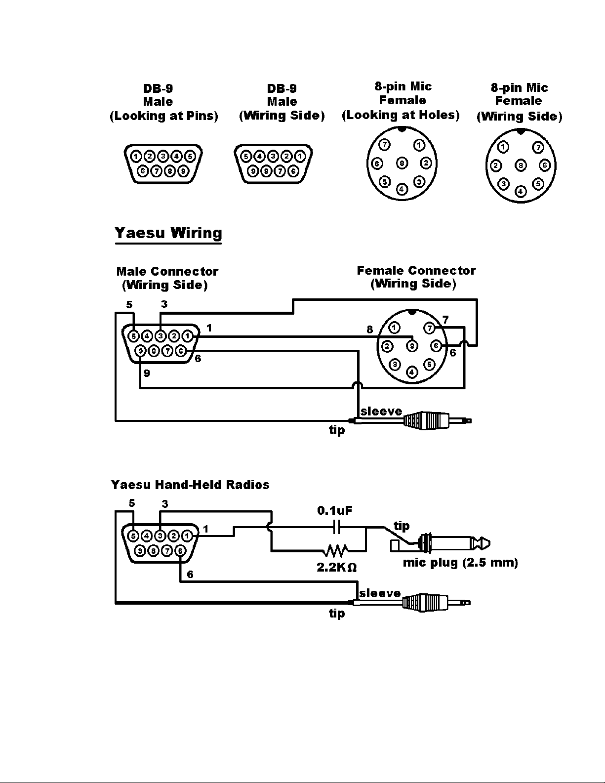
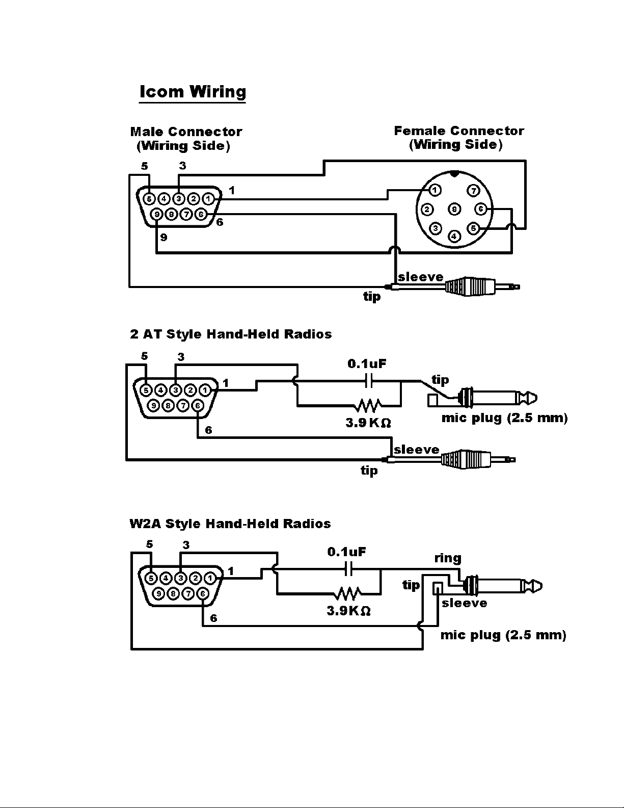
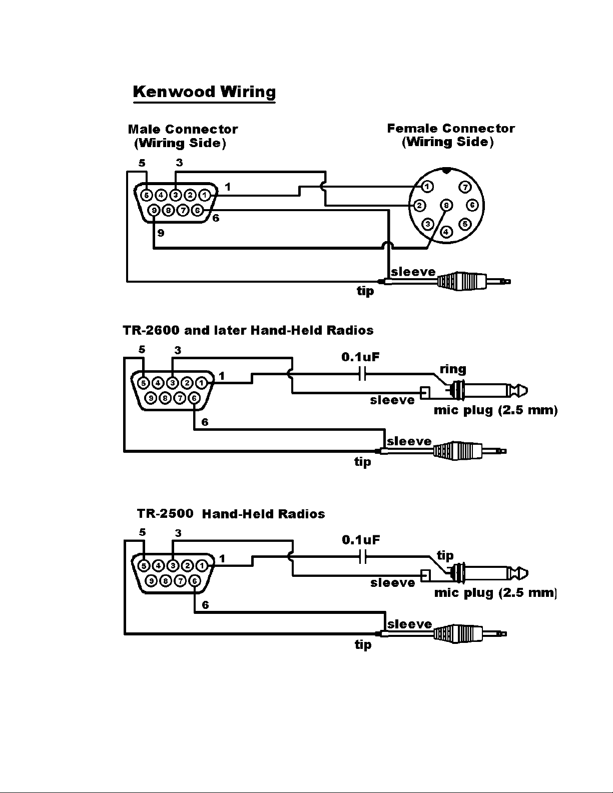
The following diagrams, used for example only, show wiring connections between the
male connector for the MT1200’ “Radio” port and transceivers (including HTs) from
three major manufacturers: Yaesu, Icom, and Kenwood.
These diagrams may also apply to transceivers from other manufacturers, but you need
to check to be sure how your transceiver needs to be wired. See the section on
“Interfacing Hand-Held Radios” in the “Advanced Installation” appendix for further
information.
323334
Page 41
Page 42
Page 43
35
Page 44

Your Transceiver’s Microphone Connections to Your MT1200.
For the microphone on your transceiver, you may wish to make notes of the following
connections, which you will use, for wiring your assembly:
identify and make a note of the microphone input (which will be wired to pin 1,
•
transmit audio on the MT1200’ DSUB-9 “Radio” port),
identify and make a note of the PTT or STBY connection (which will be wired to
•
pin 3, Push-to-Talk on the MT1200’ DSUB-9 “Radio” port),
for base or mobile (but not hand-held) transceivers, identify and make a note of
•
the ground connection (which, optionally, may be wired to pin 9, one of the
ground pins on the MT1200’ DSUB-9 “Radio” port, or left unconnected).
Your Transceiver’s Speaker Jack Connections to Your MT1200
For the speaker jack on your transceiver, make a note of the following connections,
which you will use for wiring your assembly:
• identify and make a note of the connector to your external speaker plug (which
will be wired to pin 5, receive audio on the MT1200’ DSUB-9 “Radio” port),
• identify and make a note of the connector to your external speaker plug (which
will be wired to pin 6, one of the ground pins on the MT1200’ DSUB-9 “Radio”
port).
Constructing the Cable Assembly
As you construct your cable assembly, it may be helpful to refer to the diagram on page.
Important: As shown in the diagram immediately below, looking at the rear panel, the
pins in the MT1200’ female DSUB-9 “Radio” connector are numbered from the upper
right (pin 1) to the lower left (pin 9). As you connect wires to pins on the DSUB-9
connector on your cable, you need to be sure to connect to the correct pins.
As shown in the diagram below, if you look at the solder side (wiring side) of the male
DSUB-9 connector, the pins are numbered (again) from upper right (pin1), to lower
left (pin 9).
36
Page 45

Similarly, when working with a typical 8-pin Mic connector where you know the pin
numbers of pins, you need to consider which way you are looking at the connector
(looking at pins/sockets or looking at the wiring side, where the wires are actually
connected).
Hint: Make notes of which wires (colors, cables) you use for each connection, so
¾
you will be able to keep track of which connection is which.
To construct your transceiver cable assembly, proceed as follows:
¾ Hint: You may find it easier to wire the male DSUB-9 connector if you first connect it
to the MT1200 and use the MT1200 as a test fixture. This may also keep the male
pins straight if you apply too much heat and soften the plastic in the male connector.
A shielded cable must be used with the shield properly terminated 360° to the
connector.
Instructions for making a cable assembly using the supplied foil shielded cable and
metalized plastic back shell follow:
1. Strip cable outer covering back enough to expose enough metalized plastic foil.
Do not cut or rip foil.
2. Carefully loosen the drain wire and foil from around the insulated wires.
3. You will need to build up the diameter of the cable, where it enters the back shell,
with any type of tape or sleeve, so that when the metalized plastic shell halves
are screwed together they will hold the cable as strain relief and press against
the metal foil.
4. Discard the metal strain relief pieces and screws that go with them—they are of
no use.
5. Connect wires as needed to terminals of connector. Keep track of which wire is
connected to which terminal.
6. Carefully fold the metalized foil back over the cable and Z-fold it so the metal side
of the foil is exposed to the connector back shell at the entrance area. Spread the
foil over the cable so you get as much coverage as possible (you will not get 360
° coverage, but do the best you can).
7. Place the drain wire in the gap where you can not get foil coverage.
8. Place one of the shaped washers on each of the long, half-threaded screws, so
they are next to the head of the screw (with the bent ends of the washers facing
away from the heads of the screws).
37
Page 46

9. Now place the metalized plastic shell halves together over the connector and
cable, with the (2) two long half-threaded screws and two shaped washers, to
attach the whole assembly to the MT1200.
10.When you screw the two halves together there should be enough compression to
hold the cable in place and there should be solid contact between the metal side
of the foil and the metalized back shell. See figure below.
11.If your radio is equipped with a single metal connector, then this same cable with
connector attachment technique should be used. Otherwise follow the wiring
directions that follow.
Wiring between your Transceiver Microphone and your MT1200:
Follow the notes taken above and wire the cable assembly in the following order:
Step 1. Using a user-supplied microphone connector appropriate for your transceiver
and the notes taken above, attach wires as follows:
Attach the wire from pin 1 (transmit audio) on the DSUB-9 to the
•
microphone connector’s transmit audio input pin,
38
Page 47

Attach the wire from pin 3 (push-to-talk) on the DSUB-9 to the
•
microphone connector’s PTT pin,
(Optional) for base or mobile units, attach the wire from pin 9 (one path
•
to ground) on the DSUB-9 to the ground pin on the microphone
connector.
Connecting your Transceiver’s Speaker Plug to Your MT1200
Use an appropriate third party speaker plug and the notes taken earlier to do the
following wiring to the DSUB-9 cable assembly:
Step 1. Locate the wire that connects to the audio of the external speaker plug and
attach it to the wire from pin 5 on the DSUB-9 (Receive Audio)
Step 2. Locate the wire that connects to the ground of the external speaker jack and
attach it to the wire from pin 6 on the DSUB-9 (Ground)
This is all you need to do to wire the speaker plug part of the assembly.
Important: Keep your wiring notes for future reference.
This completes the construction of your transceiver cable assembly. Now it needs to be
connected.
Connecting Your Transceiver Cable Assembly
Now you are ready to use this cable assembly to finish assembling your packet radio
station.
Step 1. Check to be sure all the parts of your completed cable assembly are properly
fastened and ready for connection to your transceiver and your MT1200.
Step 2. Turn OFF all power.
Step 3. Plug the male DSUB-9 connector on the cable into the female DSUB-9
connector on the MT1200’ “Radio” port,
Step 4. Secure the male DSUB-9 connector on the cable to the female DSUB-9
connector on the MT1200’ “Radio” port, by screwing the two long, halfthreaded screws into the threaded nuts on each side of the MT1200’ “Radio”
port,
39
Page 48

Step 5. Plug both the microphone connector and the external speaker jack into your
transceiver.
Adjusting the Receive Volume of Your Transceiver
To adjust the receive volume of your transceiver to the proper level (or to confirm that it
is already set at the proper level), do the following:
Step 1. Turn ON your computer (with your transceiver OFF),
Step 2. Start your terminal program,
Step 3. Turn ON your MT1200,
Step 4. If not already done, set the MT1200’ baud (ABAUD) and CALLSIGN,
Step 5. Turn ON your transceiver and open the squelch control (turn it fully counter-
clockwise),
Step 6. Slowly turn the transceiver’s receive volume up until the RCV LED (receive
indicator) on the MT1200 lights up (turns ON),
Step 7. Increase the transceiver’s receive volume control slightly above the point at
which the MT1200’ RCV LED lit up (turned ON),
Step 8. Slowly turn the transceiver’s squelch control clockwise until the MT1200’ RCV
LED goes OUT (turns OFF),
Now the receive volume control on your transceiver is properly adjusted for sending
signals to your MT1200.
Your MT1200 is now installed and ready to use. You may now go to the “Getting
Started” chapter, to learn how to do the basic operations with your MT1200.
If you do not see the receive LED light, check the cabling between the radio and the
MT1200. Also, until it has been initialized from the computer, the MT1200 will not show
ANY indication of receiving.
If you connected to a fixed level (unsquelched) receive audio from the radio, the receive
LED on the MT1200 may remain on all of the time. In this case, set the parameter CD to
SOFTWARE. Then, the receive LED will not light until valid packets are heard. (see CD
in the commands section)
Transmit level adjustment
The 1200-baud data drive level (transmit audio voltage, TXA) from the MT1200 to your
radio is adjusted digitally, using your keyboard and the transmit level (XMITLVL) or the
40
Page 49

calibrate (CAL) command. Previous models used a set of jumpers and an analog
potentiometer (pot) to set this level. With the MT1200, no jumpers are used, just a
command.
You should adjust the drive level to provide about 3 to 3.5 kHz of deviation with your
radio. If you don’t have access to a deviation meter, adjust drive so your packet
transmissions generate about the same audio sound as packets heard from other
stations.
The XMITLVL command has a parameter default value of 100; this corresponds to a
drive voltage of about 50 mV. You may change this level by increasing the
parameter/count. For counts below 256, the voltage is increased in 0.5 mV steps; above
that, the drive increases roughly 15 mV per step.
For details, see the description of the XMITLVL command in the “Command Reference.”
Alternatively, you may use the calibrate command (CAL) which has a zoom feature; that
is, you can hold down the ‘-’ or ‘+’ key to decrease or increase the voltage (as you watch
a meter or listen). See the commands section for more detail on these commands. The
MT1200 must be in TERMINAL interface mode to access CALIBRATE mode.
For more information on installation topics, see the appendices.
41
Page 50

Getting Started
This chapter gives you important information and examples to get you started using
your packet radio station.
We assume you have installed your station and familiarized yourself with the use of with
your MT1200, as covered in the chapters on “Installing your MT1200”.
If you have not yet installed your station, we suggest that you do so before continuing
with this chapter.
Material covered here includes diagrams, explanations, and mini-tutorials on:
• the front panel of the MT1200,
• beginning a session,
• giving commands and transmitting data,
• monitoring transmissions from nearby packet radio stations, and
• connecting to another station and initiating a conversation, and
• configuring GPS settings and beacon intervals.
Reading this chapter (or just skimming the material, if you are already familiar with the
topics) will also help you use the following chapters on different modes of use of the
MT1200, the “Command Reference” chapter, and any appendices that are relevant to
your needs.
42
Page 51

The Front Panel of the MT1200
You have already used the POWER switch on the MT1200 to turn power on and off.
This is a good time to get familiar with all the indicators on the front panel of the
MT1200.
The following diagram shows the placement and function of the controls and indicators
on the front of your MT1200, as well as a brief explanation of each:
GPS
Power Switch PWR TX RX CON STA
The Power Switch turns power on or off in the MT1200.
The GREEN PWR LED indicator shows when the MT1200 is powered on.
The RED TX LED lights when transmitting.
The GREEN RX LED lights when receiving signals.
The GREEN CON LED lights when a packet connection is in progress with another
packet station.
The GREEN STA LED lights when packets sent to a connected packet station have not
yet been acknowledged by that station.
The RED GPS LED is ON, when the Internal GPS is enabled, but a connected GPS
antenna is not detected. This LED flashes when the internal GPS is enabled, and GPS
antenna is detected, but valid GPS position has not yet been calculated.
The GREEN GPS LED flashes once per second when valid GPS position is known.
NOTE: All front panel LEDs will remain OFF if the LED command is set to OFF.
43
Page 52

Beginning a Session
The steps involved in starting a session are covered in detail in the “Installing your
MT1200” chapter.
Start HyperTerminal, select the MT1200 icon, and turn on the MT1200.
Once your initial setup is completed (including giving a CALLSIGN to your MT1200 and
setting other parameters as needed), the first thing you will see each time you start a
new session is a sign-on message from the MT1200 (sent to HyperTerminal and
displayed on your computer screen) such as the following:
KANTRONICS MT1200 VERSION 1.07064
SERIAL NUMBER xxxxxxxxxx
(C) COPYRIGHT 2007 BY KANTRONICS INC. ALL RIGHTS RESERVED.
DUPLICATION PROHIBITED WITHOUT PERMISSION OF KANTRONICS.
cmd:
The last line of this message (“cmd:”) is the MT1200’ report that it is in “Command”
mode, which means that it is now expecting information from HyperTerminal to be
commands for it (the MT1200) to interpret and carry out. Before learning about the
specific commands you can give the MT1200, it is important to keep in mind the
difference between giving the MT1200 commands and giving the MT1200 data that is to
be transmitted.
Giving Commands and Transmitting Data
The MT1200 will react to data received from HyperTerminal (or any other source) either
as a command to follow or as information to transmit.
Command Mode
When in the “COMMAND” mode of communication, the MT1200 will interpret data
received from HyperTerminal (or any other source) as being a command to process, not
as data to transmit. To instruct your MT1200 to connect, to disconnect, or to change any
of the operating parameters in the MT1200 you must be in the COMMAND mode.
When placed in COMMAND mode (and ready to receive the next command) the
MT1200 sends a “cmd:” prompt for display on the computer’s screen.
Converse (Conversation) Mode
When in “CONVERS” (conversation) mode, the MT1200 will interpret data received
from HyperTerminal (or any other source) as data to transmit. In “CONVERS” mode, the
MT1200 interprets most characters as information to be transmitted, while interpreting
certain pre-defined characters (which the user can change) as control characters rather
44
Page 53

than as data to be sent. For example, a “backspace” character causes a backspace and
is not transmitted.
The MT1200 will automatically switch to the CONVERS mode for you when you connect
to someone or when someone connects to you and will return to the COMMAND mode
when a disconnect occurs. When you are in COMMAND mode, you may switch to
CONVERS mode just by giving the command K (or CONVERS). If you are in the
CONVERS mode and want to force your MT1200 back to the COMMAND mode, you
type a <Ctrl+C>.
TRANS (Transparent) Mode
A second way to transmit data is to instruct the MT1200 to ignore the “control
characters” (e.g., “backspace”) and just transmit every character as data. This is called
the “TRANS” (transparent) mode of communication. For example, if data received by
the MT1200 for transmission in TRANS mode includes “backspace” characters (i.e.,
characters that would cause a backspace in CONVERS mode), the MT1200 will
transmit the backspace characters as part of the data.
Before you can switch to TRANS mode, you need to set INTFACE to TERMINAL
instead of NEWUSER. (This is because, as described in the next section, the TRANS
command is not a NEWUSER command.) To get out of TRANS mode and back to
COMMAND mode, enter “<Ctrl+C> three times, with a pause of less than one second
between each entry.
Check Your MT1200’ Version Number and ID
To check your MT1200’ version number and ID all you need to do is ask to see the
current setting of the command called VERSION:
Step 1. Go to COMMAND mode (if you are not already there).
Step 2. Type “VERSION” (or the short form, “V”) and press the ENTER key to enter
the command.
Step 3. The MT1200 will send its version number and other ID information for display
on your monitor.
Get Help
To see a one-line explanation of any command that is currently available:
Step 1. Go to COMMAND mode (if you are not already there).
Step 2. Type “HELP,” (or “?”) followed by one or more spaces and the name of the
command for which you want help.
45
Page 54

Step 3. The MT1200 will send a short “HELP” message about the command, for
display on your monitor.
View Current Values of Parameters
To see the current value of parameter(s) for any variable (other than the “immediate”
commands, like CONVERS, that are simple actions, not settings):
Step 1. Go to COMMAND mode, as described above (if you are not already there).
Step 2. Type the name of the command for which you want to see current parameter
value(s).
Step 3. The MT1200 will send a message consisting of the name of the command
and the value(s) of its parameters for display on your monitor. For example, if
you type INTFACE, you will see INTFACE TERMINAL.
As explained in the “Command Reference” chapter, the DISPLAY command can be
used to see current values of ALL or a selected sub-sets of commands.
Change the Value of a Parameter
To change the current value of parameter(s) for any variable (other than the
“immediate” commands, like CONVERS, that are simple actions, not settings):
Step 1. Go to COMMAND mode, as described above (if you are not already there).
Step 2. Type the name of the command for which you want to change the current
parameter value(s), type one or more spaces, and enter the new value(s) you
want for the parameter(s) for the command.
Step 3. The MT1200 will immediately change the value(s) to the values(s) you have
just entered.
If you enter a value that is not possible (e.g., INTFACE MOON), you will get an error
message (“EH?”). “EH?” simply means that the command you entered was not
understood.
To confirm that the current value(s) is what you want, enter the name of the command
and press ENTER. The MT1200 will send a message consisting of the name of the
command and the current value(s) of its parameter(s) for display on your monitor.
46
Page 55

Monitor Communications From Nearby Stations
A good way to start using your packet radio station is to monitor communications from
nearby stations.
Amateur packet-radio activity is usually at VHF, on 2 meters, with 145.010 MHz being
the most common packet-radio frequency. APRS reporting stations use 144.390 MHz.
Most packet on VHF channels is at 1200 baud.
To monitor communications from nearby stations (after you have tuned in to an
appropriate frequency):
Step 1. Set the command MONITOR to ON (if it is not already ON).
Step 2. Disconnect from any other station.
Step 3. As packets are received, you will see them displayed on your screen. A
typical received packet might look like this:
NØKN>KBØNYK:
Hi Mike. How are you today?
The first line is the header line, and shows the callsigns of the stations talking
and the following line(s) are the actual message that was sent. In the example,
NØKN is the transmitting station, and KBØNYK is the receiving station. You may
see the RCV LED light at times, indicating a signal is being received, but nothing
displays on your screen. This is normal and may be the result of the settings of
the monitoring commands, which are discussed in detail in the MT1200
Command Reference.
As you monitor, you will begin to learn about other packet stations in your area and then
you will probably want to try to connect to one of them.
Communicate Directly with a Nearby Station
Now you are ready to carry on a two-way conversation with another station. Here we
will see exactly what you need to do to connect to and converse with another station.
Let’s say that you decide to connect to KBØNYK. The steps needed are as follows:
Step 1. First, be sure you have the MT1200 in command mode. To do this, type
<Ctrl+C> and then press return. You should see a command prompt (cmd:).
Step 2. Now you use the CONNECT command. To connect to KBØNYK, you would
simply type CONNECT KBØNYK and press return, just as you did in the
sample connect to your mailbox.
47
Page 56

In some cases you may need to use a relay station (called a digipeater) to
contact another station. This is similar to using a voice repeater when the station
you want to talk to is out of simplex range. To connect to a station using
digipeaters, you still use the CONNECT command, but you must also specify the
callsigns (or aliases) of the digipeaters that must be used. For instance, if you
need to use two digipeaters with callsigns of WØXI and KCØCON in order to
connect to KBØNYK, you would give the connect command as “CONNECT
KBØNYK VIA WØXI,KCØCON”
Step 3. Once the connection has been made, you’ll receive a message back on your
screen from the MT1200 that says *** CONNECTED to KBØNYK (or, if you
are using relay stations, *** CONNECTED to KBØNYK via WØXI, KCØCON).
At that point you are ready to start talking to the other station since the
MT1200 has already automatically switched into the CONVERS mode.
Step 4. After you have completed your conversation, simply press <Ctrl+C> to return
your MT1200 to the command mode (“cmd:” will be displayed) and then you
can instruct your MT1200 to disconnect as you did above with the mailbox, by
entering D (or the full form, DISCONNE) and return.
As you begin working with your MT1200 packet radio station, other topics that you may
wish to explore (with the help of other sections of this manual) include:
• doing hard and soft resets,
• communicating via relays with a distant station,
• using network nodes, and
• beaconing GPS data.
This concludes a quick tour of basic uses of your MT1200. With just these basics, you
can do a lot, but you have a great deal more power if you want to explore the full
possibilities.
For more information on all the topics we have covered here, and more, see the
following chapters in this manual.
48
Page 57

Modes of Operation
This chapter covers the major ways in which you may use your MT1200 TNC. For
details on particular commands, see the “Command Reference” chapter.
Packet Mode
Protocol for Amateur Packet Radio: AX.25
The mode commonly called PACKET is defined by the protocol called AX.25. The
details of the inner workings can be found in a book titled “AX.25 Amateur Packet-Radio
Link-Layer Protocol”, which is available from the ARRL. Most TNC users will not need to
or care to go into the details. The TNC takes care of the nitty gritty work for you,
although there are parameters you can set that determine how efficiently some of that
work is done.
Command Mode
In order to change parameters, or give any other instructions to the TNC, you must be in
Command Mode. This is the mode you will be in when you first turn on the TNC or after
resetting it.
Once you have left Command Mode for any reason, and now wish to return to
command mode, you will need to enter a special character or characters. The
parameter called COMMAND determines what special character you will use to return
to Command Mode. This comes defaulted as a <Ctrl+C> (i.e., while holding down the
control key, press “C”, then release both keys).
Whenever you enter Command Mode the TNC will send a prompt to your screen that
looks like this:
cmd:
Connected vs. Unproto
There are two ways to send data in packet radio, connected or unproto (unconnected).
In the Connected Mode you first establish a connection. Then your TNC will send
packets to that specific station and expects acknowledgments in return. If an
acknowledgment is not received, the TNC will resend the data (depending on the setting
of AX25L2V2, it may send a poll first). The RETRY parameter will determine how many
times this is done before the connection is lost due to bad conditions. If the
acknowledgment is received, the TNC is happy and will send more data when available.
49
Page 58

Therefore the Connected Mode, barring impossible conditions, assures that the station
you are connected to will receive everything you say, and in the order you say it.
In the Unproto Mode, when your TNC sends a packet, no acknowledgment is expected
and no retries are attempted. This mode is often used for calling CQ, for transmitting
beacons, and for informal round table chats.
Monitoring and Calling CQ
If you set the MONITOR command to ON, you will see other station’s packets on your
screen. You will notice two callsigns at the beginning of each packet separated by a “>”.
The first callsign is the station the packet is from, and the second callsign is the station
the packet is to. An Unproto packet may have a name or CQ for the second callsign.
To set what will be seen as the “to” callsign for Unproto packets you send, you use the
UNPROTO command. This comes defaulted as CQ.
In order to call CQ you must get into the Convers Mode, so that what you are typing to
the TNC will be interpreted as data to be sent out on the air and not as commands. To
do this type:
The <CR> indicates a “carriage return” or pressing the “ENTER” key on your keyboard.
Now anything you type will be packetized and sent out on the air. Remember to get
back to Command Mode you enter a <Ctrl+C> (default) by holding down the Control key
while pressing “C”. You will be going between Command and Convers Modes
depending on whether you want to talk to the TNC or have the TNC packetize what you
type to go out on the air.
Flow Control
The flow control commands insure that the TNC gets everything that is sent to it by the
computer and that the computer gets everything the TNC sends it. When the computer
sends the TNC data, the TNC stores this data in a buffer until it can packetize it, send it,
and get acknowledgments. Similarly, when the TNC sends the computer data, the
computer stores the data in a buffer until it can be processed, stored to disk, sent to
printer, or whatever.
This buffer area is of limited size; if more data is sent than will fit in the buffer the extra
data will be lost. To make sure each device gets all the data it should from the other
device, the two devices can tell each other to start and stop sending data. This is called
Flow Control and it can be accomplished in either of two ways, via software or via
hardware.
K<CR>
50
Page 59

Which way you implement this depends on the capabilities of your computer
communications program and personal preference. The cable between your computer
and TNC must also be wired appropriately.
Software Flow Control
Software flow control sends special characters on the TXD and RXD lines of the RS232
cable. These are the same lines used for sending regular data between the TNC and
computer. Software flow control normally sends a <Ctrl+S> to stop data and a <Ctrl+Q>
to restart data. When a buffer gets close to full, the device will send a <Ctrl+S> and
expect the other device to stop. When the buffer gets nearly empty, it will send a
<Ctrl+Q> to tell the other device to send more data. How full or empty a buffer is, when
the special characters are sent, is determined by the program. But, since the regular
data lines are being used, a <Ctrl+S> sent as data from the keyboard will also stop data
from the TNC. And likewise, if there is a <Ctrl+S> in a file being sent, data flow from the
TNC will stop until a <Ctrl+Q> is received.
XFLOW needs to be turned ON for the TNC to use software flow control. XOFF
determines the character sent by the TNC to stop the flow of data from the computer,
and the XON character restarts the flow. The TNC expects the computer to send the
STOP character to stop data to the computer and the START character to restart data.
To use software flow control these commands would be set as follows: XFLOW ON,
XOFF $13, XON $11, STOP $13, START $11. (Default settings.)
Two commands are provided to make it possible to send and/or receive these special
characters in Transparent Mode and still use software flow control. TXFLOW enables
flow control sent by the TNC to the computer and TRFLOW enables the TNC to
recognize flow control sent by the computer. If both these commands are ON (and the
above commands are set as stated) then software flow control will take place in both
directions, to and from the TNC and computer.
If you are in Transparent Mode sending a file, the computer does not need to tell the
TNC to stop and start (since you are sending the file). By turning TRFLOW OFF and
TXFLOW ON, the TNC will accept START and STOP characters embedded in the file
and send them along to the radio as data. Meanwhile, the TNC can send the XOFF and
XON characters to the computer to control the flow of data from the computer. When
receiving a file, turn TRFLOW ON and TXFLOW OFF; the computer will accept all data
and use START and STOP characters to control the flow of data from the TNC.
Hardware Flow Control
Hardware flow control monitors the voltages on the RTS and CTS pins of the RS232
cable. Therefore these two pins must be wired between your TNC and a connected
computer. The TNC holds CTS high as long as it can receive data. Once its buffer gets
full, it pulls this line low. The computer program monitors this line. When it is pulled low,
it knows to stop sending data. When the line is again pulled high by the TNC, the
computer program will restart sending data. On the other hand the computer holds RTS
51
Page 60

high as long as it can receive data and pulls it low to tell the TNC to stop sending data.
The TNC always uses hardware flow control, so only wire the RTS and CTS pins if your
computer program is also using hardware flow control.
HyperTerminal uses hardware flow control in its default settings, but some
communication software does not.
Convers Mode vs. Transparent Mode
In the Convers Mode there are many special characters. To list a few:
Command Default Description
SENDPAC <Ctrl+M> Causes a packet to be formed
DELETE <Ctrl+H> Backspace character
REDISPLAY <Ctrl+R> Redisplays the keyboard buffer
CANLINE <Ctrl+X> Cancels a line
STOP <Ctrl+S> Stops output from TNC to computer
PASS <Ctrl+V> Pass a special character
These characters are all very useful when having a packet conversation with someone.
If you want to send a packet you hit the return. If you make a mistake you can erase
characters, using the delete or backspace key, or kill the whole line with <Ctrl+X>. And
if you really want to transmit one of these characters, you can always precede it with a
PASS character.
Transparent Mode was designed for the sending of files, whether they be ASCII data
files or program files. Special characters have no meaning to the TNC in transparent
mode, they are just characters to be put in a packet and sent to the radio.
In Transparent Mode, a SENDPAC character will not cause data to be formed into
packets; instead, packets are formed at a rate that is set by PACTIME.
All monitor commands are treated as OFF in Transparent Mode. All you will see is what
is being sent to you. You would probably want to set USERS to 1 so no one interferes
with the transfer. The setting of ECHO is also ignored. Even if ECHO is ON Transparent
Mode will not echo to the attached terminal. Some programs allow for local echoing to
the screen while uploading.
Exiting Transparent Mode
Getting into the Transparent Mode is easy: you just type a “t” in Command Mode. But
since Transparent Mode allows the sending of all characters you can not get out of
Transparent Mode by just typing a <Ctrl+C> (COMMAND character) as in Convers
Mode. In order to get out of Transparent Mode, you must follow a special sequence, or
use a modem break if your program supports one. The special sequence must be
52
Page 61

followed precisely. This example assumes the COMMAND character is <Ctrl+C> and
CMDTIME is 1 second:
• Wait at least 1 second since the last character was sent from the computer to the
TNC
• Type a <Ctrl+C>
• Within 1 second type a second <Ctrl+C>
• Within 1 second type a third <Ctrl+C>
• Wait 1 second and the cmd: prompt should appear
If the guard time of one second before and after the three <Ctrl+C>s is not there, the
TNC assumes that they are data and sends them to the radio, so be sure to allow at
least one full second before and after the three <Ctrl+C>s.
In most cases, you can simply press and the CONTROL key, then press the C key three
times quickly, then release the CONTROL key.
53
Page 62

Linesub mode
LINESUB Protocol Description
The LSUB mode of operation provides a method of transmitting-and receiving raw
ASCII data via a radio. Data is sent and received in a totally transparent fashion,
allowing all ASCII characters to be utilized (hex 00 through hex FF). There is no
addressing, error-detection or automatic retransmission of the data. When the receiving
modem detects the proper Start-of-Data sequence generated by the transmitting
modem, it will output the data that follows to its; serial port. At the end of the received
data there is an End-of-Data sequence that permits the receiving modem to recognize
the end of the data and quit translating the receiver audio. This allows the modems to
operate with open squelch audio from the radios. Since the protocol constitutes a very
small portion of the transmission, the effective data throughput is very nearly that of the
radio baud rate (1200).
Commands Used
TXDELAY - The TXDELAY (TXD) command determines how long the modem must key
the Push-to-Talk line of the radio before sending data. This time will have to be
determined experimentally since it will vary from radio to radio. If the TXD is set too
short, the data transmitted will be garbled and not received by other units in the system.
Setting TXD too long will reduce channel capacity.
PACTIME - The PACTIME parameter determines how long the modem will wait after
receiving data to be transmitted from the DTE before beginning the radio key-up
sequence. Normally, this parameter should be set to AFTER 1 (100 ms.) in order to
minimize "dead-air" time on the system.
PERSIST and SLOTTIME - These parameters determine how aggressively the modem
will attempt to access a multi-user channel based on carrier detect. See KPC-series
manual for a full explanation of these parameters.
Entering LSUB Mode
When you have made any desired changes from the default settings for the above
parameters, use the INTFACE command to begin LSUB operation. Set the INTFACE
command to LINESUB:
cmd:INTFACE LINESUB <cr>
54
Page 63

and turn the unit off and then back on. Be aware that there is no data flow control.
Exiting LSUB Mode
If you want to exit LSUB mode to "fine tune" parameter settings (or for any other
reason), the Command mode of the modem can be regained by using the transparent
data escape sequence, i.e., by sending a series of three control-Cs (unless a different
control character has been defined). (See TRANS command in the Reference Manual).
TUP mode (Transparent Unproto Packet)
TUP Mode Description
The TUP mode protocol utilizes the Unproto mode of the AX.25 protocol, allowing
digipeaters (VIA path specified with UNPROTO command) to be used in order to
effectively extend the range of a radio data system beyond simplex distance. This
protocol uses the standard AX.25 CRC-16 error-checking to provide a high degree of
data integrity. Data is sent and received in a totally transparent fashion, allowing all
ASCII characters to be utilized (hex 00 through hex FF). I. Radio transmission is based on
the PACTIME AFTER parameter setting of the modem, the setting of the carrier detect
method, and the settings of the slot and persist channel access algorithm. Any data that
is received by the modem via the radio is output to the serial port only if it contains no
detectable errors. The received data will be exactly the same as the data that was sent
to the input serial port of the transmitting mode, without any address headers or added
formatting of the data. The modem is capable of selectively filtering monitored data from
or to different modem addresses using the BUDLIST command.
If digipeaters must be used to extend the range of the system, the information frame
sent by any modems in the system will be output to the serial ports of the receiving
modems only once, regardless of how many times it was received correctly. Also, data
sent by any modem will not be decoded by itself when the data is digipeated. The TUP
mode protocol provides an automatic "Time to Live" timer that inhibits any modem from
transmitting or receiving additional data until sufficient time has expired to allow inprogress data to travel through all the digipeaters specified in the UNPROTO field of the
originating modem. Since the time for a given packet to travel the entire UNPROTO
path may vary due to the presence of other signals or noise, TUPTIME is used to
impose an additional delay time, if needed, during which each modem will be inhibited
from decoding or transmitting new data. This setting can be determined experimentally.
It is important to note that TUPTIME applies only to the receiving modems and should
55
Page 64

be set to the same value at all sites. It is the responsibility of the host system to insure
that additional data is not transmitted until sufficient time has elapsed to allow data to
travel to the last digipeater and the response, if any, to travel back to the host. Note that
the automatic "Time to Live" timer and the TUPTIME timer are only in effect if packets
are being digipeated.
Commands Used
Basic TUP Operation involves just a few commands:
MYCALL - The MYCALL command determines the MODEM address. This must be
entered after the autobaud routine has detected an asterisk (*).
TXDELAY - The TXDELAY (TXD) command determines how long the modem will
assert the Push-to- Talk line of the radio before sending data. This time will have to be
determined experimentally since it will vary from radio to radio. If the TXD is set too
short, the data transmitted will not be received by other units in the system. Setting TXD
too long will reduce channel capacity. NOTE: Since TXD is used in the computation of
the automatic timer used to inhibit transmission until a digipeated packet has had time
to reach its destination, TXD must be set to the same value in all modems in the system
PACTIME - The PACTIME parameter determines how long the modem will wait after
receiving data to be transmitted from the DTE before beginning the radio key-up
sequence. Normally, this parameter should be set to AFTER 1 (100 ms) in order to
minimize "dead air" time on the system.
PACLEN - PACLEN sets the maximum size of the data packet(s). Most applications do
not require large amounts of data to be transferred so the default value (128) will
probably be satisfactory, allowing packets up to 128 bytes. If the amount of data to be
sent exceeds the PACLEN parameter setting, the transmission will be composed of
multiple packets containing the data.
PERSIST and SLOTTIME - These parameters determine how aggressively the modem
will attempt to access a multi-user channel based on carrier detect. See KPC-series
manual for a full explanation of these parameters.
Entering TUP Mode
Use the INTFACE command to begin TUP operation. Set the INTFACE command to
TUP:
cmd:INTFACE TUP <cr>
and turn the unit off and then back on.
56
Page 65

Exiting TUP Mode
Poll Mode
Poll Mode Protocol Description
If you want to exit the TUP mode to "fine tune" parameter settings (or for any other
reason), the Command mode of the modem can be regained by using the transparent
data escape sequence, i.e., by sending a series of three control-Cs (unless a different
control character for COMMAND has been defined). (See TRANS command in the
Reference manual).
The POLL mode is generally used in system applications that implement a polledresponse protocol between a central site (Control Site) and one or more remote
locations (Remote Site). The POLL mode is similar to the TUP mode since it uses a
data transparent broadcast mode and a packet protocol with CRC-16 error-checking to
insure the integrity of the received data. All ASCII characters (hex 00 through FF) can
be transmitted and received. The POLL mode differs from TUP mode by allowing an
application program to address specific locations without changing any modem
parameters. All data sent by the application program at the central sit must begin with
the address (POLLID) of the intended remote modem. When any remote modem
receives data from the radio, the data is checked for errors and the received POLLID is
compared with its own POLLID. If they match, the POLLID is stripped and the data that
follows is sent to the serial port. All data received by the central site from the remote
location will arrive with the POLLID of the remote site automatically attached to the
beginning of the data.
It is the responsibility of the application program to: (1) address data to be sent to the
remote sites, (2) determine if the data was received, and (3) recognize responses that
contain the remote site's POLLID and data. Digipeating is not allowed
Commands Used
Each modem is set up differently depending upon whether it is to be a Control modem
or a Remote modem.
Control Site
Control Site Configuration - The POLLID command in the Control modem must be set
to 0000 and the INTFACE command must be set to POLL. (See "Entering POLL Mode"
below.)
57
Page 66

Control Site Transmit Format - All data sent to the Control modem via the RS232
serial port must begin with a POLLID (four digit remote address between 0001-9999)
and be followed immediately by the poll data. The data sent by the application to the
Control modem must contain less than PACLEN bytes. If the poll data contains more
characters than allowed by the setting of the PACLEN command, the data will be
fragmented and multiple packets will be formed and transmitted by the modem. These
additional packets will contain only the balance of the data received by the modem.
Since these packets do not begin with a POLLID, they will be ignored by all Remote
modems.
Control Site Receive Format - All Remote transmissions received by the Control
modem shall consist of the Remote POLLID followed immediately by the Remote data.
Both POLLID and data will be sent to the control DTE via the RS232 port.
Remote Site
Remote Site Configuration - The POLLID command in each of the Remote modems
must be set to a different number between 0001 and 9999. This assures that data is
received by just one remote device.
The INTFACE command in each modem must be set to POLL. (See "Entering POLL
Mode" below.)
Remote Site Transmit Format - Remote sites generally do not have much computing
capacity. . Therefore, the transmitted format of the data is, of necessity, straightforward.
All data recelved via the serial port will be formed into packets and transmitted with the
address (POLLID) attached to the beginning of each data packet.
Remote Site Receive Format - All data received by the Remote via the radio is first
examined for errors using a CRC-16 error-checking algorithm. Data packets that contain
errors are discarded. If the data contains no errors, it is then checked for a match of the
received POLLID and its own POLLID. If there is not a match, the data is discarded. If
there is a match, the POLLID is stripped and the raw data is passed to the RS-232
serial port for processing. The received data format will be exactly the same as the data
sent to the Control Modem by the application program.
The CONMODE parameter affects when data will be sent in Poll Mode.
If CONMODE is set to CONYERS (default), data will be transmitted when any of the
following conditions is met:
The SENDPAC character is received by the modem. The default SENDPAC character
is a carriage return and can be changed to suit an existing application. The SENDPAC
character can be either stripped or appended to the data by setting the CR command
ON to append, or OFF to strip.
58
Page 67

CAUTION: MASTER (Control Site) operation will be unusable if PACLEN is exceeded
since each packet of data sent MUST begin with a Slave (Remote Site) POLLID (0001-
9999). Remote transmission may exceed the setting of PACLEN since each packet
transmitted from the Remote will contain the proper POLLID. If fragmentation of data
occurs, the application program is responsible for reconstructing the data. PACLEN
determines the maximum size of data packets (default 128 characters). Normally, the
amount of data to be transmitted will be considerably less than this.
CPACTIME is on and PACTIME expires. If CPACTIME is ON, data will be periodically
transmitted based on PACTIME timeout.
If CONMODE is set to TRANS, data will be transmitted when PACLEN is exceeded, or
PACTIME expires.
Suggested Settings
Usually, the CONMODE command is set to TRANS and the PACTIME command is set
to AFTER 1. The CONMODE TRANS command makes the modem data transparent to
the Remote device. The PACTIME AFTER 1 command allows the modem to transmit
the data received via the serial port with as little delay as possible. This speeds up the
response time of the system by reducing "dead-air" time.
It is also recommended to set the PACLEN command to zero. This allows the modem to
send a single packet of data to the radio of any size between 1 and the maximum of 256
characters. If the response data from the remote contains more characters than the
PACLEN command allows, the data will be transmitted in multiple packets with the
Remote POLLID automatically attached to the beginning of each data packet. In such a
case, it is the responsibility of the Control Application Program to reassemble the data.
CAUTION: Allowing the Control Site application to send more data than that permitted
by the PACLEN command is the most common cause of failure using the POLL mode.
BE ABSOLUTELY SURE THAT CONTROL SITE TRANSMISSIONS NEVER EXCEED
THE PACLEN LIMIT!
Entering POLL Mode
When you have entered the POLLID of the unit and made any desired changes from the
default settings in the parameters, use the INTFACE command to begin POLL
operation. Set the INTFACE command to POLL:
cmd:INTFACE POLL <cr>
and turn the unit off and then back on.
59
Page 68

Exiting POLL Mode
If you want to exit POLL mode to "fine tune" parameter settings (or for any other
reasons), the command mode of the modem can be regained as follows:
If CONMODE = CONV
Enter: 0000QUIT<cr> (NOTE: QUIT MUST BE IN UPPER CASE)
If CONMODE = TRANS
Use the transparent data escape sequence, i.e., send a series of three control-Cs
(unless a different control character has been defined). (See TRANS command in the
Reference Manual).
Modem Mode
In MODEM mode, the TNC demodulates the audio signal from the radio on port 1 and
passes this data through to its RS232 port unmodified. No “protocol” adjustments are
made to the data; the TNC simply acts as a dumb modem. In other words, it simply
reflects out the RS232 port what it “sees” coming in the radio port. For example, if ASCII
information is received at 1200 baud, the TNC presents your computer with ASCII at
1200 baud. With a simple terminal program running at 1200 baud too, you’d be able to
copy the text.
➔
To place the TNC in modem mode use the INTface command. At the cmd: prompt, type
INT MODEM and return. Then turn your TNC power OFF and back ON.
To leave modem mode, send three Ctrl+C (command) characters to the TNC at 1200
baud. If ABAUD was set to something other than 1200, that setting will remain after you
exit modem mode. Hence it may be convenient for you to set the TNC to 1200 baud
before entering modem mode.
Note: Some computers may lose some of the data stream if a full RS232 cable is used.
This can occur because the RS232 DCD line, which is “tied” to the TNC’s receive LED,
may be cycling up and down. In this case, set CD to EXTERNAL before entering INT
MODEM.
Copying Weather Broadcasts NWS EMWIN
MODEM mode can be used to copy emergency weather broadcasts by the National
Weather Service. The NWS Emergency Managers Weather Information Network
(EMWIN) is a wireless direct-to-computer information service that the National Weather
Service (NWS) provides with help from the Federal Emergency Management Agency.
60
Page 69

The NWS feeds a constant stream of weather information (@ 1200,8,N,1), from around
the world, to a satellite orbiting the Earth. Many cities are coming on line now to capture
this stream and rebroadcast it on fixed VHF commercial FM frequencies just above the
2-meter ham band.
Using your TNC in MODEM mode, with a PC and communications software, you can
copy these broadcasts. The content of the broadcasts may be plain ASCII text
(copyable with HyperTerminal) or graphics. For updated information on EMWIN and
software to copy its modes, search the Internet.
To copy the broadcasts, simply cable together the equipment mentioned above, tune
your VHF FM receiver to the local EMWIN frequency, set the INTFACE command to
MODEM, and follow the text on your PC screen.
KISS Mode
Amateur packet radio communications can use the TCP/IP suite of protocols instead of
AX.25 by switching to KISS mode and running software that supports the KISS code
designed by Phil Karn (see references at end of this section). The KISS protocol
specifies the communication between a TNC and a host (e.g., computer).
KISS Mode allows the TNC to act as a modem and packet assembler/ disassembler
(PAD). In KISS Mode, data processing is shifted from the TNC to a computer running
special software supporting the KISS code designed by Phil Karn. KISS code supports
higher level protocols (i.e. TCP/IP) for sharing computer resources in a network fashion.
Examples of TCP/IP programs are NET, NOS, and JNOS. Also, some networking
software (G8BPQ) requires the KISS Mode of operation.
Technical Note: In the KISS Mode, the TNC simply passes all received data to your
computer, and the computer program is responsible for all processing of that data,
including decisions concerning routing, digipeating, and other control decisions. The
TNC converts the packets of synchronous data being received from the radio link into
packets of asynchronous data to be passed to the computer over the serial port, and
converts the packets of asynchronous data from your computer into the synchronous
format suitable for radio transmission. The TNC retains the responsibility of determining
proper timing for channel access.
To place your TNC in KISS Mode, you must first have the command prompt (cmd:).
Then type INTFACE KISS and press return. And, finally, do a RESET.
After that you will not see any message or any prompt back from the TNC, it will now be
in KISS mode.
61
Page 70

If you turn your unit off while it is it INTERFACE KISS mode, it will still be in KISS mode
when you turn it back on. To get out of KISS mode:
• perform a hard reset, or
• use the KISS exit command (available in KISS software while in KISS mode), or
• send the C0 FF C0 (hexadecimal) sequence from your keyboard.
To send the C0 FF C0 sequence, in decimal values, from your keyboard (using the
number keypad on a PC compatible computer keyboard):
1. Press and HOLD the ALT key. Type the numbers 192 from the numeric
KEYPAD. Release the ALT key.
2. Press and HOLD the ALT key. Type the numbers 255 from the numeric
KEYPAD. Release the ALT key.
3. Press and HOLD the ALT key. Type the numbers 192 from the numeric
KEYPAD. Release the ALT key.
If the terminal program you are using sent all those characters, the MT1200 will exit
KISS mode.
References on KISS Mode
Karn, P.: “TCP/IP: A Proposal for Amateur Packet Radio Levels 3 and 4", pp. 4.62-4.68
ARRL Amateur Radio Computer Networking Conferences 1-4, Newington, CT: ARRL,
1985.
Chepponis, M. and Karn, P.: “The KISS TNC: A Simple Host-to-TNC Communications
Protocol”, pp. 38-42, 6th Computer Networking Conference, Newington, CT: ARRL,
1987.
XKISS (Extended KISS) Mode
The TNC also supports the G8BPQ multi-drop KISS Mode, called extended KISS
(XKISS). With this mode, the TNC can be connected to a G8BPQ node along with the
other TNCs on the same serial port, to provide multiple radio ports to the node.
Otherwise, XKISS works like KISS. For information on this mode of operation, see the
documentation for the XKISS software you are using.
62
Page 71

Remote Access
You can connect to your MT1200 from a remote station and change values of its
parameters. This allows you to add or delete stations from the LLIST, change the
MYCALL or any other command setting, read the analog inputs, set control line outputs,
and so on, all remotely.
Extreme caution must be used when you are accessing your TNC from a remote
location. There is no built-in safeguard, and as such it is possible for you to change
parameters such that the remote TNC will no longer communicate with you.
In order to change parameters in a remote TNC, the RTEXT in that remote TNC must
be set to a text string that will be used as the password string. For instance, you might
set your RTEXT to:
RTEXT Code
The remote TNC must also have its MYREMOTE set to a unique callsign (i.e. WØABC4, or XYZREM). If these two parameters are not set, remote access to the command set
of this TNC is not possible. When these parameters are set, you can connect to the
MYREMOTE callsign of the remote TNC.
When the connection is made, the remote TNC will send three lines of numbers. The
numbers may look like:
1 1 1 3 4 3
3 1 4 3 1 3
2 1 1 2 1 3
You must then pick ONE of these lines and decode the password string. Let’s say you
choose to decode line 3 (2 1 1 2 1 3). Rewriting your RTEXT string to make this easier
you would have:
Character #:1234
Letter: C o d e
Therefore, to gain remote access, you must send the following string:
oCCoCd
Note that case is significant and spaces are considered valid characters.
If you fail to properly decode the password, the TNC will send three new lines of
numbers. You will be given a maximum of three attempts to properly decode the
password string. If you fail in three attempts, the TNC will disconnect you and disable
connects to the MYREMOTE for 15 minutes. Also, if you connect to the MYREMOTE
63
Page 72

and start the password sequence but then disconnect, the penalty timer is in effect for
15 min.
Take care when using the remote access feature. You can change ANY command in
the TNC without restriction, but this can lead to problems. For instance, if you change
the INTFACE command to KISS and then send a RESET command, the remote TNC
will be placed into the KISS mode and will completely quit talking to the radio! Also, if
you connect to the MYREMOTE of a TNC and then issue a command like CONNECT
W1ABC, the remote TNC will indeed attempt to connect to the station, but there will be
no data sent to you from that connection. The connected data would be sent to the
serial port of that remote TNC. We urge EXTREME caution when using the remote
access! Note also that any command that causes a reset will disconnect you from the
remote access.
One other minor limitation applies to receiving data from the remote TNC. When you
give any command, the response is limited, so some commands will not fully display
their response, or no display will be available. For example, if you give the command
DISPLAY, there will be no display content. There is too much data to pass through the
remote connection from the MT1200. Any single command can be queried, and get a
display of its current setting.
64
Page 73

GPS Beacon
The MT1200G includes a GPS device inside. This GPS device is a small module, made
by Trimble.
The MT1200 does not include a GPS inside. To utilize GPS functions with the MT1200,
an external GPS receiver is required.
Unlike other, more full featured Kantronics TNCs, the MT1200 has one GPS buffer and
beacon, which transmits text as defined by its GTEXT command.
The GPS beacon can be set with a simple fixed interval, based on the interval entered,
and/or the beacon interval can be variable, based on other specified conditions.
Configuring the MT1200 GPS Beacon
To configure your MT1200 in GPS Mode you must set several command parameters
from your PC keyboard as follows:
• select the GPS string you wish to transmit
• set the GPS beacon rate
• enter the unproto path for the GPS beacon
You determine which GPS string will be transmitted (and displayed locally) by entering
the string header with the GTEXT command.
The beacon interval is determined by the setting of the GBEACON command.
The destination address and the path for the beacon is set by the GPATH command.
Setting Parameters
Your MT1200 must be in Terminal mode, and be communicating with your terminal.
First, select the specific sentence (and/or other variables), that you wish to display and
be transmitted in the beacon. The command would be GTEXT $var$$var$ (etc.) where
$var$ is any of its available NMEA strings or in combination with other variables (GGA,
GLL, RMC, VTG, LAT, LONG, UTC, OFFSET, DATE, ALT, ESPD, NSPD, USPD, SOG,
TRACK, NUMSAT, TEMP, VOLT, ANA1, ANA2, CHKSUM).
For instance, if you want the TNC to transmit (or display) the $GPGGA string, use the
command:
65
Page 74

GTEXT $GGA$$CHKSUM$ <CR>
Each variable name must be enclosed in $ characters and entered in CAPITAL letters.
The NMEA strings usually begin with a $ also, and that is entered with the variable
string. The entry above designates the $GPGGA sentence with a checksum. A
maximum of 126 characters can be entered in the GTEXT command. Note that the
transmitted data can be more than 126 characters, depending on the variables
specified.
Next, set the interval of the beacon, with the command GBEACON. The interval can be
from 1 per second, or up to 1 in 24 hours. Other options can be added, such as when to
start the beacon (number of seconds from the top of the minute or hour), or sending a
beacon after some change in GPS position (distance traveled) or direction.
For example, if you want to beacon to GPS via a digipeater (called WIDE1-1), and you
want the beacon to occur every 30 minutes, use the following commands:
GPATH GPS via WIDE1-1
GBEACON EVERY 00:30:00
Several amateur groups, such as APRS (see the bibliography at the end of the GPS
section), have developed special programs for enhancing amateur GPS activities.
Check with them for current practice in setting GPS beacon paths, beacon rates, and
frequencies used in your area.
Other GPS Beacon Features
Slotted Beacons
The GBEACON command provides for the ability to specify not only the interval
between beacons, but a starting time for the beacons. This permits a “slotted” system of
beacons by numerous stations. For instance, lets say your local area has 30 stations
that each should beacon their location every 30 minutes, each with its own unique time
slot to avoid packet collisions so all stations can be heard. A beacon would be
transmitted every n minutes from the time the user sets the time that the beacon should
be transmitted. As an example, if you set the beacon interval with the command:
GBEACON EVERY 00:30:00 START 00:00:01
the TNC would transmit a beacon at 00:00:01 (time after midnight) and every 30
minutes after that, in its own particular time slot. The second user could set the beacon
interval with the command:
GBEACON EVERY 00:30:00 START 00:01:01
66
Page 75

In this case, these two users would never beacon at the same time, in fact they would
beacon 1 minute apart. Using this system for our example, it is possible to set all thirty
users to beacon one minute apart, avoiding collisions.
Note: If the START option is specified, the following beacon interval modifiers are disallowed.
Beacon intervals based on speed, distance, or direction change
Other optional parameter settings for GPS Beacons are IDLE, APPEND, CLEAR,
DISTANCE, CORNER, START. Each option has a precedence, based on its position in
the GBEACON string of arguments. After a GPS beacon has been transmitted, all
interval timers are re-started.
The first setting is simply a fixed interval, for GPS beacon transmissions. It can be set to
beacon as often as once per second, up to once per 24 hours.
The first option setting is IDLE. You can specify a period of time of no movement of the
vehicle for the GPS beacon to be transmitted.
The setting APPEND is used in combination with pin 7 on the radio port of the MT1200.
That input should be a connection to the PTT line of your transceiver, along with your
microphone. If APPEND is specified, a GPS beacon will be transmitted upon your
release of the microphone PTT.
If the setting CLEAR is used, the GPS data buffer will cleared after a GPS beacon has
been sent. This can be used to prevent old or invalid GPS data from being transmitted.
If the setting of DISTANCE is used, a GPS beacon will be transmitted after having
traveled the specified distance (in meters or yards).
If the setting CORNER is used, a GPS beacon will be transmitted after the specified
change in direction has occurred (with an option of velocity, in KPH, KNOTS, or MPH).
Remote Access and GPS
The TNC commands can be accessed or changed from a remote packet station, by
connecting to the MYREMOTE callsign in the MT1200.
When you connect remotely to the TNC (and properly respond to the password security
check) you can change any parameters including the GPS parameters. More detailed
information is in the REMOTE ACCESS section.
67
Page 76

GPS Command Summary
The following GPS commands are listed here for convenience and explained in detail in
the Command Reference section.
GBEACON {EVERY | AFTER} hh:mm:ss [START hh:mm:ss]
This command sets the interval between beacons for the beacon.
GTEXT $var$
This command determines which GPS NMEA sentence and/or other variables will be
contained in the beacon.
GPATH dest [via call1[,call2,...]]
This command sets the destination callsign and the digipeaters used to transmit the
GPS beacon.
RPRINT text (text up to 128 characters)
This is an immediate command, used when connected to the MYREMOTE callsign from
another station, which outputs the specified “text” string from the serial port of the TNC
to the attached device. This can be used to “query” a device such as an RTU (weather
station, etc).
This is an immediate command. When entered with a callsign, a special “PING” packet
will be sent to the specified callsign. If that TNC is another MT1200, it will send a PING
response packet with its current GPS information (as specified by the GTEXT setting).
Bibliography
For more information on the Global Positioning System, we recommend the following
resources:
General Information
Bruninga, Bob, WB4APR, “Automatic packet reporting system (APRS)”, 13th ARRL
Digital Communications Conference Proceedings, 1994. (address: ARRL, 225 Main
Street, Newington, CT, 06111).
Horzepa, Stan, “Getting On Track with APRS,” ARRL (225 Main Street, Newington, CT
06111) 1996.
PING callsign
68
Page 77

Sproul, Keith, WU2Z, “MacAPRS”, 13th ARRL Digital Communications Conference
Proceedings, 1994.
Technical Information
Collins, J., et al., GPS Theory and Practice, Second Edition, Springer-Verlag, 1993.
Etherington, Michael, “FM subcarrier network extends differential GPS nationwide”,
Mobile Radio Technology, February 1994.
Kaplan, Elliot, “The global positioning system (GPS)”, Communications Quarterly,
Summer 1994.
Langley, R., “The mathematics of GPS”, GPS World Magazine, July/August 1991.
“NMEA 0183 ASCII Interface Standard”, (NMEA 0183 version 2.0), NMEA, P.O. Box
50040, Mobile, AL 36605.
69
Page 78

Other Modes of Operation
Other ways of using your TNC are covered in this section.
Some of the following modes of operation require special software, so they may not be
available if you are using standard terminal programs such as HyperTerminal or
Procomm Plus.
Remote Sensing and Control
You can use two (or more) packet radio stations, each containing a Kantronics TNC, to
implement remote sensing and/or remote control, as follows:
• remote control of another TNC: from a local Kantronics TNC-based radio
station, use the MYREMOTE command to establish control of a remote
Kantronics TNC-based radio station and issue commands for the remote TNC
to carry out. For details, see the Command Reference.
• sense analog and/or digital inputs: use the ANALOG command to gather
and report the status of one or two analog input lines in the remote TNC.
Kantronics single port and multi-port TNCs contain an 8 bit A/D converter and
additional circuitry that converts the analog voltage presented at two specified
inputs into digital values from 0 to 255. You can then use these digital values
(reported in binary) as an approximation of the analog voltage values at the
time the TNC interrogated the analog inputs. For details on the ANALOG
command, see the Command Reference.
Note: As documented in the ANALOG and IO commands and the
telemetry port pin specifications, single port devices and multiport devices
use different input lines for analog or digital sensing.
control outputs: use the CTRL command to control selected output lines in
•
the remote TNC (up to two output lines in the MT1200). Each of these output
lines can be set to OPEN (i.e., OFF) or GROUNDED (i.e., ON) by the CTRL
command. Also, the CTRL command can be used with any or all of these
output lines to send a specified number of short ON/OFF pulses (each pulse
lasting about 100 ms, with a fixed length pause between pulses) or a single
long (about 1.5 s) ON/OFF pulse. For details on the CTRL command, see the
Command Reference.
70
Page 79
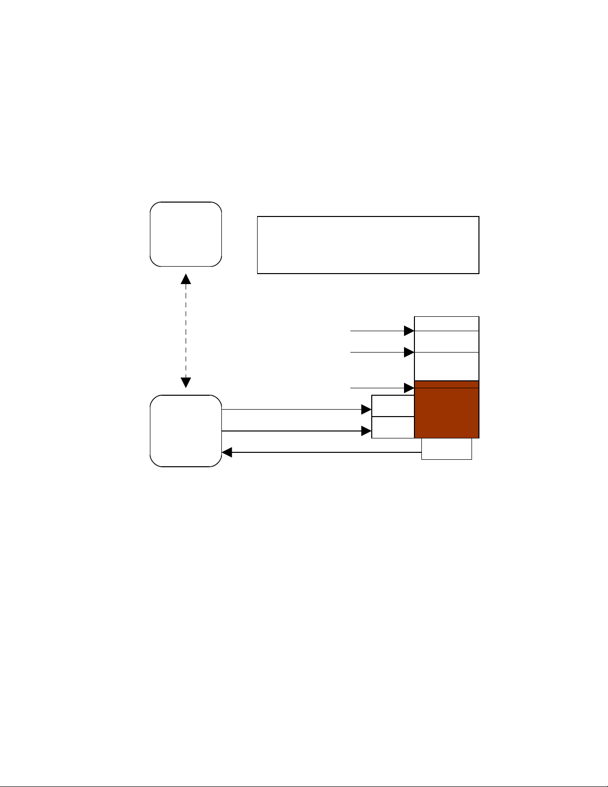
You can also use the ANALOG, IO, and/or CTRL commands, from your local terminal,
to carry out sensing and control functions at a local Kantronics TNC.
The following diagram illustrates the use of two Kantronics TNC/radio stations for
remote control and sensing. These operations could be carried out manually or via a
terminal program running in the computer in the central TNC station.
Remote Sensing and Control
Example: controlling the level of liquid in a tank
Central
Kantronics
TNC Based
Station
OPERATING RULES for controlling the level of the liquid:
1. If the level is "low" or less, turn the Pump ON.
2. If the level is "full" or more, turn the Pump OFF.
3. If the level is "too full" or more, OPEN the Drain.
4. If the level is "full" or less, CLOSE the Drain.
Tank
Remote
Kantronics
TNC Based
Station
radio
connection
between TNCs
Control line 1 (ON/OFF)
Control line 2 (OPEN/CLOSE)
A/D sensor line 1
Too Full
Full
Low
Pump
Drain
LIQUID
Pressure
As noted earlier, the Command Reference section and the ADVANCED
INSTALLATION section provide details needed to adapt these broad capacities to your
own situation, with your own sensors, controls, and remote locations.
71
Page 80

Command Reference
Introduction
This chapter documents all MT1200 commands.
There are many commands that affect operation of the MT1200. Some commands
affect performance under specific conditions, some change parameters affecting
general operation and others direct a one-time action.
The user changes parameters and issues instructions to the MT1200 by typing
commands composed of plain-text words or abbreviations, and variables which are
numbers or strings of characters chosen by the user, and then pressing ENTER. The
default settings of most commands will likely never need to be changed.
Default values are stored in the EPROM section of the MT1200 microprocessor. If you
change any setting or value, it will be stored automatically within a few seconds, and will
be the value used at future power-on.
Format Defining Commands
The Command Line
The first line of each command definition shows the syntax for entering the command,
beginning with the name of the command, followed by a listing of any parameters that
may be used with the command.
The full name of each command is shown in CAPS and a “short-form” of the command
is shown by the underlined characters in the name. The short-form of the command is
the shortest string of characters, starting from the beginning of the full name that will
allow the MT1200 to uniquely identify the command being requested.
The MT1200 scans an internal list of commands—which is NOT in alphabetical order—
and selects the first match with the string you enter.
The command name is followed by a space.
After the space, there may be one or more parameters that need to be used, or that
may optionally be used, with the command.
• Values that need to be entered as they are shown (or by using the short-form
indicated by the underlined character(s)) are shown in CAPS , as in “ON | OFF”.
72
Page 81

Parameter names for which a value needs to be substituted are shown in lower
case letters, as in “callsign,” which means a particular callsign needs to be
entered.
• Lists of parameter values are enclosed in curly brackets “{ }” for grouping clarity
and lists of optional parameter values are enclosed in square brackets “[ ]”.
• If more than one choice is possible for the value of a given parameter (i.e., flag),
choices are separated by a vertical bar, as in “ ON | OFF” or “OPTION1 |
OPTION2 | OPTION3".
• End your command entry with the ENTER key, which should send a <CTRL+M>.
If a parameter can take a range of values (or in cases such as ABAUD, any of a set of
numerical values) the parameter is shown as a name in lower case (e.g., “n”) and the
permissible range of values (or the list of possible values) is given in parentheses “( )” to
the right side of the command, after the syntax has been presented. For example,
possible values of the parameter “n” are defined as “(n = 1 - 255)”.
The Line Below the Command Definition
If commands have parameters, default values are shown on the line below the
command definition.
Some MT1200 commands take effect immediately, so they are called “immediate”
commands (e.g., K means “switch to CONVERSE mode"). This will be stated on the
second line. For example, the command to go to CONVERS mode says “immediate” on
the second line.
More Information on Commands
Each command is explained in detail and examples are given where appropriate.
Following the explanation of the command, there may be a “See also” list that shows
related commands.
Parameter Types
Almost all parameters are of one of the following types (exceptions are discussed when
they are encountered in the command listing).
n (range)
Any number within the range is permissible. The unit of measure (s, ms, baud, count,
etc.) for the number will be given in the description. These are decimal numbers.
73
Page 82

n ($00 - $FF)
Special functions: Some parameters are used to control special functions, such as
specifying the character to use to enter the Command mode from the Convers mode or
specifying the character to use for “backslash”. Possible values and default values for
these parameters are shown in HEX format.
The “digits” of a hex number represent powers of 16, analogous to the powers of 10
represented by a decimal number. The decimal numbers 10 through 15 are represented
in hex by the letters A through F (e.g., decimal 10 is hex A). And a hex number is
distinguished from a decimal number by preceding it with a “$” prefix.
For example:
$1B = (1*16) + 11 = 27
Number codes for these special characters are shown in hexadecimal (hex) form (i.e.,
base 16). They can be entered either in decimal or in hex. Permissible values are
shown in HEX: for example (n = $00 - $FF).
Note: Setting a function character to zero ($00) disables that function.
➔ See the ASCII Chart at end of this manual for a listing of ASCII codes for all
alphanumeric characters, including A to Z and 0 to 9, and conversions between hex and
decimal representations.
Several parameters are ASCII numerical values for characters, which perform special
functions. Most of these special function characters have “control characters” as default
values. Control characters are entered by holding down a special control key (normally
marked “Ctrl”) on the keyboard while typing the indicated key. For example, to enter a
<Ctrl+X>, hold down the Control key while typing an X, then release both keys.
These special characters cannot be sent in a packet unless preceded by the pass
character (see the PASS command) or unless you are operating in the Transparent
Mode.
If a special character is defined as “$” then you will need to enter values in decimal, or
precede the $ with the PASS character in order to enter hex numbers.
flags ChoiceA|ChoiceB
Many parameters are “flags”, meaning they have two possible values, ON and OFF, or
YES and NO. All of the command descriptions show ON and OFF as the options;
however YES (Y) and NO (N) may be typed instead. A few parameters are really flags,
but rather than indicating that something is “on” or “off”, they select one of two ways of
doing things. Some of these parameters have the values EVERY or AFTER indicating
operating modes for data transmission.
74
Page 83

The possible choices are separated by a vertical bar. Some of the flag parameters will
allow many choices, such as ON|OFF|TO|FROM.
callsigns xxxxxx-n
Several commands require callsigns as parameters. While these parameters are
normally Amateur callsigns, they may actually be any collection of numbers and/or
letters up to six characters; they are used to identify stations sending and receiving
packets. A callsign may additionally include an “extension” (SSID, Secondary Station
Identifier), which is a decimal number from 0 to 15 used to distinguish two or more
stations on the air with the same Amateur call (such as a base station and a repeater).
The callsign and extension are entered and displayed as call-ext, e.g. KBØNYK-3. If the
extension is not entered, it is set to -0, and extensions of -0 are not displayed by the
MT1200.
text
There are some commands, which have a parameter text string. This string can be any
combination of letters, numbers, punctuation, or spaces up to 128 characters.
In order to be used, all string parameters must contain at least one non-space
character. You can even put characters with special meanings, such as carriage return,
into the string by preceding them with the PASS character. The string ends when you
type a (non-passed) carriage return.
Entering Commands
To enter a command, the MT1200 needs to be in COMMAND Communication Mode (as
opposed to CONVERS or TRANS communication mode).
The prompt for Command Mode is:
cmd:
➔ Hint: Once you go into Packet Convers Mode a <Ctrl+C> (see COMMAND) needs to be
entered to return you to the Command Mode. In the Packet Transparent Mode or
MODEM Mode, a special sequence is needed to return to Command Mode (see
CMDTIME).
➔ Hint: If packets have been printing on the screen you may have forgotten which mode
you are in. If you wish to see the cmd: prompt type a <Ctrl+C>, to see if you are already
in Command Mode. If the prompt does not appear then you are either in Command
Mode or in Transparent Mode. If you are in Command Mode, typing a Return will
generate the “cmd:” prompt. If you are in Transparent Mode, you will not get the “cmd:”
prompt when you press the Return key; instead, you need to enter three <Ctrl+C>s in
rapid succession to switch to the Command Mode and get the “cmd:” prompt.
75
Page 84

When you are at the Command Mode prompt, you enter a command for the MT1200 by
typing the command name (in upper or lower case) and any required and optional
parameter values (argument settings or values).
The command name and each parameter value must be separated from each other by
at least one space.
To ENTER the command press the carriage return “CR” (usually an ENTER key). As
soon as the “CR” key is pressed, the MT1200 will process the command request and
take whatever action is specified (or inform you with an “EH?” if it does not understand
what you have entered).
As noted above, you can enter the short-form of a command name—the characters
underlined in the listing.
The short form is not necessarily the shortest unique string in the name or the first
match in alphabetical order—rather it is the first match that the MT1200 will find as it
scans through the non-alphabetical listing of commands in its BIOS.
➔ Hint: You can examine the value of any parameter by typing the command name
followed by a “CR”. A special command, DISPLAY, allows you to see the values of all
parameters or groups of related parameters.
76
Page 85

MT1200 Commands
All MT1200 commands are documented below, in alphabetical order. The underlined
characters in a command’s name show the short-cut version of the command. Required
or optional parameters are shown after the command name, as are allowable ranges of
values, where appropriate.
8BITCONV {ON | OFF}
default ON
This command was added to the first TNCs built (1980s) to accommodate terminals that
would not receive (or would be confused by) 8-bit characters, only 7-bit ASCII. We’ve
retained the command today just in case you’re using such a terminal or computer.
Also, it might be that your computer is capable of handling 8-bit characters but your
communications terminal program will reject (or be confused or “hung”) by them. In
these cases, you’ll need to set 8BITCONV OFF.
When ON, transmission of 8-bit data is allowed in the packet Convers Mode and
Transparent Mode. If you wish to obtain 8-bit data transmission but do not want all the
features of Transparent Mode, set this command to ON. If OFF, the 8th data bit is
stripped (set to 0) for transmission and all data received will have the 8th bit set to 0.
ABAUD n (n = 0,1200,2400,4800,9600,19200)
default 0
The parameter n sets the baud used for input and output through the serial RS232 port
of the MT1200 to the computer. If 0 is used, the MT1200 will run an autobaud routine
upon power-up. This routine looks for an asterisk (*) character from the attached
computer to set the ABAUD parameter.
If you wish to use a different baud, or to perform autobaud the next time the unit is
powered up, you must change the ABAUD parameter. If you change the baud in your
computer or terminal you should change the baud in the MT1200 first, then issue the
RESET command, then set the new baud on your computer. Otherwise a hard reset will
be required to erase the ABAUD setting and reinitialize the MT1200 to perform the
autobaud routine. (See Hard Reset section.) Note also that a hard reset will erase ALL
stored parameters in your MT1200 and return them to factory defaults.
See also: RESET, RESTORE
77
Page 86

ANALOG
immediate
Entering the ANALOG command returns a string of 2 values, based on the voltage
readings from A-to-D input lines, located on pins 7 and 9 of the Telemetry jack.
At any given time, each of the 2 A-to-D lines can have a voltage value somewhere in
the range of 0 – 3.3 V dc. Instead of reporting voltages, the ANALOG command returns
a decimal number as specified by the RANGE command. The defalut range selects
values of 0 – 255 (0 for 0volts input, to 255 for 3.3volts input) for each line. Each
decimal value corresponds to an input voltage.
The response is in the following form:
ANALOG AN0/AN1
AN0, input (0), reports a decimal number in the range of (0-255), representing the
•
current dc voltage of an external input read from pin 4 on the Radio Port.
AN1, input (1), reports a decimal number in the range of (0-255), representing the
•
current dc voltage of external input read from pin 8 on the Radio Port.
Data can be gathered from a remote site by connecting to MYREMOTE and then
issuing the ANALOG command.
See also: RANGE, TELEMETRY, MYREMOTE
AUTOLF {ON | OFF}
default ON
When ON, a line feed is sent to the terminal after each carriage return. This parameter
should be set on when overprinting occurs and the terminal being used does not
automatically supply its own linefeed after a carriage return. This command affects only
the data sent to the terminal, not data sent to the radio.
See also: CR, LFADD
78
Page 87

AX25L2V2 {ON | OFF}
default ON
This command provides compatibility with all known packet units implementing AX.25
protocol. When ON, Level 2 Version 2 protocol is implemented and the TNC will
automatically adapt to whichever version the connecting station is using. When OFF,
Level 2 Version 1 is implemented. Set this command to OFF if you need to digipeat
through other units, which do not digipeat version 2 packets. You may also find benefit
from setting this command OFF when using several digipeaters (not nodes) to send
packets, or when conditions are marginal between the two stations involved. (NOTE:
Changing this setting after connecting to another station will have no effect on the
current connection.)
The major difference in V1 and V2 protocol is the method used to handle retries. In the
connected mode, if a packet is sent and not acknowledged, Version 1 will re-send the
entire packet and then disconnect if the RETRY count is reached. Version 2 will first
send a poll, the response to this poll will determine if the packet was received. It is
possible that the ack was collided with and therefore the data packet does not need to
be resent. If the ACK shows that the data packet was not received, it will be retransmitted. Each time a poll is answered the TRIES count is reset to 0. If the RETRY
count is reached, version 2 will attempt to re-connect unless RELINK is OFF. If the reconnect attempt is unsuccessful, then version 2 will issue a disconnect.
See also: RELINK, RETRY, TRIES
For more information, see the book AX.25 Amateur Packet-Radio Link-Layer Protocol
Version 2.0 October 1984, which can be obtained from the ARRL.
AXDELAY n (n = 0 – 255)
default 0
The value of “n” is the number of 10 millisecond intervals to wait, in addition to
TXDELAY, after keying the transmitter before data is sent. This delay can be helpful
when operating packet through a standard “voice” repeater, or when using an external
linear amplifier which requires extra key-up time. Repeaters using slow mechanical
relays, split-sites, or both require some amount of time to get RF on the air.
See also: AXHANG
AXHANG n (n = 0 - 255)
default 0
79
Page 88

Each increment specifies 10 millisecond intervals. This value may be used to improve
channel utilization when audio repeaters with a hang time greater than 10 ms are used.
If the repeater squelch tail is long, it is not necessary to wait for AXDELAY after keying
the transmitter if the repeater is still transmitting. If the TNC has heard a packet within
the AXHANG period, it will not add AXDELAY to the key-up time.
See also: AXDELAY
BEACON [EVERY | AFTER] n (n = 0 - 255)
default Every 0
The value entered for “n” is the number of minutes (i.e., one-minute intervals) to use
with the beacon command.
A value of 0 turns the beacon OFF. Setting a value greater than 0 activates the beacon
under the conditions specified.
If the optional keyword Every is used, a beacon packet will be sent every n minutes. If
After is used, a beacon packet will be sent ONCE after the specified interval with no
channel activity.
The beacon frame consists of the text specified by BTEXT in a packet addressed to
“BEACON”. Beacon messages will be digipeated via any addresses specified in the
UNPROTO command.
See also: BTEXT, UNPROTO
BKONDEL {ON | OFF}
default ON
When ON, the sequence backspace-space-backspace is sent to the attached terminal
when the DELETE character is entered. When OFF, the backslash character “\\” is sent
to the terminal when the DELETE character is entered.
See also: DELETE, REDISPLAY
BREAK {ON | OFF}
default OFF
80
Page 89

If BREAK is ON, a modem break sent from the terminal causes a return to Command
Mode from Converse or Transparent Mode.
See also: COMMAND
BTEXT text (0 - 128 characters)
default (blank)
BTEXT specifies the content of the data portion of the beacon packet. Any combination
of characters and spaces may be used with a maximum length of 128.
Entering a single “%” will clear BTEXT.
See also: BEACON
BUDLIST [ON|OFF] [NONE | {+|-}call | call1,call2,...]
where call={callsign | {<|>}callsign | callsign{>|<>}callsign}
default OFF NONE
BUDLIST is used to determine which received packets will be monitored. When OFF or
NONE, BUDLIST will allow monitoring of all packets, even if it has callsigns in its list.
The maximum number of callsigns allowed in BUDLIST is 10. Up to 10 callsigns may be
entered at once, using the format shown after the command name, and the new list of
from 1 to 10 callsigns will replace whatever list was there before. The BUDLIST
command can be used to add a single callsign (+callsign), so long as there is room for
the new callsign on the list (if there is not, the TNC responds with “EH?” and returns you
to the command prompt). Similarly, you can remove a single callsign (-callsign) from the
list. And to remove all items from the current list, enter BUDLIST NONE.
A callsign entered without a SSID will match any SSID of that callsign. To match a
specific SSID only, enter the callsign with that SSID: for example, callsign-n, where n =
0-15.
More selective monitoring is enabled when a callsign or two callsigns is combined with a
“>” and/or a “<” character. For example, entering “>callsign” will enable monitoring of
packets TO that callsign (assuming BUDLIST is ON), entering “<callsign” will enable
monitoring of packets from the callsign, entering “callsign1>callsign2" will enable
monitoring of packets from callsign1 to callsign2, and entering ”callsign1<>callsign2" will
enable monitoring of packets from callsign1 to callsign2 and vice versa.
81
Page 90

➔ Note that entering callsign1>callsign2 or callsign1<>callsign2 counts as two of the 10
maximum allowed callsigns.
CALIBRAT
immediate
The CALIBRATE command can be used to generate a signal which may be used as an
aid in adjusting transmit audio drive level to your transceiver, or can be used to
detemine whether an equalization adjustment is required.
The use of this command is explained in the Calibration/Equalization Section.
See also: XMITLVL, Calibration/Equalization section
CANLINE n (n = $00 - $FF)
default $18 <Ctrl+X>
This command is used to change the cancel-line input editing command character.
When in Convers or Command Mode entering a <Ctrl+X> will cancel all characters input
from the keyboard back to the last un-PASSed carriage return (unless PACTIME has
expired, CPACTIME is turned on, and you are in Convers Mode).
See also: CANPAC, CPACTIME, PASS
CANPAC n (n = $00 - $FF)
default $19 <Ctrl+Y>
This command is used to change the cancel-packet command character. When in the
Convers Mode entering a <Ctrl+Y> will cancel all keyboard input back to the last
unpassed SENDPAC character (unless PACTIME has expired and CPACTIME is
turned on).
This character also functions as a cancel-output character in Command Mode. Typing
the cancel-output character a second time re-enables normal output. For example, if
you’ve told the TNC to do a DISPLAY, a <Ctrl+Y> will cancel the display and a second
one re-enables the cmd: prompt after the next “CR”.
See also: CANLINE, CPACTIME, SENDPAC
82
Page 91

CD {INTERNAL | EXTERNAL | SOFTWARE}
default INTERNAL
The CD command selects which carrier detect method will be used.
When set to INTERNAL, the TNC will detect a signal present on the channel, using an
energy type carrier detect, allowing shared voice and data on the same channel. Any
receive audio will trigger carrier detect.
When set to EXTERNAL, a signal is supplied by an external device, through the XCD
pin on the radio port, to indicate that a receive signal is present.
If set to SOFTWARE, the firmware inside the TNC will detect the presence of received
packet data to enable the carrier detection, allowing operation with un-squelched audio.
Correct operation of SOFTWARE carrier detect is affected by proper equalization and
the SWP parameter. If your RCV light flickers while receiving a packet, this is an
indication that you may need to adjust the equalization. (Equalization is set with an
internal jumper.)
When CD is set to INTERNAL or SOFTWARE, the external carrier detect pin on the
radio connector (if wired) can be used to hold off the TNC from keying the radio.
See also: SWP
CDINVERT {ON | OFF}
default OFF
Sets the sense of the XCD input. When set to OFF, a low input (near ground) is
expected to indicate a busy channel. When set to ON, expects a high (above 2 volts) to
indicate a busy channel.
CHECK n (n = 0 - 255)
default 0
The value entered for “n” is the number of 10 second intervals to wait during “no activity”
before making a periodic check (poll) to determine that a connected state still exists.
This “timeout” command is used to prevent a “hang-up” in a connected mode when a
link failure occurs as a result of conditions beyond control of the connected stations.
If n equals 0, this “timeout” function is disabled. While using Version 1 (AX25L2V2
OFF), a check timeout will initiate a disconnect.
83
Page 92

See also: AX25L2V2, RELINK, RNRTIME
CHFREE [EVERY] [[hh:]mm:]ss START [[hh:]mm:]ss [FOR [[hh:]mm:]ss]
default Every 00:00:00
When a time is entered, defines a “window” of time when any transmissions are
allowed.
The START option sets a time to begin the “window”, and the FOR option sets a
duration after START to leave the “window” open.
Outside of the specified “window” of time, no transmissions are allowed.
CMDTIME n (n = 0 - 15)
default 1
This command sets the time allowed for entry of required characters to exit the
Transparent Mode (or LINESUB, MODEM, or TUP modes). In order to allow exit to
Command Mode from Transparent Mode, while permitting any character to be sent as
data, a guard time of CMDTIME seconds is set up.
Entering a value for “n” sets the value of CMDTIME to “n seconds”.
To exit Transparent mode, you need to wait at least CMDTIME since the last data
character was sent to the MT1200. Then you need to enter the COMMAND character
(e.g., <Ctrl+C>)) three times, with a wait of LESS THAN the value of CMDTIME
between the first and second time you enter the COMMAND character and also a wait
of LESS THAN the value of CMDTIME between the second and third time you enter the
COMMAND character.
After a final delay of CMDTIME the TNC will exit Transparent Mode and enter
Command Mode. At this time you should see the cmd: prompt. If CMDTIME is set to
zero, the only exit from Transparent Mode is a modem break signal, assuming BREAK
is set to ON.
For example (if CMDTIME is 1 second and COMMAND is <Ctrl+C>): wait one second,
type a <Ctrl+C>, within one second type a second <Ctrl+C>, within one second type a
third <Ctrl+C>, WAIT one second, cmd: prompt should appear. If your
computer/program has the capability you can also send a modem break to escape
Transparent Mode.
See also: COMMAND, TRANS, BREAK
84
Page 93

CMSG {ON | OFF | DISC}
default OFF
When OFF, the custom connect text stored in CTEXT will not be sent to the connecting
station upon receiving a connect request. When ON, the custom CTEXT string will be
sent. When CMSG is set to DISC, the custom CTEXT string will be sent to the
connecting station, and then your TNC will disconnect from that station.
See also: CTEXT
COMMAND n (n = $00 - $FF)
default $03 <Ctrl+C>
This command is used to change the Command Mode entry character. When
COMMAND is set to the default value, typing a <Ctrl+C> causes the TNC to return to
Command Mode from packet Convers Mode. See CMDTIME for returning to Command
Mode from Transparent Mode.
CONLIST [ON | OFF] [NONE | {+|-}callsign | callsign1,callsign2...]
default OFF
CONLIST is used to determine which stations (callsigns) may use your station for ANY
purpose, including digipeating.. When ON, the TNC will recognize only those packets
received with a callsign that appears in the CONLIST’s list of callsigns; and you will not
be able to connect to any station that is not in the conlist. When OFF, the TNC will
process all packets.
The maximum number of callsigns allowed in CONLIST is 10. Up to 10 callsigns may be
entered at once, using the format shown after the command name, and the new list of
from 1 to 10 callsigns will replace whatever list was there before. The CONLIST
command can be used to add a single callsign (+callsign), so long as there is room for
the new callsign on the list (if there is not, the TNC responds with “EH?” and returns you
to the command prompt). Similarly, you can remove a single callsign (-callsign) from the
list. And to remove all items from the current list, enter CONLIST NONE.
A callsign entered without a SSID will match any SSID of that callsign. To match a
specific SSID only, enter the callsign with that SSID: for example, callsign-n, where n =
0-15.
85
Page 94

CONMODE {CONVERS | TRANS}
default CONVERS
This command controls the mode the TNC will be placed in AUTOMATICALLY after a
connect if NOMODE is OFF. The connect may result either from a connect request
received or a connect request originated by a CONNECT command. If the TNC is
already in Convers or Transparent Mode when the connection is completed, the mode
will not be changed. If you have typed part of a command line when the connection is
completed, the mode change will not take place until you complete the command or
cancel the line input.
See also: CANLINE, CONNECT, CONVERS, NOMODE, TRANS
CONNECT call1 [VIA call2,call3,...,call9]
immediate
call1 = callsign of station to be connected to.
call2,...,call9 = optional stations to be digipeated through. A maximum of 8 digipeater
addresses (callsigns or aliases) can be specified. This is referred to as a path.
Each callsign may also have an optional Secondary Station Identifier (SSID) specified
as -n, where n = 1 - 15. The digipeat callsigns are specified in the order in which they
are to relay transmitted packets. The mode set by CONMODE will be entered upon
successful connect, if NOMODE is OFF. If no response to the Connect request occurs
after RETRY attempts, the command is aborted. A timeout message is printed on the
display and the TNC remains in the Command Mode. The station being connected to
(call1) may receive the connect request but be unable to accept connects, in which case
a busy message will be printed to the screen and the TNC will stay in Command Mode.
Connect requests may only be initiated in the Command mode.
If a connect is in progress, or already established, the path may be changed by simply
re-issuing the CONNECT command with the desired path. This must be done in
command mode.
CAUTION, packets en route between your station and the reconnected station may be
lost.
If CONNECT is entered with no parameters, the current connect status is displayed.
See also: CONMODE, CONOK, DBLDISC, NOMODE, RETRY, RING, XMITOK
86
Page 95

CONOK {ON | OFF}
default ON
When ON, connect requests from other TNCs will be automatically acknowledged and a
<UA> packet will be sent. The standard connect message will be output to the terminal
and the mode specified by CONMODE will be entered if you are not connected to
another station and NOMODE is OFF.
When OFF, connect requests from other TNCs will not be acknowledged and a <DM>
packet will be sent to the requesting station. The message “connect request: (callsign of
whoever is trying to connect to you)” will be output to your terminal if INTFACE is
TERMINAL or NEWUSER.
See also: CONMODE, CONNECT, INTFACE, MONITOR, NOMODE
CONVERS
immediate
CONVERS has no options. It is an immediate command and will cause entry into
Conversational Mode from Command Mode. Any link connections are not affected.
➔ Hint: K is the same as CONVERS, for quicker entry.
See also: K, COMMAND
CPACTIME {ON | OFF}
default OFF
When OFF and in the Convers Mode, packets are sent when the SENDPAC character
is entered or when PACLEN is achieved. When ON and in the Convers Mode, packets
are sent at periodic intervals determined by PACTIME. Characters are sent periodically
as in Transparent Mode but the local editing and echoing features of Convers Mode are
enabled.
See also: CONVERS, CR, PACLEN, PACTIME, SENDPAC, TRANS
CR {ON | OFF}
default ON
87
Page 96

When ON the SENDPAC character (normally carriage return) is appended to all packets
sent in Convers Mode except when PACLEN is exceeded. Setting CR ON and
SENDPAC $0D results in a natural conversation mode. Each line is sent when a “CR” is
entered and arrives at its destination with the “CR” appended to the end of the line. To
avoid overprinting, AUTOLF may need to be ON at the receiving end.
See also: AUTOLF, LFADD, SENDPAC
CRSUP {ON | OFF}
default OFF
This command was added to the first multi-mode TNCs (such as the Kantronics UTU
and KAM) to accommodate the practice by radio teletype (RTTY) operators of adding
an extra carriage return (CR) at the end of each line (i.e., CR, CR, linefeed (LF) ). This
was done to give the carriage of the old mechanical teletypes time to return across the
page. Some of these machines are still in use, so we’ve retained this command so you
can “correct” the data you might receive from such a station. To do so, turn CRSUP ON.
When ON, this command suppresses every other carriage return (when no data is
between them) in the received data before sending the data to the terminal. When
CRSUP is OFF, all carriage return characters are left in the received data as it is sent to
the terminal.
See also: AUTOLF, LFSUP
CSTAMP {ON | OFF}
default OFF
When ON, the daytime stamp is printed with all “*** CONNECTED TO” and “***
DISCONNECTED” messages on the terminal.
See also: CONNECT, DAYTIME, DISCONNECT, MSTAMP
CTEXT text (0 - 128 characters)
default (blank)
Enter any combination of characters and spaces up to maximum length of 128. Entering
a single ‘%’ will clear CTEXT. This entry specifies the text of the first packet to be sent
in response to an accepted connect request provided that the parameter CMSG is not
OFF.
88
Page 97

See also: CMSG, CONNECT
CTRL {A | B} { OFF | ON | LONG | n} (n=1-20)
immediate
This command causes the MT1200 to activate (or deactivate) the specified output line
(A or B) to the radio port as indicated. If A or B output is not specified, both outputs are
affected. For instance, to pulse the A output (CTLA on the schematic) 3 times, you
would give the command “CTRL A 3". You may optionally specify the number of times
to pulse the output (n), or to turn the output ON, or OFF. Each pulse on the output line
lasts approximately 100 ms (0.1 s). Specifying LONG results in one pulse of the output
line, lasting approximately 1.5 s. These output lines are open drain outputs and are
pulled to ground when active. For more information, see the section on “Connecting to
your Radio” in this manual.
Do not allow more than 200 mA of current in this circuit.
CWID [{EVERY | AFTER}] n (n = 0 - 255)
default EVERY 0
Each increment specifies 1-minute intervals. A value of 0 turns the ID OFF. Setting a
value greater than 0 activates the ID under the conditions specified. If the optional
keyword “Every” is used, an ID will be sent every n minutes. If set to “After”, an ID will
be sent ONCE after the specified interval with no channel activity.
The string specified by the CWIDTEXT command will be sent in Morse Code, using
AFSK tones.
Some countries require all stations to ID in Morse code periodically.
See also: MYCALLl, CWIDTEXT
CWIDTEXT text (0-15 characters)
default DE mycall
This command sets the text to be transmitted when the MT1200 performs an automatic
CWID. The text will be transmitted periodically as set by the CWID command.
See also: CWID
89
Page 98

DAYSTR text
default yyyy-mm-dd hh:mm:ss
The DAYSTR command is used to set the FORMAT of your date/time display. DO NOT
enter an actual date or time, simply enter the form of the display you would like, using
the lower case letters m, d, h, y, and s as described below.
The format you enter is used for displayed time stamps.
The lower case characters m, d, y, h, and s have special meaning to this command and
will be replaced with data from the software clock. The lower case m will be replaced
with the minutes the first time it appears after a lower case h. If h, m, y, d, or s is
specified as a single character, the corresponding date/time element will be displayed
as a single digit if the value is less than 10. Entering two characters will force a two digit
display for values under 10. If the month is entered as three ms, it will be displayed as
the first three characters of the month name (JUL). You may also enter any other text
you wish, allowing you to add such things as your time zone.
➔ Remember ALL lower case m, d, y, h, and s will be replaced by actual values.
Some examples of setting the DAYSTR command and the resulting time/date display
are:
DAYSTR setting Displayed Date/Time
mm/dd/yy hh:mm:ss 07/16/02 12:14:22
d.m.y h:mm:ss 16.7.02 12:14:22
d.mm.yy h:mm 16.07.02 12:14
mmm d 20yy h:mm CST JUL 7 2002 12:14 CST
TIME hh:mm DATE: mmm dd, 20yy TIME 12:14 DATE JUL 07, 2002
➔ The DAYSTR command is used to define how date and time are to be displayed; it is
not used to enter an actual date and time (which you do by using DAYTIME). If you
enter an actual date and time with the DAYSTR command, your clock will appear to
stop.
See also: DAYTIME
DAYTIME yyyy-mm-dd hh:mm:[ss]
DAYTIME is used to enter a date and time (after which time and date are formatted for
display by the specifications given in DAYSTR).
When date and time are entered, using the input format specified in the command and
explained below, the values entered are used to set the software clock/calendar. The
software clock/calendar is then used for MHEARD logging, as well as for CSTAMP and
MSTAMP functions.
90
Page 99

When entering the daytime digits, enter them in the specified default sequence. Notice
that there are four digits for the year, then two digits each for month, day, hours,
minutes, and (optionally) seconds. Also, notice that you need to use the order given
here, which has nothing to do with the format (given in DATSTR) for displaying date and
time values. For example, to enter 2006, December 1, at 14:30:00 hours, the value of
the DAYTIME parameter would be 2006-12-01 14:30:00
If DAYTIME is entered with no parameter, the daytime is displayed using the format
defined by the DAYSTR command.
➔ Hint: If the time appears to be stuck, check the current value of DAYSTR, to be sure
that the DAYSTR setting is being used to format the display of time and date, and not
(in error) to attempt to supply an actual date and time. If this is not the case, fix the
problem and see if time and date displays work correctly.
If the MT1200 was ordered with the internal GPS installed, the Daytime will
automatically be set based on GPS time, upon valid GPS fix.
See also: CSTAMP, DAYTWEAK, DAYSTR, MHEARD, MSTAMP
DAYTWEAK n (n = 0 - 15)
default 8
This parameter is used to adjust the software clock, if needed, for accurate time
keeping. Increasing the parameter will slow the clock, decreasing the parameter will
speed up the clock. Each count corresponds to 0.64 s increase or decrease per 24 h.
Ambient temperature will affect the clock to some degree.
The software clock stops when a soft reset or powering off occurs, and upon power on
the software clock restarts.
DAYZONE n (n = -12 to +12)
default 0
This parameter is used to adjust the display of time, in relation to GPS time. If your
displayed time is UTC, there will be a difference from GPS time. Enter the difference to
correct the UTC display.
DBLDISC {ON | OFF}
default OFF
91
Page 100

When OFF, only one disconnect command (D) need be given to terminate an
unsuccessful connect attempt. If you are actually connected, the normal disconnect
sequence will occur.
When ON, a normal disconnect sequence will always occur (you will not be
disconnected until you receive an acknowledge of your disconnect or until the retry
count is exceeded). A second D is required to force a local disconnect independent of
the retry counter.
See also: DISCONNECT
DELETE n (n = $00 - $FF)
default $08 <Ctrl+H>
This command sets the character to be used as the delete character. When this
character is typed, the last input character is deleted. The most common settings are
$08 (backspace) and $7F (delete).
See also: BKONDEL
DIGIPEAT {ON | OFF | UIONLY}
default ON
When ON, any packet received that has MYCALL, or MYALIAS, in the digipeat list of its
address field will be retransmitted. Each station included in the digipeat list relays the
packet in the order specified in the address field. Digipeating takes place concurrently
with other TNC operations and does not interfere with normal connected operation of
the station. To disable digipeat operations (via MYCALL, or MYALIAS), set this
command to OFF.
If UIONLY is selected, the MT1200 will digipeat UI frames only. Connect type packets
will be ignored.
See also: HID, MYALIAS, MYCALL
DISCONNE [MYREM ]
immediate
When given without options, “disconnect” will initiate an immediate disconnect request.
A successful disconnect results in the display of “*** DISCONNECTED”. If the RETRY
92
 Loading...