

Page 1

1
KANTRONICS
KAM XL
Reference Manual
Page 2

2
Table of Contents
Table of Contents .................................................................................................................................................................... 2
Contact Us: .............................................................................................................................................................................. 5
REVISIONS ............................................................................................................................................................................ 6
Disclaimer Notice .................................................................................................................................................................... 6
Kantronics Warranty Registration ........................................................................................................................................... 7
IMPORTANT .......................................................................................................................................................................... 8
License Agreement .................................................................................................................................................................. 8
LIMITED WARRANTY ........................................................................................................................................................ 9
Return/Repair Procedures ...................................................................................................................................................... 11
Radio Frequency Interference Statement .............................................................................................................................. 13
RFI Suppression ................................................................................................................................................................ 13
FCC Declaration of Conformity: ........................................................................................................................................... 14
CE Marking Considerations .................................................................................................................................................. 14
Introduction ........................................................................................................................................................................... 15
KAM XL features: ............................................................................................................................................................. 15
GPS compatibility: ............................................................................................................................................................ 15
APRS digipeater: ............................................................................................................................................................... 15
Large PBBS: ...................................................................................................................................................................... 15
E-mail: ................................................................................................ ................................................................ ............... 16
Control and Sensing: ......................................................................................................................................................... 16
Remote access: .................................................................................................................................................................. 16
Other operations: ............................................................................................................................................................... 16
Software control: ............................................................................................................................................................... 16
Configurations: .................................................................................................................................................................. 16
Installation ............................................................................................................................................................................. 17
Package Contents .............................................................................................................................................................. 17
Additional Parts Required for a Multi-Mode Radio Station .............................................................................................. 18
Front panel of the KAM XL ............................................................................................................................................... 18
Rear panel of the KAM XL ................................................................................................................................................ 18
CONNECTING THE KAM XL TO A POWER SOURCE ............................................................................................... 19
CONNECTING THE KAM XL TO A COMPUTER ........................................................................................................ 19
The Terminal Program ...................................................................................................................................................... 23
CONNECTING THE KAM XL TO TRANSCEIVERS.................................................................................................... 24
AUX PORT (RS232 – DTE) ............................................................................................................................................. 26
CONNECTING A GPS DEVICE ..................................................................................................................................... 26
Interface Communication modes of the KAM XL ................................................................................................................. 27
Terminal Mode .................................................................................................................................................................. 27
Kantronics Host Mode ....................................................................................................................................................... 27
KISS Mode ........................................................................................................................................................................ 28
XKISS (Extended KISS) Mode ......................................................................................................................................... 29
COMMUNICATION MODES IN THE KAM XL ............................................................................................................... 30
Packet Mode ...................................................................................................................................................................... 30
AX.25 Protocol for Amateur Packet Radio: ...................................................................................................................... 30
Remote Access .................................................................................................................................................................. 36
Other Packet Modes of Operation ......................................................................................................................................... 37
PBBS (Personal Mailbox) ................................................................................................................................................. 37
PBBS Commands .............................................................................................................................................................. 39
Advanced PBBS Configuration ......................................................................................................................................... 45
Remote SYSOP Access to the PBBS ................................................................................................................................ 46
KA-NODE ............................................................................................................................................................................. 47
Overview ........................................................................................................................................................................... 47
Configuring The KA-Node ................................................................................................................................................ 47
Using a KA-Node .............................................................................................................................................................. 48
Using the XCONNECT Command ................................................................................................................................... 48
Remote Commands of the KA-Node ................................................................................................................................. 49
K-NET ................................................................................................................................................................................... 51
K-Net Configuration .......................................................................................................................................................... 51
Page 3

3
Networking terms .............................................................................................................................................................. 52
K-Net SYSOP Commands ................................................................................................................................................ 53
K-Net USER commands: .................................................................................................................................................. 57
GPS NMEA, Weather station Interfacing ............................................................................................................................. 60
Overview ........................................................................................................................................................................... 60
GPS Equipment Requirements .......................................................................................................................................... 60
Cabling a GPS Unit to the KAM-XL ................................................................................................................................. 61
Configuring the GPS Commands ...................................................................................................................................... 61
Other GPS Features ........................................................................................................................................................... 62
GPS Command Summary.................................................................................................................................................. 64
Advanced GPS/APRS Digipeating .................................................................................................................................... 65
Improving Efficiencies of Advanced Digipeating ............................................................................................................. 65
Overview of UI Digipeating Commands ........................................................................................................................... 65
Configuring Digis for HF/VHF Gateway Operations........................................................................................................ 66
OTHER FUNCTIONS .......................................................................................................................................................... 68
TELEMETRY ................................................................................................................................................................... 68
Copying NWS EMWIN Weather Broadcasts .................................................................................................................... 68
DAMA ............................................................................................................................................................................... 69
HF Modes (Non-Packet) ....................................................................................................................................................... 71
Tuning in to receive signals ............................................................................................................................................... 71
Exiting non-packet modes ................................................................................................................................................. 71
CW ........................................................................................................................................................................................ 71
Receiving CW ................................................................................................................................................................... 71
Tuning in CW a signal ....................................................................................................................................................... 71
Transmitting CW ............................................................................................................................................................... 72
CW Directives ................................................................................................................................................................... 73
RTTY .................................................................................................................................................................................... 74
Receiving RTTY ............................................................................................................................................................... 74
Tuning RTTY signals ........................................................................................................................................................ 74
Transmitting RTTY ........................................................................................................................................................... 74
RTTY Directives ............................................................................................................................................................... 74
MARS Feature ................................................................................................................................................................... 75
ASCII .................................................................................................................................................................................... 77
Receiving ASCII ............................................................................................................................................................... 77
Tuning ASCII signals ........................................................................................................................................................ 77
Transmitting ASCII ........................................................................................................................................................... 77
ASCII Directives ............................................................................................................................................................... 77
AMTOR (includes LAMTOR, FEC, SELFEC, NAVTEX) .................................................................................................. 79
AMTOR Operation ............................................................................................................................................................ 79
Calling CQ ......................................................................................................................................................................... 79
Answering a CQ ................................................................................................................................................................ 80
Mode B (FEC) Operation .................................................................................................................................................. 81
Mode B (SELFEC) Operation ............................................................................................................................................... 81
Receiving Mode B SELFEC ............................................................................................................................................. 81
Transmitting Mode B SELFEC ......................................................................................................................................... 81
LAMTOR (Listen Amtor) operation ..................................................................................................................................... 81
Notes on AMTOR operation ............................................................................................................................................. 82
AMTOR directives ............................................................................................................................................................ 82
NAVTEX .............................................................................................................................................................................. 83
NAVTEX/AMTEX Theory ............................................................................................................................................... 83
NAVTEX/AMTEX Operation .......................................................................................................................................... 84
NAVTEX directives .......................................................................................................................................................... 85
PACTOR (PTL, PTFEC) ...................................................................................................................................................... 86
Pactor Operation ................................................................................................................................................................ 86
Tuning Pactor signals ........................................................................................................................................................ 86
Monitoring Pactor FEC ..................................................................................................................................................... 86
Calling CQ or Transmitting FEC....................................................................................................................................... 86
Linking to another station .................................................................................................................................................. 86
PTLISTEN Mode .............................................................................................................................................................. 87
G-TOR (and GMON) ............................................................................................................................................................ 88
Page 4

4
G-TOR Operation ................................................................................................................................ .............................. 88
Tuning G-TOR .................................................................................................................................................................. 89
Monitoring G-TOR ............................................................................................................................................................ 89
Linking to another station in G-TOR ................................................................................................................................ 89
Speed changes ................................................................................................................................................................... 89
PBBS Access in G-TOR .................................................................................................................................................... 90
Summary of GTOR Directives .......................................................................................................................................... 91
PSK31 ................................................................................................................................................................................... 93
Tuning PSK31 Signals ...................................................................................................................................................... 93
Transmitting PSK31 .......................................................................................................................................................... 93
Exiting PSK mode ............................................................................................................................................................. 93
PSK31 Directives .............................................................................................................................................................. 93
Command Reference ............................................................................................................................................................. 95
Introduction ....................................................................................................................................................................... 95
Entering Commands .......................................................................................................................................................... 98
COMMANDS ....................................................................................................................................................................... 99
Appendix A: Installation ..................................................................................................................................................... 181
Precautions ...................................................................................................................................................................... 181
Connecting to Radios ...................................................................................................................................................... 181
Interfacing Hand-Held Radios ................................................................ ................................................................ ......... 182
Port 1: HF and Packet ...................................................................................................................................................... 183
Transmit level .................................................................................................................................................................. 184
Appendix B: Advanced Information ................................................................................................................................... 185
Disassembly and Assembly ............................................................................................................................................. 185
Hard Reset ....................................................................................................................................................................... 185
Updating/Uploading new BIOS (Firmware) ................................................................................................................... 186
Calibration ....................................................................................................................................................................... 187
PTT (Push-to-Talk) Watchdog Timer ............................................................................................................................. 189
Jumpers............................................................................................................................................................................ 190
Appendix C: Replacing the Lithium Battery ....................................................................................................................... 192
Appendix D: In Case of Difficulty ...................................................................................................................................... 193
Appendix E: Additional Information ................................................................................................................................... 195
Messages from the KAM XL ........................................................................................................................................... 195
Page 5

5
Contact Us:
Kantronics
14830 W. 117th St.
Olathe, Kansas 66062
Orders/Inquiries (913) 839-1470
FAX (913) 839-8231
E-mail sales@kantronics.com
Website: www.kantronics.com
Service/Technical Support (913) 839-8143 (8 AM to 12PM and 1 to 5 PM Central
Time, M-F)
FAX (913) 839-8231
E-mail service@kantronics.com
Page 6

6
REVISIONS
Revision
Date
Description
B
2006-5-18
Updated Kantronics address
C
2006-08-22
CE mark removed pending RoHS compliance.
D
2011-07-31
Updated contact information, text revisions, formatting.
E
2015-05-28
Updated to a searchable format.
The Kam XL is a Kantronics hardware and software design incorporating the AX.25 Level 2 Version 2
Packet protocol as adopted by the American Radio Relay League.
We have attempted to make this manual technically and typographically correct as of the date of the
current printing. Production changes to the TNC may add errata or addendum sheets. Your
comments and/or suggested corrections can be sent to us (see our contact information).
This document was compiled in the U.S.A.
The Kam XL is manufactured in the U.S.A.
© Copyright 2000-2015 by Kantronics. All Rights Reserved.
Contents of this publication or the firmware within the Kam XL may not be reproduced in any form
without the written permission of the copyright owner.
KAM XL, Pacterm, K-Net, and G-Tor are registered trademarks of Kantronics Co., Inc.
KPC-3 Plus is a registered trademark of Kantronics Co., Inc.
KPC-9612 Plus is a registered trademark of Kantronics Co., Inc.
NET/ROM is a registered trademark of SOFTWARE 2000.
APRS is a registered trademark of Bob Bruninga, WB4APR.
HyperTerminal is a registered trademark of Microsoft.
PSK31 is a design of Peter Martinez, G3PLX.
Special Thanks to Peter for his consultation and direction of implementation of PSK31 in the Kam XL.
Disclaimer Notice
We have attempted to make this manual technically and typographically correct as of the date of the
current printing. Production changes to the KAM XL may add changes to the manual at a later date.
Information in this document is subject to change without notice.
Contents of this publication or the firmware within the KAM XL may not be reproduced in any form
without the written permission of the copyright owner.
Your comments and suggestions are welcome, see our Contact Us information.
Printed in the United States of America.
Page 7

7
Kantronics Warranty Registration
Please take the time to (print this page) fill out the warranty registration form and mail it to
Kantronics, including a copy of your sales receipt, to register your purchase. Refer to the warranty
policy in this manual for further information.
Mail form and sales receipt to:
Kantronics
14830 W 117th Street
Olathe, KS 66062
Warranty Registration
Last Name: First Name:
Call Sign: .
Mailing Address:
City:
State: Zip/Postal Code: Country:
Telephone: E-Mail:
Product: KAM XL Serial #:
Date of Purchase: Dealer:
Page 8

8
IMPORTANT
READ THIS PAGE BEFORE INSTALLING THIS KANTRONICS PRODUCT
This product contains SOFTWARE on Programmable Memory (ROM) and/or diskette, which is
protected by both United States copyright law and international treaty provisions.
If you install or use this product, you will be deemed to be bound by the terms of the SOFTWARE
license shown below. If you do not wish to be bound by such license, return the (unused) complete
product package to your supplier for refund. The supplier may deduct restocking/re-packaging costs.
License Agreement
1. License. In consideration of payment of the License Fee, which is included in the price of the product, the Licensee
(you) is granted by the Licensor (Kantronics Company, Inc. - Kantronics) a non-exclusive right to use the
SOFTWARE and associated documentation. No ownership rights to the SOFTWARE or its Documentation are
transferred from Kantronics to you.
2. Term. This License Agreement is effective until terminated. You may terminate this Agreement by destroying the
PROM or diskette or CD and documentation. You may not rent or lease the SOFTWARE, but you may transfer the
SOFTWARE and accompanying written materials on a permanent basis provided you retain no copies and the
recipient agrees to the terms of this Agreement. Kantronics may terminate this Agreement without notice if you violate
any terms or conditions of the Agreement. In the event of termination of the Agreement, provisions relating to
Kantronics’ disclaimers of warranties, limitation of liability, remedies, or damages and Kantronics’ proprietary rights
shall survive.
3. Object Code. The SOFTWARE is delivered in object code only. You shall not reverse compile or otherwise reverse
engineer the SOFTWARE.
4. Limited Warranty. This product is covered by the standard Kantronics Limited Warranty, which is enclosed.
5. General. This License Agreement constitutes the complete Agreement between you and Kantronics.
The SOFTWARE and/or Documentation may not be exported or re-exported in violation of any export laws or regulations
of the United States of America or any other applicable jurisdiction.
This Agreement shall be governed by and interpreted under the laws of the State of Kansas, United States of America.
Use, duplication, or disclosure by the Government of the United States is subject to restrictions as set forth in subparagraph
(c)(1)(ii) of the Rights in Technical Data and Computer SOFTWARE clause of DFARS 252.227-7013.
Kantronics may in its sole discretion, provide you with upgrades of the SOFTWARE and/or Documentation if you have
provided Kantronics your completed Warranty registration with a copy of your receipt showing the amount you paid.
LICENSEE ACKNOWLEDGES HAVING READ AND UNDERSTOOD THIS AGREEMENT AND AGREES TO BE
BOUND BY ITS TERMS. LICENSEE FURTHER AGREES THAT THIS AGREEMENT IS THE COMPLETE AND
EXCLUSIVE STATEMENT OF THE AGREEMENT BETWEEN LICENSEE AND LICENSOR AND SUPERSEDES
ANY PROPOSAL OR PRIOR AGREEMENT, ORAL OR WRITTEN, AND ANY OTHER COMMUNICATIONS
RELATING TO THE SUBJECT MATTER OF THIS AGREEMENT.
Any questions concerning this Agreement or any other matter relating to Kantronics, Kantronics products, or business
practices, may be sent to us by any of the means on our contact information page.
Page 9

9
LIMITED WARRANTY
KANTRONICS CO., INC.
LIMITED WARRANTY
Effective January 1, 1997
To receive notice of future updates, new product information and prompt warranty service, please fill in the
Kantronics Warranty Registration form COMPLETELY and return it along with a copy of proof of purchase (to
establish purchase date) by any means to us (see our Contact Us page).Warranty Registration form and proof of
purchase may be e-mailed to sales@kantronics.com.
NOTE: Return of the Warranty Registration form and proof of purchase is a pre-condition to warranty
coverage.
1. WARRANTY. Kantronics warrants to the first consumer purchaser (“you”), for the Applicable
Warranty Period (as described below), that the Applicable Product (as described below) will be free
from defects in material and workmanship.
2. REMEDY. Kantronics agrees that, for any Applicable Product found by Kantronics to be in
violation of the warranty of Section 1 hereof within the Applicable Warranty Period, it will, at its
option, repair or replace the defective Applicable Product at no charge to you, excluding in-bound
shipping charges.
3. EXCLUSIVE REMEDY. Repair or replacement of the Applicable Product, as provided herein, is
the sole remedy available to you against Kantronics, and in no event will Kantronics be responsible
for any other liability or damages or for incidental, special, or consequential damages, regardless of
whether purported liability is predicated upon negligence, strict tort, contract, or other products
liability theory and whether or not Kantronics is warned about the possibility of such liability or
damages. SOME STATES DO NOT ALLOW THE EXCLUSION OR LIMITATION OF
INCIDENTAL OR CONSEQUENTIAL DAMAGES, SO THE ABOVE LIMITATION OR
EXCLUSION MAY NOT APPLY TO YOU.
4. DISCLAIMER. This Limited Warranty is in lieu of all other warranties expressed or implied and
no representative or person is authorized to assume for Kantronics any other liability in connection
with the sale of its products. KANTRONICS SPECIFICALLY DISCLAIMS THE IMPLIED
WARRANTY OF MERCHANTABILITY AND IMPLIED WARRANTY OF FITNESS FOR A
PARTICULAR PURPOSE FOR ANY APPLICABLE PRODUCT. IF, HOWEVER, YOU ARE A
CONSUMER WITHIN THE MEANING OF 15 U.S.C. 2301(3), THE ABOVE DISCLAIMER OF
IMPLIED WARRANTIES IS EFFECTIVE ONLY FOR PERIODS OUTSIDE THE APPLICABLE
WARRANTY PERIOD. SOME STATES DO NOT ALLOW LIMITATIONS ON HOW LONG
AN IMPLIED WARRANTY LASTS, SO THE ABOVE LIMITATION MAY NOT APPLY
TO YOU.
5. APPLICABLE PRODUCTS AND PERIODS. Kantronics products are of two types - (1)
hardware units and (2) firmware and software for operation of these units, whether incorporated into
the units themselves or separate from the units as adjuncts or accessories to the units. Hardware units
and the media containing firmware, software and documentation are sold to the consumer purchaser
and become property of the purchaser. Firmware and software are licensed for use by the consumer
purchaser in return for a fee included in the purchase price of the units and do not become the
property of the consumer. (See separate License Agreement provided with these products). The
products to which the warranty of Section 1 hereof applies (herein “Applicable Products”) and the
periods during which the warranty shall apply to such products (herein, “Applicable Warranty
Period”) are as follows:
Applicable Products:
UNITS:
KAM XL, KPC-3 Plus, KPC-9612 Plus, MT1200, MT1200G
Applicable Warranty Period: One (1) year from date of purchase.
Page 10

10
MEDIA:
EPROMS, CDs, manuals (however bound), specification and other supplemental pages or
any other media on which firmware, software or documentation are supplied
Applicable Warranty Period: Thirty (30) days from date of purchase.
6. EXCLUSIONS. This Limited Warranty does not apply to the cosmetic appearance of the
Applicable Product; to broken or cracked cabinets; to any accessory not supplied by Kantronics
which is used with the Applicable Product; to any product that has been subject to misuse abuse or
overvoltage; to any product that has been modified by non-Kantronics personnel unless specifically
authorized in writing by Kantronics; or to any product damaged or impaired by shipping (whether
or not caused by poor packaging), neglect, accident, wiring not installed by Kantronics, improper
parameter settings which are cleared by performing a hard reset, or use in violation of instructions
furnished by Kantronics or of generally accepted industry practice. Kantronics does not warrant that
the functions contained in any software will meet your requirements or achieve your intended
results; or that operation of any software will be uninterrupted or error-free or without effect upon
other software used with it. Responsibility for the selection of the hardware and software program to
achieve your intended results rests with you.
7. REMEDY PROCEDURE. Should you need to make a warranty claim, first contact the dealer
from whom you purchased the product. If the dealer is unable to assist you, contact us prior to
returning an Applicable Product to receive a Return Authorization Number. (As a practical matter,
problems can often be solved in such a manner without the product having to be returned to
Kantronics for repair or replacement.)
Return of any Applicable Product for the enforcement of rights under this Limited Warranty shall be
at your expense. Any product returned for warranty service, which Kantronics determines to be
without defect or not covered by this Limited Warranty shall be subject to the minimum charge for
labor and the product will be returned to you at your sole expense. Please note, no warranty service
will be provided until Kantronics has been furnished with your Warranty Registration card and copy
of proof of purchase establishing purchase date.
8. NON-ASSIGNMENT. This Limited Warranty is not assignable by you. Any attempt to assign or
transfer any of the rights, duties, or obligations hereof is void.
9. OTHER RIGHTS. This Limited Warranty gives you specific legal rights and you may also have
other rights, which vary from jurisdiction to jurisdiction.
Page 11

11
Return/Repair Procedures
Important: Our repair statistics show that over 70 percent of the units returned for service do not, in fact, require
any service. Therefore, we advise you to please double-check the following list of common, user-solvable,
sources of difficulty before contacting Kantronics about returning your unit for service.
Check-List for Possible Problems
Should you encounter difficulty in getting your equipment to “talk” to your computer, please perform at least the
following limited checks before calling or writing:
Carefully check your wiring connections to the 232 port.
If you purchased third-party cables, double-check to be sure that they conform to the Kantronics’ wiring
instructions in this manual.
Verify your terminal baud.
It may be useful to perform a “Hard Reset”. (See Hard Reset section.) If service or repairs still appear necessary
after you have checked the items listed above, it may be wise to call, fax, e-mail or write Kantronics to determine
if the problem can be solved without returning the unit.
Return Procedures
When calling, report the product name and ask for the Service Department. Please have the following information
available:
The unit name and serial number (the serial number is found on the bottom of the unit).
The firmware version number (the version number is displayed when you give the Version command).
If possible, you should have the unit and your computer available to perform troubleshooting operations when you
call.
The Service Department telephone hours are 8:00 AM to 12:00 Noon and 1:00 PM to 5:00 PM Central Time,
Monday through Friday. If you call outside these hours, the phone will just ring. The service department
telephone is not connected to the main switchboard and the switchboard receptionist cannot transfer you to the
service number. If lines are busy, you may wish to (and it may be faster to) contact service by fax, or e-mail.
Service e-mail is checked twice per day. Before contacting us, please take the time to list out your problem fully
and carefully.
When writing, faxing, or e-mailing Kantronics, include a clear description of the problem, unit name, firmware
version, computer type, computer software used and if possible a list of current parameter values for your unit (as
shown in a DISPLAY listing). Be sure to include a return fax number and/or e-mail address.
Returns to the factory for refund or exchange are strictly regulated. Any return for refund or exchange, must be
approved by the service department.
Charges
Consult the limited warranty policy in this manual for the service provisions offered by Kantronics at no charge.
This warranty is considered to be in force only when the customer has submitted his completed warranty
registration within 10 days of purchase, and when the stipulations of the warranty have been met.
Violations of warranty clauses will automatically void the warranty and service or repairs will be charged to the
owner.
Service outside the warranty will be charged at the cost of parts, labor, and return shipping. Units returned for
service without a Return Authorization number will be subject to a minimum charge of ½ h labor plus shipping
and handling.
If payment has not been previously arranged, repaired (or un-repairable) units may be returned via C.O.D.
These C.O.D. charges can be avoided by including your VISA or MasterCard number with your unit to be
repaired. Shipping and repair may then be charged.
Page 12

12
International Returns
This section applies to international returns only, not to domestic returns.
In case of unit problems, first contact the dealer from whom you purchased the product. If you must return a
Kantronics product to us, please observe the steps outlined below. It will save you, the customer, and Kantronics
unnecessary difficulties and expense.
All returns must be shipped to the factory.
All expenses of returning items to Kantronics must be paid by you, including any duty/entry fees, whether the
return is for warranty or non-warranty repair.
Usually, the best way to return items to us is by mail. However, if you wish to use one of the courier services such
as DHL, UPS Expedited, Federal Express, etc., be sure to use DOOR-TO-DOOR service. If you use one of these
services, a commercial invoice may be required. Please check with your carrier before shipping.
Include in the description of the items on the paperwork (whether postal or courier) the words:
“U.S. GOODS RETURNED FOR REPAIR/REPLACEMENT.”
Step 1. An additional description of “Amateur radio peripheral equipment”, or “Data communications equipment”,
would be helpful. It would also be helpful (but not required) to include the code number 9801.00.1035 which
tells U.S. Customs agents that the package contains “U.S. goods returned without
improvement/enhancement”. However, if the words “U.S. goods returned for repair/replacement” are on the
paperwork, the number is not really necessary.
Provide a value for customs purposes. This is usually the value of the item(s) in their current condition. A $0
value is not acceptable for U.S. Customs.
Inside the package, with the item(s), include
a fax number and/or e-mail address (if available) in case we need to contact you
a correct and full address for return
method of payment to be used for any charges (if MasterCard or VISA, include expiration date)
a brief description of the problem
a reference to any conversations with the technical/sales staff about the problem
and the Return Authorization number assigned
For warranty repairs, we will pay the shipping charges to return the item(s) to you via air parcel post. If you wish
return by courier service, include your account number. To be eligible for repair under warranty, we must have a
record that you sent your Warranty Registration and proof of purchase to Kantronics, and the item(s) must still be
within the warranty period at the time the return is authorized.
For non-warranty repairs, you must pay the return shipping charges.
Page 13

13
Radio Frequency Interference Statement
Note 1: This equipment has been tested and found to comply with the limits for a Class B digital
device, pursuant to Part 15 of the FCC Rules. These limits are designed to provide reasonable
protection against harmful interference in a residential installation. This equipment generates, uses and
can radiate radio frequency energy and, if not installed and used in accordance with the instructions,
may cause harmful interference to radio communications.
However, there is no guarantee that the interference will not occur in a particular installation. If this
equipment does cause harmful interference to radio or television reception, which can be determined
by turning the equipment off and on, the user is encouraged to try to correct the interference by one or
more of the following measures:
Reorient or relocate the receiving antenna.
Increase the separation between the equipment and receiver.
Connect the equipment into an outlet on a circuit different from that to which the receiver is
connected.
Consult the dealer or an experienced Radio/TV technician for help.
The user is cautioned that any changes or modifications not expressly approved by the party
responsible for compliance could void the user's authority to operate the equipment. The user is also
cautioned that any peripheral device installed with this equipment must be connected with a highquality shielded cable to insure compliance with FCC limits.
Note 2: The shield of the cable, whether foil, braid, braid over foil, or double braid, must be properly
terminated (connected) 360 to the connector. This is usually accomplished by the use of a metal or
metalized plastic back shell, but may be implemented by direct contact, including soldering, with
metal portion of connector. Experience has indicated that cable assemblies (with connectors)
advertised as “shielded” are not necessarily terminated properly, if terminated at all. Check cable
construction to be sure.
RFI Suppression
In moving to the world of digital communications via computers, a new dimension of RFI may be
encountered. In spite of the equipment manufacturers’ diligence, each new piece of electronic
equipment will react differently in each separate environment. Every amateur station will have its own
unique layout, equipment variation, and antenna installations. Experience has shown that these
differences are related to the total RF environment, and may be causative factors in RFI induced
problems. The suggestions given here may assist in resolving RFI problems:
Use shielded cable for all connections between equipment. See note 2 above
Make all interconnecting cables as short as practical
Install RF suppression Toriod or Ferrite cores on the connecting cables between the equipment.
Page 14

14
A balance should be maintained between cable length and equipment proximity. At times simply
routing interface cables away from the video monitor or other devices, will solve a “screen hash”
or electrical noise problem
Feed-lines to antennas should be kept away from equipment control lines and/or interconnecting
cables. If it is necessary for such lines to cross each other, they should do so at 90 angles
Ground leads should be as short as possible and go to an EARTH GROUND
FCC Declaration of Conformity:
NOTE: This equipment, Kantronics’ KAM XL, has been tested and found to comply with the essential
emission and immunity requirements of the EMC Directive FCC Title 47, Part 15, Subpart B. The test
results are on file at the corporate offices of Kantronics.
Type of Equipment: Information Technology Equipment
Class of Equipment: Class B
CE Marking Considerations
The following cautions pertain to CE Marking of this product:
All cables connecting to DC IN, PORT 2 (VHF), PORT 1 (HF), AUX, and COMPUTER must be
3 m in length
The cable connecting to the TELEMETRY port may be 3 m in length
The nominal 12-V dc power must be supplied from a CE marked or third party approved power
brick (wall wart) or ac to dc power supply. If a homemade power supply is used the components
making up the supply must meet IEC/EN standards for such components
All cables, except for the DC IN port, must be shielded with the shield properly terminated 360 to
the connector. See note 2 in the RF Interference section
Page 15

15
Introduction
The Kantronics KAM XL is a dual-port multi-mode controller for wireless (RF) digital
communication, with connectors for GPS and other data functions, a telemetry connector for remote
sensing and control, and 2 radio port connectors.
The KAM XL advances the state of the art beyond the pioneering Kantronics' KAM, KAM Plus, and
KAM XL products in a number of ways, including increased processing power, larger amount of
RAM, more available operating modes, and DSP modems.
KAM XL features:
Commonly used HF modes, such as CW, RTTY, ASCII, AMTOR, PACTOR, G-TOR, PSK31,
300 baud packet, and receive WEFAX
300, 1200, or 9600 baud packet with a VHF or UHF transceiver
Capture and beacon of information from a GPS receiver, weather station, or other similar type
devices with NMEA or compatible data output format
As a DIGIPEATER, a packet repeater, can re-transmit packets from other stations, and can be
configured as an advanced APRS digipeater station
Operation as a network node (compatible with NET-ROM or THE-NET) using the Kantronics K-
NET node
Gathering of telemetry data from multi-channel analog inputs and beaconing packets containing
that data
Packet communication is described briefly in this chapter and covered in detail in the chapter on
packet modes of operation. Commands for packet mode are documented in the Commands chapter.
GPS compatibility:
A GPS (or other) data-reporting device with NMEA 0183 (or compatible) data output format can be
connected to collect and beacon information reports at specific intervals, using the packet mode. A
storage buffer can also be configured to store the reports internally, and be accessed through the
PBBS.
APRS digipeater:
APRS UI digipeater functions are included, with advanced features such as UIDWAIT, UIFLOOD,
and UITRACE.
Large PBBS:
An extensive set of commands for configuring and controlling the mailbox is included. Its default size
is about 480 k, but can be set to any smaller size or even disabled if memory is needed for other
functions, or set to a larger size if memory is available. It includes advanced features such as message
forwarding to a full-service BBS or other mailbox.
Page 16

16
E-mail:
With special purpose computer software, commercial or amateur e-mail messages can be relayed via
radio telex (AMTOR) , PACTOR, G-TOR, or PACKET, to another station for transfer to the Internet.
Control and Sensing:
A telemetry port is available for sensing voltages (0 to +5V). Reports of samples of these inputs are
available on command, or can be transmitted in a beacon-type packet at specified intervals.
Control outputs are available, and are switched on or off by command.
Remote access:
The KAM XL can be accessed and controlled from a remote location via packet mode, with password
control. Most commands and parameters can be sent from a remote station connected in this way.
Control outputs can be switched, and telemetry sensing operations can also be done remotely.
Other operations:
Reception of HF WEFAX signals, with 2, 4, or 16, gray levels possible (special computer software
required).
Reception and display of 1200 baud EMWIN signals (special computer software required for full
decoding of the EMWIN data stream).
Standard TERMINAL, HOST, and KISS (and NET-ROM), serial port interface modes.
Software control:
The KAM XL can be controlled with terminal communication programs, including Kantronics' DOSbased Pacterm 2.0 (which is included), terminal programs included with Windows 3.1 (TERMINAL)
and Windows 95/98/NT/ME/XP (HYPERTERM), and programs from 3rd parties (written specifically
for Kantronics TNCs).
Configurations:
The KAM XL is easy and flexible to configure to operate in selected modes, with a wide range of
external devices, including remote TNCs, GPS devices, weather stations, external modems, and
remote sensing and control devices. Configuration is done by command entry from a terminal
program, external port selection, and internal jumper settings.
The internal operating program (BIOS or firmware) in the KAM XL is stored in FLASH ROM.
Update or Upgrade firmware can be loaded from a file, with a simple ASCII file transfer from a
terminal program.
Full details of the KAM XL’s internal jumpers, and other technical specifications are located later in
the Appendix sections of this manual. Additional documentation and supporting material is available
at the Kantronics website (www.kantronics.com).
Page 17

17
Installation
This chapter covers the hardware side of setting up a packet radio station.
The KAM XL is a multi-port device. Radio Port 1 is for low speed packet and HF non-packet modes,
and Port 2 is a packet port, with each port connected to different transceivers. Unless otherwise noted,
the steps involved for installing the two radio-to-transceiver connections are the same.
The major steps involved in installing (i.e., connecting the parts) a packet radio station are as follows:
Connect the KAM XL to a power source and confirm that the unit powers on when it should
Connect the "Computer" port of the KAM XL to a serial port on a computer
Install and/or configure terminal communication software in the computer to access the serial port
on the computer
Connect "Radio" port 1 on your KAM XL to a transceiver and adjust the volume of the transceiver,
so the KAM XL can receive/transmit packet signals from/to the transceiver
After learning how to connect radio port 1 to a transceiver, the same steps can be used to connect radio
port 2 to another transceiver.
Package Contents
Verify that the items listed below have been included:
The KAM XL unit
Parts to use in assembling cables (2 male DSUB-9 connectors, 2 metalized back shells for the
DSUB-9 connectors, and two 3-foot [0.91 m] pieces of 5-conductor shielded cable)
2.1 mm power connector
CD which will include:
KAM XL Manual
PACTERM 2.0 – DOS based PC terminal program (copyright Kantronics, Inc)
BIOS Wizard for Kantronics KAM XL flash download
Manuals for other Kantronics units
Note: The Kantronics supplied PACTERM 2.0 program was originally written for DOS operating
systems. Windows operating systems may or may allow Pacterm to properly access the computers
serial ports. You may need to locate a terminal program designed for your operating system.
Page 18
18
Additional Parts Required for a Multi-Mode Radio Station
In addition to the KAM XL unit, the following parts are needed to set up a multi-mode digital
communications radio station:
HF and/or VHF transceivers, with microphone (Mic) jack and external speaker or accessory jack
connectors
Connectors (plugs) to mate with the Mic jack and external speaker jack or accessory jack.
A computer and terminal program (or other RS232 terminal device)
An RS232 serial cable, used to connect the KAM XL to a computer
A 12 V dc power supply or power adapter.
Front panel of the KAM XL
The KAM XL has several LED indicators, and a power switch.
A row of closely spaced green LEDs, located in the upper left part of the panel, is the tuning indicator
“BARGRAPH”. It will indicate when the receiver is tuned properly, for decoding a received signal.
Starting at the left, the lower row of LED functions are:
PORT 1 Transmit (RED), PORT 1 Receive (GREEN), Lock/Connect (tri-color), Valid/STA
(GREEN), Speed (tri-color), Mail (YELLOW), PORT 2 Transmit (RED), PORT 2 Receive (GREEN),
Connect (GREEN), STA (GREEN), POWER (GREEN).
The Power switch is located near the right end of the front panel.
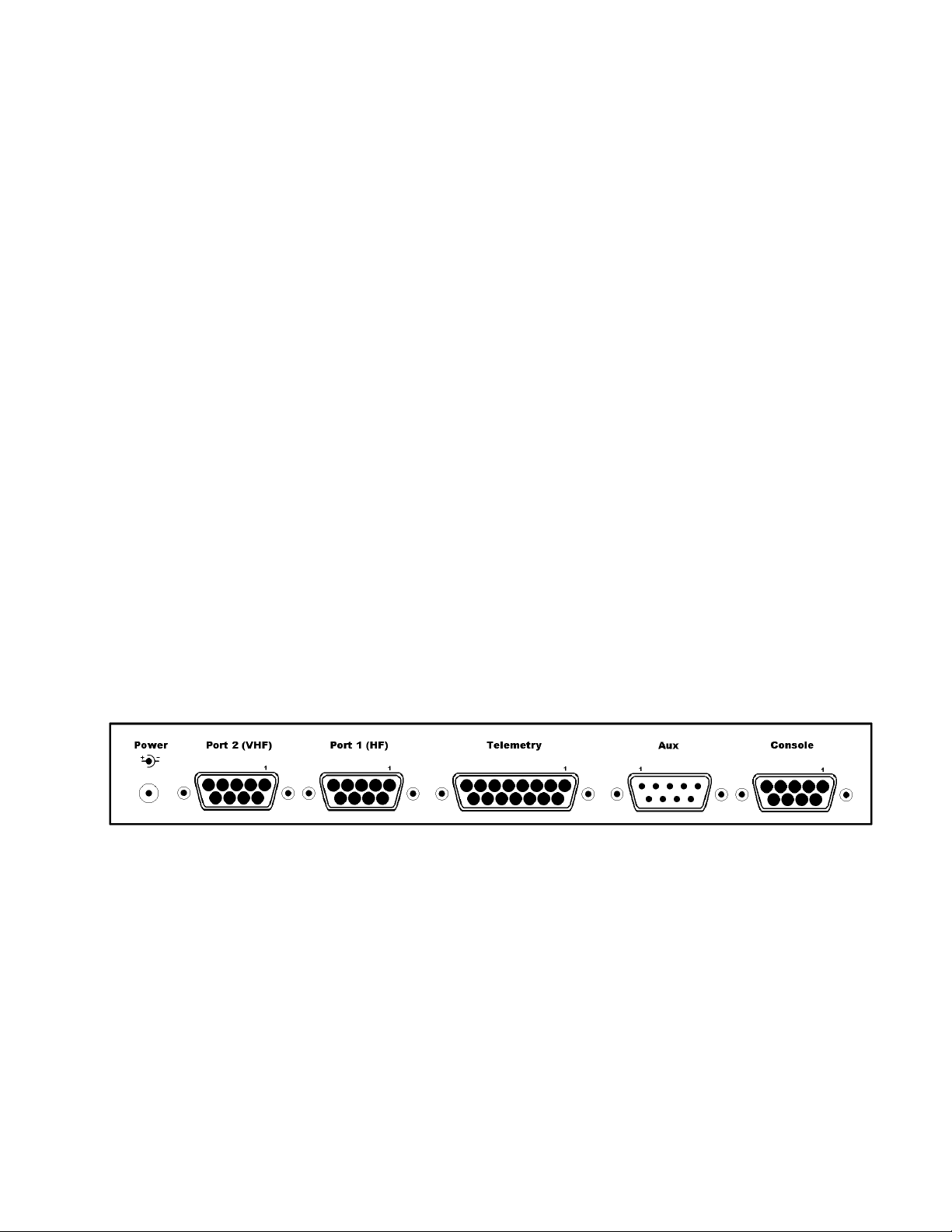
Rear panel of the KAM XL
The KAM XL rear panel has six connectors, which are:
Power jack (2.1 mm): for external power supplied from a dc power source (+9 to +18 V dc), center
positive.
Radio Port 2 (DSUB-9 female): accepts the cable from a radio, for 1200-baud packet operation.
Radio Port 1 (DSUB-9 female): accepts the cable from a radio, for HF or packet operation.
Telemetry (DB-15 female): an analog input port for connection to external sensing devices, which
provide voltages (from 0 to +5 V). Two control line outputs are also available on this port.
Page 19

19
AUX (DSUB-9 male): an RS232 DTE-type port, for data input from a GPS receiver, weather station,
(or similar device), or for RS232 communication to another device.
COMPUTER (DSUB-9 female): RS232 (DCE) for connection to a computer serial port, for control
of and communication with the KAM XL.
CONNECTING THE KAM XL TO A POWER SOURCE
A suitable power supply, such as a regulated dc power supply, an ac to dc power adapter, or a battery,
should provide +9 to +18 V dc at 100 mA (or more).
The power jack accepts a coaxial type plug, with a 2.1-mm center. The center of the plug is the
positive power connection.
Caution:
Exceeding the maximum input voltage or applying power with reversed polarity, can cause problems
operating the KAM XL or may cause damage to the unit or the power supply. When using a fused
power lead, do not use a fuse larger than 500 mA.
CONNECTING THE KAM XL TO A COMPUTER
To operate the KAM XL, the following is required:
A terminal device, or computer with an RS232 (or compatible) serial port that is available (not in use
by any other device).
A terminal communication program that will load and run in the computer’s operating system, and can
be configured to communicate through a serial port on that computer.
Note: If unsure about how to determine what serial (COM) ports the computer has, or how to make a
serial port available, consult the computer documentation and/or computer dealer.
The KAM XL does not require any specific computer program, and many different
communicationor terminal programs will work.
A simple (DOS) terminal program called PACTERM is available from the Kantronics web pages. It is
best used in DOS-only (by exiting windows to DOS), and can be used with standard COM-1 or COM2 serial ports.
Users of computers with Windows operating systems have other alternatives, such as TERMINAL in
Windows 3.1, HYPERTERM in Windows 95/98/Me, and Windows NT/2000/XP systems.
The Computer
Any computer that has an available (not used by any other device) RS232 serial port, and a terminal
program that can access that serial port, can be used.
Technical note: make sure the serial cable is wired as shown in the installation section below.
Standard type serial cables, such as those used to connect an external telephone modem to the
computer serial port, are correctly wired. If necessary, a cable can be assembled (wired as indicated
using shielded cable).
Page 20

20
The Serial Port of the Computer
On current models of PC-type computers, the serial port is usually a MALE DB style connector, with
9 or 25 pins. A FEMALE connector is needed on the computer-end of the serial cable, to connect
to the computer's serial port.
To use the KAM XL with a non-PC type of computer, use a serial communication program and a serial
modem cable normally used to connect a “HAYES” type high-speed telephone modem, to that
computer.
If the computer does not have an RS232 serial port available (or does not have one installed) but
does have USB ports, adapter devices can be found that will add an RS232 port through the
USB connection. However, this requires Windows 95 OSR2 with USB support, or a newer Windows
operating system, Macintosh (MAC) systems.
When requesting help from computer dealers or others, who may not be familiar with a packet radio
modem, refer to your KAM XL as an "external modem device," not as a "TNC," a less familiar term.
The Serial Cable
Use a standard RS232C serial cable, the same cable that would be used to connect an external-type
telephone modem to the computer serial port, or make a cable with the same wiring to connect the
KAM XL to a serial (COM) port on the computer.
When purchasing a cable, you should specify that:
The serial cable (RS232C) should be shielded, with at least 5 wires connected and 3 m in length.
See note 2 in the RF Interference section concerning shielded cable assemblies.
The modem end of the cable should have a male DSUB-9 connector (to connect to the KAM XL)
and the computer end of the cable should be a female DSUB-9 or DSUB-25 connector (depending
upon whether the computer’s serial (COM) port has a male DSUB-9 or DSUB-25 connector).
25 pin to 9 pin adapters are also commonly available, if a cable with the proper ends is not found.
When making a serial cable, these parts are needed:
A male DSUB-9 connector assembly (connector plug and metal or metalized plastic shell)
A length of shielded cable ( 3 m) containing at least five wires. See note 2 in the RF Interference
section concerning shielded cable assemblies.
Either a female DSUB-9 or DSUB-25 connector. Assembly depends on the connector on your
computer's serial (COM) port
Page 21

21
Serial Cable wiring:
If the computer serial port has a 9-pin connector, make these pin-to-pin connections:
Computer end
Modem end
Function
1 < 1
DCD
2 < 2
RXD
3 > 3
TXD
4 > 4
DTR
6 < 6
DSR
7 > 7
RTS
8 < 8
CTS
5 5
SG (signal ground)
Shield
Shield
Shield
If the computer serial port has a 25-pin connector, make these pin-to-pin connections:
Computer end
Modem end
Function
2 > 3
TXD
3 < 2
RXD
4 > 7
RTS
5 < 8
CTS
6 < 6
DSR
7 5
SG (signal ground)
8 < 1
DCD
20
>
4
DTR
Shield
Shield
Shield
Note: The shield must be properly terminated 360 to the connector. See note 2 in the RF
Interference section concerning shielded cable assemblies.
TXD is data from the computer to the modem
RXD is data from the modem to the computer
RTS is a flow control signal from computer to modem
CTS is a flow control signal from modem to computer
DSR is a control signal from modem to computer
DCD is a control signal from modem to computer
DTR is a control signal from computer to modem
SG is signal ground
The purposes of the pins (by name)
FG - FRAME GROUND: This pin is attached to the chassis of the equipment as a safety ground
TXD - TRANSMIT DATA: This line carries data output from the computer, to the KAM XL
RXD - RECEIVE DATA: This line carries data input to the computer, from the KAM XL
Page 22

22
RTS - REQUEST TO SEND: This hardware flow control line is controlled by the terminal
program in the computer, and is used to signal when it can or can not accept serial data from the
KAM XL
CTS - CLEAR TO SEND: This hardware flow control line is controlled by the KAM XL, to signal
when it can or can not accept serial data from the computer
DSR - DATA SET READY: This line is set high by the KAM XL to indicate that it is powered
ON
DCD - DATA CARRIER DETECT: the KAM XL to signal the status of the current I/O stream to
the computer uses this line. If a connection to another packet station exists on the current I/O
stream, this line will be active (positive voltage). If the current I/O stream is not connected (to
another station), the line will be inactive (negative)
DTR - DATA TERMINAL READY: Although interconnected via a buffer IC to the processor,
this line is currently ignored
Some terminal programs use or can be configured to use software flow control, and only three of the
connections are used, TXD, RXD, and SG (signal ground). However, all terminal programs, whether
using software flow control (using XON and XOFF) or hardware flow control (using RTS and CTS
lines in the cable), should work with the five wire connection in the cable as described above.
The computer or terminal is usually referred to as DTE (data terminal equipment). At this end of a
serial cable, TXD and RTS are output lines, and RXD and CTS are input lines.
The modem is referred to as DCE (data communication equipment). At this end of the serial cable,
TXD and RTS are input lines, RXD and CTS are output lines.
For data to flow from one device to another (DTE to DCE), output lines of one device are connected
to input lines on the other and vise-versa.
Installing the RS232 Cable
With an appropriate serial cable, connect as follows:
Step 1. Make sure that both the computer and KAM XL are powered OFF.
Step 2. Plug the male DSUB-9 end of the serial cable into the "Computer" port of the KAM
XL.
Step 3. Plug the female DSUB-9 or DSUB-25 connector end of the serial cable into a serial
port on the computer. The connectors can then be locked in place with their mounting screws.
Caution: Do not connect the serial cable from the KAM-XL to the computer’s parallel port. A parallel
port (i.e., printer, or LPT port) usually has female DSUB-25 connectors. The KAM XL cannot
communicate through a parallel port.
Once the cables have been connected and secured, the equipment can be powered back on.
Page 23

23
To verify that the serial cable is correctly wired and connected, use a terminal program or other
communication software in the computer, and configure it to communicate through the appropriate
serial port to establish communication with the KAM XL.
The Terminal Program
The serial port configuration in the terminal program should be set for 8 data bits, no parity, and one
stop bit. Terminal interface baud rates supported by the KAM XL are 300, 600, 1200, 2400, 4800,
9600, 19200 and 38400. In general, use the fastest baud rate that the terminal program, the computer
serial port, and KAM XL will support. The terminal program should be set for "full-duplex"
communication.
For operation with terminal programs using “half-duplex” communication, set the TNC command
called ECHO to OFF.
Some current model PC-type computers still come with high-speed serial ports already installed. In
older type computers, a serial port card with high-speed buffered UARTS should be installed to use
baud rates above 9600 baud. Serial port cards with high-speed buffered UARTS are available through
many parts suppliers and will improve the reliability of high-speed communications. Request a serial
port card with "high-speed buffered UARTS" (identified as 16550, or equivalent), when ordering from
a supplier.
If the computer did not come with an RS232 serial port installed, one must be added to be able
connect to the KAM XL. There are many makers of accessory serial port adapter devices to plug into a
USB jack. When acquiring one of these adapters, make sure it is designed to work with the operating
system in your computer, with drivers from the operating system supplier, or with drivers from the
device maker. Once installed and operational in the computer, the serial port device is addressed by
the operating system as a standard RS232 serial port number.
Page 24

24
CONNECTING THE KAM XL TO TRANSCEIVERS
To communicate with other stations, the radio ports of the KAM XL must be connected to a HF or
VHF radio (or both), depending on the type of communication desired. Radio Port 1 is for HF packet
and the other non-packet modes, and is normally connected to a HF SSB transceiver. Port 2 is for
Packet only mode, and is normally used with a FM transceiver (VHF, UHF, or HF 10 meter).
Parts for connecting the Transceiver
For the construction of a cable assembly from the KAM XL to a radio, 2 cable kits are included,
containing a male DSUB-9 connector plug and metalized plastic shell, and a length ( 0.91 m) of
shielded multi-conductor cable.
Connectors for the radio end of the cable are not included with the KAM XL.You will need to get the
proper connector to match the jack on the radio, to which you will connect the completed cable from
the KAM XL.
KAM XL Radio Port 1:
Will typically be connected to a HF (SSB, CW, or FM) transceiver, but could be used with a VHF
FM transceiver.
In a cable between Port 1 and a radio, at least four pins must be connected; transmit audio, receive
audio, PTT, and ground.
Transmit audio output should be connected to the microphone input (or transmit data input) on the
microphone jack of the radio.
Receive audio input should be connected to the external speaker output (or receive data output)
from the radio.
PTT should be connected to the transmitter keying line on the microphone jack.
Ground should be connected to a chassis ground of the radio.
If CW will be transmitted from the KAM XL, its CW key output line (pin 4) should be connected
to the CW key input on the radio (the same connection where a hand operated key would be
connected.)
A shielded cable must be used with the shield properly terminated 360 to the connector.
Instructions for making a cable assembly using the supplied foil shielded cable and metalized plastic
back shell follow:
1. Strip cable outer covering back enough to expose enough metalized plastic foil. Do not cut or
rip foil.
2. Carefully loosen the drain wire and foil from around the insulated wires.
Page 25

25
3. You will need to build up the diameter of the cable, where it enters the back shell, with any
type of tape or sleeve, so that when the metalized plastic shell halves are screwed together they
will hold the cable as strain relief and press against the metal foil.
4. Discard the metal strain relief pieces—they are of no use.
5. Connect wires as needed to terminals of connector.
6. Carefully fold the metalized foil back over the cable and Z-fold it so the metal side of the foil
is exposed to the connector back shell at the entrance area. Spread the foil over the cable so
you get as much coverage as possible (you will not get 360 coverage, but do the best you
can).
7. Place the drain wire in the gap where you can not get foil coverage.
8. Now place the metalized plastic shell halves together over the connector and cable. When you
screw the two halves together there should be enough compression to hold the cable in place
and there should be solid contact between the metal side of the foil and the metalized back
shell.
KAM XL Radio Port 2:
Will usually be connected to a VHF or UHF FM transceiver.
In a cable from Port 2 to a VHF radio, the same connections apply as from Port 1; transmit audio,
receive audio, PTT, and ground. Note that CW output is only available on port 1.
A shielded cable must be used with the shield properly terminated 360 to the connector.
See the instructions for making the cable assembly under Port 1.
Detailed descriptions of the radio ports on the KAM XL are located in the appendix sections.
Page 26

26
The Transceiver(s)
There are hundreds of models of FM transceivers, with many different wiring configurations and
connections. Refer to the documentation for the transceiver to determine how it can be connected to
other devices, or TNCs such as the KAM XL.
Specifically, determine what type of microphone connector or data plug to use, and which pins should
be connected in a cable between the radio and other devices.
AUX PORT (RS232 – DTE)
The AUX port is an RS232 serial port, for connection from the KAM XL to other devices. It is
configured as a DTE port, the same as a computers serial port.
It can be used for input from a GPS device, weather station, for interconnection to another TNC
communicating in NET/ROM mode in a node stack, or for communicating with other devices with
RS232 serial ports.
If the command GPSPORT is set to a baud rate greater than zero, the AUX port acts as input for
NMEA type data from a GPS receiver, or other device.
If the command NBAUD is set to a baud rate greater than zero, the AUX port is used to interconnect
with other TNCs in NET/ROM mode, at the specified baud rate.
CONNECTING A GPS DEVICE
To capture data from a GPS device, connect its DATA output to the AUX port on the back of the
KAM XL.
If the GPS receiver has a cable that can be connected to a computer serial port to report its position
data, the same serial cable can be connected directly to the AUX serial port of the KAM XL, without
changes.
Since cabling may vary from one GPS vendor to another, that cable is not supplied with the KAM XL.
To make a cable for connecting a GPS device to the KAM XL, at least 2 connections are required,
GPS data output and signal ground.
Connect GPS data output to pin 2 on the KAM XL AUX connector.
Connect GPS data ground to pin 5 on the KAM XL AUX connector.
The GPS data input to the AUX port on the KAM XL is enabled with its GPSPORT command.
Page 27

27
Interface Communication modes of the KAM XL
Terminal Mode
Terminal mode is the text-based command interface that allows operation of and communication with
the KAM XL from a terminal program or “dumb” terminal unit. In this mode, only one communication
mode can be used at any time, which could be Packet mode on either or both radio ports or one of the
non-packet HF modes instead.
However, when a non-packet mode is being used on the HF port, the VHF port can still be accessed
by other stations to use any of the active functions, such as the APRS digipeater, GPS data beacon,
PBBS, KA-Node, or K-Net node.
Kantronics Host Mode
Host mode provides a way of having more control of KAM XL, from a program that makes operation
easier and with more functionality than when using a simple terminal program. This allows sending
commands and receiving command responses, communicating over the radio ports in two modes at
once (connected and monitored 1200 baud packets and a non-packet HF mode.)
Communication between a program and the KAM XL in HOST mode uses frames of data. Each data
frame has a header which indicates the frame type (command, data, etc.), the radio port that data is
intended for or from, and sent or received data. The KAM XL retains all of its commands and
functions in Host mode.
Host mode uses Hardware flow control only, and requires that the serial cable that connects the KAM
XL to the computer include the RTS and CTS lines (as well as TXD, RXD, and signal ground).
Exiting Host mode
If a Host mode program has been used to operate the KAM XL, it may leave the KAM in Host mode
when it exits. If a standard terminal program is then used (set to the same interface baud rate) to
communicate with the KAM XL, instead of a “sign-on” message, some characters and SØØ will be
displayed. This is the Host mode current-status message.
The Host mode program should have an option to return the TNC to COMMAND or TERMINAL
mode, when that program exits. If the program is set to do this, other “standard” terminal programs
can then be used.
If the terminal program allows entry of high-numbered ASCII characters, a sequence of characters can
be sent to exit Host mode so the terminal program can then be used. First, send a FEND (frame-end)
character (ASCII code 192), then the letter q (upper or lower case is ok), and finally another FEND
character. A FEND character can be entered manually, by pressing and holding the ALT key, entering
192 from the number key pad on the right side of the keyboard (or in Hyperterm under Windows,
holding the ALT key and entering 0192), and then releasing the ALT key. The KAM XL will exit
Host Mode, will return to TERMINAL interface mode, and will display the usual Kantronics “signon” message.
Page 28

28
KISS Mode
Amateur packet radio communications can use the TCP/IP suite of protocols instead of AX.25 by
switching to TNC to KISS interface mode and running software that supports the KISS code designed
by Phil Karn (see references at end of this section). The KISS protocol specifies the communication
between a TNC and a host (e.g., computer).
KISS Mode allows the TNC to act as a modem and packet assembler/disassembler (PAD). In KISS
Mode, data processing is shifted from the TNC to a computer running special software supporting the
KISS code designed by Phil Karn. Very few of the KAM XL’s commands (and none of its other
functions), are available when it is in KISS mode. The operating functions that are available depend
solely on the computer program used.
KISS code supports higher-level protocols (i.e. TCP/IP) for sharing computer resources in a network
fashion. Examples of TCP/IP programs are NET, NOS, and JNOS. Also, some networking software
(G8BPQ) requires the KISS Mode of operation.
Technical Note: In the KISS Mode, the TNC simply passes all received data to the computer, and the
computer program is responsible for all processing of that data, including decisions concerning
routing, digipeating, and other control decisions.
The TNC converts the packets of synchronous data being received from the radio link into packets of
asynchronous data to be passed to the computer over the serial port, and converts the packets of
asynchronous data from the computer into the synchronous format suitable for radio transmission. The
TNC retains the responsibility of determining proper timing for channel access.
To place the KAM XL in KISS Mode, at the command prompt (cmd:), type INTFACE KISS and press
return. Then, send a RESET command, or cycle power (off/on) to the KAM.
The KAM XL will remain in KISS interface mode, until it receives the KISS exit code, or it has been
hard reset.
Exiting KISS mode
The TCP/IP program should include the command to EXIT KISS mode in the TNC. See that programs
documentation for the proper command.
To enter the EXIT KISS command manually (from a regular terminal program), send a three character
sequence which includes a FEND (frame-end) character (ASCII code 192), FF (ASCII code 255), then
another FEND character. A FEND character can be entered manually, by pressing and holding the
ALT key, entering 192 from the number key pad on the right side of the keyboard, and then releasing
the ALT key. The ASCII code 255 can be entered by pressing and holding the ALT key, entering 255
from the number key pad on the right side of the keyboard, and then releasing the ALT key.
The KAM XL will exit KISS Mode, will return to TERMINAL interface mode, and will display the
usual Kantronics “sign-on” message.
Otherwise, perform a HARD RESET. This will reset all commands to their factory default settings,
and allow the KAM XL to be re-initialized as a new unit.
Page 29

29
References on KISS Mode
Karn, P.: "TCP/IP: A Proposal for Amateur Packet Radio Levels 3 and 4", pp. 4.62-4.68 ARRL
Amateur Radio Computer Networking Conferences 1-4. Newington, CT: ARRL, 1985.
Chepponis, M. and Karn, P.: "The KISS TNC: A Simple Host-to-TNC Communications Protocol", pp.
38-42, 6th Computer Networking Conference, Newington, CT: ARRL, 1987.
XKISS (Extended KISS) Mode
The KAM XL also supports the G8BPQ multi-drop KISS Mode, called extended KISS (XKISS). With
this mode, the TNC can be connected to a G8BPQ node along with other TNCs on the same serial
port, to provide multiple radio ports to the node. Otherwise, XKISS works the same as KISS. For
information on this mode of operation, see the documentation for the XKISS software used.
Page 30

30
COMMUNICATION MODES IN THE KAM XL
The KAM XL is a multi-mode controller and/or Terminal Node Controller (TNC)
Packet Mode
Packet radio modems, or packet modems, are generally referred to as TNCs. This "label" or "moniker"
was adopted when the Tucson Area Packet Radio Group (TAPR) developed their first "TNC-1" packet
radio modem kit in the early 1980s. The TNC is the workhorse of packet radio. As a listening device it
hears an audio signal from the radio, changes the data to digital form, determines if the data is a good
packet and sends it to whatever device is attached, usually a computer. As a relay device it also checks
the packets it receives and determines if the packets need to be resent, then does so if appropriate. As a
sending device it receives digital data from the computer, packetizes the data, and converts it into
audio tones, which are sent out to the radio. The set of rules that all packet TNCs follow is called the
AX.25 protocol.
AX.25 Protocol for Amateur Packet Radio:
The most commonly used protocol in amateur packet radio is AX.25. The details of its inner workings
can be found in a book titled "AX.25 Amateur Packet-Radio Link-Layer Protocol", which is available
from the ARRL.
Connected vs. Unproto
There are two ways to send data in packet radio, connected or unproto (unconnected).
In the Connected Mode, a “connection” is established to another station. Packets are sent to that
specific station, and acknowledgments are expected in return that the packets were received correctly.
If an acknowledgment is not received, the TNC will re-send the data (depending on the setting of
AX25L2V2, it may send a poll first). The RETRY parameter will determine how many times this is
done before the connection is aborted due to bad conditions.
When acknowledgment is received, the TNC can then send more data. Therefore the Connected
Mode, barring impossible conditions, assures that the other station will receive all characters correctly
and in the proper order.
When the TNC sends a packet in the Unproto Mode, no acknowledgment is expected or required, and
no retries are attempted. This mode is often used for calling CQ, for transmitting beacons, and for
informal roundtable chats.
Monitoring and Calling CQ
When the MONITOR command is ON, packets heard from other stations can be displayed. The
display of monitored packets includes “header” and “data” parts. At the beginning of the header, two
callsigns are displayed separated by a ">". The first callsign is the station that transmitted the packet,
and the second callsign is the destination station that the packet is intended for. Unproto packets may
have any destination, but typically use CQ.
Page 31

31
When transmitting UNPROTO packets, the UNPROTO command sets the destination or “to” address
of those packets. Its default setting is CQ. Enter the Convers Mode to send a CQ message, by entering
the command CONV<CR> or K<CR>. Then, typed and entered characters will be packetized and
transmitted as data, and not be interpreted as commands.
To exit Convers mode and return to Command Mode, enter a <Ctrl+C>, by holding down the Control
key and pressing the "C" key.
A Simple Connect
To connect to another station, start from command prompt and enter a connect request. For example:
CONNECT callsign<CR>
Where CONNECT is the TNC command to establish a packet link with and another station, and
callsign is the callsign of the other station. If the connect request fails, the TNC will display the
following messages:
*** RETRY COUNT EXCEEDED
*** DISCONNECTED
When the TNC does receive an acknowledgment for a connect request packet, it will display the
message:
*** CONNECTED TO callsign
And will then change to the Convers Mode, or the communication mode defined by the settings of the
NOMODE and CONMODE commands.
Two commands determine when entered data will be packetized and transmitted. The command
SENDPAC defines the key or character that causes a packet to be transmitted. Its default setting is the
ENTER or RETURN key. Whenever that key is pressed, a new packet will be transmitted.
A second command called PACLEN determines the maximum number of characters to include in a
transmitted packet. When the number of typed characters is equal to the number defined by PACLEN,
a packet will be made and transmitted even if the ENTER key has not yet been pressed.
When the conversation with the other station has ended, the packet link to the station can be
“disconnected”. To disconnect, return to Command Mode with <Ctrl+C> and type a "D" for
Disconnect. Press the return or enter key after any command to the TNC. A Disconnect request packet
will be sent to the other station, and when an acknowledgement has been received back, the TNC will
display this message:
*** DISCONNECTED
And will return to command mode.
Either station can issue the disconnect command, no matter which station originated the connect.
Page 32

32
While connected to another station, the display of monitored packets will stop. To continue the display
of monitored packets, while connected to other stations, set the command MCON to ON.
Digipeating
TNCs can digitally-repeat or “digipeat” packets, to help other stations reach a destination station that
they can not hear direct. In Kantronics TNCs, the command that controls this function is called
DIGIPEAT and its default setting is ON. In many areas, a dedicated “DIGI”, consisting of a properly
configured TNC, a radio and antenna, are installed in a high location to provide digipeater capabilities
for many local stations.
When the command MRPT is set to ON, packets heard from digipeater stations will include callsigns
of the sending station and the intended recipient of the packet, and the callsigns of any digis used to
relay those packets. The list of digis used is often called the “path”.
The command called MYALIAS defines an alternate callsign or alias name of the digipeater. It is
typically set to a name that indicates a location or area of coverage of the digi, which is often easier to
remember than a callsign.
A station that needs to send a packet to another station it can not hear direct would address that packet
“VIA” a digi stations callsign or alias. Up to 8 digis can be used to relay packets to reach a desired
station.
To connect to another station VIA a digipeater, a command would be entered such as:
CONNECT KCØKON VIA LRNCE
Or if several digis are required,
CONNECT KCØKON VIA LRNCE,LVN,KCI
To send unconnected type packets like CQ messages or BEACONs VIA a digi, the UNPROTO
command is used to set the path,
UNPROTO CQ VIA LWRNCE
When digipeating, a packet is transmitted by the originating station, is re-transmitted by all relay
stations specified, to reach the destination station. That station would then respond that it received the
packet, by returning an acknowledgement packet by the same path to the original station. This is often
called end-to-end acknowledgment.
A special type of digipeater function for UI packets used by APRS stations is also available,
configured by its own set of commands. It is described in another section, called "Advanced
GPS/APRS digipeating.
Gateways
A Gateway Digi is a dual-port TNC, which allows packets heard on one of its radio ports, to be
relayed out from its other radio port. The radios attached to the ports of the TNC are usually on
different frequencies, or bands such as VHF/UHF or VHF/HF.
Page 33

33
Using a gateway digi is nearly the same as using a regular type digi. Transmitted packets VIA a
Gateway, are heard on one port of that TNC, and are re-transmitted out from the TNCs other port.
Multi-Connects
The KAM XL allows packet “connect” links (or streams) to as many as 26 other stations, on each of its
radio ports, at the same time.
The command MAXUSERS determines how many streams per port may be used at one time, and the
command USERS determines how many connect links from other stations will be accepted. Each
incoming connect is assigned to the next available stream. If the number of streams allowed by
USERS is full, a busy message will be returned to the next station attempting to connect, instead of a
connect acknowledgement.
By setting the USERS command to a lower number than MAXUSERS, the number of streams
between them will not be assigned to connect requests from other stations, and are reserved for
outgoing connects.
To determine which port and stream are the current “I/O”, to which keyboard input will be directed,
use the STATUS command. The report indicates which streams are currently active, and the current
“I/O” stream and buffer status.
To change streams, to make another connect or to direct data to another connected station on a
different stream, type the STREAMSW character, the number of the port (if different than the current
“I/O” port), and the letter designation of the desired stream. No return or enter key is necessary.
The setting of STREAMEV will then determine how often the stream designator is displayed with
received data. Setting it to ON will make the stream designators show on every connected packet
received. Setting STREAMCA also to ON will add the callsign of the "from" station beside the stream
designator.
Round Table Discussions
Several stations talking together, presents a difficult situation for packet radio since the protocol
requires two stations to connect to each other in order to make sure they receive each others packets.
To be absolutely sure that each station receives all transmitted data, a connect link would have to be
established to each station, and that data sent to each station in turn.
Selective Monitoring
With MONITOR ON, the BUDLIST command can be used to limit the display of monitored packets
from other stations, to only those packets FROM (or TO, or both) a specific station or any of to 10
callsigns listed.
Timing
Dwait vs. Persistence and Slottime
Page 34

34
When the TNC acts as a digipeater, received packets that need to be relayed are retransmitted as soon
as the frequency is clear. Other TNCs on frequency (should) hold off or wait their turn, using a
PERSISTENCE/SLOTTIME algorithm or DWAIT method to determine when to transmit. This
practice has been adopted to reduce collisions with packets being digipeated, since these packets must
(by the AX.25 protocol) be acknowledged end-to-end. The use of the PERSIST/SLOTTIME algorithm
to gain channel access is standard in Kantronics’ TNCs. The default value for DWAIT is set to zero. If
the DWAIT method is used, the TNC sending non-digipeat packets will wait for DWAIT (times 10
ms) time of clear channel before beginning to key-up the radio to transmit.
The algorithm used with the settings of the PERSIST and SLOTTIME parameters, helps avoid packet
collisions by randomizing the wait time before transmitting. By using this random timing, it is less
likely that any two TNCs will transmit at the same time, and causing a packet collision. When a TNC
has a packet to transmit and detects that the channel is clear, it will wait SLOTTIME (times 10 ms),
and generate a random number. If resulting number is smaller than the number specified by the setting
of PERSIST, the TNC will transmit. If the number is larger, it will wait another SLOTTIME and then
generate another random number and again decide whether to transmit or not.
When using PERSIST/SLOTTIME, DWAIT should be set to 0, since both will be used if specified.
As an example, assume that PERSIST is set to 63, and SLOTTIME is set to 10. This value of
SLOTTIME results in a random number being generated every 100 ms. When the TNC sees that the
channel is clear, it waits 100 ms then generates a random number between 0 and 255 (inclusive). If, in
this example, the number was 83, then the TNC would not start the key-up of the transmitter since 83
is greater than the 63 PERSIST value. Instead, it would wait an additional 100 ms, and if the channel
is still clear, generate a new random number. This time, let's say it comes up with the number 27.
Since this is less than the PERSIST value, the key-up of the transmitter to send the packet will begin.
TXDELAY
TXDELAY should be adjusted to allow sufficient time for the radio to switch from receive to transmit
and develop full power output. If the TNC starts sending packet data before the transmitter has
reached full power, the beginning of the packet won't be heard by other stations, and the packet will be
lost. TXDELAY also allows sufficient time for other stations receiver and TNC to become active and
detect a received packet signal.
The TNC sends only flags during the TXDELAY period. Flags are not part of a packet or data to be
decoded. When TXDELAY is set extra long, the flags preceding a packet can be heard.
FRACK (Frame Acknowledgment Time)
If the TNC expects an acknowledgment of a packet it has sent, it will wait FRACK seconds for the
acknowledgment. If the acknowledgment is not received it will either send a poll or retransmit the
packet, depending on the setting of AX25L2V2. When digis are used, extra time is allowed for each
transmission using the following equation:
FRACK * ((2 * n) + 1) s
where n is the number of digipeaters. The lower the baud rate (HBAUD) the higher this parameter
should be set, because everything is slower. The length of the transmission (determined by PACLEN
and MAXFRAME) also needs to be taken into account when deciding how to set FRACK. Longer
packets (and more of them) require more time to be transmitted, more time to be repeated by the
digipeater, and so on down the line. The FRACK timer begins when PTT is released (the packet has
Page 35

35
been sent) and is suspended when data carrier from the radio is present, or when your station is
transmitting.
Retries in AX.25 Level 2, Version 1 vs. Version 2
The way retries are accomplished depends on AX25L2V2 being OFF or ON. If a packet is transmitted
to a connected station, and an acknowledgement is not received back, the entire packet is retransmitted
(with the same frame number) up to the number of tries specified by the RETRIES command, until an
acknowledgement is received. If acknowledgement is still not received, a disconnect sequence is
started, up to the number of RETRIES again. If there is still no response from the other station, the unacknowledged packet is discarded. In level 1 type responses, single pairs of angle brackets are used
(such as <rr0>).
Under version 2 (AX25L2V2 ON), when an acknowledgement has not been returned, a POLL only is
sent (not the entire packet), up to the number of times specified by RETRIES. In level 2 type
responses, two pairs of angle brackets are use (such as <<rr0>>).
Convers Mode vs. Transparent Mode
In the Convers Mode special characters are recognized by the TNC. They are used to edit typed data
before transmitting it, to pass through special characters as data to another station, or to cause a packet
to be transmitted.
Transparent Mode was designed for sending files, whether ASCII data files or program files. Special
characters (other than TRFLOW and TXFLOW when ON) have no meaning to the TNC in transparent
mode, they are just characters to be put in a packet and sent to the radio.
In Transparent Mode, the PACTIME command defines when packets are transmitted. There is no
MONITOR function while in TRANSPARENT mode. Only data from a connected station can be
received.
Exiting Transparent Mode
Since Transparent Mode allows the sending of all characters, only a special sequence of characters or
a modem break will exit Transparent Mode. The command called CMDTIME sets a timing of
character entry, that will allows the use of the COMMAND character in the special character
sequence. Three COMMAND (<Ctrl+C>) characters must be entered within CMDTIME of each
other, with at least one CMDTIME before and after the special sequence.
Some terminal programs can send a MODEM BREAK signal, which toggles the TXD line for a
specific period of time that is longer than a standard character bit time. This will also cause the TNC
to exit TRANSPARENT mode, as long as its command BREAK has not been set to OFF.
Flow Control
Both the computer and the TNC have fixed amounts of input (and output) buffer space. Flow control
prevents the loss of data in communication between the computer and a TNC. If one of the devices has
a nearly full input buffer, it can signal the other device to stop sending data until it has been able to
process the data it has already received.
Page 36

36
Software Flow Control
Software flow control uses special characters, as defined by the commands XOFF, XON, STOP, and
START, which are inserted into data on the TXD and RXD lines between the computer and TNC. One
of the devices will send a <Ctrl+S> to signal the other device to stop sending data and a <Ctrl+Q> to
signal that it can resume sending data. Software flow control can be disabled, by setting the command
XFLOW to OFF. The commands TRFLOW and TXFLOW are used to enable software flow control in
TRANSPARENT mode.
Hardware Flow Control
Hardware flow control uses the RTS and CTS lines in the RS232 cable. The TNC will de-activate the
CTS line to the computer, to signal it to stop sending data. The computer will de-activate the RTS line
to signal the TNC to stop sending data.
Remote Access
The commands of the KAM XL can be accessed remotely from another TNC, as long as its commands
MYREMOTE and RTEXT have been set. MYREMOTE defines the callsign or name for the remote
access feature, and RTEXT is a password character string.
In a local TNC, command it to connect to the MYREMOTE callsign in the remote KAM XL. It will
respond to the connect request, with three lines of six numbers per line. Pick one of the lines, and enter
the characters at the positions indicated in the line, as entered in RTEXT.
As a simple example, enter the command RTEXT aBcD. Since there are only 4 characters in the line,
the numbers returned in the three lines of six numbers, in response to a connect request to the
MYREMOTE, will only be 1 to 4, such as:
1 1 3 2 4 2
2 1 4 4 3 1
4 3 1 2 4 1
Selecting the first line, the return entry would be:
aacBDB
Upper and lower case characters must be entered exactly the same as they were in RTEXT, numbers
and spaces also count as a character.
When remote command access has been granted, a prompt: (instead of cmd:) will be returned, and
commands to the remote TNC can then be sent. Any command that causes a reset to occur, will lose
the connection in the remote TNC, the same as when cycling its power off and back on, leaving the
local TNC still thinking it is connected to that remote station.
Proper care should be used when changing commands remotely, as some commands can cause that
remote TNC, or any TNC for that matter, to stop communicating completely.
If three password attempts are made and failed when linked to the MYREMOTE callsign, it will
disconnect and will not respond to connect requests for 15 min.
Page 37

37
There is a limitation on the amount of data that can be returned from the remote TNC while using its
remote access. Responses are limited to 300 characters or less, so some commands will not fully
display their response. In response to the command DISPLAY, only the first 300 characters of the full
display listing will be returned. But the setting of any single command can be displayed in its entirety.
When finishing a remote access session, send the command to the remote TNC:
DISC MYREMOTE
The remote TNC will then send a disconnect packet back to the local TNC. The local TNC can also be
commanded to disconnect from the remote TNC, by returning it to its command prompt and entering
the DISC command.
The same password entry sequence is also presented when connecting and requesting SYSOP access
to the PBBS or K-NET node from another station.
Other Packet Modes of Operation
PBBS (Personal Mailbox)
The KAM XL includes a Personal Bulletin Board System (PBBS or mailbox), which is capable of
storing messages for local display, and/or forwarding messages to another PBBS or BBS for other
users. This PBBS provides many of the same message handling functions as a computer based packet
radio full-service BBS, including the forwarding of Bulletins, Private mail, and NTS traffic (for more
information on the national network of full-service PC-based packet BBS systems, see a current
ARRL operations manual).
The personal mailbox is compatible with the large community bulletin board systems (RLI, MBL, etc)
and will allow them to forward messages directly into your TNC. Messages to other stations can be
placed messages in the mailbox, and if the local Community BBS system allows, will be picked up
(reverse forwarded) from the personal mailbox into the BBS system on request.
The PBBS can also be configured to automatically connect to the community BBS (again, if that
system allows) and forward any messages to or through that system.
Using the PBBS
In order to use any Kantronics TNC PBBS (even your own), first get the cmd: prompt, and then
connect to the callsign of the PBBS. For instance, if the MYPBBS is set to use the callsign NØKN-1,
connect to it by typing "CONNECT NØKN-1". In this example, the PBBS is in this TNC, and will
respond to the local terminal the same way it would respond to any other station connecting to it over
the radio.
The TNC will display a message indicating that a connection has been made to the callsign of the
PBBS:
*** CONNECTED to NØKN-1
Page 38

38
The PBBS will then display its SID and initial sign-on message. The SID is enclosed in square
brackets and consists of the unit name, firmware version, and the supported features (i.e. HM$). The
supported features in the PBBS of the KAM XL are Hierarchical forwarding, Message ID, and BID.
These identifiers are the SID definitions published by Hank Oredson (WØRLI) with his Community
BBS system.
If a PTEXT has been defined, the TNC will send it as the next line, and then send the PBBS command
prompt. For example, the PBBS in the KAM XL will respond with the following:
[KAM-XL-1.0-HM$]
102400 BYTES AVAILABLE
(PTEXT would be here, if it has been entered)
ENTER COMMAND: B,J,K,L,R,S, or Help >
Connecting to any Kantronics TNC-based PBBS would result in a similar prompt sequence.
At this point the PBBS is ready to display messages, accept messages to other users, allow editing of
messages already entered, display help information, etc.
Entering Messages
To enter a message addressed specifically to another user, who can connect to the PBBS and read the
message later, use the Send Private command:
SP KBØNYK
and the TNC responds with:
SUBJECT:
enter a short subject line:
Just a quick question…
The TNC responds with:
ENTER MESSAGE n-END WITH CTRL-Z OR /EX ON A SINGLE LINE
where "n" is the next available message number in the mailbox. Enter the text of the message. At the
end of the message, press the return key to begin a new line, and type a <Ctrl+Z> or /EX to end and
save the message. The <Ctrl+Z> or /EX must be on a line by itself. When the message has been ended
properly, the PBBS responds with:
MESSAGE SAVED
ENTER COMMAND: B,J,K,L,R,S, or Help >
The PBBS is again ready to accept commands.
Page 39

39
When the PBBS is connected to any station, the Mail LED on the front panel will be lighted. When
the PBBS is not connected, and contains unread messages addressed to the MYCALL, MYPBBS, or
any of the callsigns or names entered in the PBLIST command, the Mail LED will blink.
The PBLIST is also used with the PBPERSON command and the following PBBS commands:
LMINE, KMINE, and RMINE.
PBBS Commands
The commands available to users connected to the PBBS are as follows:
B(ye)
Causes the PBBS to disconnect.
E(dit) n [BPTYNFH] [>tocall] [<fromcall] [@BBS] "old" "new"
Available only to the system operator (SYSOP) or to a user at the keyboard of a computer
connected directly to the TNC (i.e., not to a remote connection, except for the SYSOP). For an
explanation of this command, see the section below on "Editing Message Headers."
H(elp)
Displays a HELP menu.
J(heard)
Displays a list of stations recently heard by this TNC. The list will include a date and time
stamp indicating when each station was heard.
J(heard) S(hort)
Displays only the callsigns of stations heard.
J(heard) L(ong)
Displays the callsigns of stations heard and any digipeaters used and the destination callsign.
L(ist) [ x [y]] [; ]
Lists all messages in the mailbox allowed to be read. This will include all BULLETIN and
TRAFFIC messages, and any PRIVATE messages addressed TO the TNCs callsign or
messages that were sent from this TNC. The SYSOP of the PBBS (keyboard or remote) can
list and read ALL messages. Optionally, the list can be started from a specific message
number, and end with at another specific message number, i.e. x = START # and y = END #.
Also, including the optional semi-colon (;) in any List command will also show the @BBS and
BID (BULLETIN ID - see section on "Sending Messages") of the messages (if any).
L(ist) <|> call [ ; ]
Lists only those messages in the mailbox which are addressed to a specific callsign (>), or
which were sent by a specific callsign (<). To list only those bulletin messages addressed to
AMSAT for instance, enter the command L >AMSAT.
LB [;]
Lists all BULLETINS in the mailbox.
Page 40

40
LC [cat [;]]
The LC command by itself, will cause the PBBS to list only the TO field of all BULLETINS
in the mailbox. If a category is specified (i.e. LC RACES) the PBBS will list the full message
headers of all BULLETINS addressed TO that category.
LLn [;]
Lists the most recent n number of messages in the mailbox that the current user is allowed to
read.
LM (ine) [ ; ]
Lists all messages in the mailbox which are addressed to the user currently connected.
LO [+|-]
Sets the order in which messages are listed. When set to +, the messages are listed in ascending
numerical order (oldest to newest). When set to "-", the messages will be listed starting with
the highest message number (newest to oldest). The listing order can not be changed if the
PBLO command is set to FIXED.
LT [;]
Lists all TRAFFIC messages.
K(ill) n
Deletes message number n from the mailbox. You may only delete TRAFFIC messages,
PRIVATE messages addressed TO or FROM you, or BULLETINS you sent. The SYSOP may
delete any message, including BULLETINS.
KM(ine)
Deletes any messages marked as READ addressed to the current user. Messages marked as
NOT READ, will not be deleted.
R(ead) n
Reads a specific message by number. Only PRIVATE messages addressed TO or sent from the
current user, and any BULLETIN or TRAFFIC messages, may be read. PRIVATE messages
addressed to the current user will have the STATUS flag set to Y, when read.
Using RH instead of R will include the message headers as well as the other information
provided by the Read command. The message header contains the date/time the message was
received at each forwarding BBS that forwarded the message.
RM(ine)
Displays all unread messages addressed to the current user.
S(end) call
Sends a PRIVATE message to the callsign specified. Using S(end) is the same as using the SP
command.
SB cat
The SB (Send Bulletin) command is used to send a BULLETIN addressed to the specified
category.
Page 41

41
SP call
The SP (Send Private) command is used to send a PRIVATE message to a specified callsign.
Using this command is the same as using the S(end) command.
ST zip
The ST (Send Traffic) command is used to send NTS type traffic messages to the PBBS.
Some of these commands are described in more detail below.
Sending Messages
The SEND command (and its many forms) allows the following syntax:
S call [@ bbcall [.haddr]] [$ mid]
SP call [@ bbcall [.haddr]] [$ mid]
ST zip [@ location [.haddr]]
SB cat [@ location [.haddr]] [$ bid]
where:
call is the callsign of the station the message is addressed to.
bbcall is the callsign of a full service BBS to deliver the message to.
haddr is the complete Hierarchical address designator for the BBS system or destination of the
message (see the section below on "Hierarchical Addresses" for more detailed information).
Contact a local community BBS SYSOP for complete information on local Hierarchical
addressing.
location is the designator used for distribution of the message. For TRAFFIC, this should be
NTSxx where xx is the two letter POSTAL code for the state.
mid is the MESSAGE ID assigned to the message by the originator.
bid is the BULLETIN ID assigned to the message by the originator.
zip is the 5 digit postal zip code (or postal code).
cat is the message category. For instance, a message requesting help on a subject may be sent
to the category HELP, info sent to INFO, items for sale to SALE, etc.
Contact a local community BBS SYSOP for some other examples and suggestions.
When sending a message to the PBBS, it must include the @BBS (bbcall [.haddr]) field if the
message is to be forwarded from the PBBS to a full-service BBS system. Any message entered into
the PBBS over the radio will initially be marked with a status of H (held) and will not be allowed to be
forwarded, until the SYSOP has edited the message header and changed the H flag. This gives the
SYSOP full control over the relayed messages from the PBBS. Messages entered from the local
keyboard connected to the TNC do not require editing in order to be allowed to be forwarded, but
must include at least an @BBS field to enable the reverse forwarding.
Page 42

42
Listing Messages
When listing messages with any of the LIST commands, a display will be similar to the one shown
below. If the optional semi-colon (;) is specified in the list command, the display will also include the
@BBS field (if it exists) in square braces after each line.
MSG# ST SIZE TO FROM DATE SUBJECT
6 B 45 KEPS W3IWI 10/19/01 09:37:11 2 Line Element set
4 B 26 HELP WB5BBW 10/19/01 09:34:05 Xerox 820
3 T 38 66044 WØOUU 10/19/01 09:33:42 QTC Lawrence 913/842
2 PN 14 NØAPJWØSC 10/19/01 09:33:27 AMTOR
1 B 30 ALL KCØKON 10/19/01 09:32:49 Need help on AMTOR
102120 BYTES AVAILABLE
NEXT MESSAGE NUMBER 7
ENTER COMMAND: B,J,K,L,R,S, or Help
The message number (MSG#) is listed, followed by the STATUS of the message. This status includes
the message type (B=Bulletin, T=NTS traffic, and P=Personal message). The second character in the
ST column is the current status of the message.
A Bulletin status (type B) can be:
F -it has already been forwarded to another full-service BBS.
H -it is being held for review by the SYSOP because it was entered into the PBBS over the
radio.
An NTS traffic message (type T) may have a status of:
H -indicating that it is being held for review by the SYSOP before it may be forwarded.
The Private message (type P) can have the following status characters in the second position:
H -This is a personal message that has an @BBS field but is being held for review by the
SYSOP before it may be forwarded.
N -This message is a Personal message that has not been forwarded and has not been read by
the station it is addressed to. If it is forwarded to a full-service BBS, it will be deleted if
PBKILLFW is ON.
Y -This message has been read by the station it is addressed to, but has not been killed. It will
not be forwarded even if it has an @BBS since it has already been read.
Editing Message Headers
The following command can be used to edit message headers:
E(dit) n [BPTYNFH] [>tocall] [<fromcall] [@BBS] "old" "new"
Page 43

43
This command, available only to users with SYSOP access, allows the editing of headers and content
of any message in the mailbox. Sysop access is automatic when connecting from a local terminal, or
can be granted to remote users connecting to the PBBS over the radio, by password control. See the
section titled "Remote Sysop Access to the PBBS" for more detail.
The TYPE of the message:
B - Bulletin
P - Private
T - Traffic
The STATUS of the message:
Y - Yes [it has been read]
N - No [it has not been read]
F - Forwarded [it has been forwarded]
H - Held [it is not available for reverse forwarding]
Note: F and H are toggles. Entering F switches the status of the message from F to NOTF or from
NOTF to F. Similarly, entering H switches the status of the message from H to NOTH or from
NOTH to H.
Who the message is to or from:
>tocall
<fromcall
The destination mailbox (@BBS):
@BBS [.haddr]
And the subject or text of the message:
In the message, replace the FIRST occurrence of the string "old" with the string "new". When a
message is listed, the "tocall" and "fromcall" appear in the TO and FROM columns, respectively. If a
message has been entered with an "@BBS" for forwarding, the complete hierarchical address is shown
when the message is read:
MSG#2 02/10/92 10:30:58 FROM KBØNYK TO HELP @WA4EWV.#STX.TX.USA.NOAM
The @BBS is also listed when using the semi-colon (;) option with any of the list commands.
The Edit command can be accessed by connecting to the mailbox from the attached terminal, or by
connecting over the radio. When connecting over the radio, SYSOP privilege must gained by giving
the SYSOP command as the first command sent to the PBBS. When giving the SYSOP command, the
PBBS will return a password verification string, to which the proper response must be given, in order
to gain SYSOP access. This is explained in detail later.
Page 44

44
Reverse Forwarding Messages from the Mailbox
The TNC mailbox will allow entry of messages to be forwarded to a full-service BBS (RLI, MBL,
etc). These messages have a special format, and can be entered in any personal mailbox.
Entering an @ BBS in the address of a message, will make that message available to be forwarded or
reverse forwarded to a full service BBS. Including the HIERARCHICAL address of the destination
BBS, will improve the chances of the message to be delivered properly.
Forwarding a message is when the TNC PBBS automatically connects to a full-service BBS and sends
messages to be passed through the BBS system to another station.
Reverse forwarding happens when a full-service BBS connects and sends messages to a TNC PBBS,
then asks for and receives any messages from the PBBS to be passed to another station via the BBS
forwarding system.
If the command PBKILLFW has been set to ON, successfully forwarded messages will be deleted
from the PBBS.
Bulletin type messages will be marked with a status of "F" and will remain in the PBBS.
Note: To enable forwarding or reverse forwarding from the PBBS, the Hierarchical address of the
PBBS must be entered in the HTEXT command, which is required for complete return addressing
capability in forwarded messages.
Hierarchical Addresses
Hierarchical addresses are used to accommodate the national packet traffic system, including
messages processed by PC-based packet radio BBSs.
The HTEXT command sets the Hierarchical address of the TNCs PBBS. This is used whenever the
PBBS forwards mail to another BBS to provide complete return addressing capability. A hierarchical
address consists of state, country, and continent codes, separated by periods. Some areas, particularly
in large states, may also use sub-state designators.
Complete information on Hierarchical forwarding can be obtained from a local BBS station or system
operator. Basically, the first field after the @ symbol is the HOME BBS of the destination station, to
which the message is being sent. The next several fields are the Hierarchical address. They include
designators for (sub-state), state, country, and continent.
Other PBBS features include the ability to select whether or not to kill private and traffic messages
after they have been forwarded, and whether or not to HOLD messages received over the radio.
The PHEARD command will show the callsigns of stations that recently connected to the mailbox
along with their start and stop times.
Page 45

45
Advanced PBBS Configuration
When the TNC is first initialized, and its callsign has been set, the PBBS will automatically be
enabled and the PBBS is allocated 100K bytes of RAM. The MYPBBS callsign is set to be the same
as the TNC callsign, but with a different SSID of -1.
The size of the PBBS may be changed using the PBBS command. The maximum amount of memory
available to allocate to the PBBS will depend on the amount of free memory available. NUMNODES,
MAXUSERS, and MYREMOTE, etc. will affect the amount of available memory.
Changing the size of the PBBS will not cause existing messages to be re-numbered. If the new PBBS
size is still large enough to contain existing messages, none of them will be lost.
To renumber all existing messages in the PBBS, beginning at number 1, re-enter the PBBS size to the
same as the current size. Enter the PBBS command alone first, to find its current size.
Most of the TNC functions remain active, even when the terminal is turned off or disconnected from
the KAM XL. When this is the case, other stations connecting to the MYCALL of the KAM XL can be
sent to the mailbox automatically, to leave a message or read messages addressed to them.
Before exiting the terminal program, set the command CMSG to PBBS. The CTEXT command can
also be set to inform the connecting station that the user of the TNC is not available at this time, and
the mailbox will answer instead.
A custom greeting message, as specified by the PTEXT command, can be included in the sign-on of
the PBBS and sent to users connecting to the PBBS. The PTEXT message can contain a text string of
up to 128 characters.
The TNC owner can send the DISCONNECT MYPBBS command, that will cause the PBBS to
immediately disconnect from a connected station.
If a station has connected to the PBBS, but no activity occurs on the connection for 15 min, the PBBS
time-out timer will automatically disconnect the user, to make the PBBS available to other stations.
If a community bulletin board forwards messages into the PBBS, it will include the routing headers
which are the lines beginning with "R:". The routing headers show the complete path taken by the
message. By default, these headers will be stored with each message. To conserve mailbox space, all
but the last routing header can be thrown away, by setting the command PBHEADER to OFF.
To set the PBBS to accept only those messages addressed to the TNCs MYCALL (or MYPBBS, or
calls or names in the PBLIST), set the PBPERSON command ON.
Finally, the PBLO command is used to determine the order in which messages are listed to a user.
When set to OLD, listed messages will be sent in the order of oldest to newest. When set to NEW, the
list will be newest to oldest. When the option of FIXED is added, the user cannot change the listing
order, and when set to VARIABLE, the user may change the order by sending the LO command.
Page 46

46
Remote SYSOP Access to the PBBS
Users of the PBBS through a radio connection can gain remote SYSOP access by entering the SYSOP
command as the first command after connecting to the PBBS.
Upon receiving the SYSOP command from a remote user, the PBBS will return three lines of five
numbers each. These numbers indicate the character positions in the RTEXT command. This is the
same password access query, as when a remote user connects to the MYREMOTE callsign.
Routing Lines
Under current FCC requirements, BBS systems that can store and forward messages without an
operator being present, must have the capability to provide a record of the path the message has taken
from its origination. To accomplish this, BBSs include a routing line, beginning with "R:". This "R:"
line includes the date and time the message was received, message number, BBS callsign and
hierarchical routing information.
When reading messages using the RH command, the complete header of the message is displayed,
including the routing lines. If the command PBHEADER has been set to OFF, only the last routing
line is saved with forwarded messages.
Page 47

47
KA-NODE
Overview
The KA-Node is a simple packet-networking node. When enabled, this station can be used by other
stations, not only as a digipeater but also as a node, helping them to find pathways to other stations
that they can not reach.
KA-Nodes, like other networking nodes such as NET/ROM, operate more efficiently than do
digipeaters as a link between two stations. End-to-end acknowledgement of received packets is not
required with the nodes; instead they handle errors between each other, rather than from end to end
(which can cause extra traffic when errors or interference occurs). A KA-Node, however, is "silent" in
that it does not automatically connect to and exchange routing data with adjacent nodes, as do fully
featured nodes such as NET/ROM, X1J, or Kantronics K-Net.
Consequently, users cannot issue a connect to a distant station without knowing the path - as they
sometimes can with a fully featured node. At the same time, KA-Nodes are useful in that they are
more efficient than digipeaters in using channel time, while not requiring the effort and time required
to maintain a full-function network node.
Configuring The KA-Node
The following commands are used to configure the KA-Node: NUMNODES, MYNODE, NDWILD,
KNTIMER, and KNXCON.
The command NUMNODES, when set to a number greater than zero, enables the KA-Node. The
number sets the number of circuits (channels) allowed through the KA-Node. Each circuit consists of
a connect "IN" from a station to the node, and a connect "OUT" from the node to another station. Each
KA-Node circuit allowed will require approximately 4.3K of memory.
If an attempt is made to set NUMNODES to a value requiring more memory than available, a message
indicating that the value is out of range will be displayed. The total number of circuits that can be
allocated will be affected by the amount of memory allocated to the Personal Mailbox and other TNC
functions.
The callsign assigned to the KA-Node, by the MYNODE command, must be different from the
callsigns used for the TNCs other functions, such as MYCALL, MYALIAS, MYPBBS,
MYREMOTE. By default; the TNC sets the MYNODE to the callsign that was used to initialize the
TNC, with an SSID of -7.
If the command NDWILD has been set to ON, the KA-Node will accept connect requests to any SSID
of its callsign (MYNODE), except those already assigned to the TNCs other functions.
Packets passing through the KA-Node are monitored and displayed, unless the MYNODE callsign is
included in the SUPLIST command.
If it becomes necessary to disconnect a station from the KA-Node, issue the command DISCONNECT
MYNODE x, where x is the number of the channel to disconnect.
Page 48

48
The command KNTIMER sets a timeout, to clear inactive connections. If no data passes through a
circuit for n min, then that circuit (connect in and out) will be disconnected. The default time is 15
min. The timeout function can be disabled by setting n to 0.
The setting of the command KNXCON, when set to ON, allows connecting stations to connect out on
the opposite port of the TNC.
Using a KA-Node
The KA-Node function is for use by other stations. When a station connects, the KA-Node will return
its command line, which is similar to the command line of the PBBS. The commands available are B,
C, J, N, or Help?. X will be included if the KNXCON command is ON. Preceding the command line,
will the text specified in the command NTEXT, if entered.
The command B is for BYE. When it is received, the KA-Node will disconnect.
The command C is for CONNECT. It is entered with the callsign of a destination station, to which the
node is to connect. If the optional S (for STAY) is included after the callsign, the KA-Node will
remain connected to the station that connected IN, after the destination station has been disconnected.
The command J is for JHEARD (stations heard). When received, a list of callsigns of stations from
which packets were recently heard by the TNC, which contains the KA-Node, will be returned. If the
optional L (for LONG) is included with the J command, the list will include dates and times the
packets from those stations were heard, the destination callsigns in the packets they sent, and any
digipeaters used. The format of the date and times in the list, will be as specified by the TNCs
DAYSTRING command.
The command N is for NODES heard. When the TNC hears ID packets from other stations, that
include a callsign with a /N, that callsign is included in the Nodes heard list. If no /N callsigns have
been heard in any ID packets, the response will be NO KNOWN NODES. As with the J command, the
optional L will return more information about those stations heard.
The command H is for help. When received, the Ka-Node will return a list of short descriptions for its
available commands.
Using the XCONNECT Command
The X command, for cross-connect, is a unique feature of the KA-Node. It allows cross-linking
between two frequencies through the node in much the same manner as the Kantronics unique
gateway, but with local acknowledgment of packets.When a connecting station wishes to connect to a
station that can be reached through the other port of the TNC, he sends the X {callsign} command.
The TNC will then attempt to establish a link with that station on its other radio port.
Determining Which Port You Have Connected To
When connected to a multi-port node, the JHEARD command can be used to determine which port of
the node you have connected to. A typical node response to the JHEARD command may be displayed
as shown (a KAM Plus would use /H and /V instead of /1 and /2):
N66046/2* 11/01/2001 14:32:69
NØKN-1/1 11/01/2001 16:25:01
Page 49

49
WØXI/2 11/02/2001 16:28:05
KCØKON/1 11/02/2001 16:32:09
In this illustration the number following the slash (/) indicates the port the station was heard on. Your
callsign will usually be the last one in this list.
You can now see that by comparing the port on which your call appears in the JHEARD list to the port
indicated for other stations, you can determine whether to CONNECT or XCONNECT to the station
of your choice.
The X command, for cross-connect, is a unique feature of the KA-Node. It allows cross-linking
between two frequencies through the node in much the same manner as the Kantronics unique
gateway, but with local acknowledgment of packets.
Remote Commands of the KA-Node
When accessed by radio, the KA-Node has several commands available. These commands are listed
here for reference, with a description of each command. In these descriptions, the UPPER case
characters of the command are required, while LOWER case characters are optional. Those items
listed within [ ] are optional and if used the UPPER/LOWER case convention applies.
ABORT
Aborts a KA-Node Connect or Xconnect request if it is the first data sent after the connect request. It
must be spelled out entirely.
Bye
Causes the KA-Node to initiate a disconnect.
Connect callsign [Stay]
Causes the node to issue a connect request to "callsign" in the usual AX.25 mode. If the connect is
successful, a link will be made to the next node or end-user station called. The optional Stay feature
provides a way to disconnect without loosing the entire link. Normally when a disconnect occurs,
whether issued by you or by the remote station, the connection to the KA-Node is also lost. Using the
Stay option allows you to stay connected to the KA-Node when the remote station issues a disconnect.
Help
Causes the KA-Node to send a brief help list, showing all commands available, with the options and a
short description of each command.
Jheard [Short|Long]
Causes the KA-Node to return its MHEARD (stations heard) log.
The short (JHEARD S) version of this command would produce the same list, without dates and
times.
Page 50

50
The long (JHEARD L) version of this command will include date/time stamp, the destination field,
and any digipeaters used.
Nodes [Short|Long]
Causes the node to return a list of KA-Nodes it has heard, as well as K-Net, G8BPQ, NET/ROM and
TheNet nodes. The format of the list is similar to that of the JHEARD list above.
Xconnect callsign
Causes the node to issue a connect request to the specified callsign, on the opposite port of the KANode.
Page 51

51
K-NET
The K-NET node is an advanced network node, compatible with other network nodes, such as
NET/ROM, THE-NET, and G8BPQ.
When the K-NET function is enabled, other stations can connect through it to other network nodes, or
direct to a destination station.
Network nodes work together to configure a constantly updating network system, to aid individual
packet stations in making contacts with distant stations they can not reach directly.
The advantage of a network node system is two fold: automatic routing of connections to other
network nodes, and increased data throughput. A network node "knows" how to automatically route
data through neighboring nodes to distant nodes on the network. They do this by "hearing" other nodes
broadcast this information. This means that a user connected to a node does not need to specify the
particular route to take in order to reach a distant node as long as the local node contains a listing for
that distant node. Using a network node can also dramatically increase the data throughput to distant
locations. The packet data and the acknowledgements travel from node to node (rather than from endto-end), greatly reducing the inevitable data collisions that will occur when attempting to
communicate over long distances.
The defacto standard networking protocol, NET/ROM, was developed in the late 1980's by Software
2000, Inc. Since then, other node derivatives such as TheNET, TheNET Plus, TheNET X1-J, and
G8BPQ evolved. Although these variants differ in their features, they all utilize the same basic
networking protocol.
The K-Net feature adds the function of a dual-port network node to the operation of the KAM XL. All
normal functions of the KAM XL can remain active, including PBBS operation, dual-port (packet)
operations, and remote access. This means that the KAM XL can still be used in normal operation,
while also providing the local area with a dual-port network node that operates in the background of
normal TNC packet operations.
K-Net is fully compatible with the basic network protocols, and provides two ports that can be added
to existing networks. It also supports the NET/ROM interface communication, through the AUX
connector, and can be connected to a node stack.
K-Net Configuration
The factory default values in the KAM XL have the network node function disabled. To enable the KNet node, the NETALIAS and NETCALL commands must be entered. NETALIAS is usually set to a
mnemonic that gives users an idea about where the node is located (other network nodes do not care
what the alias name is).
For example, LAW is a good NETALIAS for a network node installed in an area including the city of
Lawrence, Kansas. The NETCALL is the callsign of the network node. It consists of a valid callsign
and SSID (such as NØKN-10), and must be different from any other callsign used in the KAM-XL, for
its other functions. Entering a callsign in the NETCALL command will cause a soft reset as memory is
allocated for the node operation.
Several of the network node configuration commands can only be changed while in command mode.
Changing the parameter values of any of these commands (NETBUFFS, NETCIRCS, NETDESTS,
Page 52

52
ETLINKS, NETROUTE, and NETUSERS) will also cause a soft reset, as memory is allocated for
their use. Their functions and parameter value ranges are listed in the command section.
Other K-Net node parameters can only be accessed or changed, while connected to the node as sysop.
Unlike the KA-Node, which can not be accessed from the local terminal, a K-Net node will accept a
connect request from the local terminal, allowing sysop access to change the network node parameter
settings. Just send a CONNECT command to the NETALIAS or NETCALL callsigns, and the
network node will respond in the same way it would respond to a user from another TNC.
To gain SYSOP access when connecting to the node from another TNC, the first command sent to the
node must be the SYSOP command. The same password entry must then be sent, in the same way as
when requesting SYSOP access to the PBBS or MYREMOTE.
Upon connecting to the node, it will not return a command line or node prompt, but simply sending a
carriage return (pressing the ENTER key) will cause a display of the node commands available. To
see the current setting of any node command, type that command name and ENTER.
A short description of any command is available, by entering Help (or ?) and the command name.
Short descriptions of all available node commands, will be returned by the HELP HELP command.
Once the node has been enabled, some of its text messages should be set, to provide other users with
helpful information about the K-Net node. First, connect to the node as sysop, and enter each
command (CTEXT, INFO, or PORTS) followed by text messages.
CTEXT, for connect-text, is sent when a station connects to the network node. It may be a greeting
message, followed by short instructions about how to get more help about the node operation.
INFO, or node information, could be a message indicating the location of the node or its coverage
area, and node equipment (such as TNC type, radios, etc.).
PORTS, or port information, could be a message indicating the channels in use by the radios that are
connected to each port of the TNC, and baud rates available.
Note: To successfully integrate any new network node into an existing network system, efforts should
be made to coordinate with neighboring network node sysops. Many of the parameter settings of each
individual node, will affect the operation of the entire network system, and if set to conflicting values,
can degrade performance of the node network.
Networking terms
NODE - The term node, refers to a network node such as a G8BPQ, X1-J, or NET/ROM node. Nonnetwork nodes such as a KA-Node, conference bridges, and digipeaters, do not apply to this concept
of operation.
USER - A user is either a real live person using a TNC to connect to and use the network node, or a
server (BBS) that is basically doing the same thing under computer control.
NEIGHBOR NODE - A neighbor node is another nearby node that can be heard and connected-to
direct, without using an intermediate node. Note that digipeater operation is allowed (2 max.). This
means that a node can be "out of range", but can still be considered a neighbor since the connect path
Page 53

53
does not use any other nodes. All known neighbor nodes (those nodes from which nodes broadcasts
are heard direct) are displayed with the ROUTES command.
DISTANT NODE - A distant node is a node that is too far away to connect to "direct", and requires
the use of one or more network nodes to reach. Distant nodes will not be displayed by the ROUTES
command.
DESTINATION NODE - A destination node is a node that your node knows how to connect to either directly as a neighbor node, or by using one or more intermediate nodes. All known destination
nodes (neighbor nodes, and distant nodes) are displayed with the NODES command.
All neighbor nodes are destination nodes, but all destination nodes are not necessarily neighbors.
Destination nodes will automatically appear in the nodes table by virtue of monitoring their nodes
broadcasts. A neighbor node will automatically be listed in the nodes table and routes table. Neighbor
node broadcasts also contain information about other nodes that they can hear. These distant nodes
will also be listed in your nodes table if they pass the criteria for being listed, by the setting of the
MINQUAL command, and if there is sufficient room for them to be listed, as set by the NETDEST
command.
K-Net SYSOP Commands
These system operator (SYSOP) commands are available to the user at the keyboard attached to the
KAM XL, when connected to its network node callsign. The same commands can be accessed from
another packet station, after gaining sysop access (by entering the SYSOP command, and entering the
correct password characters, as set in the RTEXT command).
ADDNODE [alias:]call port neighbor [VIA digi1[,digi2]] quality [obscent]
Adds the specified new destination node, or modifies the entry of an existing destination node
in the nodes table. If the optional obscent (Obsolescense Count) is set to 0 (zero), the node will
be permanently listed in the nodes table and will not be updated or dropped from the nodes
table by the K-Net auto-routing logic. If the neighbor node callsign entered is not in the
neighbor routes table, it is added with the default quality for the specified port. As long as
MINQUAL is equal to or less than QUALITY, destination nodes (neighbor nodes as well as
distant nodes) will be added automatically to your nodes table as neighbor node broadcasts are
received.
Example - ADDNODE KSLAW:NØKN-10 2 KCØKON-1 200
K-Net node responds: NODE ADDED WITH NEW ROUTE
ADDROUTE port call [via digi1[,digi2]] quality [!]
Adds or modifies the specified NETCALL of a neighbor node in the routes table. If the
optional ! is included, the route entry is either locked if unlocked, or unlocked if locked , (i.e.
toggle). An existing locked route does not have to be unlocked before it can be modified.
Locking a neighbor's route is used to assure that an assigned quality will always exist for that
neighbor. The locked quality will also be used in the automatic quality computation of other
distant nodes contained in this neighbor's node broadcasts to determine if they should also be
added to your nodes table. In the event that this locked neighbor disappears from the network,
Page 54

54
for whatever reason, and then returns, it will automatically be assigned the locked quality.
During the time that this neighbor is absent, it, and distant nodes associated with this neighbor,
may eventually be removed from the nodes table (even if the route is locked) because the
obsolescence count for this neighbor node could drop to zero. If this neighbor's route is locked,
it will still be listed in the route table, but with a zero count for destination nodes using that
route.
EXAMPLE – entering the command: ADDRoute 1 WD0EMR-1 110 !
K-Net responds: Route added and locked
This adds the route to the WD0EMR-l node to the route table in the K-Net node. The route is
"locked in" and assigned to port 1 with a quality of 110.
Locking a route assigns a fixed quality to a neighbor node. This can assure that any connects to
a distant node using this neighbor node as a route will take the "hard coded" route, even if the
route automatically generated by the K-Net node is different, such as may occur during band
openings.
CQBC [ON|OFF/ON|OFF]
Default ON/ON
When set to ON for either or both radio ports, allows users to send CQ broadcasts from the
node.
CTEXT [text] up to 128 characters
The connect message text sent to stations upon connecting to the NETALIAS callsign (but not
when connecting to the NETCALL). Can be cleared by entering CTEXT %.
DELNODE [alias:]call port neighbor [via digi1[,digi2]]
Deletes the specified destination node from the nodes table. The entry must match the current
entry in the list exactly, or the node will not be deleted.
DELROUTE port call [via digi1[,digi2]] quality
Deletes the specified neighbor node from the route table. The entry must match the current
entry in the list exactly, or the node will not be deleted. A neighbor node can not be deleted if
there are any other nodes in the nodes table using this neighbor as a route.
INFO [text] up to 128 characters
Enters an information message, which is usually a description of the node location or area of
coverage, and/or equipment list. It can be cleared by entering INFO %.
IDINT n/n (n = 0 - 255)
Default 10/10
Page 55

55
Sets the interval, in number of minutes, of the node ID beacon from each port of the node. This
is not a nodes broadcast, just an ID. Setting either or both numbers to 0 (zero), turns off the ID
beacon.
L3TTL n (n = 0 – 255)
Default 25
Sets a limit on the maximum number of times a packet originated by an uplink station
(normally an end user) at this node may be transferred through other nodes. Each time a
message is handled by a node, the time-to-live for that message is decremented. If the L3TTL
counter reaches 0 (zero), the message is discarded. It is possible for network nodes to create
circular paths, and therefore a limit is required to prevent a packet from relaying in the node
system forever.
L4DELAY n (n = 1 – 60)
Default 5
Sets the delay time in number of seconds after the node has received a level 4 frame from
another node, before an ACK is returned. This allows a combined packet of the ACK and any
data that may be ready to be sent to the same destination, to be sent together. Thus, sending
only one frame instead of two or more.
L4LIMIT n (n = 0 65,535)
Default 900
Sets a “no-activity” timeout timer, in number of seconds, on a node crosslink. When a user
connects to another node, the node first establishes a level 2 (AX.25) connect with that node,
and then establishes a level 4 circuit on behalf of the user. When the user is finished, the level
4 crosslink is closed but the level 2 connection remains until the L4LIMT is reached, at which
point is terminated.
When a user disconnects, the level 2 connection between the nodes remains intact and the
L4LIMIT time is restarted. This decreases data congestion if another crosslink request using
the same path occurs before the L4LIMIT expires, since the node will not have to re-establish
the level 2 connect.
L4N2 n (n = 1 – 127)
Default 3
Sets the number of retries used to pass Level 4 data between nodes in the system. After the
L4N2 count reaches 0 (zero), alternate paths will be tried.
L4T1 n (n = 5 – 600)
Default 120
Page 56

56
Sets the time, in number of seconds, that the originating node will wait before resending a level
4 data packet if no acknowledgment is received from the destination node (end-to-end info-
ACK). If set to small, multiple copies of the same packet can exist within the node system,
even if the first packet was received correctly.
L4WINDOW n (n = 1 – 127)
Default 4
Sets the maximum number of outstanding frames that may exist in the network, for a given
circuit. When the node has L4WINDOW un-acknowledged frames, it will not transmit any
more frames until a level 4 info-ACK is received. Network nodes may allow up to 127
outstanding frames across the system. The L4WINDOW size is negotiated between nodes
when a crosslink is requested; therefore its size should be standardized network-wide.
MINQUAL n (n = 0 – 255)
Default 70
Sets the minimum quality required to add a destination node to the nodes table.
NODESINT n (n = 0 – 255)
Default 60
Sets the time interval, in number of minutes, between node broadcasts. It should be set to an
agreed-on interval, the same as all nodes in the network system.
OBSINIT n (n = 0 – 255)
Default 5
Sets the initial obsolescence value that is assigned to destination nodes. When a nodes
broadcast is transmitted, the obsolescence value for each listed destination node, is decreased
by one. When a node is listed in a nodes broadcast heard from another node, the obsolescence
value for that node is increased by one. If the obsolescence value for a listed destination node
drops below the OBSMIN limit, that node will not be included in nodes broadcasts. If the
value drops to zero, the node will be removed from the nodes table, unless it had been added
(by ADDNODE) to the nodes table, with an obsolescence value of zero.
OBSMIN n (n = 1 – 255)
Default 4
Sets the minimum obsolescence value, which will allow a destination node to be included in
nodes broadcasts.
QUALITY n/n/n (n = 0 – 255)
Page 57

57
Default 255/70/110
Sets the quality assigned to neighbor nodes, when their nodes broadcasts are heard, on each
port. The first number is for nodes broadcasts heard though the AUX port, when it is connected
directly to another TNC and communicating in NETROM mode (NBAUD >0). The second
number is for nodes broadcasts heard through port 1, and the third number is for port 2.
K-Net USER commands:
These commands are available to any user connecting to the network node callsign in the KAM XL,
from another packet station.
BYE
Causes the node to disconnect from the user that issued the command.
BBS [/S]
Causes an internal connect to the PBBS in this TNC. When the /S option is included, will
remain connected to the node after exiting the PBBS.
CONNECT [[port] call|alias [/S]]
Commands the node to connect to another node or enduser. When the /S option is included,
will remain connected to the node after disconnecting the current link.
CQ [UI text]
Commands the node to broadcast the specified text.
DISPLAY
Displays a list of current node parameter settings.
HELP
When entered alone, displays a list of all commands available to the connected user. When
entered followed by the name of a specific command, will display a short description of that
command. Entering “HELP HELP”, will display short descriptions of all available commands.
INFO
Displays the information message that was entered by the SYSOP. It is usually a description of
the node location or area of coverage, and/or equipment list.
LINKS
Displays a list of current AX.25 links existing in the node, including the callsigns of the linked
stations, the AX.25 STATE, the port number, the TYPE of link, and the AX.25 version.
Page 58

58
The AX.25 STATEs are: 1 for DISCONNECTED, 2 for CONNECT IN PROGRESS, 3 for
FRMR CONDITION DETECTED, 4 for DISCONNECT ATTEMPT IN PROGRESS, 5 for
CONNECTED, 6 for WAITING ACKNOWLEDGEMENT, 7 for DEVICE BUSY, 8 for
REMOTE DEVICE BUSY, 9 for BOTH DEVICES BUSY, 10 for WAITING
ACKNOWLEDGEMENT and DEVICE BUSY, 11 for WAITING ACKNOWLEDGEMENT
and REMOTE DEVICE BUSY, and 12 for WAITING ACKNOWLEDGEMENT and BOTH
DEVICES BUSY.
The TYPEs of links are: U for UPLINK, D for DOWNLINK, or X for CROSSLINK.
MHEARD [LONG|SHORT]
Displays list of callsigns recently heard on each radio port of the node. Including the LONG
option will also include the destination callsigns and any digipeaters used, and the time stamp.
NODES [{* | alias | call}]
Displays the list of all known destination nodes. The list includes the ALIAS and CALLSIGN
of each node. If the optional * is included with the command, hidden nodes are also shown,
and are marked with #. Entering the command and specifying a node alias or callsign, will
display up to three possible routes (neighbor nodes) of descending quality that will be used to
establish a link with a specified destination.
PORTS
Displays test messages about the radio ports, that were entered by the sysop.
ROUTES
Displays a list of neighbor nodes, including radio port number, node callsign, quality value, the
number of destination nodes, if the route is in use, and if the route has been locked in by the
sysop.
STATS
Displays a summary of statistics concerning level 3 and level 4 activity on this node.
SYSOP
Command to request SYSOP access to the node. User must respond to the password query,
using the password characters defined by RTEXT. See the remote access section.
USERS
Displays a list of users currently connected to node, the number of buffers currently available,
uplinks, downlinks, and crosslinks.
Node Stacking
Page 59

59
More radio ports can be added to this network node. The added TNC must be set to communicate
through its serial port in Net/rom mode, at the same baud rate. The KAM XL communicates in
Net/rom mode through its AUX port. Setting the TNC command NBAUD to a baud rate matching the
serial port baud of the other TNC activates the Net/rom interface mode.
When connecting to just one other TNC, a standard serial cable is all that is needed. When connecting
to a node stack, a diode matrix is required.
NOTE: NBAUD and GPSPORT cannot be enabled at the same time. The AUX port of the KAM XL
can be used for only one function at a time. Attempts to enable both functions at the same time will
return an error message.
Page 60

60
GPS NMEA, Weather station Interfacing
The KAM XL can be interfaced with a GPS device that provides data in the NEMA-0183 interface
standard, to weather stations that have a compatible data output. It has a complete set of commands to
configure and control unproto (path) retransmissions of the NEMA strings, and can provide RAM
storage for location messages (strings) for later retrieval.
Overview
The U.S. Department of Defense, to provide worldwide positioning and navigational information for
U.S. military forces developed the Global Positioning System (GPS) initially for military use. Since
then, a broad range of commercial, civilian, and amateur radio applications has been developed, based
on the GPS.
The GPS consists of 24 satellites, each of which transmits positioning information continuously. GPS
receiving units - devices that contain a receiver, LCD display, and (usually) a data port - collect this
positional information and use it to compute position. This information can then be retransmitted by
any means possible to report the position of the GPS device (and its vehicle).
Most GPS units sold today are NMEA compatible. That means that not only can they display latitude,
longitude, and time on an LCD screen, but that information can be output through an RS232 or
compatible port. This port can then be connected to the serial port of a computer or TNC.
The GPS position information is presented in a special format of sentences of ASCII characters as
specified by a protocol called NMEA-0183. A number of these sentences are available with varying
kinds of information, but the ones used most often for amateur radio activities are $GPGGA, and
$GPRMC. These sentences contain information such as latitude, longitude, altitude, and time (in UTC,
derived from the satellite clocks). The TNC, in GPS Mode, can capture this data and store it in a
buffer, and retransmit it in beacons and/or record them in a large tracking buffer for later retrieval.
The TNC, while in GPS Mode, can also update its internal date/time clock to UTC, derived from the
satellites.
When connected to a weather station, the KAM XL can capture (and beacon) the weather data strings,
just like GPS data, using the same GPS commands and settings.
GPS Equipment Requirements
To set up a packet GPS station to beacon GPS data for mobile position reporting, the following
equipment would be needed:
a transceiver and antenna,
the KAM XL,
a GPS unit, with an attached or external antenna, that has an RS232 or compatible data output in
NMEA 0183 format, with a cable to connect to another device.
Page 61

61
Cabling a GPS Unit to the KAM-XL
The NMEA standard specifies that the signals in the GPS receiver data port follow the EIA-422
standard.
Technical note: Many GPS vendors simply use "TTL" voltage levels (+5 V and 0 V,) but use the
same polarity as RS232 signals. These units are capable of supplying proper input to the AUX port of
the KAM XL. However, some GPS vendors invert the sense of this signal (true TTL), and these units
will not directly interface with an RS232 port.
Warning: The KAM XL serial ports use RS232 voltages, which are + and - approximately 8 V. Check
the GPS device manual before attempting to connect it to another device. If it includes a cable and/or
indicates that it can be connected directly to the computers serial port, it can be connected directly to
the AUX port of the KAM XL with the same cable. Kantronics is not responsible for damage to the
TNC by incorrect connections to other devices, or connection to incompatible devices.
To connect the data port of a GPS unit to the KAM XL, a cable with at least two wires is required. A
shielded cable is preferred. Refer to the GPS manual to determine which pins are used for signal
ground, and data output. If the GPS device requires an initialization string input, a third wire for data
input to the GPS would also be needed.
Connect the signal ground wire of the GPS data port to pin 5 of the KAM XL AUX port. This wire
may be identified as "NMEA-" by some GPS vendors.
Connect the data output of the GPS data port to pin 2 of the TNC serial port. The data output pin may
be identified as "NMEA+" by some GPS vendors. This line supplies the GPS NMEA sentences to the
TNC.
Some GPS units may have a data input to allow for configuring their data output. If so, this is
accomplished by passing commands to the GPS unit from a terminal or TNC, via an additional wire in
the data cable. If this is the case, connect the third wire of the data cable from the input data pin of the
GPS data port to pin 3 of the AUX port. Again, consult the GPS manual for the name of this pin, as
pin names and functions vary by vendor. Also, make sure this pin will accept an RS232 signal (+ and voltages).
Most GPS devices that have a data output have a default configuration with standard type output
sentences. They may never need any data input or configuration. In this case, a two-wire cable is
sufficient, to connect them to the KAM XL
Configuring the GPS Commands
Several commands are used to configure the KAM XL to capture and beacon, or store GPS data.
GPSHEAD selects the GPS string or up to four different strings to be captured and stored in the
Location Text (LT) buffers. The entry is case sensitive, so be sure to enter the sentence header in the
correct case. Most, if not all, NMEA sentence headers are in CAPITAL letters. The GPSHEAD for LT
buffer 1 is set to $GPGGA by default. To configure buffer 2 to store the sentence beginning with
GPRMC for example, enter the command as; GPSHEAD 2 $GPRMC.
Page 62

62
BLT sets the beacon interval rates for each of the four LT buffers. To beacon LT buffer 1 at every 1min interval, enter the command as; BLT 1 E 00:01:00. To clear the buffer every time it has been
beaconed (so that old non-updated data is not transmitted more than once), include the optional
parameter CLEAR after the time interval. If both ports of the KAM XL have been enabled, and are
currently in Packet mode, the LT buffers can be beaconed from either one or both radio ports (and at
different intervals, if desired).
LTP sets the digipeater paths for each of the LT buffers. Many digipeaters, that re-transmit UI-type
packets to other APRS monitoring stations, use callsigns such as RELAY or WIDE. To set LT buffer
1 to be re-transmitted by any WIDE digipeater, enter the command as; LTP 1 APRS VIA WIDE.
GPSPORT enables the AUX port for GPS data input (and output) at the specified baud rate. Many
GPS devices have a data output baud rate of 4800.
LTRACK allocates TNC memory for a GPS data storage buffer. Any one or up to all four LT buffers
can be stored for later retrieval. The LTRACK buffer is then accessed through connection to the
PBBS. If more memory is desired for a larger LTRACK buffer (or for other functions), the PBBS size
can be decreased. But, it the PBBS must remain enabled with at least 1K of memory allocated to it, so
that the LTRACK buffer can be accessed.
If the GPSHEAD string for any LT buffer is empty, that LT buffer can be set up as an auxiliary
beacon, manually entering text in the that buffer, and setting BLT and LTP to beacon that text at the
specified interval via the designated path.
GPS Device Initialization from the TNC
Some GPS receivers require input of a special string of characters for initialization before they will
output any information. The TNC can be configured to send the initialization string to the GPS unit by
entering the required string using the GPSINIT command. For instance, if the GPS receiver requires
the initialization string $PGRMO,GPGGA,1, the command would be entered as:
GPSINIT $PGRMO,GPGGA,1
Upon power up of the TNC, or after a soft reset has been performed, that string is output from its
AUX port to the GPS unit.
Other GPS Features
Slotted Beacons
The BLT command provides for the ability to specify not only the interval between beacons, but also a
starting time for the beacons. This permits a "slotted" system of beacons by numerous stations. For
instance, if the local area has 30 stations that each should beacon their location every 30 min. A
beacon would be transmitted every n minutes from the time the user sets the time that the beacon
should be transmitted. As an example, if BLT has been set as;
BLT 1 EVERY 00:30:00 START 00:00:01
The beacon would not start transmitting until 00:00:01 after midnight and then every 30 min after that.
A second user could set the BLT with the command:
Page 63

63
BLT 1 EVERY 00:30:00 START 00:01:01
In this case, these two users beacons would never be transmitter at the same time, but would beacon 1
min apart. Using this system as an example, it would be possible to set all thirty users to beacon 1 min
apart, avoiding collisions.
Tracking Without Beacons
To configure the TNC to only store the LT beacons in the LTRACK buffer, without transmitting them,
set the LTP to NONE for the associated LT buffer. As in:
LTP 1 NONE
When the destination call (path) is set to NONE, the TNC will not transmit the beacon, but since the
BLT command is still active, the data will be stored in the LTRACK buffer, at the BLT specified
interval.
Remote Access and GPS
When connected remotely to the TNC through its MYREMOTE callsign, and have properly
responded to the password security check, any parameters can be changed, including the GPS
parameters.
If the GPSPORT command has been enabled, by setting it to a baud rate greater than 0 (zero), text can
sent out through the AUX port at its configured baud rate by sending the RPRINT command.
For example, to send the configuration string “$PGRMO,GPGSA,1” to a GPS unit that is connected to
the AUX port, enter the command:
RPRINT $PGRMO,GPGSA,1
This requires that the DATA input to the GPS device be connected to the data output from the AUX
port. The string does not, in fact, have to be destined for a GPS device. The device attached to the
AUX port could be any type of device that accepts RS232 input.
Other Notes
The LT buffers, LT beacons and LTRACK buffer can be used even without a GPS unit attached. Any
text can manually be entered in the LT buffers, up to 128 characters total, using the LT command as
in:
LT 1 This is LText buffer number 1
The LT buffers will be transmitted based on the BLT and LTP commands and stored according to the
LTRACK command even when the TNC GPSPORT has not been enabled.
Page 64

64
Other text can be specified in the GPSHEAD command. If the data input to the AUX port is in the
same format as NMEA data, that begins with a specific character or word and ends in a CR/LF
(carriage return/linefeed) sequence, it can be stored in the LT buffers. Some weather station devices
operate in this manner to report weather information.
GPS Command Summary
The following GPS commands are listed here for convenience and explained in detail in the
Command Reference section.
BLT n {EVERY|AFTER} hh:mm:ss [START hh:mm:ss] / {EVERY|AFTER} hh:mm:ss
[START hh:mm:ss] (n = 1 - 4)
Sets the interval between beacons for the associated LT string, for either or both radio ports.
GPSHEAD n string (n=1-4) (up to 8 chars)
Determines which GPS NMEA sentences will be stored in the LT buffers.
GPSINIT string (up to 128 characters)
Specifies a text string that will be sent to the attached GPS unit upon power-up.
LT n text (n = 1 - 4) (up to 128 chars)
Enters the specified text in the associated LT buffer.
LTP n dest [via call1[,call2,...]] / dest [via call1[,call2,...]] (n = 1 - 4)
Sets the destination callsign and any digipeaters to be used when transmitting the LT buffers.
LTRACK n [LT1] [LT2] [LT3] [LT4] [SYSOP] [TIME]
Allocates memory for a special tracking buffer used to store LT messages.
RPRINT text (up to 128 characters)
This is an immediate command, which sends the specified text string from the AUX port to the
attached device (e.g. GPS unit).
GPS Device Manufactures and vendors
Garmin, 1200 E. 151st St., Olathe, KS 66092
ICOM America, Inc., 2380 116th Ave. N.E., Bellevue, WA 98004.
Magellan Systems Corp., 960 Overland CT., San Dimas, CA 91773.
Sony Electronics Inc., 1 Sony Dr., Park Ridge, NJ 07656.
Page 65

65
Trimble - Mobile Computing Products, 645 N. Mary Ave., P.O. Box 3642,
Sunnyvale, CA 94088-3642.
Advanced GPS/APRS Digipeating
A common goal of mobile position reporting stations is to have their UI packets digipeated over a
wide area or long distance, while moving though areas where the local digipeater callsigns may be
unknown. An effective solution for not knowing local callsigns is to establish standard generic
callsigns for digipeating stations and then use these names in digipeating paths. Of course, this
requires the acceptance and use of standards for naming and using digipeating stations, by both the
position reporting stations and the digipeating stations.
Common standards have been established by some local APRS groups to use digipeater names such as
RELAY, WIDE, TRACE, and GATE. Check with a local GPS or APRS group before configuring the
TNC with its UI digipeater capabilities. Digipeater naming conventions, and frequency usage may
vary by area.
Improving Efficiencies of Advanced Digipeating
As described above, mobile location reporting stations use digipeating paths containing generic
digipeating names (e.g., RELAY, WIDE, TRACE) to extend their range of reporting. Using generic
digipeating enables a mobile station to use the same digipeating path as it moves around, since there
will (presumably) always be nearby GPS/APRS digipeating stations with one or more of these generic
names to pick up transmissions of UI packets, and re-transmit them to a wider area or on a different
radio channel.
Using generically named digipeaters does result in wider coverage of GPS stations, but several
inefficiencies may arise from this common practice (depending upon the availability and names of the
digipeaters).
Among the problems that may arise in this situation, are:
(1) UI packets can be repeated much more than necessary, by the same or by different digipeating
stations with the callsigns RELAY, WIDE, or TRACE clogging up the airwaves,
(2) and that several stations may re-transmit the same packet at the same time, resulting in a multiple
transmissions that cannot be copied by other stations.
The command UIDUPE has been added to TNCs with UI digipeating. Its use is to make a check to see
if a heard packet has already been digipeated. If it has already been digipeated, this unit will not make
extra repeats of the same packet.
Kantronics' TNCs have a suite of UI digipeating commands that can be used to deal with inefficiencies
that can arise when a number of digipeaters using the same generic names are located in the same
area, and can transmit at the same time.
Overview of UI Digipeating Commands
The following UI digipeating commands support advanced GPS/APRS digipeating capabilities.
Page 66

66
The UIDIGI command may be used to set up to four additional aliases/call signs for "special"
digipeating service. To-be-digipeated packets received containing one of these aliases will be repeated
(once) with the call sign (MYCALL) of the digipeater substituted for the alias in the digipeated frame.
UIFLOOD and UITRACE are a bit more exotic. Each provides for multi-hop digipeating with just one
digipeater address per packet, thereby keeping the transmission time short. To digipeat through three
TNCs supporting the UIFLOOD command, a reporting station might set a GPS position path as
LTP 1 GPS via wide3-3.
A digipeater TNC supporting "wide" set by the UIFLOOD command and hearing the reporting
station's transmission would then digi the UI location packet (assuming it had not done so already,
within a preset time), using an address of wide3-2. In turn each similar digipeater down line would
digi the reporting station's UI packet and reduce (decrement) the SSID of the digipeater address again.
A TNC using UIFLOOD has the option of inserting MYCALL, creating two digipeater addresses
rather than one, in each transmitted digi packet.
Each time a UITRACE packet is digipeated, each digi adds its MYCALL, thus creating a "trace" or
return path. In effect, the size of the packet grows by one digipeated address with each hop.
The current setting of UIDWAIT determines whether or not a delay is added to UI digipeat packets
(those formed by UIDIGI, UIFLOOD, or UITRACE) before transmission, once the channel is clear. If
UIDWAIT is ON, the delay is determined by SLOTTIME and PERSIST settings.
The purpose of the UIGATE (which is in multi-port devices only) is to prevent heavy high speed UI
frame activity from congesting ("flooding") the low speed (port 1) frequency.
Note: Digipeater priority for call signs is as follows: MYCALL, MYNODE, MYALIAS, UIDIGI,
UIFLOOD, UITRACE (e.g. if the same call sign has been assigned to MYALIAS and UIDIGI, a tobe-digipeated frame with that call sign will be digipeated according to the rules that apply to
MYALIAS.)
Configuring Digis for HF/VHF Gateway Operations
The commands MYGATE and UIGATE are used to configure the KAM XL as a cross-port digi for UI
packets. MYGATE sets the callsign of the cross-port digi, and UIGATE enables or disables the
direction of the gateway. For example, if UIGATE has been set to OFF/ON, it can gateway from port
2 to port 1, but NOT from port 1 to port 2.
Bibliography
For details about APRS (A Packet Reporting System) developed by Bob Bruninga, WB4APR,
consider obtaining a copy of "Getting On Track with APRS," by Stan Horzepa, 157 page paperback,
published in 1996 by the ARRL, 225 Main Street, Newington, CT 06111.
For more information on the Global Positioning System, we recommend the following resources:
Page 67

67
General Information
Bruninga, Bob, WB4APR, "Automatic packet reporting system (APRS)", 13th
ARRL Digital Communications Conference Proceedings, 1994. (available from: ARRL,
225 Main Street, Newington, CT, 06111)
Sproul, Keith, WU2Z, "MacAPRS", 13th ARRL Digital Communications Conference
Proceedings, 1994.
Technical Information
Collins, J., et al., GPS Theory and Practice, Second Edition, Springer-Verlag, 1993.
Etherington, Michael, "FM subcarrier network extends differential GPS nationwide",
Mobile Radio Technology, February 1994.
Kaplan, Elliot, "The global positioning system (GPS)", Communications Quarterly, Summer
1994.
Langley, R., "The mathematics of GPS", GPS World Magazine, July/August 1991.
"NMEA 0183 ASCII Interface Standard", (NMEA 0183 version 2.0), NMEA, P.O. Box
50040, Mobile, AL 36605.
Page 68

68
OTHER FUNCTIONS
Some of the following modes of operation require special software, so they may not be available when
using standard terminal programs such as Pacterm or Procomm Plus.
TELEMETRY
Analog Inputs
The eight analog inputs are available in the TELEMETRY connector. These inputs can be used to
measure external "dc" voltages from 0V to + 6.6 V dc with up to 8-bit accuracy.
An immediate reading of the analog inputs is taken and the measurements displayed, when the
ANALOG command is given.
RANGE sets the range of values that are displayed for each input. For example, to set the range of the
display to directly match the voltage input, set the RANGE command to 0 – 6.600. The range of each
of the eight analog inputs is set independently.
The TELEMETRY command sets up a beacon that contains measurements of selected inputs at
specified intervals.
Note: To measure voltages greater than + 6.6 V dc, the signals should be attenuated to divide them
down in voltage. Choose resistance values to scale the desired input voltages to a maximum of + 3.3 V
dc at the microprocessor pin. External voltages should never be allowed to exceed +50 V dc.
Remote Control
Six control output lines are also available. They are open-drain FET transistor switches, and are
controlled by the command CTRL. The TELEMETRY, PORT 1, and PORT 2 connectors each
contain two control lines. One of the control lines in Port 1 (HF) is used in CW mode, for CW key
output when the CWOUTPUT command is set to KEY. If the CWOUTPUT command is set to
AUDIO, that control line is available, and operates the same as the other 5 control lines.
Copying NWS EMWIN Weather Broadcasts
EMWIN signals are simply a stream of ASCII characters sent at 1200 baud. Using the HF ASCII
mode with a 1200 baud setting, these signals can be received and demodulated though port 1. A
special computer program is required to display some of the EMWIN data. For current information
about EMWIN and software to display its data, refer to sources on the Internet.
Page 69

69
DAMA
DAMA (Slave Mode) as used by many amateur radio operators in Germany, Belgium, Luxembourg,
the Netherlands, France, Switzerland and other parts of Europe in included.
Note: To the best of our knowledge there are no DAMA nodes in operation in the US or anywhere
else outside of Europe.
What is DAMA?
DAMA (Demand Assigned Multiple Access) is a network protocol for regulating packet traffic to
eliminate or dramatically reduce collisions among users on the crowded channels available to
amateurs in densely populated northern Europe.
As the European channels have become more and more crowded and more and more DAMA systems
have been established, it has become a necessity for TNCs to be equipped with the DAMA slave
protocol in order to use the local networks.
In the DAMA system, a "master" node is set up in each local area to control transmissions from all
stations connected to the node. By local agreement, users do not connect directly to each other; they
connect only through the master.
DAMA was developed in Germany by NORD><LINK. (References to more in-formation on DAMA
are provided in the bibliography at the end of this section.)
What Does a DAMA System Look Like?
The DAMA master node requires a computer running specialized DAMA software.
TheNetNode (TNN) software, developed by NORD><LINK is one such specialized program which is
used in the computer of a DAMA master along with one TNC, with a special EPROM for each radio
frequency used on the sys-tem.
RMNC/FlexNet software is another program, which is very popular in Germany. Within each Local
Area Network (LAN), end users set themselves up as DAMA "slaves," using specially equipped
TNCs, which contain firmware (EPROM) that can operate in a DAMA "slave" mode (such as the
Kantronics TNCs with DAMA slave mode support). The slaves may use a standard terminal or host
mode program or any of a variety of specially written European programs, such as SP, Grafik Packet
and ESKAY, some of which make use of the KISS mode feature of the TNC.
To use the DAMA system, the user connects to the DAMA master with a normal connect frame.
When the master responds to the connect frame, the TNC is automatically placed into DAMA slave
mode. The DAMA master polls each slave within the LAN in a "round-robin" fashion (somewhat like
the token passing method) and the slave TNCs transmit packets when the master has granted
permission to do so. The slave TNCs continue to be polled with priority among the slaves assigned
according to the number of times each responds with information frames (as opposed to rr frames i.e., no data to send). Priority is dynamically assigned so that those stations that are sending
information are polled more frequently than idle stations. However, once an "idle" station responds
with information, its priority is upgraded.
Page 70

70
Communication over the wider area is handled between the DAMA master nodes, which are
connected to each other using a standard NET/ROM(tm) type protocol. For the DAMA system to
work effectively, each slave associates with only one master node and connects only to that master. If
an end user is connected to more than one master, each master will poll the slave TNC according to its
polling schedule. When polled, the slave TNC will transmit all frames it has avail-able to whichever
master polls it. This would increase the probability of collisions with other users, thus defeating the
purpose of the DAMA system.
The following commands enable and configure DAMA mode in the KAM XL: DAMA, and
DAMACHCK
Set DAMA to ON to operate as a DAMA slave station, once a connection is established with a
DAMA master station.
Sets a time-out timer (in 10-second increments) to specify how long to wait to be polled by a
connected DAMA master station before disconnecting and reverting to CSMA operation.
Bibliography
Bertrem, Eric, F5PJE. "RMNC/FlexNet: The Network of Choice in Western Europe." In "Packet
Perspective" conducted by Stan Horzepa WA1LOU. QST April 1995: 88.
Jost, Gunter, DK7WJ, Sonnabend, Joachim, DG3FBL, and FlexNet-Group. "FlexNet. The European
Solution". Proceedings of the 9th Computer Networking Conference. American Radio Relay League,
Newington, CT, USA 06111.
Medcalf, Karl, WK5M. "DAMA - Another Network Solution." Proceedings of the 14th Computer
Networking Conference. American Radio Relay League, Newington, CT, USA 06111.
Rech, Wolf-Henning, N1EOW/DF9IC and Kneip, Johannes, DG3RBU. "The German Central
European) Packet Radio Network: An Overview." Proceedings of the 11th Computer Networking
Conference. American Radio Relay League, Newington, CT, USA 06111.
Schmid, Detlef J., DK4EG. "DAMA - A New Method of Handling Packets?" Trans. Mark
Bitterlich, WA3JPY. Proceedings of the 8th Computer Networking Conference. American Radio
Relay League, Newington, CT, USA 06111. Published in German as "DAMA, ein neues Verfahren
für Packet Radio?" cq-DL April 1989.
TheNetNode (TNN) Copyright 1994, NORD><LINK e.V., c/o Klaus-Dieter Vieth, Goergesstrasse 3,
D-38118 Braunschweig, Germany. NET/ROM is a trademark of Software 2000, Inc.
CAUTION! The DAMA firmware in Kantronics' TNC is based on documentation published in the
ARRL Computer Networking Conference papers (see Bibliography) and documentation provided by
NORD><LINK, the developers of DAMA. This firmware was tested with TheNetNode firmware
(Version 1.56), TFKISS (Version 2.0) and by volunteer testers in Europe with firmware used in
existing DAMA networks.
Kantronics cannot be responsible for subsequent changes to the DAMA protocol, which may render
this firmware obsolete, nor guarantee satisfactory operations with newer versions of the protocol
and/or complementary software.
Page 71

71
HF Modes (Non-Packet)
Tuning in to receive signals
Most of the non-packet HF modes use two tones, a MARK and a SPACE, to send and receive data.
This includes RTTY, ASCII, AMTOR and its variations, PACTOR, and G-TOR. CW and PSK31
modes are tuned in a different manner.
The BARGRAPH display on the front panel of the KAM XL is a tuning aid to properly adjust the
receiver frequency to decode signals. The right end of the BARGRAPH is MARK, and the left end is
SPACE.
Adjust the receiver frequency so that the tuning BARGRAPH is lighted brightest at both ends.
In CW mode, the BARGRAPH will rest to the right end. Adjust the receiver so that received signals
cause the BARGRAPH to deflect to the left.
Exiting non-packet modes
When sending the <Ctrl+C>X command directive to exit the mode, any data left in its transmit buffer
(data not yet transmitted) will be discarded.
If Packet mode in the HF port has been enabled (by setting HBAUD for port 1 to a number greater
than 0 (zero), exiting the non-packet HF mode returns to command mode and Packet mode.
CW
At the command prompt, type CW and press return. The KAM-XL will enter the CW mode, ready to
receive Morse code at the speed specified by the CWSPEED command. To enter CW mode at a speed
other than as specified by CWSPEED, enter the command CW and the desired speed. A message
indicating the current CW speed will be displayed:
—20-20—
and the KAM XL will be ready to receive and decode CW signals at the indicated WPM rate.
Receiving CW
If the speed of the CW signal being received from another station is more than 10 WPM different than
the current setting CWSPEED, the automatic speed tracking will not be able lock on and decode the
received signal. The <Ctrl+C>U directive will unlock the tracking, allowing a much greater speed
range to be tracked. Resending the <Ctrl+C>U directive will display the current tracking speed. To
lock the CW transmit speed to be the same as the new receive speed, send the <Ctrl+C>L directive.
Tuning in CW a signal
When in CW mode and no signals are being received, the tuning bargraph will rest to the left side.
Adjust the receiver frequency on the radio so that a received CW signal causes the KAM XL tuning
BARGRAPH to move all the way from the left to the right. The CWTONE command sets the audio
tone frequency to be detected. Its initial setting is 750 Hz, which will match or will be very close to
the offset between receive and transmit in many models of transceivers.
Page 72

72
The receive speed in CW will automatically adjust or track to match the speed of a received signal
within approximately 10 words per minute, centered at the CWSPEED setting or the speed entered
with the CW command.
If Es and Ts are displayed while receiving, try setting the CWBAND command to a smaller value.
This narrows the input bandpass filter, while it makes tuning a bit more difficult, it eliminates much of
the noise on nearby frequencies that results in poor copy. If a properly tuned CW signal results in the
tone being received at some audio frequency other than 750 Hz, the CWTONE command can be
adjusted to match the center frequency of the receiver’s filters.
Transmitting CW
To transmit CW, the KEY OUT pin (pin 4) from the HF radio port of the KAM XL must be wired to
the CW key jack on the transceiver. An FET switching transistor applies a connection to ground on
this pin when sending CW. Make sure that the transceiver is configured for a straight key input, and is
not using its own internal electronic keyer. The radio should be set to the CW mode, and configured
the same way as when sending CW with a straight key. It may need to be set for VOX operation to
transmit when activating the key.
If a connection has also been made from the HF port to the microphone jack on the radio, the PTT
signal can be used to put the radio into transmit mode. Set the command CWOUTPUT to KEY PTT.
When configured this way, the PTT will go to active state when the KAM XL is transmitting, and the
CW KEY line will send CW.
It is also possible to generate audio tone CW (audio tones applied to the microphone input of the
radio). This is useful to send CW with an FM radio (i.e., 2 meters) for code practice, or when
connecting the KAM XL to an audio amplifier and speaker for local code practice. To use this mode,
the CWOUTPUT command must be set to AUDIO PTT. The frequency of the CW audio tone is
controlled by the CWTONE command.
To begin transmitting CW, enter the <Ctrl+C>T directive. Type the message on the keyboard,
followed by <Ctrl+C>E. This will return to receive mode when the message has been transmitted. To
return to receive mode immediately, send <Ctrl+C>R. Characters that have not yet been transmitted,
will remain in the transmit buffer until they have been transmitted, or will be discarded when exiting
CW mode.
In CW operation, several prosigns (character combinations) are used to indicate end of message,
break, wait, and many other common phrases. To transmit these phrases, type the keystroke shown to
send the predefined PROSIGN.
Page 73

73
Keystroke Prosign Meaning
+ AR End of Message
= BT Break or Pause
% AS Wait
& KA Attention
# SK End of Transmission
( KN Invitation to Transmit
* AA All After
! SN Attention
Other characters can be combined into a prosign, by preceding them with the PROSIGN character,
which is set by the PROSIGN command to be the \.
In addition, the MORSE command allows several special code combinations to be defined. A typed
character can be defined as one of the CW characters in the chart, to be transmitted when that key is
typed. Also, the CW characters in the chart can be defined to display a specific character, when that
CW character is received.
If the CWOUTPUT command does not include the PTT option, the Transmit LED on the front panel
of the KAM XL will not light when transmitting in CW, and the PTT line will not be activated.
CW Directives
While in CW mode, several command functions are active, and cause these actions as indicated:
<Ctrl+C>E Return to receive mode when transmit buffer is empty
<Ctrl+C>L Lock transmit and receive speed to current receive speed
<Ctrl+C>R Return to receive mode immediately. (If the transmit buffer isn’t empty, the remaining
data will stay in the buffer.)
<Ctrl+C>T Enter transmit mode
<Ctrl+C>U Unlock receive speed to allow tracking of incoming signal. Transmit speed stays at
current setting.
<Ctrl+C>X Exit CW, discard any data in the transmit buffer, and return to Command mode.
<Ctrl+C>n Change operating speed (the number n = WPM)
n speed n speed
1 5 6 30
2 10 7 35
3 15 8 40
4 20 9 45
5 25 0 50
To exit CW mode and return to the Command mode, type <Ctrl+C>X.
Page 74

74
RTTY
To operate in the radio teletype (RTTY) mode, at the command prompt enter the command RTTY,
and return. The baud rate used will be as specified by the command RBAUD. A message indicating
the mode and baud rate will be displayed:
—RTTY 45—
and the KAM XL will be ready to receive RTTY signals at the indicated baud rate.
To enter RTTY at a baud rate different than that specified by RBAUD, enter the RTTY command and
the desired baud rate (e.g., RTTY 75).
Receiving RTTY
RTTY uses 2 signal levels, as do many HF modes, to transfer information. These two signal levels are
received as tones, usually called a MARK and SPACE. In the KAM XL, the default MARK tone
frequency is 2125 HZ, and the SPACE frequency is 2295 HZ. The difference between the MARK and
SPACE tones is 170 HZ, usually referred to as the SHIFT. The command SHIFT sets the difference
between the MARK and SPACE. If SHIFT is set to MODEM, any tone frequencies between 50 HZ
and 4000 HZ can be used for MARK and SPACE, as long as the frequency of MARK is less than
SPACE.
Tuning RTTY signals
When tuning in an RTTY signal, adjust the receivers operating frequency so that the tuning bargraph
on the KAM XL lights brightest at both ends. If the received signal is RTTY, but is displayed as
garbled characters, the signal may be inverted (space/mark, instead of mark/space). If this is the case,
send the directive <Ctrl+C>I to invert the demodulator in the KAM XL, or set the receiver to the
opposite sideband and retune it to receive the signal again.
Note: IF the command AUTOSTRT is ON, received RTTY data will not be displayed until the
characters specified in the MYAUTOST command have been received.
Transmitting RTTY
To transmit RTTY, type <Ctrl+C>T. This causes the KAM XL to key your transmitter, the bargraph in
the KAM XL goes dark, and the transmit LED light. Type the message you wish to send and when you
are through, type <Ctrl+C>E. The KAM XL will transmit your message and, when the data has been
transmitted, return to the receive mode.
Use the <Ctrl+C>n directives listed below to change speeds while operating the RTTY mode.
To leave the RTTY mode and return to Command mode, type <Ctrl+C>X.
RTTY Directives
While in RTTY mode, several command functions are active, and cause these actions as indicated:
<Ctrl+C>E Return to receive mode when the transmit buffer is empty
<Ctrl+C>I Invert received MARK/SPACE signals and invert transmitted MARK/SPACE if using
AFSK (SSB)
Page 75

75
<Ctrl+C>L Send LETTERS shift character
<Ctrl+C>N Send FIGURES shift character
<Ctrl+C>R Return to receive mode immediately. (If the transmit buffer isn’t empty, remaining data
will stay in the buffer.)
<Ctrl+C>T Enter transmit mode
<Ctrl+C>X Exit RTTY, discard any data in the transmit buffer, and return to Command mode.
<Ctrl+C>n Change operating speed. n = speed (baud) Entering a zero, selects the default baud as
specified in RBAUD.
n baud rate
1 45
2 50
3 57
4 75
5 100
6 110
7 150
8 200
9 300
0 RBAUD
MARS Feature
When the command CODE RTTY MARS has been set, several special functions are enabled while in
RTTY mode.
A. Typing <Ctrl+G> on the keyboard automatically sends (FIGS)JJJJJSSSSS(LTRS) over the radio.
This is an attention signal.
B. Upon transmitting, (with <Ctrl+C>T), 5 SPACES followed by <CR><CR><LF> are transmitted
before any other data.
C. Typing <Ctrl+P> will signify a page break in a long message by transmitting
<CR><CR><LF><LF><LF><LF>.
D. Typing <Ctrl+Z> will transmit the end-of-message signal
<CR><CR><LF><LF><LF><LF>NNNN and 12 LTRS shift characters.
To fully comply with the MARS RTTY guidelines published in FM 11-490-7, these commands also
need to be set; CRADD ON, LFADD ON, AUTOCR 69, AUTOLF OFF, CRSUP OFF, and LFSUP
OFF.
When CRADD and LFADD are set to ON, <CR><CR><LF> are transmitted when the return key is
pressed on the terminal. AUTOCR set to 69 causes <CR>CR><LF> to be inserted into transmitted
text after 69 characters have been received from the terminal, without a carriage return. These
commands insure that transmitted data meets the guidelines.
Page 76

76
To display exactly what is received from the other station, set CRSUP OFF and LFSUP
OFF so that the KAM XL does not suppress any of the received carriage return or line feed characters.
Page 77

77
ASCII
Entering the command ASCII, places the KAM XL in ASCII receive mode, at the baud rate specified
in the ASCBAUD command and will be ready to decode a properly tuned ASCII signal and display
the information on the terminal.
The mode and baud rate will be displayed to the terminal:
—ASCII 110—
To operate ASCII at a different baud rate, enter the ASCII command with a desired baud rate (e.g.,
ASCII 200). The baud rates available are 20 to 1200 baud.
Receiving ASCII
Like RTTY, ASCII uses 2 signal levels to transfer information. These two signal levels are received as
tones, usually called a MARK and SPACE. The default MARK tone frequency is 2125 HZ, and the
SPACE frequency is 2295 HZ. The difference between the MARK and SPACE tones is 170 HZ,
usually referred to as the SHIFT.
The command SHIFT sets the difference between the MARK and SPACE. If SHIFT is set to
MODEM, any tone frequencies between 50 HZ and 4000 HZ can be used for MARK and SPACE, as
long as the frequency of MARK is less than SPACE. When SHIFT is set to 170, 425, or 850, the Mark
tone is 2125 HZ, and the SPACE tone will be 2125 + the specified SHIFT value.
Tuning ASCII signals
When tuning in an ASCII signal, adjust the receivers operating frequency so that the tuning bargraph
on the KAM XL lights brightest at both ends. If the received signal is ASCII, but is displayed as
garbled characters, the signal may be inverted (space/mark, instead of mark/space). If this is the case,
send the directive <Ctrl+C>I to invert the demodulator in the KAM XL, or set the receiver to the
opposite sideband and retune it to receive the signal again.
Note: If AUTOSTRT is ON, received ASCII will not be displayed until the characters specified by the
command MYAUTOST have been received.
To decode and display EMWIN signals, set the ASCII baud rate to 1200 baud, when entering the
ASCII mode (i.e. ASCII 1200).
Transmitting ASCII
To transmit ASCII, type <Ctrl+C>T. The transmitter will be keyed, the tuning bargraph will go dark,
and the transmit LED will light. Enter the message to be transmitted, then type <Ctrl+C>E. Transmit
will stop when the data has all been sent, returning to the receive mode.
While in ASCII mode, the baud rate can be changed by using the <Ctrl+C>n directives listed below.
To leave the ASCII mode and return to Command mode, type <Ctrl+C>X.
ASCII Directives
While in ASCII mode, several command functions are active, and cause these actions as indicated:
Page 78

78
<Ctrl+C>E Return to receive mode when transmit buffer is empty.
<Ctrl+C>I Invert received MARK/SPACE signals and invert transmitted MARK/SPACE if using
AFSK (SSB)
<Ctrl+C>R Return to receive mode immediately. (If the transmit buffer isn’t empty, the remaining
data will stay in the buffer.)
<Ctrl+C>T Enter transmit mode
<Ctrl+C>X Exit ASCII, discard any data in the transmit buffer, and return to Command mode.
<Ctrl+C>n Change operating speed. (n = baud rate) Entering a zero, selects the default baud as
specified in ASCBAUD.
n speed (baud)
1 45
2 50
3 57
4 75
5 100
6 110
7 150
8 200
9 300
0 ASCBAUD
Page 79

79
AMTOR (includes LAMTOR, FEC, SELFEC, NAVTEX)
AMTOR Operation
Several modes of AMTOR operation are possible. Each AMTOR station is identified by a SELCAL
(Selective Call) which is derived from an amateur callsign. The accepted practice in AMTOR is to use
the first letter and the last three letters of a callsign as an AMTOR SELCAL. The SELCAL is
automatically generated when the KAM XL is first initialized, using the callsign entered. The
SELCAL can be changed at any time, with the MYSELCAL command.
In addition, the KAM XL supports a 7-character SELCAL and generates a unique SELCAL for this
mode from its callsign. The KAM XL will accept a link from another station with either the 4character or 7-character SELCAL.
Mode A AMTOR is called ARQ and is a connected mode allowing communication with just ONE
other station at a time. The two stations send data back and forth at a rapid interval (every 450 ms);
therefore, this mode requires radios capable of switching from receive to transmit and back very
rapidly.
Radios that use mechanical relays to switch between receive and transmit, typically do not switch fast
enough to operate Mode A AMTOR.
Mode B AMTOR is normally called FEC. This is a broadcast mode, allowing simultaneous reception
by several stations. Since there is no back-and-forth transmission between stations as in AMTOR
mode A, the switching speed of the radio is not significant. A subset of FEC is called SELFEC—
Selective FEC. In this mode, the display of received messages can be limited to only those beginning
with the callsign (or name) as specified in the MYSELCAL and MYGROUP commands.
LAMTOR mode is listen-only AMTOR. In this mode, data from other stations communicating with
each other using Mode A AMTOR (ARQ), Mode B AMTOR (FEC), SELFEC, or NAVTEX
broadcasts, can be displayed.
For more information on AMTOR theory, read the American Radio Relay League Operating Manual.
Mode A (ARQ) Operation
To operate Mode A AMTOR, start from Command Mode (cmd:). Type the command AMTOR and
press return. This enters the AMTOR standby mode, and the message “AMTOR STANDBY” will be
displayed. In this mode you can monitor other stations transmitting FEC (calling CQ), transmit FEC to
call CQ, and respond to a Mode A link request from another station. NOTE: You will not be able to
monitor or transmit FEC from this mode if ARQBBS is ON. If AUTOSTRT is ON, you will only
copy SELFEC transmissions from other stations if they contain your SELCAL in the transmission.
Calling CQ
To call CQ, type <Ctrl+C>T. The transmitter will be keyed, the tuning bargraph will go dark, and the
transmit LED will light. Type a typical CQ message, such as:
CQ CQ CQ CQ DE NØKN NØKN (NNKN)
CQ CQ CQ CQ DE NØKN NØKN (NNKN)
CQ CQ CQ CQ DE NØKN NØKN (NNKN)
Page 80

80
SELCAL: NNKN NNKN
PSE K K K
When finished typing the CQ message, end with <Ctrl+C>E. This causes a return to AMTOR standby
mode after the message has been sent. And the AMTOR STANDBY message will be displayed to the
terminal, and monitoring for link requests or mode B transmissions from other stations will resume.
When a station links to the KAM XL, it becomes the Information Receiving Station (IRS), and the
station that called is the Information Sending Station (ISS). When the other station transmits data, it
will be received and displayed to the terminal.
At some point in the conversation, the other station will send a changeover request to then become the
IRS, or receiving station. Normally the other station will make some kind of statement in the message
to indicate that he is going to let you send data. Now, as the ISS station, you can send data to him. For
instance, he might say, “SO HOW COPY?” then types a +? (change-over), which is transmitted to
you.
When the KAM XL receives and displays the +?, it becomes the ISS, and can now send data to the
other station. When you want the other station to again send data to you, type the +? on your
keyboard. The +? (change-over) is sent to the other station, which now becomes the ISS station.
At the end of the contact (QSO), one of the two stations must “break the link.”
This is equivalent to hanging up a phone at the end of a conversation. To break the link from the KAM
XL, type the directive <Ctrl+C>D. The AMTOR shutdown sequence will then be sent to the other
station, both stations will stop transmitting, and a CWID will be transmitted if the command ARQID
is set to a number greater than 0 (zero).
Common practice among operators is that the ISS station sends a short message indicating that he is
going to break the link. Usually this consists of something like “Link Down—SK.”
Answering a CQ
While in the AMTOR Standby mode, you may see another station calling CQ and want to call that
station. You must know the station’s SELCAL, and this information is normally sent in the CQ
message. In the example above, the station’s SELCAL is NNKN. If you want to call this station, you
must first leave the AMTOR Standby mode and get the command prompt (cmd:) from your KAM XL.
To do so, type <Ctrl+C>X.
From the command prompt, type AMTOR NNKN and press return. Your KAM XL begins sending the
link request to the other station and, after receiving the proper acknowledgements, the message “
LINKED TO NNKN” will appear on the screen. You are now the ISS and you may begin typing your
message to be transmitted.
From this point on, you will switch back and forth from sending station to receiving station with the
changeovers as described above in “Calling CQ.” When the conversation is finished, you or the station
you are talking to must break the link.
If you want to break the link, type <Ctrl+C>D.
Page 81

81
While receiving data from another station as the IRS station, you can “seize” the link and become the
ISS station by entering the directive <Ctrl+C>T. When, use the normal +? changeover sequence to
again become the IRS.
Mode B (FEC) Operation
To operate Mode B AMTOR, in Command mode (cmd:), type FEC and press return. No message will
be displayed when entering FEC. In this mode any FEC transmissions from other station can be
received, or FEC can be transmitted. Since FEC is a broadcast mode, several stations at the same time
can copy transmissions.
To transmit FEC, enter the <Ctrl+C>T directive. This keys your radio, the bargraph on the KAM XL
goes dark, and the red transmit LED lights. Type the message you want to send. At the conclusion of
your message, type <Ctrl+C>E. Your KAM XL will transmit your message in FEC mode and return to
the receive mode when all of the data has been transmitted.
Mode B (SELFEC) Operation
Receiving Mode B SELFEC
To receive only addressed FEC messages, set the AUTOSTRT command ON, then enter the AMTOR
Standby mode or the FEC mode as described above. The KAM XL will now copy only Mode B
SELFEC transmissions that begin with the specified SELCAL.
When a callsign was entered during autobaud (setup), a SELCAL based on that callsign was
automatically calculated and stored. See the MYSELCAL command for details.
Transmitting Mode B SELFEC
To transmit a Mode B SELFEC broadcast, type FEC followed by the SELCAL of the desired
receiving station and press return. The KAM XL keys the radio, the bargraph goes dark, and the red
transmit LED lights. The entered SELCAL will be sent as the preamble to the transmission, followed
by any message entered on the keyboard. To return to receive after all of the data has been transmitted,
type <Ctrl+C>E. The KAM XL will unkey the transmitter and will be ready to receive ANY FEC
transmission.
When ready to transmit again, type <Ctrl+C>T. The KAM XL will first send the SELCAL entered
previously and the next typed message. The SELCAL is transmitted each time a new transmission is
started, while in SELFEC mode. To exit SELFEC mode, type <Ctrl+C>X to return to the Command
mode.
LAMTOR (Listen Amtor) operation
To enter Listen AMTOR mode, in Command mode (cmd:), type LAMTOR and press return. This
places the KAM XL in a monitor-only mode, enabling display of Mode A, Mode B, SELFEC, or
NAVTEX/AMTEX transmissions.
While monitoring a Mode A link between two other stations, parts of those transmissions may be
missed or repeated. This occurs because those linked stations are verifying that their data is transferred
correctly to each other. There is no way when just monitoring to have the same verification.
Page 82

82
If, while monitoring Mode A signals, received characters seem to be garbled, the <Ctrl+C>R directive
will force the KAM XL to attempt to re-synchronize to the signal.
NOTE: The LAMTOR mode is receive only, and transmit can not be enabled.
Notes on AMTOR operation
An automatic CWID containing the text as specified by the CWIDTEXT command, can be sent during
a Mode A link, if desired. Set ARQID to the desired number of minutes between CW IDs.
The CW ID speed is set by the CWSPEED command.
AMTOR is compatible with the SITOR mode used by some commercial stations.
AMTOR directives
While in AMTOR mode, several command directives are active, and cause these actions as indicated:
<Ctrl+C>A Abort link
<Ctrl+C>D Break link and remain in AMTOR Standby
<Ctrl+C>E Return to receive mode when transmit buffer is empty
<Ctrl+C>I Invert received MARK/SPACE signals and invert transmitted MARK/SPACE if using
AFSK (SSB)
<Ctrl+C>R Return to receive mode immediately in FEC transmit. (If the transmit buffer isn’t empty,
the remaining data will remain in the buffer.) Re-sync if monitoring. If linked, inserts +? (changeover)
immediately. (If the transmit buffer isn’t empty, the remaining data will remain in the buffer.)
<Ctrl+C>T Enter transmit mode—seize ISS status
<Ctrl+C><Ctrl+T> Toggle TRACE mode ON/OFF
<Ctrl+W> Send Who-Are-You inquiry
<Ctrl+C>X Exit AMTOR, discard any data in the transmit buffer, and return to Command mode.
Page 83

83
NAVTEX
NAVTEX/AMTEX Theory
Navtex transmissions are, in reality, Mode B AMTOR (FEC). What makes Navtex unique, however,
is the actual message format. Navtex stations always transmit on 518 kHz LSB, and are generally
located on the coastlines. The American Radio Relay League (ARRL) is now using the same format
on a daily basis to transmit bulletins. These bulletins are transmitted during scheduled teleprinter
bulletins.
At the beginning of a NAVTEX (or AMTEX) transmission, the sending station will send a preamble,
identifying the station that is transmitting, the type of message, and the message sequence number.
The preamble looks like this:
ZCZC AG25
The ZCZC is always present and indicates the beginning of a Navtex message. The receiving unit sees
this as the indication that the identifier is coming next. The components of the identifier, as defined in
the NAVTEX documentation, are:
B1 B2 B3 B4
B1 is used to identify the station that is transmitting, and consists of the letters A through Z. B2
indicates the messages class (A through Z). Note that class A, B and D messages must always be
printed once. B3 and B4 are the sequence numbers for the message, and will have values from 00
through 99. Messages with sequence number 00 are always printed. When the message numbers reach
99, they wrap to 01 as the next number.
The following stations may be on the air and transmitting NAVTEX:
Halifax, Nova Scotia
Guam
Boston, MA
Honolulu, HI
New Orleans, LA
Kodiak, AK
Miami, FL
Astoria, OR
San Juan, Puerto Rico
Long Beach, CA
Chesapeake, VA
San Francisco, CA
For NAVTEX messages, the currently assigned message classes are as follows:
A Navigational warnings
B Meteorological warnings (storm warnings)
C Ice reports
D Search and Rescue Information
E Meteorological forecasts
Page 84

84
F Pilot messages
G Decca message
H LORAN-C message
I Omega message
J Differential Omega message
Z QRU - no message on hand
K-Y Reserved
NOTE: K has been proposed for “other electronic navigational aid system message.”
Once a message has been received from a particular station with less than a specified amount of errors,
it will not be printed again, as the receiving system keeps track of the message numbers it has
received. If it then sees the same message class and number from the same transmitting station, it will
not output the message to the terminal.
For ARRL AMTEX bulletins, the defined B1 codes are as follows:
A ARRL issued bulletins
C CRRL issued bulletins (Canadian)
I IARU issued bulletins
J JARL issued bulletins
S AMSAT issued bulletins
X Miscellaneous
The currently assigned message classes are as follows:
A Emergency bulletins
B Priority bulletins
D Reserved
E DX bulletins
G General bulletins
K Keplarian bulletins
P Propagation forecasts
S Satellite bulletins
X Miscellaneous bulletins
NAVTEX/AMTEX Operation
As in the LAMTOR mode, Navtex is a receive-only mode, to receive and display message broadcasts.
To enter the NAVTEX/AMTEX mode, simply type NAVTEX from the command prompt and press
return. At this point, nothing will be displayed to the terminal until a valid NAVTEX message is
received.
Several commands affect the display of Navtex messages. They are; NAVSTA, NAVMSG,
NAVERR, and NAVCLR.
NAVSTA selects which stations to display messages from (only those selected, or ALL).
Page 85

85
NAVMSG selects which message classes to display (only those selected, or ALL).
NAVERR specifies the percent of errors allowed in a received message before considering the
message as not being received properly, and discarding it. If message classes A, B, or D are left out of
the list of valid message classes to be received, a WARNING message will be displayed, since the
NAVTEX specification requires that these classes must be printed at least once.
NAVCLR will clear the buffer which stores message sequence numbers that have been received,
allowing all messages to be received again. If the Navtex mode is used infrequently, it is advisable to
clear the numbers, since the transmitting station may have already wrapped sequence numbers back
around to those that have been received before.
To exit the NAVTEX mode and return to the command prompt, type <Ctrl+C>X. (Do not hold the
Control key when you type the X.)
NAVTEX directives
While in NAVTEX mode, a few command directives are active, and cause these actions as indicated:
<Ctrl+C>I Invert received MARK/SPACE signals.
<Ctrl+C>X Exit NAVTEX and return to Command mode.
Page 86

86
PACTOR (PTL, PTFEC)
Pactor Operation
Pactor operation is possible in two modes. The first mode, normally referred to as ARQ mode, is a
“connected” or linked mode where two stations are in conversation with each other. Complete error
checking occurs in this mode and the receiving station will request retransmission of any data frames
containing errors. The KAM XL uses memory ARQ in this mode to improve reception.
The second mode of operation transmits data in an unconnected (or unlinked) state, allowing several
stations to copy the transmission. This is referred to as the FEC mode, and is the mode used for calling
CQ or for other PactorFEC broadcast transmissions.
Receiving stations do not use memory ARQ to copy FEC transmissions; therefore, a frame must be
copied without any errors in order to be printed. It is possible that complete frames may be missed,
when receiving FEC broadcasts.
Tuning Pactor signals
When tuning in a Pactor signal, adjust the receivers operating frequency so that the tuning bargraph on
the KAM XL lights brightest at both ends.
Monitoring Pactor FEC
Entering the command PACTOR enters the Pactor Standby mode, and displays the message
<PACTOR STANDBY>
NOTE: Since the MONITOR command is ON by default, Pactor FEC or ARQ transmissions from
other stations can be monitored and displayed.
Calling CQ or Transmitting FEC
To call CQ, start from the Pactor Standby mode, as in the directions above. To begin transmitting,
type <Ctrl+C>T. The transmitter will turn on, and typed characters are transmitted in Pactor FEC
mode. Type a CQ message, then type <Ctrl+C>E. When the message has been transmitted, the KAM
XL will return to the Standby mode, and will be ready to respond automatically if another station
attempts to link. A typical Pactor CQ might be:
CQ CQ CQ de NØKN NØKN NØKN
CQ CQ CQ de NØKN NØKN NØKN
CQ CQ CQ de NØKN NØKN NØKN
K K K
Linking to another station
When monitoring Pactor signals, stations may be seen transmitting CQ messages. To issue a link
request to that station, first return to Command mode by typing <Ctrl+C>X.
Next, enter the PACTOR command and include the callsign of the station heard transmitting the CQ
message. The KAM XL will start transmitting a link request to the other station. If the other station has
properly acknowledged the link request, message “ LINKED TO xxxxxx” will be displayed. Since
Page 87

87
you initiated the link, you are the Information Sending Station (ISS) and may begin entering a
message. When finished, and ready to receive from the other station, type <Ctrl+C>E. A change-over
request will be sent to the other station, allowing them to become the ISS station, so that messages
they send can be received and displayed.
When the conversation with the other has been completed, one of the two stations must “break the
link,” or disconnect. To disconnect, type <Ctrl+C>D. It can be entered when you are either the IRS or
the ISS. If you are the IRS at the time the disconnect command is entered, a changeover request will
be sent first, and then perform the disconnect sequence.
NOTE: When attempting to link with a station which is a long distance away, the Pactor long-path
link option may need to be used. It is usually only be required when the other station is more than
about 5500 miles away. To issue a long-path Pactor link, precede the callsign of the station with an
exclamation point (!), e.g. PACTOR !KBØNYK.
PTLISTEN Mode
Enter the PLISTEN command to enter PACTOR monitor-only mode. It allows reception of PACTOR
FEC or ARQ Pactor signals, but will not allow transmitting and no response will be sent to any Pactor
link requests.
To exit and return to command mode, type <Ctrl+C>X.
Pactor Directives
While in Pactor mode, several command directives are active, and cause these actions as indicated:
<Ctrl+C>A Abort a link or abort an attempt to link after the first invalid response code.
<Ctrl+C>D Disconnect
<Ctrl+C>E Changeover from ISS to IRS (ARQ mode) when transmit buffer is empty. Return to
receive when transmit buffer is empty (FEC Mode).
<Ctrl+C>R Changeover from ISS to IRS (ARQ mode). Changeover is immediate; if data has not all
been transmitted, it stays in the transmit buffer.
<Ctrl+C>T Seize the link if IRS (ARQ mode) Enter transmit mode (FEC mode)
<Ctrl+C>X Disconnect the link (if linked), discard any data in the transmit buffer and return to
command mode.
<Ctrl+C>0 Set automatic baud rate
<Ctrl+C>1 Switch to 100 baud
<Ctrl+C>2 Switch to 200 baud
<Ctrl+C><Ctrl+T> Toggle TRACE mode ON/OFF
Page 88

88
G-TOR (and GMON)
G-TOR operates as a synchronous ARQ mode, like AMTOR and Pactor, with an ARQ cycle of 2.4 s
and baud rates of 100, 200, or 300 baud. All data frames are 1.92 s in duration and contain one control
byte and two checksum bytes (CRC). Data frames contain 21 data bytes at100 baud, 45 data bytes at
200 baud, and 69 data bytes at 300 baud. Acknowledgements are 0.160 s in duration. The effective
performance of two stations linked in G-TOR relies on the combined use of forward error correction,
data interleaving, and its ARQ cycle with CRC checking.
G-TOR activity can be found on all the HF bands on frequencies where AMTOR and Pactor modes
are used. For example, on 20 meters, activity can generally be found as listed below.
Note that G-TOR, Pactor, and AMTOR may tend to overlap.
CW 14.000 - 14.070 MHz
AMTOR, G-TOR, Pactor 14.072 - 14.085 MHz
RTTY 14.080 - 14.095 MHz
Packet 14.095 - 14.111 MHz
G-TOR Operation
The G-TOR protocol is a linked mode where two stations communicate with each other. Although the
G-TOR mode does not incorporate a broadcast mode, G-TOR uses AMTOR FEC for its broadcasts
(from G-TOR Standby), such as when calling CQ. If the MONITOR command is ON when entering
the G-TOR mode, AMTOR FEC transmissions can be monitored.
The G-TOR mode uses the MARK and SPACE tones. The default values for them are MARK 2125
and SPACE 2295. They can be changed to make better use of filtering and/or IF shift tuning in the
radio.
Entering the command GTOR enters the GTOR Standby mode, and displays the message
<GTOR STANDBY>
and will be ready to respond to link requests addressed to the MYGTCALL callsign.
If you now tune your KAM XL to a station transmitting AMTOR FEC, you’ll be able to copy that
transmission. You’ll also be ready to receive a link request in G-TOR mode from another station.
To call CQ, type <Ctrl+C>T. The KAM XL will enter the AMTOR FEC transmit mode, will key the
radio, and start transmitting. Enter a CQ message including your callsign (as set by MYGTCALL) on
the keyboard. It is important to indicate in the message that you are asking for a G-TOR contact. For
instance, you might send:
CQ CQ CQ DE KBØNYK KBØNYK—-GTOR
CQ CQ CQ DE KBØNYK KBØNYK—-GTOR
PSE ARQ IN GTOR MODE
K K K
After completing the CQ message, type <Ctrl+C>E. This will return the KAM XL to G-TOR Standby
mode after all of the message has been transmitted.
Page 89

89
The ARQBBS command must be set to OFF, to be able to manually initiate transmitting in GTOR
mode. If ARQBBS is ON, the PBBS has control of transmitting, and linking stations will be
automatically connected to the PBBS.
Tuning G-TOR
G-TOR signals are similar to AMTOR or Pactor signals in that MARK and SPACE tones are used.
The BARGRAPH indicator will be lit at both ends when the receiver is properly tuned. When linked
to another G-TOR station, the CON LED will be lighted. The speed LED is used in G-TOR to indicate
G-TOR speed (green for 100 baud, yellow for 200 baud, and red for 300 baud).
Monitoring G-TOR
In the G-TOR Standby mode, G-TOR CQ calls or other G-TOR FEC broadcasts (which use the
AMTOR FEC mode) can be monitored. In order to monitor two stations that are linked to each other
in G-TOR mode, use the GMON command.
Linking to another station in G-TOR
When monitoring GTOR signals, stations may be seen transmitting CQ messages. To issue a link
request to that station, first return to Command mode by typing <Ctrl+C>X.
Next, enter the GTOR command and include the callsign of the station heard transmitting the CQ
message. The KAM XL will start transmitting a link request to the other station. If the other station has
properly acknowledged the link request, message “ LINKED TO xxxxxx” will be displayed. Since
you initiated the link, you are the Information Sending Station (ISS) and may begin entering a
message. When finished, and ready to receive from the other station, type <Ctrl+C>E. A change-over
request will be sent to the other station, allowing them to become the ISS station, so that messages
they send can be received and displayed.
When the conversation with the other has been completed, one of the two stations must “break the
link,” or disconnect. To disconnect, type <Ctrl+C>D. It can be entered when you are either the IRS or
the ISS. If you are the IRS at the time the disconnect command is entered, a changeover request will
be sent first, and then perform the disconnect sequence.
Speed changes
The data rate is automatically selected in G-TOR, based on the quality of the link between the two
stations. A link will always begin at 100 baud. If the receiving station then detects a number of
correctly received frames, as set by GTUP, it will request a speed change up to 300 baud. When
operating at 300 baud or 200 baud, the receiving station will request a lower speed when it receives a
number of incorrect frames in a row, as set by GTDOWN.
While linked to another station, the receiving station (IRS) controls the speed of the link. If you are the
IRS, you can force the other station to send at 100 baud by using the <Ctrl+C>1 directive. The speed
change request will be sent to the other station in the receive acknowledgments. Once the speed
change occurs, the KAM XL will not direct the other station to speed up again until the next
changeover has occurred or the auto-speed directive <Ctrl+C>0 has been entered.
If the speed change fails to occur for any reason, the speed will revert to the one used prior to the
<Ctrl+C>1 directive.
Page 90

90
If you are the IRS and wish to increase the data speed, use the <Ctrl+C>2 directive to switch to 200
baud, or the <Ctrl+C>3 directive to switch to 300 baud. The speed change request will be sent to the
other station, and if the request is successful, a request decrease the data speed will not automatically
be sent even if the band conditions change, unless the auto-speed directive <Ctrl+C>0 has been
entered. It is recommended that the auto-speed mode be used, so that the link won’t fail immediately
due to changes in band conditions. When data between stations is not flowing at a higher speed, it will
automatically be decreased to retain the link and pass the data at a lower speed.
PBBS Access in G-TOR
The KAM XL allows other stations to access its PBBS (mailbox) in GTOR mode, when its ARQBBS
command has been set to ON, and it is in GTOR Standby mode. When ARQBBS is on, the PBBS
controls transmitting, and any received link requests will be answered by the PBBS.
Formatting Data
When operating G-TOR, the following commands will apply in formatting transmitted data;
CRADD adds a CR after every CR sent from the terminal.
LFADD adds a LF after every CR sent from the terminal.
CRSUP suppresses EVERY OTHER consecutive CR.
LFSUP suppresses all LF characters in data sent to the terminal.
Remember that to send special characters to another station, those that are defined as control
characters in the KAM XL, they must be “passed” as data (by preceding them with <Ctrl+V>) in order
to transmit them.
Hints for G-TOR Operation
When choosing to use the FSK mode of a transceiver, the FSK output from the KAM XL must be
connected to the FSK input of the transmitter. The actual tones transmitted are controlled by radio in
this mode, and the MARK and SPACE commands in the KAM XL must be set to match the tones
received. For instance, the default MARK and SPACE in the Yaesu FT-1000 are 2110 Hz for MARK
and 2310 Hz for SPACE.
Caution: When linked to another station and desire to break the link, use the <Ctrl+C>A directive.
This directive will attempt to send the proper QRT sequence to the other station, but if the KAM XL
receives an invalid response sequence (unrecognized CS code), it will immediately return to GTOR
Standby and discard any pending data. When attempting to break the link with the <Ctrl+C>X
directive, the KAM XL will attempt the QRT sequence, but will only return to packet mode after
receiving the proper acknowledgement (CS code) or after GTERRS attempts to break the link. This
could take a long time.
When attempting to link to a nearby station, it is possible that the transceivers (yours and the other
station’s) may not switch fast enough to permit a link to occur.
In this case, both stations should set their TXDTOR command to a higher value (try 7, 8, or 9). This
has been proven to allow links on very short paths with very slow-switching radios.
NOTE: Do not change TXDTOR while linked. This is only possible with Host mode programs, but
changing these values while linked will cause the link to fail.
Page 91

91
Binary Files and G-TOR
The G-TOR mode provides complete data transparency, allowing binary file transfers between GTOR stations. The ability to send and receive binary files in this mode will depend on the terminal
program used. Since G-TOR provides complete error detection and correction, binary files should be
sent from the terminal program in a raw data mode—that is, no error correction protocol (such as Xmodem).
Host mode programs simply include the raw binary data in the data stream; however, if using a
standard telephone modem type of communications program, it is possible to allow the KAM XL to
send raw binary data. To do this, once linked to another station in G-TOR, type the <Ctrl+C>B
directive. This places the KAM XL in a data transparent mode, allowing ALL characters to be
transmitted (ASCII or BINARY) from the computer.
CAUTION: When this has been done, the KAM XL recognizes no special characters, and no
directives are available. Thus, typing <Ctrl+C>E, for instance, will NOT cause a changeover; it will
simply transmit the <Ctrl+C> and E as characters to the other station. To exit this data transparency
mode, send a modem break signal. Most telephone communications programs support this feature.
(Procomm Plus, for instance, sends a modem break when entering <Alt+B>. If your communications
program does not support the modem break, you will not be able to leave the data transparency mode.
The KAM XL will automatically exit data transparency if the other station breaks the link, or anytime
the linked state is exited (due to errors or too many retries).
Summary of GTOR Directives
While in GTOR mode, several command directives are active, and cause these actions as indicated:
<Ctrl+C>A Abort a link or abort an attempt to link after the first invalid response code.
<Ctrl+C>B Enter data transparency mode (for binary file transfer)
<Ctrl+C>D Disconnect from the station you are linked to. A changeover will be performed if required,
and the KAM XL will return to GTOR Standby mode.
<Ctrl+C>E (ARQ mode) Changeover from ISS to IRS when all pending data has been transmitted.
(FEC mode—AMTOR FEC) Return to receive when transmit buffer is empty (used when calling CQ).
<Ctrl+C>R When linked, changeover from ISS to IRS immediately. Return to receive immediately in
FEC mode.
<Ctrl+C>T Seize the link if IRS (ARQ mode) Enter AMTOR FEC transmit mode
<Ctrl+C>X Disconnect the link (if linked). When in STANDBY mode, discard any data in the
transmit buffer and return to command mode.
<Ctrl+C>0 Set automatic baud rate selection
<Ctrl+C>1 Force 100 baud operation (IRS only)
Page 92

92
<Ctrl+C>2 Force 200 baud operation (IRS only)
<Ctrl+C>3 Force 300 baud operation (IRS only)
<Ctrl+C><Ctrl+T> Toggle TRACE mode ON/OFF
MODEM BREAK Exit data transparency mode
Page 93

93
PSK31
At the command prompt, type PSK31, and ENTER.
Upon entering PSK31 mode, the mode indication is displayed:
<125-2000-3875>
The KAM XL is now in receive mode can decode a properly tuned PSK31 signal, and will display
monitored information on the terminal.
The default modulation type is PSK. To switch to QPSK, enter the <Ctrl+C>Q directive. To return to
PSK modulation, enter <Ctrl+C>P.
Tuning PSK31 Signals
When first entering PSK mode, the tuning bargraph will display an audio bandwidth from 125 Hz to
3875 Hz, centered at 2000 Hz. In this audio bandwidth, several PSK signals may be detected.
If a signal is indicated by the lighting of LED number 4 on the tuning BARGRAPH, enter <Ctrl+C>4
to zoom-in to that signal. The audio center frequency will be adjusted accordingly, and the new audio
bandwidth and center frequency will be displayed. The bandwidth of the BARGRAPH display will be
narrowed by about half, after each zoom-in. If that signal is centered, enter <Ctrl+C>6 to zoom-in
closer to that signal.
Received PSK31 signals can also be tuned in by manually adjusting the receiver. Since PSK31 is a
very narrow signal, a fine tuning rate on the receiver (and a steady hand) is very helpful.
A PSK squelch control is activated by the <Ctrl+C> and > or < keys. Increase the squelch level with
<Ctrl+C>>, or decrease it with <Ctrl+C><. The setting of the SQUELCH command controls a default
squelch setting.
Transmitting PSK31
To transmit, type <Ctrl+C>T. This keys the transmitter, blanks the bargraph (while the BARGRAPH
command is set to RCV), and the transmit LED is lighted. Type the message to send and <Ctrl+C>E
to return to receive mode when the message has been transmitted.
Exiting PSK mode
To leave the PSK31 mode and return to Command mode, type <Ctrl+C>X.
PSK31 Directives
While in PSK-31 mode, several command directives are active, and cause these actions as indicated:
<Ctrl+C>E Return to receive mode when the transmit buffer is empty
<Ctrl+C>P Selects PSK modulation.
<Ctrl+C>Q Selects QPSK modulation.
Page 94

94
<Ctrl+C>R Return to receive mode immediately. (If the transmit buffer isn’t empty, remaining data
will stay in the buffer.) If sent while still in receive mode, will cause a re-sync to the signal currently
in the center of the tuning BARGRAPH.
<Ctrl+C>T Enter transmit mode
<Ctrl+C>1, <Ctrl+C>2, <Ctrl+C>3, <Ctrl+C>4, <Ctrl+C>5, <Ctrl+C>7, <Ctrl+C>8, <Ctrl+C>9,
<Ctrl+C>0; Tuning BARGRAPH LED positions, to zoom in to, when tuning individual signals.
<Ctrl+C>6 Zoom IN, when the desired signal is near the center of the tuning bargraph.
<Ctrl+C>X Exit and return to Command mode (packet). Any data left in the transmit buffer at this
time is thrown away.
<Ctrl+C>Z Zoom OUT, to show a larger frequency bandwidth in the tuning BARGRAPH.
<Ctrl+C>< Decrease squelch level
<Ctrl+C>> Increase squelch level
Page 95

95
Command Reference
Introduction
This chapter documents all KAM XL commands.
There are many commands, which affect operation of the KAM XL. Some commands affect
performance under specific conditions, some change parameters affecting general operation and others
direct a one-time action.
The user changes parameters and issues instructions to the KAM XL by typing commands composed
of English-like word abbreviations and variables which are numbers or strings of characters chosen by
the user. You will probably never change some of these parameters.
Default values are stored in the program. If you change any setting or value, the new setting or value
will be stored in battery-backed RAM and will be the value used at future power-on.
The availability of the commands listed here depends upon what INTFACE (i.e., INTERFACE) mode
the KAM XL is currently in (see the INTFACE command in the command listing below and check the
index for more information on INTFACE modes).
Format for Listing Commands
All KAM XL commands are listed alphabetically below.
A “” bullet in front of the name of a command indicates that the command is a NEWUSER
Command— it will be available for use when the KAM XL is set to NEWUSER Mode.
The KAM XL ships with NEWUSER as the default INTFACE mode. Also, the KAM XL will be in
NEWUSER mode after a hard reset.
Format Defining Commands
The Command Definition Line
The first line of each command definition shows the syntax for entering the command, beginning with
the name of the command, followed by a listing of any parameters that may be used with the
command.
The full name of each command is shown in CAPS and a “short-form” of the command is shown by
the underlined characters in the name. The short-form of the command is the shortest string of
characters, starting from the beginning of the full name that will allow the KAM XL to uniquely
identify the command being requested.
The KAM XL scans an internal list of commands—which is NOT in alphabetical order—and selects
the first match with the string you enter.
The command name is followed by a space.
After the space, there may be one or more parameters/text entry that need to be used, or that may
optionally be used, with the command.
Page 96

96
Values that need to be entered as they are shown (or by using the short-form indicated by the
underlined character(s)) are shown in CAPS, as in “ON | OFF”. Parameter names for which a
value needs to be substituted are shown in lower case letters, as in “callsign,” which means a
particular callsign needs to be entered.
Lists of parameter values are enclosed in curly brackets “{ }” for grouping clarity and lists of
optional parameter values are enclosed in square brackets “[ ]”.
If more than one choice is possible for the value of a given parameter (i.e., flag), choices are
separated by a vertical bar, as in “ ON | OFF” or “OPTION1 | OPTION2 | OPTION3".
If a parameter can take a range of values (or in cases such as ABAUD, any of a set of numerical
values) the parameter is shown as a name in lower case (e.g., “n”) and the permissible range of values
(or the list of possible values) is given in parentheses “( )” to the right side of the command, after the
syntax has been presented. For example, possible values of the parameter “n” are defined as “(n = 1 -
255)”.
For multi-port commands, a forward slash ‘/’ is used to separate parameters entered for port 1 from
parameters entered for port 2. For example, parameter values entered for a multi-port command that
lets you control port 1 and port 2 at the same time could be “ON/OFF” (set port 1 to ON and set port 2
to OFF). To change one port but not the other, use the slash after the port parameter (e.g., “OFF/” to
set port 1 to OFF without changing port 2) or before the port parameter (e.g., “/OFF”, to set port 2 to
OFF without changing port 1). To change both ports to the same parameter value, omit the slash and
enter the new value just once (e.g., “OFF” sets both ports to OFF).
The Line Below the Command Definition
If commands have parameters, default values are shown on the line below the command definition.
For multi-port commands, default parameter values for each port are shown, with the port 1 value
listed first, followed by a slash ‘/’ and then the port 2 value. Multi-port commands are identified by the
presence of the term “Multi-Port” at the right side of the defaults line.
Parameter Types
Almost all parameters are of one of the following types (exceptions are discussed when they are
encountered in the command listing).
n (range)
Any number within the range is permissible. The unit of measure (s, ms, baud, count, etc.) for the
number will be given in the description. These are decimal numbers.
n ($00 - $FF)
Special functions: Some parameters are used to control special functions, such as specifying the
character to use to enter the Command mode from the Convers mode or specifying the character to use
for “backslash”. Possible values and default values for these parameters are shown in HEX format.
The “digits” of a hex number represent powers of 16, analogous to the powers of 10 represented by a
decimal number. The decimal numbers 10 through 15 are represented in hex by the letters A through F
Page 97

97
(e.g., decimal 10 is hex A). And a hex number is distinguished from a decimal number by preceding it
with a “$” prefix.
For example:
$1B = (1*16) + 11 = 27
Number codes for these special characters are shown in hexadecimal (hex) form (i.e., base 16). They
can be entered either in decimal or in hex. Permissible values are shown in HEX: for example (n = $00
- $FF).
Note: Setting a function character to zero ($00) disables that function.
See the ASCII Chart at end of this manual for a listing of ASCII codes for all alphanumeric characters,
including A to Z and 0 to 9, and conversions between hex and decimal representations.
Several parameters are ASCII numerical values for characters, which perform special functions. Most
of these special function characters have “control characters” as default values. Control characters are
entered by holding down a special control key (normally marked “Ctrl”) on the keyboard while typing
the indicated key. For example, to enter a <Ctrl+X>, hold down the Control key while typing an X,
then release both keys.
These special characters cannot be sent in a packet unless preceded by the pass character (see the
PASS command) or unless you are operating in the Transparent Mode.
If a streamswitch (STREAMSW) character or any other special character is defined as “$” then you
will need to enter values in decimal, or precede the $ with the PASS character in order to enter hex
numbers.
flags ChoiceA|ChoiceB
Many parameters are “flags”, meaning they have two possible values, ON and OFF, or YES and NO.
All of the command descriptions show ON and OFF as the options; however YES (Y) and NO (N)
may be typed instead. A few parameters are really flags, but rather than indicating that something is
“on” or “off”, they select one of two ways of doing things. Some of these parameters have the values
EVERY or AFTER indicating operating modes for data transmission.
The possible choices are separated by a vertical bar. Some of the flag parameters will allow many
choices, such as ON|OFF|TO|FROM.
callsigns xxxxxx-n
Several commands require callsigns as parameters. While these parameters are normally Amateur
callsigns, they may actually be any collection of numbers and/or letters up to six characters; they are
used to identify stations sending and receiving packets. A callsign may additionally include an
“extension” (SSID, Secondary Station Identifier), which is a decimal number from 0 to 15 used to
distinguish two or more stations on the air with the same Amateur call (such as a base station and a
repeater). The callsign and extension are entered and displayed as call-ext, e.g. NØGRG-3. If the
extension is not entered, it is set to -0, and extensions of -0 are not displayed by the KAM XL.
Page 98

98
text
There are some commands, which can have a text string, as the parameter. This string can be any
combination of letters, numbers, punctuation, or spaces up to 128 characters. In order to be used, all
string parameters must contain at least one non-space character, between the command name and the
beginning of the text entry. You can even put characters with special meanings, such as carriage
return, into the string by preceding them with the PASS character. The string ends when you type a
(non-passed) carriage return.
Entering Commands
To enter a command, the KAM XL needs to be in COMMAND Communication Mode (as opposed to
CONVERS or TRANS communication mode).
The displayed prompt when the KAM XL is in Command Mode, is:
cmd:
Hint: Once you go into Packet Convers Mode a <Ctrl+C> (see COMMAND) needs to be entered to
return you to the Command Mode. In the Packet Transparent Mode or GPS Mode, a special sequence
is needed to return to Command Mode (see CMDTIME).
Hint: If packets have been printing on the screen you may have forgotten which mode you are in. If
you wish to see the cmd: prompt type a <Ctrl+C>, to see if you are already in Command Mode. If the
prompt does not appear then you are either in Command Mode or in Transparent Mode. If you are in
Command Mode, typing a Return will generate the “cmd:” prompt. If you are in Transparent Mode,
you will not get the “cmd:” prompt when you press the Return key; instead, you need to enter three
<Ctrl+C>s in rapid succession to switch to the Command Mode and get the “cmd:” prompt.
When you are at the Command Mode prompt, you enter a command for the KAM XL by typing the
command name (in upper or lower case) and any required and optional parameter values (argument
settings or values).
The command name and each parameter value must be separated from each other by at least one
space.
To ENTER the command press the carriage return “CR” (usually an ENTER key). As soon as the
“CR” key is pressed, the KAM XL will process the command request and take whatever action is
specified (or inform you with an “EH?” if it does not understand what you have entered).
As noted above, you can enter the short-form of a command name—the characters underlined in the
listing.
The short form is not necessarily the shortest unique string in the name or the first match in
alphabetical order—rather it is the first match that the KAM XL will find as it scans through the nonalphabetical listing of commands in its program.
Hint: You can examine the value of any parameter by typing the command name followed by a “CR”.
A special command, DISPLAY, allows you to see the values of all parameters or groups of related
parameters.
Page 99

99
COMMANDS
All TNC commands are documented below, in alphabetical order. The underlined characters in
a command's name show the short-cut version of the command. Required or optional
parameters are shown after the command name, as are allowable ranges of values, where
appropriate.
8BITCONV {ON|OFF}
Default ON
When ON, transmission of 8-bit data in CONVERS Mode is allowed.
When OFF, the 8th data bit is stripped (set to 0) in all transmitted and received data.
KA-Node, DIGIPEAT, and PBBS operations are unaffected by this command.
See also: TRANS
ABAUD n (n = 0, 300, 600, 1200, 2400, 4800, 9600, 19200, or 38400)
Default 0
Sets the baud rate used for data through the TNC serial port.
When set to 0, the AUTOBAUD routine will run upon power-up. This routine looks for an
asterisk (*) character from the attached computer to set the ABAUD parameter. When the
asterisk is received from the computer or terminal, ABAUD will be set to match the baud rate
of the terminal.
When ABAUD is changed from one-baud rate to another, a SOFT reset is required to enable
the new setting. This is done either by sending a RESET command, or powering the unit OFF
and back ON.
To make a change of the communication baud rate between the terminal and the KAM XL,
change the ABAUD setting first, then change the baud rate setting in the terminal program in
the computer.
If, after changing the ABAUD setting, the terminal can not be set to the same baud rate, a hard
reset will be required (which will erase ALL parameter changes, returning them to factory
default values), to allow the KAM XL to be re-initialized. (See HARD RESET section.)
See also: RESET, RESTORE
Page 100

100
AMTOR {xxxx{xxxxx}}
Entering the AMTOR command alone enters the AMTOR STANDBY mode. In STANDBY
mode, the KAM XL can respond to a link request from another station, when the request is
addressed to any of its MYSELCAL variables. It can display received MODE B (FEC) signals,
or can transmit MODE B (if ARQBBS is OFF). STANDBY mode can also be used to monitor
for idle (FREE) signals, from commercial SITOR shore stations (such as WLO or Globe
Wireless).
Entering AMTOR and the SELCAL of another station (at the command prompt, cmd:) will
start a link sequence to that station.
The AMTOR mode in the KAM XL is compatible with its commercial cousin, called SITOR.
See also: ARQBBS, ARQID, ARQTIME, AUTOSTRT, CANLINE, CWID, FEC,
FREEQUAL, LAMTOR, MISSCHAR, MYGROUPS, MYSELCAL, PMODE, REPHASE,
TXDTOR, TXDFEC, and the AMTOR and HF E-MAIL sections of the OPERATING
MODES chapter.
ANALOG
The response to the ANALOG command is in the following form:
AN0/AN1/AN2/AN3/AN4/AN5/AN6/AN7
Displays a decimal number, as specified in the command RANGE, for each of eight analog
inputs to the TELEMETRY port.
The 0-255 decimal value corresponds to an input voltage in the range of 0 to +3.3 V. The
decimal value range of each analog input can be set with the RANGE command.
Data can be gathered from a remote site by (successfully) connecting to MYREMOTE and
then issuing the ANALOG command.
A packet beacon, containing samples of the ANALOG inputs, can be transmitted in at regular
intervals, a specified by the TELEMETRY command.
See also: MYREMOTE, TELEMETRY, RANGE, and REMOTE ACCESS in the
OPERATING MODES chapter.
 Loading...