

Page 1

KAM Plus
Reference Manual
Version 7.0 – March 21, 1994
Version 7.1 – August 29, 1994
Version 8.0 – May 1995
Version 8.2 – May 1995
Page 2

Table of Contents
Introduction to Commands
Some Abbreviations .......................................................................... 3
Entry ................................................................................................ 3
Format ............................................................................................. 3
Parameter Types ............................................................................... 3
Commands ............................................................................................... 5
Operation of the KAM Plus ...................................................................... 53
Tuning in the Signals ......................................................................... 53
AMTOR Operation ............................................................................. 54
ASCII Operation ................................................................................ 58
CW Operation ................................................................................... 59
G-TOR Mode ..................................................................................... 61
NAVTEX Operation ............................................................................ 65
Packet Operation ............................................................................... 68
PACTOR Operation ............................................................................ 70
RTTY Operation ................................................................................. 72
Kantronics PBBS ...................................................................................... 74
Setting up other functions of your KAM Plus .......................................... 77
PBBS ................................................................................................ 77
KA-Node ........................................................................................... 77
Gateway ........................................................................................... 77
PBBS SysOp Functions ....................................................................... 77
Remote Access to your KAM Plus ........................................................ 79
Host Mode Operation ........................................................................ 80
KISS Mode Operation ........................................................................ 80
WEFAX Operation .............................................................................. 80
Hardware Information ............................................................................. 81
Precautions ...................................................................................... 81
Connecting to the Computer .............................................................. 81
Connecting to your Radios ................................................................. 82
AFSK Output Level ............................................................................ 84
Hand Held modification ..................................................................... 84
Watchdog Timer ............................................................................... 84
Assembly and Disassembly of your KAM Plus ....................................... 84
Hard Reset ....................................................................................... 85
Calibration / Equalization ................................................................... 85
Specifications .................................................................................... 87
ASCII Chart .............................................................................................. 88
Parts Lists ................................................................................................. 89
PCB Layout ............................................................................................... 91
Schematics ............................................................................................... 92
2
Page 3

Introduction to Commands
Some Abbreviations
<Ctrl-x>: This represents a single control character sent from your terminal program to the KAM
Plus. To send this character, press and hold the control key and type the second key (x) while
holding the control key down. If another letter follows this (i.e. <Ctrl-C>T) do not continue to hold
the control key down while pressing the other letter. If your keyboard does not have a control key,
consult your computer/terminal manual to determine which key performs the control key function.
If your terminal does not have a key that performs this function, you will need to change the Parameters in the KAM Plus that define these special Ctrl key characters.
$ preceding a number denotes a hex number (base 16)
<CR>: carriage return, $0D, decimal 13, <Ctrl-M>, ENTER key
<LF>: line feed, $0A, decimal 10, <Ctrl-J>
I/O: Input / Output
Entry
A command is entered to the KAM Plus by typing the command name and its argument (setting or
value) in the Command mode. The prompt for the Command mode is cmd:.
The command name and the argument must be separated by a space, and the KAM Plus takes action when a carriage return <CR> is typed. All commands may be abbreviated to the shortest
string indicated by the CAPITAL letters in the command reference.
You may examine the value of any parameter by typing the command name followed by a <CR>.
The DISPLAY command allows you to display sets of related parameters as a group.
Format
All commands are listed alphabetically in this manual. On the first line of a command will be the
command name followed by any arguments used with the command. Arguments shown in square
brackets ([ ]) are optional. If a command accepts several different values, or a range of values, the
permissible values will be shown in parentheses (). Arguments may also be shown separated by a
vertical bar ( | ). This indicates that you may choose ONE of the items separated by the bar.
Some of the commands in the KAM Plus are dual-port commands, allowing you to set one value
for the HF port of the KAM Plus and a different value for the VHF port. This is indicated by a dualport default value (e.g. (192/63)). The value shown before the slash bar is the value used for the
HF port of the KAM Plus, and the value after the slash is used for the VHF port. There are a few
exceptions to the HF/VHF convention, in which the value before the slash applies to non-packet
modes of Operation, and the value after the slash is for Packet Operation. These are noted in the
description of the command.
Parameter Types
n
(range): Any number within the range is permissible.
n
($00 – $FF): Any HEX number - normally used to define an ASCII character. When entering a
HEX number, be sure to type the $ Symbol to indicate a hex number follows. See the ASCII chart
at the end of the manual to determine the code required.
3
Page 4

flags (choiceA) | choiceB): Many commands allow a choice of two or more possible entries
(e.g. ON | OFF). For ON/OFF choices, you may also enter YES or NO. Other commands accept one
of several choices (ON | OFF | TO | FROM). Enter the appropriate word to indicate your choice.
callsigns xxxxxx-n: Many commands require a callsign or alias as an argument. These parameters are normally set to Amateur callsigns, however any combination of 6 numbers and/or letters is
permitted. You may optionally include an "extension" (SSID, Secondary Station Identifier) which is
a decimal number between 0 an 15 (inclusive) used to distinguish two or more stations on the air
with the same amateur call. SSIDs of 0 are not displayed by the KAM Plus.
The commands which can used when INTFACE is set to the default NEWUSER, are underlined.
4
Page 5

Commands
8bitconv ON | OFF
Default ON
When ON, transmission of 8-bit data is allowed in PACKET and ASCII Modes. When OFF, the 8th
data bit is set to 0 before transmission and all data received in these modes will have the 8th bit
set to 0.
See also: parity
ABaud
This command sets the baud rate for communication with your computer or terminal. It is set automatically when you press the * during the KAM Plus autobaud routine.
See also: reset, restore
AMtor [
Immediate command
This command places the KAM Plus in AMTOR STANDBY Mode. Entering AMTOR xxxx[xxxxx] will
cause the KAM Plus to start a link sequence to the station specified. Entering AMTOR without a
SELCAL will allow your KAM Plus to respond to a link request from another station, or to transmit
Mode B (FEC) AMTOR. To transmit Mode B, type [Ctrl C][T] to begin transmission and type
[Ctrl C][E] to end the transmission. You may also copy Mode B transmission in this mode, if
ARQBBS is OFF.
See also: arqtime, autostrt, canline, fec, lamtor, misschar, mygroup, myselcal, pmode, rephase,
txdtor, txdfec
ARqbbs ON | OFF
Default OFF
When ON, the PBBS in your KAM Plus may be accessed by another station using AMTOR, G-TOR or
PACTOR ARQ. When OFF, the PBBS may only be accessed on PACKET. Note that if ARqbbs is ON,
you will not be able to transmit FEC from the Standby Modes.
n
xxxx[xxx
(n= 0, 300, 600, 1200, 1800, 2400, 4800, 9600)
]] characters (or 4, 5 or 9 digits)
See also: arqid, pbbs
ARQId
Default 9
This command sets the time interval in 1 minute increments for an automatic CW ID when operating AMTOR, G-TOR or PACTOR ARQ. The CW ID will be transmitted at the speed set by the
CWSpeed command and he text of the ID is set with the CWIDText command. Setting ARQId to
0 disables the automatic.
See also: arqbbs
ARQTime
Default 2
This command sets the timeout interval when attempting to link to another station in AMTOR ARQ
Mode. The interval is set in increments of 64 ARQ cycles (approximately 28.8 seconds).
See also: amtor
n
n
(n= 0 – 31)
(n= 1 – 10)
5
Page 6

ASCBaud
n
(n= 20 – 500)
Default 110
This command sets the default baud rate used when entering ASCII Mode with no baud rate specified.
See also: ascii
Ascii [n] (n= 20 – 500)
Immediate command
This command places the KAM Plus in ASCII Mode. If you specify the optional valuen, the KAM
Plus will enter ASCII at the specified speed, otherwise it will operate at the speed set in ASC-
BAUD.
See also: ascbaud, autostrt, canline, hbaud, pmode
AUtocr
n
(n = 0 – 255)
Default 0
A carriage return <CR> character is sent to the radio afterncharacters are typed in a line. when
operating RTTY, ASCII, AMTOR, G-TOR or PACTOR. Setting AUTOCR to 0 disables automatic carriage returns.
AUTOLf ON | OFF
Default ON
When ON, a line feed is sent to the terminal after each carriage return. This command affects only
data sent to the terminal, not sent over the radio.
See also: crsup, lfsup
AUTOStrt ON | OFF
Default OFF
When ON and operating in RTTY or ASCII Mode, the KAM Plus will receive information only after it
has received the MYAUTOST identifier. It will then continue to receive until it receives four "N"s
signifying the end of message, or 30 seconds of no signal.
When ON and in AMTOR Mode or FEC Mode, only AMTOR SELFEC messages which contain any of
the SELCALs in MYSELCAL or MYGROUP will be received. Loss of lock will cause the KAM Plus to
stop receiving data.
See also: fec, myautost, mygroup, myselcal
AX25l2v2 ON | OFF
Default ON/ON
When ON, Level 2 Version 2 protocol is implemented for PACKET operation. When OFF, Level 2
Version 1 protocol is used.
See also: relink, retry, tries
6
Page 7

AXDelay
Default 0
This command specifies a period of time to wait, in addition to TXDELAY, after keying the radio before data is transmitted. If you operate through a voice repeater, this delay may be required to allow the repeater's transmitter to turn on. Each unit represents 10 milliseconds.
n
(n= 0 – 255)
AXHang
Default 0
When operating through a voice repeater, this command should be set to the hang time of the repeater. If the KAM Plus has detected activity within this time interval, it will not use the AXDELAY
setting, since the repeater should still be transmitting. Each unit represents 10 milliseconds.
Beacon (Every | After)
Default Every 0/Every 0
When set to Every, a beacon packet will be transmitted every n minutes. When set to After, a beacon packet will be transmitted ONCE after n minutes of no channel activity. Settingnto 0 will disable beacon transmissions.
See also: btext
BER v8.2
In use BER test (???)
BIts
Default $00
This command specifies the bits to be inverted when receiving a RTTY or ASCII signal. This may
enable you to decode some scrambled RTTY/ASCII signals. Transmitted RTTY and ASCII is not affected by this command.
n
n
n
(n= 0 – 255)
(n= 0 – 255)
(n= $00 –$FF)
BKondel ON | OFF
Default ON
When ON, the KAM Plus will echo a backspace-space-backspace sequence to your terminal when
the DELETE character is received from the terminal. When OFF, the KAM Plus will echo a backslash
character ( \ ) when the DELETE character is received.
See also: delete, redisplay
BLtnEvery | After hh:mm:ss [START hh:mm:ss] (n= 1–4) v8.0
Default EVERY 00:00:00/EVERY 00:00:00
This command sets the interval between beacons for the associated string.nidentifies which LT is
used (1–4). If Every is specified, the LT will be transmitted at the interval specified by the
hh:mm:ss parameter. This is set in hours:minutes:seconds, and all characters must be specified.
The values before the / apply to the HF port and the values after the / apply to the VHF port. If
the optional key word START is given followed by a time (in 24 hour format), the beacons will not
be transmitted until the specified time. The beacon will then be transmitted according to the setting of the Every parameter. (NOTE: If the current time is past the start time, the beacon will start
at the next scheduled interval based on the start time.)
If AFTER is specified, the beacon will be transmitted once after no activity is detected on the channel for hh:mm:ss time. Selecting AFTER does not allow the optional START parameter.
7
Page 8

For example, setting BLt3 Every 00:15:00 START 03:30:00 would cause the third string (LT 3) to
be transmitted every 15 minutes, with the first transmission each day occurring at 03:30:00.
BReak ON | OFF v8.2
Default OFF
If BREAK is ON, a break at the keyboard causes a return to Command Mode from Converse of
Transparent Mode.
BText
text
(0 – 128 characters)
BTEXT specifies the content of a BEACON packet. To clear the BTEXT, enter a single % character
(BT %).
See also: beacon
BUDCalls [+ | -] callsign(s) | NONE NOT IN v8.2
Default NONE
A list of up to 10 callsigns for use with BUDLIST or CONLIST. To delete or add individual entries
precede the callsign with a - or + respectively.
See also: budlist, conlist
BUdlist OFF | TO | FROM | ON
Default OFF/OFF
When OFF, all packets are eligible to be displayed as monitored packets. When ON, only those
packets TO or FROM stations listed in the BUDCALLS will be monitored. When TO, only those
packets addressed TO stations in the BUDCALLS will be monitored, and when FROM, only those
packets FROM stations listed in the BUDCALLS will be monitored.
See also: budcalls, monitor, suplist
BUDlist [ON | OFF] [NONE | {+|-}call | call1,call2,...] v8.2
where call={callsign | {<|>}callsign | callsign{>|<>}callsign}
Default OFF NONE
BUDlist is used to determine which received packets will be monitored. When OFF or NONE, BUDlist will allow monitoring of all packets, even if it has callsigns in it's list.
The maximum number of callsigns allowed in BUDlist is 10. Up to 10 callsigns may be entered at
one, using the format shown after the command name, and the new list from 1 to 10 callsigns will
replace whatever list was there before. The BUDlist command can be used to add a single callsign
(+callsign), so long as there is room for the new callsign on the list (if there is not, the TNC responds with EH? and returns you to the command prompt). Similarly, you can remove a single
callsign (-callsign) from the list. And to remove all items from the current list, enter BUDlist None.
A callsign entered without a SSID will match any SSID of that callsign. To match a specific SSID
only, enter the callsign with that SSID; for example, callsign-n, wheren= 0–15.
More selective monitoring is enabled when a callsign or two callsigns is combined with a ">"
and/or "<" character. For example, entering">callsign" will enable monitoring of packets TO that
callsign (assuming BUDlist is ON), entering "<callsign" will enable monitoring of packets from the
callsign, entering "callsign1>callsign2" will enable monitoring of packets from callsign1 to callsign2,
8
Page 9

and entering "callsing1 <>callsign2" will enable monitoring of packets from callsign1 to callsign2
and vice versa.
Note that an entry of callsign1>callsign2 or callsign1<>callsign2 counts as 2 of the 10 allowed
callsigns.
CALibrat
Immediate command
The CALIBRATE command is used to generate a signal which may be used as an aid in tuning the
transceiver for operation with the KAM Plus. Use of this command is detailed in the Calibration/Equalization section of this manual. The letter X will return you to the Command Mode.
CAnline
Default $18 (Ctrl-X)
When entering commands or data to the KAM Plus, you may cancel the current line you are typing
(back to the last un-passed carriage return) by sending a [Ctrl-X] to the KAM Plus from your terminal. When operating non-packet modes, a [Ctrl-X] will clear the transmit buffer of any character
you have typed which have not already been transmitted over the radio.
See also: canpac, cpactime, pass
CANPac
Default $19 (Ctrl-Y)
When entering commands or data to the KAM Plus, you may cancel the entire packet (back to the
last un-passed SENDPAC character) by sending a [Ctrl-Y] from the terminal to the KAM Plus. When
in Command mode, [Ctrl-Y] acts as a cancel output character, turning off any output from the KAM
Plus. Typing another [Ctrl-Y] re-enables output.
See also: canline, cpactime, sendpac
CD Internal l External l Software
Default INTERNAL/INTERNAL
When set to INTERNAL, the KAM Plus will detect a signal when any energy is present on the audio
input to the KAM Plus. When set to EXTERNAL, the signal detection is supplied by an external device, connected to the XCD pin of the radio port. When set to SOFTWARE, the firmware in the KAM
Plus will detect a signal based on the presence of PACKET data on the audio input. This setting allows open-squelch Operation. Proper equalization is important for correct operation of software
carrier detection.
n
n
(n= $00 – $FF)
(n= $00-SFF)
When operating RTTY or ASCII, the KAM Plus will use only INTERNAL or EXTERNAL. If this command is set to SOFTWARE, the KAM Plus will act as though it were set to INTERNAL when operating these modes.
See also: swp
––> !!!
9
Page 10

CD {Internal | External | Software} v8.2
Default INTERNAL/INTERNAL
The CD command selects which carrier detect method will be used for a given port.
For either port, set to INTERNAL, the TNC will detect a signal present on the channel – using an
energy type carrier detect – allowing shared voice and data on the same channel.
For each port , set to EXTERNAL, the carrier detect is supplied by an external device, connected to
the XCD pin on that radio port.
If port 1 is set to SOFTWARE, the firmware inside the TNC will detect the presence of data to enable the carrier detection, allowing operation with un-squelched audio. Correct operation of SOFTWARE carrier detect is affected by proper equalization and the SWP parameter. If your RCV light
flickers, this is an indication that you may need to adjust the equalization. (Equalization is set with
an internal jumper.)
When CD is set to Internal or Software (port 1 only), the external carrier detect pin on the radio
connector (if wired) will also be used to hold off the TNC from keying the radio.
Hint: For one use of this function, see the APRS and GPS section of this manual.
See also: swp
CHeck
Default 0
This command specifies the time interval, in 10 second increments, used to check the condition of
a PACKET connection if no data is passing between the connected stations. If AX25L2V2 is ON,
the KAM Plus will send a "check" packet everyn× 10 seconds to insure the other Station is still responding. If AX25L2V2 is OFF and n × 10 seconds has passed with no data being transferred, the
KAM Plus will send a disconnect to the other station. Setting CHECK to 0 disables the automatic
check function.
See also: ax25l2v2, kntimer, relink, rnrtime
CMdtime
Default 1
This command sets the permissible time (in 1 second increments) between characters when attempting to exit from the Transparent Mode. WARNING: Setting CMdtime to 0 will prevent you
from exiting the Transparent Mode.
See also; command, trans
n
n
(n= 0 – 255)
(n= 0 – 15)
CMSg ON | OFF | DISC | PBBS
Default OFF/OFF
When OFF, the custom text stored in CTEXT will not be sent to a connecting station. When ON,
the custom text will be sent. When set to DISC, the custom text will be sent, and then your KAM
Plus will disconnect from that station When set to PBBS, the custom text will be sent to the connecting station and then the connection will automatically be transferred to your PBBS, if it is available. If the PBBS is not available, the KAM Plus will disconnect from the station.
See also: ctext, pbbs
10
Page 11

CODe [AMTOR | RTTY] [ITA2 | US | LCRTTY | APLINK | MARS]
Default AMTOR ITA2/RTTY ITA2]
This command allows you to select the alphabet used to send and receive RTTY and AMTOR. ITA2
uses the International Telegraph Alphabet Number 2, US selects the U.S. character set (not available in AMTOR), LCRTTY provides a complete upper/lower case character set, and APLINK uses the
full printable character set developed by G3PLX and W5SMM (currently used on APLINK BBS systems). When set to MARS, special characters can be used as required by the Military Affiliate Radio
System. (See the MARS Feature section of this manual.)
COMmand
n
(n= $00 – $FF)
Default $03 (Ctrl-C)
This command sets the character used to enter the Command mode from the Convers mode, or to
exit from the Transparent mode. It also defines the lead-in character for non-packet mode directives.
CONList ON | OFF
Default OFF/OFF
When ON, the KAM Plus will recognize only those packets received with a callsign that appears in
the BUDCALLS list. All other packets are completely ignored. When OFF, packets originating from
any station are accepted.
See also: budcalls
CONList [ON | OFF][NONE | {+|-} callsign | callsign2...] v8.2
Default OFF NONE
CONList is used to determine which stations (callsigns) may use your station for ANY purpose, including digipeating. When ON, the TNC will recognize only those packets received with a callsign
that appears in the CONList's list of callsigns; and you will not be able to connect to any station
that is not in the CONList. When OFF, the TNC will process all packets.
The maximum number of callsigns allowed in CONList is 10. Up to 10 callsigns may be entered at
once, using the format shown after the command name, and the new list of from 1 to 10 callsigns
will replace whatever list was there before. The CONList command can be used to add a single
callsign (+callsign), so long as there is room for the new callsign on the list (if there is not, the
TNC responds with EH? and returns you to the command prompt). Similarly, you can remove a
single callsign (-callsign) from the list. And to remove all items from the current list, enter CONL N.
A callsign entered without a SSID will match any SSID of that callsign. To match a specific SSID
only, enter the callsign with that SSID; for example, callsign-n, wheren= 0–15.
CONMode CONVERS | TRANS
Default CONVERS
This command sets the mode the TNC will be placed in AUTOMATICALLY when a connect occurs if
NOmode is OFF.
See also: canline, connect, convers, nomode, trans
11
Page 12

Connect call1 [VIA call2,call3,...call9]
Immediate command
This command is used to initiate a PACKET connection to another station. Each callsign may have
an optional SSID specified as -nwheren= 1 to 15. Call2 through call9 are used to specify digipeaters required to connect to a distant station.
This command can also be used to reconnect through a different set of digipeaters to a distant
station you are already connected to.
See also: conmode, conok, maxusers, nomode, retry, ring, streamsw, xmitok
CONOk ON | OFF
Default ON
When ON, connect requests from other TNCs will automatically be acknowledged. When OFF, a
connect request from a distant station will be answered with a <DM> packet, causing that station
to get a busy message from you. When this occurs, you will see a connect request message
on your terminal.
See also: conrnode, connect, intface, maxusers, monitor, nomode, users
CONPErm ON | OFF v8.2
Default OFF
Forces connection present stream to be permanent.
CONVers
Immediate command
This command will place your KAM in the Convers mode on the current I/O stream.
See also: k, command, stat
CPactime ON | OFF
Default OFF
When OFF and in the Convers mode, packets are transmitted when the SEndpac character is entered, or when Paclen is exceeded. When ON, packets are sent at periodic intervals determined by
PACTime.
See also: convers, cr, paclen, pactime, sendpac, trans
CR ON | OFF
Default ON
When ON the SENDPAC character (normally carriage return) is appended to packets send in Convers Mode. When OFF, the SENDPAC character is not transmitted as part of the packet.
See also: lfadd, sendpac
12
Page 13

CRAdd ON l OFF
Default OFF
When ON, a carriage return will be added to every carriage return received from your terminal before being transmitted in RTTY, ASCII, AMTOR, G-TOR and PACTOR. When OFF, no extra carriage
returns are added by the KAM Plus.
See also: lfadd
CRSup ON l OFF
Default ON/OFF
When ON, every other carriage return will be suppressed when two or more carriage returns are
received with no data between them. When OFF, no carriage return suppression occurs.
See also: autolf, lfsup
CStamp ON | OFF
Default OFF
When ON, the daytime stamp is printed with all *** CONNECTED TO and *** DISCONNECTED
messages. When OFF, no daytime stamping of connects and disconnects occurs.
See also: connect, daytime, disconnect, mstamp
CText
This command sets a custom text message to be sent to any user who connects to your
text
(0 – 128 characters)
MYCALL
To clear the CTEXT enter a single % character (CT %).
See also: cmsg, connect
CW [n] (n= 5 – 99)
Default 20
This command places the KAM Plus in the CW Mode. Ifnis not specified, the speed set in
CWSPEED will be used for transmit and receive. Specifyingnwill allow you to enter the CW mode
at the desired speed. The KAM Plus will automatically adjust to copy stations within approximately
±20 WPM from the speed selected.
See also: canline, cwspeed, morse, pmode, prosign
CWAudio ON l OFF
Default ON
When ON, the AFSK Output of the KAM Plus HF port will provide Morse code with an on/off audio
tone. This can be used for automatic CWID when operating ARQ modes (G-TOR, PACTOR and AMTOR) or for sending Morse code over an FM transceiver. You must also set the CWPTT command
ON for this to operate.
.
CWBand
n
(n= 10 – 1000)
Default 200
This sets the audio bandwidth for CW Operation. A small bandwidth will improve reception of CW
signals, but will be more difficult to tune.
13
Page 14

CWFarnsw
Default 15
This commands sets the character speed used when operating CW and the CWSPEED is less than
CWFARNSW. Characters will be sent at this speed, and additional time will be placed between
characters to lower the CW word rate to your selected speed.
n
(n= 5 – 99)
CWId [EVERY | AFTER]
Default EVERY 0/EVERY 0
When operating PACKET, this command will cause a CWID to be transmitted periodically. When
set to EVERY, a CWID will be transmitted everynminutes. When set to AFTER, a CWID will be
transmitted ONCE afternminutes of no channel activity.
See also: arqid, cwidtext
CWIDText
Default DE
This command sets the text to be sent during a CWID or an automatic ARQID.
See also: arqid
CWPtt ON | OFF
Default OFF
When ON the PTT line from the KAM Plus HF port will be keyed when transmitting CW (ARQID.
CWID or CW Mode). When OFF, the PIT line will not be keyed. With this command OFF, CW mode
operation requires that your radio be in VOX operation and CW Mode and the CW key line from the
KAM Plus must be connected to your CW key jack on the radio.
text
mycall
n
(0 – 15 characters)
(n= 0 – 255)
CWSpeed
Default 20
This command sets the CW speed used when entering the CW mode. If this value is less than
CWFARNS, the KAM Plus will transmit CW using Farnsworth spacing.
See also: cw
CWTone
Default 750
This command sets the center frequency of the CW filter of the KAM Plus. It also sets the transmitted AFSK CW tone if CWAUDIO and CWPTT are turned ON.
CWWeight
Default 0
This command adds weighting to a transmitted CW signal. Normally a dash is three times the
length of a dot. If weighting is used, the dash will ben× 0.1 dot times longer than normal. For instance, ifnis set to 7 then a dash would be 7 × 0.1 (or 0.7) times longer than normal, making the
dash 3.7 times the length of the dot.
DAMa ON | OFF v8.2
Default OFF
n
n
n
(n= 5 – 99)
(n= 50 – 2000)
(n= 0 – 15)
DAMA Slave protocol used when ON and connected to DAMA Master.
14
Page 15

DAMAChck
n
(n= v8.2
Default 18 (180 sec)
No activity time before protocol checks on DAMA link (10 sec).
DAYStr dayform
Default mm/dd/yy hh:mm:ss
This command sets the format for the date/time display. This display is used for all time stamps,
including the PBBS, KA-Node, MHEARD list, etc. The lower case characters m, d, y, h and s have
special meaning to this command and will be replaced with data from the software clock. The lower case m will be replaced with the minutes the first time it appears after a lower case h. If h, m,
y, d, or s is specified as a single character, the corresponding date/time element will be displayed
as a single digit if the value is less than 10. Entering two characters will force a two digit display
for values under 10. If the month is entered as three characters (mmm), the month will be displayed as the first three characters of the month name (APR). You may also enter any other text
you wish, allowing you to add such things as your time zone.
Caution: When entering real text into the display, ALL lower case m, d, y, h, and s characters WILL
be translated! Some samples of possible format strings and the resulting display
mm/dd/yy hh:mm:ss 02/18/93 11:30:00
d.m.y h:mm:ss 18.2.93 11:30:00
d.mm.yy h:mm 18.02.93 11:30
mmm d 19yy h:mrn CST FEB 18 1993 11:30 CST
TIME hh:mm DATE: mmm dd, 19yy TIME 11:30 DATE: FEB 18, 1993
DAytime yymmddhhmm[ss]
Default 01/01/93 00:00:00
This command sets or reads the real-time clock and software clock in the KAM Plus. The clock determines date and time display in conjunction with the CSTAMP, MHEARD, MSTAMP and
PBBS/Node messages. When entering the daytime digits to set the clock, enter in pure number sequence with no spaces, dashes or slashes. Entering the seconds digits is optional, and if not entered, the seconds will be set to 00.
See also: cstamp, daytweak, daystring, mheard, mstamp
DAYTWeak
n
(n= 0 – 15)
Default 8
This command is used to tweak the software clock for accurate time keeping. Increasing the value
will slow the clock, decreasing the value will speed up the clock. Each count corresponds to 0.85
seconds increase or decrease per day. Ambient temperature will affect the clock to some degree.
DBldisc ON | OFF
Default OFF
When OFF, only one disconnect command needs to be given to terminate an unsuccessful connect
attempt. If you are actually connected, the normal disconnect sequence will occur. When ON, a
normal disconnect sequence will always occur. A second disconnect command would be required
to force a local disconnect independent of the retry counter.
See also: disconnect
15
Page 16

DElete
Default $08 ()
This command sets the character to be used as the delete character. When this character is typed,
the last input character is deleted. The most common settings are $08 (backspace) and $7F (delete).
See also: bkondel
DIddle ON | OFF
Default ON
When ON, a diddle character is sent when no characters are available from the keyboard or buffer
during transmission in RTTY or ASCII Mode. In RTTY the diddle character is the LTRS character; in
ASCII the diddle character is a null. When OFF, a constant MARK frequency is transmitted.
DIGipeat ON | OFF
Default ON/ON
n
(n= $00 – $FF)
When ON, any packet received that has
will be retransmitted. Each Station included in the digipeat list relays the packet in the order specified in the address field. Digipeating takes place concurrently with other KAM Plus operations and
does not interfere with normal connected operation of the station. To disable digipeat operations
(via
MYCALLorMYNODE
See also: hid, myalias, mycall, mygate, mynode
Disconne
Immediate command
This command will initiate an immediate command disconnect request on the current I/O stream.
When an acknowledgment is received, your KAM Plus will display the message *** DISCON-
NECTED. If you issue a second disconnect command before receiving the acknowledgment, your
KAM Plus will immediate enter the DISCONNECTED state, but this may leave the other station
thinking it is still connected.
See also: dbldisc, nowmode, retry, status
Disconnect MYPBBS
Issue this command if you want to cause the personal mailbox to issue a disconnect to the user of
the mailbox. D MYPBBS is what you should type, do not type the call entered in the mypbbs command.
) turn this command OFF.
MYCALLorMYNODE
in the digipeat list of its address field
Disconnect MYNODE
x
may be any of the KA-Node circuits in use, designated by A, B, C, etc. This command will cause
the node to disconnect the stations linked through the node on the circuit specified. MYNODE
does not refer to the call entered in the MYNODE command, but is the actual characters to type.
x
(x= KA-Node circuit)
16
Page 17

DISPlay [class]
This command will display a list of parameters in the KAM Plus. If you do not specify a class, all
parameters will be displayed. You may display one specific class of related parameters by specifying the class with the display command, The classes of parameters are:
(A)sync asynchronous port parameters (KAM Plus to computer)
(AM)tor parameters affecting AMTOR (ARQ and FEC) and NAVTEX/AMTEX Modes
(ASC)ii parameters affecting ASCII Mode
(C)haracter special KAM Plus characters
(CW) parameters affecting CW Mode
(G)tor parameters affecting G-TOR Mode
(I)d ID parameters
(L)ink parameters affecting packet link (KAM Plus to other TNC)
(M)onitor monitor parameters
(P)bbs mailbox parameters
(PT) parameters affecting PACTOR Mode
(R)tty parameters affecting RTTY Mode
(T)iming timing parameters
(X)tra some transmission related parameters, such as FSKINV
Individual parameters may be displayed by entering the command name followed by a carriage return.
DWait
n
(n= 0 – 255)
Default 0
This value is used to avoid collisions with digipeated packets. The KAM Plus will waitn× 10 milliseconds after last hearing data on the channel before it begins its own key-up sequence. When
this method of collision avoidance is used, the value is normally agreed upon by users in the local
area. Most PACKET operators are now using the PERSIST/SLOTTIME method of collision avoidance
and setting DWAIT to 0.
See also: persist, slottime
Echo ON | OFF
Default ON
When ON, characters received from the terminal are echoed back to the terminal. If you are seeing double printing of characters you type, set this command OFF. The KAM Plus will not echo the
XOFF or XON characters to your terminal. ECHO is automatically disabled when in Transparent
Mode.
See also: bkondel, flow, xmitecho
EScape ON | OFF
Default OFF
When OFF, an escape character ($1B) will be sent to the terminal when one is received in a packet. When ON, the KAM Plus will send a dollar sign ($) to the terminal instead of the escape charac-
ter.
17
Page 18

Fec [
xxxx[xxxxx
Immediate command
]]
This command sets the KAM Plus in FEC Mode. When the optional
KAM will call the specified station using SELFEC. The optional
ing:
AMTOR (476) SELCAL (4 characters, 4 digits or 5 digits)
AMTOR (625) SELCAL (7 characters or 9 digits)
Amateur Radio callsign – in this case, the KAM Plus will automatically create a unique AMTOR
625 SELCAL from the callsign and initiate a 625 SELFEC transmission.
See also: amtor, autostrt, canline, lamtor, pmode, txdfec
FIlter ON | OFF
Default OFF/OFF
When ON, this command will inhibit the printing of control characters ($00 – $1F) which may be
present in monitored packets. All control characters except carriage return ($0D) and line feed
($0A) will be filtered. This command does NOT affect receipt of control characters in packets received from a connected station when MONITOR or MCON is OFF. When operating RTTY or ASCII,
this will also inhibit printing of control codes.
See also: monitor
FLow ON | OFF
Default ON
xxxx
xxxx[xxxxx
[xxxxxj can be any of the follow-
] is specified, the
When ON, any character entered from the terminal will stop output from the KAM Plus to the terminal until the current line or packet is completed (by SENDPAC, PACLEN, or PACTIMEj. Canceling the current input or typing the REDISPLAY character will also cause output to resume. When
OFF, received data will be inter-leaved with keyboard entry. If you use a split screen terminal program you should have FLOW OFF and ECHO OFF to allow received data to be displayed while you
type into the KAM Plus' type-ahead buffer.
See also: canline, canpac, cpactime, echo, paclen, redisplay, sendpac, xmitecho
FRack
Default 4/4
After transmitting a packet requiring acknowledgment, the KAM Plus waits FRACK seconds before
incrementing the retry counter and sending the packet again. If the retry count is exceeded, the
current operation is aborted. If the packet address includes relay-requests (digipeaters) the time
between retries is adjusted to FRACK × ((2 ×m) + 1) wheremis the number of intermediate relay stations. The FRACK timer begins when PTT is released (the packet has been sent) and is suspended when data carrier from the radio is present, or when your station is transmitting.
See also: connect, resptime, retry
FREequal
Default 20
n
n
(n= 1 – 15)
(n= v8.2
Maximal number of bits in error when scanning for free signal.
18
Page 19

FSkinv ON | OFF
Default OFF
This command controls the polarity of the FSK output on the HF port of the KAM Plus. When OFF,
MARK is open-collector and SPACE is ground. When ON, the polarity of MARK and SPACE is reversed.
FUlldup ON | OFF
Default OFF/OFF
When OFF, the presence of a received signal will prevent the KAM Plus from transmitting to avoid
collisions. When ON, the VHF modem is run full-duplex and the presence of a received signal will
not inhibit transmission. Full-duplex may be especially useful for split-frequency operations.
FUlldup {ON | OFF | LOOPBACK} v8.2
Default OFF/OFF
When OFF (i.e., half duplex), the data carrier detect signal is used as a packet collision avoidance
signal. When ON, the modem is run full duplex and carrier detect does not inhibit transmission.
The full duplex mode may be useful especially for satellite operations using duplex radio setups.
Full duplex should not be used unless both you and the station you are communicating with have
full duplex capability. LOOPBACK is the same as half duplex (i.e., FULLDUP OFF) as far as protocol
is concerned, but the receive circuit is still active; this allows you to connect a simple wire between
the transmit and receive pins on the radio connector to verify operation of the modem circuitry.
GMON v8.0
Immediate command
The GMON command places the KAM in the Monitor Mode, allowing you to monitor G-TOR QSOs.
To exit the GMON Mode and return to the command prompt, type [Ctrl-C][X].
GPShead
Default blank
This command determines which GPS NMEA sentences will be stored in the LT buffers.ndetermines which which buffer will be used to store the data (1 – 4) and
header.
When the string is received, the KAM Plus will store the up to 128 characters in the associated LT.
GPSInit
Default blank
This command establishes a string which will be sent to the attached GPS unit upon power-up.
This may be useful to configure your GPS unit to provide only the information you require. Some
GPS units may require more then one sentence; consult your GPS unit manual. To send more than
one, enter a [Ctrl-N] at the end of each sentence and the KAM Plus will send a CR/LF sequence to
the GPS unit.
n string
string
(n= 1 – 4) (
Initial text sent to terminal in GPS Mode (string up to 128 characters) v8.0
string
up to 8 characters) v8.0
string
is a NMEA sentence
19
Page 20

GSCAN
Immediate command
GSCAN is a general scan function that will sample the audio signal applied at the HF port of the
KAM Plus. The signal is sampledrtimes per second, and the resulting binary data is sent to the
computer through the serial port. The first sample will be in the Most Significant Bit (MSB) of the
byte. Valid sample rates are from 1 to 4800 samples per second. Them,s, andfvalues, if specified, set the MARK frequency, SPACE frequency and demodulated filter output bandwidth. If not
specified,mdefaults to the MARK command setting,sdefaults to the SPACE command setting,
andfis set to the HBAUD setting for the HF port (normally 300). NOTE: You must set MAXUSERS
to n/0 (disabling the VHF port) to use the GSCAN mode.
We have provided a program for PC computers which allows monitoring of G-TOR ARQ links using
the GSCAN function. Documentation for this program can be found on the diskette provided in a
file called "GMON.DOC".
r,m,s,f
v7.0
GTDown
Default 6
Sets the number of consecutive bad frames received before switching to the next lower speed.
GTErrs
Default 40
Sets the time-out attempts for G-TOR. When attempting to link with another station, the unit times
out afternattempts without a response. When already linked, reception ofnconsecutive faulty
frames results in a timeout.
GTFuzzy
Default 3
Sets the number of bits in a data acknowledgment that may be corrupted.
GTor [
Immediate command
Entering GTOR with no parameters will place the KAM Plus in G-TOR Standby, allowing you to respond to an incoming link request or transmit a CQ or other broadcast. If you also have MONITOR
ON, you can monitor FEC G-TOR broadcasts. By using the optional callsign Parameter, this command will initiate a link attempt with station
break an existing link, with the [Ctrl-C][D] directive, which will leave you in the G-TOR Standby
Mode, or with the [Ctrl-C][X] directive which returns you to PACKET Mode (cmd: prompt). NOTE:
If ARQBBS is on, you cannot transmit FEC and you will not be able to monitor FEC.
n
n
n
xxxxxxxxxx
(n= 2 – 30) v7.0
(n= 30 – 255) v7.0
(n= 0 – 3) v7.0
] v7.0
xxxxxxxxxx
. You can discontinue the link attempt, or
GTTries
Default 2
Sets the maximum number of attempts to speed up. If unsuccessful afternattempts, the KAM
Plus will return to its previous G-TOR speed until it receives GTUP consecutive good frames.
GTUp
Default 3
Sets the number of consecutive good frames received before switching to 300 baud operation.
n
n
(n= 0 – 9) v7.0
(n= 2 – 30) v7.0
20
Page 21

HBaud
n
(n= 50 – 300 for HF; 300, 400, 600 or 1200 for VHF)
Default 300/1200
This command sets the baud rate used by the KAM Plus for transmission of data over the radio
link. It is not related to the terminal baud rate (set by ABAUD). HF PACKET is normally operated at
300 baud, and VHF PACKET is most commonly found at 1200 baud. FCC rules currently limit the
maximum baud rate to 300 when operating below 28 MHz. NOTE: 300 baud on VHF uses different
tones than 300 baud on HF.
HEAderln ON | OFF
Default ON
When ON, a carriage return is Output to the terminal between the header and text of monitored
packets. This allows the packet header and time stamp (if on) to be displayed on one line, with the
packet text displayed below it on the next line(s). When receiving connected packets, no header is
displayed if MONITOR or MCON is OFF.
See also: cstamp, mcon, monitor, mstamp
Help [cmd] ? [cmd]
Immediate command
The HELP command will display a table of all available commands. If you specify a command name
after the HELP command (e.g. HELP TXDELAY) the KAM Plus will display a one-line description of
the command. The command HELP HELP will display a one-line description of ALL commands.
HId ON | OFF
Default ON/ON
When ON, an ID packet will be sent every 9.5 minutes if packets are being digipeated through
your Station or routed through your KA-Node, or if your PBBS is used. When OFF, no periodic ID
packets will be transmitted.
See also: digipeat, id, myalias, mygate, mynode, mypbbs, numnodes, pbbs
HText
text
(0 – 33 characters)
This command is used to set the hierarchical portion of your packet address. Your KAM PBBS will
not forward (or reverse forward) any messages to another BBS if this command is empty and
PBPERSON is OFF. We suggest you read the section on the Kantronics PBBS to become familiar
with BBS operation and hierarchical addressing. You should ask your local BBS SysOp if you are
unsure of the proper hierarchical address for your station.
Id
Immediate command
When this command is entered an identification packet will be transmitted on the current I/O port.
The ID packet consists of your station identification as set in MYCALL. The MYCALL will be appended with "/R", MYALIAS callsign (if any) appended with "/D", MYGATE (if any) with "/G", MY-
NODE (if enabled) with "/N" and the MYPBBS callsign (if enabled) with "/B".
See also: hid, unproto
21
Page 22

INtface TERMINAL | NEWUSER | BBS | KISS | HOST | GPS
Default NEWUSER
When set to NEWUSER, a basic set of only 30 commands is available to simplify operation, When
set to TERM, the full command set of the KAM Plus is available (over 200 commands). Setting this
command to BBS will prevent certain messages from being sent to the terminal (*** connect
request, *** FRMR, etc). This is provided for those running a full service BBS to prevent these
messages from appearing in received text. Setting this command to KISS will enable the KISS
code as specified by Phil Karn (KA9Q) for use with TCP/IP or other KISS programs in your computer. Setting this command to HOST will enable the Kantronics Host mode for use with special host
programs such as Host Master.
v8.0
When this command is set to GPS, the KAM Plus will enter GPS Mode upon power up. Data from
the serial port will be parsed according to the GPSHEAD command, text will be placed into the LT
buffers, and beacons will be transmitted according to the setting of the BLT commands.
To have the KAM exit GPS Mode, connect a PC or terminal to it and issue three [Ctrl-C] characters.
NOTE: After changing the INTFACE command, you may need to do a soft reset for the new mode
to take effect.
See also: pmode
INtface Terminal | Newuser | BBS | KISS | Host | GPS | Modem v8.2
Default NEWUSER
When set to Newuser, the TNC will operate with a standard terminal or computer running a terminal emulation program with a limited command set available. When set to Terminal, the full command set of the TNC is available. When set to BBS, the TNC deletes certain messages (i.e.
*** connect request, *** FRMR, etc.) for greater compatibility with full-service BBS pro-
grams such as W0RLI, WA7MBI, CBBS, etc. When INTFACE is set to KISS mode of operation,
users interact with the TNC using software that implement the KISS code specified by Phil Karn
(for more information, see the KISS Operation section of this manual). When INTFACE is set to
Host, the TNC will talk to the attached computer using the Kantronics HOST mode and users communicate with the TNC using "host mode" software (for more information, see HOST Operation
section of the "User's Guide" manual).
When INTFACE is set to GPS, the TNC will enter GPS mode upon power up. Data from the serial
port will be parsed according to the GPSHEAD command, text will be placed into the LT buffers,
and beacons will be transmitted according to the setting of the BLT commands.
When INTFACE is set to Modem, the TNC mirrors at the RS-232 port what it receives at the radio
port (for more information, see the "modem mode" in the Modes of Operation chapter).
To have the TNC exit GPS Mode, connect a PC or terminal to it and issue three [Ctrl+C] characters
(see COMMAND for details).
For instructions on exiting KISS, HOST and MODEM modes, see appropriate sections of the "modes
of operation" of the "User's Guide" manual.
22
Page 23

INVert ON | OFF
Default OFF
When ON, signals received in RTTY, ASCII or AMTOR, and signals transmitted using AFSK are inverted. While in RTTY, ASCII or AMTOR mode, entering a [Ctrl-C][I] directive will toggle the inversion ON and OFF.
K
Immediate command
This command will place the KAM Plus in the Convers mode on the current I/O stream. It is synonymous with the CONVERS command.
See also: convers
KNtimer
n
(n= 0 – 255)
Default 51
If there is no activity through a KA-Node circuit fornminutes, the KA-Node will disconnect both
the input and output sides of the circuit. Setting KNTIMER to 0 disables this feature.
See also: rnrtime
KNXcon ON | OFF
Default OFF
When OFF, the KA-Node will not allow the Xconnect command (cross connecting). When ON, the
Xconnect command is enabled, allowing users to cross-connect from the one port of the KAM Plus
to the other port.
See also: numnodes, mynode
Lamtor
Immediate command
This command places the KAM Plus in the Listen AMTOR mode. The KAM Plus will receive FEC,
SELFEC or ARQ signals. The KAM Plus will not transmit when operating in LAMTOR mode.
See also: amtor, fee, misschar
LCok ON | OFF
Default ON
When ON, upper and lower case characters will be sent to the attached terminal. When OFF, lower
case character are translated to upper case before being sent to the terminal. This case translation
is disabled in Transparent Mode.
LCStream ON | OFF Not in v8.2
Default ON
When ON, lower case characters may be used in stream switching. When OFF, stream switching
requires upper case characters.
See also: status, streamsw
23
Page 24

LFadd ON | OFF
Default ON/OFF
When ON, a line feed will be appended to every carriage return transmitted over the radio. When
OFF, no line feeds will be added to the transmitted data. In this command the value before the /
applies to the non-packet modes (RTTY, ASCII, AMTOR, G-TOR and PACTOR) and the value after
the / is for PACKET (HF and VHF).
See also: cradd
LFSup ON | OFF
Default ON/OFF
When ON, received line feeds are removed from the data and are not sent to the attached terminal. When OFF, received line feeds are sent to the terminal. In this command the value before the
/ applies to the non-packet modes (RTTY, ASCII, AMTOR, G-TOR, and PACTOR) and the value after
the / is for PACKET (HF and VHF).
See also: autolf, crsup
LList ON | OFF
Default OFF
When ON, stations in the SUPCALLS list attempting to connect or digipeat through your station will
be ignored.
See also: supcalls
LList ON | OFF | NONE | {+|-}callsign| callsign1,callsign2 v8.2
Default OFF NONE
LList is used to determine which stations (callsigns) may NOT use your station for ANY purpose,
including digipeating. When LList is ON, the TNC will NOT recognize those packets received with
any callsign that appears in the LList's (lid) list of callsigns. In addition, when LList is ON, you will
not be able to connect to any station that is on that list.
The maximum number of callsigns allowed in LList is 10. Up to 10 callsigns may be entered at
once, using the format shown after the command name, and the new list of from 1 to 10 callsigns
will replace whatever list was there before. The LList command can be used to add a single callsign (+callsign), so long as there is room for the new callsign on the list (if there is not, the TNC
responds with "EH?" and returns you to the command prompt). Similarly, you can remove a single
callsign (-callsign) from the list. And to remove all items from the current list, enter LList None.
A callsign entered without a SSID will match any SSID of that callsign. To match a specific SSID
only, enter the callsign with that SSID; for example, callsign-n, wheren= 0–15.
LOwtones ON | OFF
Default OFF
When ON, the European low-tones are used with 170, 425, or 850 shift RTTY. These tones are:
Space = 1275 Hz, Mark = 1445 Hz, 1700 Hz, or 2125 Hz. When OFF, the Mark frequency will be
2125 Hz and the Space will be above the Mark frequency by the selected shift (170, 425, or 850).
24
Page 25

LT
n text
Default blank
This command fills the specified Locate Text (LT) buffer with text. n specifies which buffer to use
(1 – 4). If GPSHEAD is set for this buffer and if the INTFACE command is set to GPS, the buffer
contents will be updated automatically by the GPS data.
LTPndest [via call1[,call2,...]] (n= 1 – 4) v8.0
Default GPS/GPS
(n= 1 – 4) (
text
up to 128 characters) v8.0
This command sets the destination callsign and the digipeaters used to transmit the LT strings.
specifies which string (1 – 4). The destination callsign defaults to GPS; however, you may want to
change it to APRS, LOCATE, POSIT or some other destination. Up to 8 digipeater callsigns may be
specified. The values before the / apply to the HF port and the values after the / apply to the VHF
port.
LTRackn[LT1] [LT2] [LT3] [LT4] [SYSOP] [TIME]
Default 0
This command allocates memory for a special tracking buffer used to store LT messages.ndefines
the amount of memory (kBytes) set aside for the LT messages (limited by available RAM). Specifying the LT1 through LT4 parameters determines which message will be stored in the tracking buffer. If SYSOP is specified, only a user with SYSOP privileges may access the tracking buffer, and if
TIME is specified, a time stamp will be appended to the front of the LT message.
The LTRACK buffer is accessed by connecting to the mailbox (MYPBBS) and using the LTRACK
command.
MAll ON | OFF
Default ON/ON
When ON, monitored packets include "connected" packets between other stations. If OFF, other
stations connected packets will not be monitored.
n
See also: monitor
MARk
Default 1600
This command sets the mark frequency for HF PACKET operation, and also sets the mark frequency used for non-packet modes when the SHIFT command is set to MODEM. The MARK command
must be set less than the SPACE command.
See also: shift, space
MAXframe
Default 1/4
MAXFRAME sets an upper limit on the number of unacknowledged packets which can be outstanding at any one time. The KAM Plus will send MAXFRAME number of packets in a single transmission, if they are available.
See also: paclen
n
n
(n= 50 – 4000)
(n= 1 – 7)
25
Page 26

MAXUsers
n
(n= 0 – 26)
Default 10/10
This command sets the maximum number of streams (channels) available for PACKET connections.
Each stream is designated by a stream letter beginning with "A". With the default value of 10,
streams are lettered A – J for each port (HF and VHF). In order to change the value of MAXUSERS,
you must spell out the complete command name. This will cause the KAM Plus to perform a soft
reset. If either the HF or VHF value is 0, that port of the KAM Plus will be disabled. If the HF side
is 0, attempting to enter a non-packet mode will produce an INVALID MODE error message.
Setting MAXUSERS to 0/0 is a special case which will allow only ONE connect at a time, but the
connect may be on either HF or VHF. This is provided as a special case for those using BBS systems on two frequencies, but can only accept one connect at a time.
See also: status, streamsw, users
MBeacon ON | OFF
Default ON/ON
When ON, packets addressed to BEACON or ID will be monitored. When OFF, these packets will
not be monitored.
See also: beacon, id, monitor
MCOM ON | OFF
Default ON/ON
When ON, monitored packets include connect frames <C>, disconnect frames <D>, disconnected
mode frames <DM> and unnumbered acknowledgments <UA>. In addition, the following information will be added to monitored information frames as appropriate:
<UI> Unconnected Information frame
<Is> Information frame (connected); s = send sequence number
See also: ax25l2v2, monitor, mresp
MCon ON | OFF
Default OFF/OFF
When OFF and connected to another station, you will see only data being sent to you by the other
station. When OFF and not connected, normal monitoring will occur based on the settings of the
other "monitor" commands. When ON, all eligible packets will be monitored whether you are connected or not.
See also: monitor, streamca, streamev
MHClear Not in v8.2
Immediate command
This command clears the stations heard log.
See also: mheard
26
Page 27

MHEADer {ON | OFF} * v8.2
* Multi-port commend on multi-port devices
Default ON/ON
When ON, the headers are displayed for all monitored packets.
When OFF, headers are not displayed and only data is output to the terminal. Since only I and UI
frames have data, only these frames are displayed.
To avoid confusion when MHEADer is OFF, use BUdlist to restrict the monitored data.
See also: monitor, mcon, mbeacon, mall, suplist, budlist
MHeard [S | L ]
Immediate command
This command will display a list of stations heard by your KAM Plus recently. An asterisk, *, indicates that the station was heard through a digipeater The date/time the station was last heard is
also displayed. If the S option is used (MH S), only the callsigns of the stations heard will be displayed. If the L option is used, all call signs contained in the received packet, including digipeater
paths, will be displayed.
See also: daytime, mhclear
MHeard [Short | Long | Clear] v8.2
Immediate command
This command causes display of a list of stations heard. An asterisk, *, indicates that the station
was heard through a digipeater. The date/time the station was last heard is also displayed.
If the S option is used, i.e. MH S, then only the callsigns of the station heard will be displayed.
If the L option is selected, all callsigns contained in the received packet including the digipeater
paths, are displayed. For example (on port 1):
N0GRG/I > ID 10/16/88 14:31:30 VIA TOP,KCI,W0XI
Here, your station heard N0GRG transmitting an ID packet. N0GRG was also using the digipeating
path TOP, KCO, W0XI. If your station heard N0GRG via one of these other stations, an asterisk
would show by the call or alias of the last digipeater heard. When listed short, the asterisk would
show beside N0GRG.
Whenever PASSAll is ON, packets will not be checked for errors and no additions will be made
to the MHeard list.
If the C option is used, the list is cleared.
See also: daytime, passall
27
Page 28

MIsschar
n
(n= $00 – SFF)
Default $20
This command defines the character to be sent to the terminal when operating in AMTOR or NAVTEX and the received character is invalid or unrecognized.
See also: amtor, fee, lamtor, navtex
Monitor ON | OFF
Default ON/ON
When ON, unconnected packets will be monitored unless prohibited by SUPLIST, BUDLIST, CON-
LIST, LLIST or PID. The MONITOR command acts as a master switch for the MALL. MCOM,
MCON, MRESP, MRPT and MXMIT commands. The addresses in the packet are displayed along
with the data portion of the packet. Callsigns are separated by a ">" and the Secondary Station
Identifier (SSID) is displayed if it is not 0. If any data is contained in a monitored packet which is
not described in the AX.25 protocol, it is displayed in curly braces on the header line. All monitor
functions are disabled in the Transparent Mode. When OFF, you will only receive data from stations
connected to you.
When MONITOR is ON for the HF port, the KAM Plus will copy ARQ or FEC PACTOR signals in the
PACTOR Standby Mode, and will also copy AMTOR FEC signals in the G-TOR Standby Mode. You
may also monitor data sent to your PBBS in AMTOR, G-TOR, or PACTOR if the MONITOR command
is ON for the HF port.
See also: budlist, conlist, headerin, llist, mall, mbeacon. mcom, mcon, mresp, mrpt, mstamp,
mxmit, pid, streamca, streamev, suplist
MORse code TX RX
Where: code is entered as a combination of * and - characters; TX represents a keyboard character entered in hex or decimal; and RX denotes the character(s) displayed upon reception, entered
in hex, decimal, or two alpha characters.
This command is used to define the desired keyboard character and display character(s) represented for each code listed in the table below. Only those codes listed may be defined using the
MORSE command; standard Morse codes may not be redefined.
If you try to define a previously defined code, you will get the message TX CHARACTER ALREADY
DEFINED. In order to delete an entry, use the command MOR 0 0 to clear the code, and then re-
define it. Refer to the ASCII chart at the end of this manual for a listing of hex codes. Codes available for definition by the MORSE command are:
28
Page 29

MORSE CODE
TX
RX
MORSE CODE
TX
RX
**--
---*
***-*
**-**-***
*-*-*
*--**
*---*
-**--
-*-*-
-*---
--*-*
---**-***-
$00
$00
$21 (!)
$00
$25 (%)
$2B (+)
$00
$00
$00
$26 (&)
$00
$00
$00
$00
$00
$00
$534E (SN)
$00
$4253 (AS)
$4152 (AR)
$00
$00
$00
$4B41 (KA)
$00
$00
$00
$00
*-*-
----**-**
**--*
*-***-*-*--*-
-**-*
-*-**
-*--*
--**-
--*-***-*-
$2A (*)
$00
$00
$00
$00
$00
$00
$2F (/)
$00
$28 (()
$00
$00
$23 (#)
$4141 (AA)
$00
$00
$00
$00
$00
$00
$2F (/)
$00
$28 (()
$00
$00
$534B (SK)
See also: cw, prosign
MResp ON | OFF
Default ON/ON
When ON, monitored packets will include the following AX.25 response packets, if MONITOR and
MCOM are ON. If connected, MCON must also be on. The bracketed information will appear at the
end of the header information. The < and << characters are used to bracket and denote packets
received as version 1 or version 2, respectively. Upper case characters denote command frames
and lower case characters denote response frames.
<FRMR> Frame reject
<REJr> Reject,r= receive sequence number
<RNRr> Device busy,r= receive sequence number
<RRr> Receive ready,r= receive sequence number
In addition, the following bracketed information will be added to Information frames as appropriate:
<Isr> Information frame (connected);
s
= send sequence number,r= receive sequence number
See also: ax25l2v2, mcom, monitor.
When ON, the callsigns of all digipeaters listed in a packet will be displayed in the header line of a
monitored packet. An asterisk will be shown next to the callsign of the digipeater that transmitted
this frame. When OFF, only the callsigns of the originating station and the destination station will
be displayed.
See also: monitor
MRPt ON | OFF
Default ON/ON
29
Page 30

MStamp ON | OFF
Default OFF
When ON, this command enables the display of a date/time stamp on all monitored packets in the
header information. The date and time are set with the DAYTIME command, and the format of the
date/time display is set with the DAYSTRING command.
See also: cstamp, daytime, monitor
MXmit ON | OFF
Default ON/ON
When ON, the KAM Plus will display transmitted packets as monitored data on your terminal. Repeated packets will be displayed as they are sent over the radio. The frames to be displayed will
be controlled by the MONITOR, MCOM, MCON and MRESP commands, and will obey the settings
of TRACE, MSTAMP, HEADERLN, 8BITCONV, CRSUP, LFSUP and FILTER commands.
MYAlias xxxxxx-n
Default disabled
This commands sets the alias to be used as a digipeater. The alias may be up to 6 characters (plus
optional SSID) which are different than those used for MYCALL, MYNODE, MYPBBS, MYREMOTE,
and MYGATE. To disable the alias function, give the command MYA %.
See also: hid
MYAUtost xxxxxxx
Default
mycall
This command specifies the callsign used for automatically starting receive operation in RTTY or
ASCII when the AUTOSTRT command is ON. The callsign may be up to seven (7) characters long,
allowing for MARS callsigns.
See also: autostrt
MYcall xxxxxx-n
This command tells the KAM Plus what callsign to use for PACKET operation. When the KAM Plus is
first turned on or after a hard reset or a RESTORE D, it asks you for your callsign.
The callsign you enter is placed in this parameter. All packets originated by the KAM Plus will contain this callsign in the FROM address field. Any packets received by the KAM Plus with this callsign
in the TO address field or digipeat fields will be responded to appropriately (connect, disconnect,
ack, digipeat, etc).
See also: digipeat, id, myalias, mygate, mynode, mypbbs, rnyremote
MYGate xxxxxx-n
Default
mycall
-3
Setting this parameter to a callsign or character string enables cross-port digipeating by using the
MYGATE. Enter up to six characters (plus optional SSID) which are different than those used for
MYCALL, MYALIAS, MYPBBS, MYREMOTE and MYNODE. You may disable the gateway digipeat-
ing with the command MYG %.
See also: hid
30
Page 31

MYGRoup cccc | nnnn | nnnnn | cccccccc | nnnnnnnnn | callsign
Default based on
This command is used to set a SELCAL that can be used for reception of SELFEC transmissions.
This allows several stations to use the same group SELCAL and still maintain their own individual
SELCAL. You may set the 4-character group SELCAL using 4 characters, 4 numbers, or 5 numbers.
To set the 7-character (CCIR 625) group SELCAL, enter 7 characters, 9 numbers, or an amateur
callsign.
See also: autostrt
MYGTcall xxxxxxxxxx v7.0
Default based on
Establishes the callsign used for G-TOR link. Up to 10 printable ASCII characters/numbers may be
entered.
MYNode xxxxxx-n
Default
Setting this command to a callsign or character string enables the KA-Node in the KAM Plus. Enter
up to six characters (plus optional SSID) which are different than those used for MYCALL, MYA-
LIAS, MYPBBS, MYREMOTE and MYGATE. You must also have the NUMNODES command set to
a non-zero value. You may disable the KA-Node by setting MYNODE to the same as MYCALL, or
setting NUMNODES 0.
mycall
mycall
mycall
-7
See also: digipeat, ndwild, numnodes
MYPbbs xxxxxx-n
Default
Enter up to six characters which will be used as the operating address for your Personal Mailbox.
Enter up to six characters (plus optional SSID) which are different than those used for MYCALL,
MYALIAS, MYNODE, MYREMOTE and MYGATE.
See also: pbbs
MYPTcall xxxxxxxx
Default
This command sets the callsign used for PACTOR links. Up to 8 characters/numbers may be entered.
MYRemote xxxxxx-n
Default disabled
This command sets the callsign used for remote access to the command set of the KAM Plus. Enter
up to six characters (plus optional SSID) which are different than those used for MYCALL, MYA-
LIAS, MYNODE, MYPBBS and MYGATE. In addition, the RTEXT must be programmed with a text
string. A station that connects to the MYREMOTE will be sent a series of numbers that must be
decoded according to RTEXT.
mycall
mycall
-1
See also: rtext
31
Page 32

MYSelcal cccc | nnnn | nnnnn | ccccccc | nnnnnnnnn | callsign
Default {based on
mycall
}
The SELCAL specified by this command will be recognized, when operating in AMTOR Mode A, as
your station identification. The convention used for AMTOR SELCALs is to use the first letter and
the last three letters of your callsign as your 4-character SELCAL. The MYSELCAL will also accept 4
or 5 digit numbers and generate the corresponding 4-character SELCAL automatically from these
numbers.
If you enter 7 characters, 9 numbers or an amateur radio callsign, this command will use this as
your 7-character SELCAL for the CCIR 625 form of AMTOR operation. If you choose to enter your
own seven characters, you must remember that the CCIR 625 recommendation does not allow the
use of the letters G, H, J, L. N or W.
You must use the MYSELCAL command twice to change both the 4-character and the 7-character
SELCAL. The KAM Plus keeps both SELCAL and will respond to either one automatically.
See also: amtor, fec
NAVClr
Immediate command
This command clears the list of messages which have been received in the NAVTEX/AMTEX mode.
Any message which has previously been received will be eligible to be received again.
See also: navtex
NAVErrr
n
(n= 0 – 10)
Default 5
The NAVERR command specifies the maximum percent of errors allowed in a NAVTEX/AMTEX message before the message is considered invalid. If a message is received with less thann% errors,
that same message will not be sent to the terminal if received a second time. If the received message contains excessive errors, the message ***TOO MANY ERRORS XXXX will be sent to the ter-
minal and the message will be sent to the terminal if received again.
See also: navtex
NAVLog
Immediate command
This command displays a list of the NAVTEX/AMTEX messages which have been properly received
and therefore are ineligible to be printed if received again.
NAVMsgc[
ccc
...] | ALL | NONE (c= A – Z)
Default ALL
The NAVMSG command specifies which classes of NAVTEX messages will be sent to the attached
terminal. Three classes (A, B, and D) must always be sent according to the specification, but may
be eliminated by the user. If any of these required message classes are not selected, the KAM Plus
will issue a warning message. Specifying ALL will set the NAVTEX mode to copy all classes of messages, and setting NAVMSG NONE will exclude all classes. Message classes are listed in the NAVTEX section of this manual.
See also: navsta, navtex
32
Page 33

NAVStac[
ccc
...] | ALL | NONE (c= A – Z)
Default ALL
The NAVSTA command specifies which originating stations will be copied in the NAVTEX mode.
Each transmitting station uses a unique identifier, allowing you to select only those stations of interest in your area. If you specify ALL, the KAM Plus will copy all NAVTEX stations. Specifying
NONE will disable copying of any NAVTEX station, thus effectively disabling the NAVTEX mode, and
will cause a soft reset.
See also: navmsg, navtex
Navtex
Immediate command
This command will place your KAM Plus in the NAVTEX mode. This allows you to copy AMTEX messages (refer to the NAVTEX section of this manual and the 8th Computer Networking Conference
papers for details).
See also: misschar, navclr, naverr, navlog, navmsg, navsta, pmode
NDHCIear Not in v8.2
Immediate command
This command clears the list of nodes heard by the KAM Plus.
See also: ndheard
NDheard [S | L]
Immediate command
This command displays a list of nodes whose ID packets have been heard by the KAM Plus. The
list includes KA-Nodes, Net/Rom nodes, TheNet nodes and G8BPQ nodes. An asterisk, *, indicates
that the station was heard through a digipeater. The date/time stamp is also displayed indicating
the last time this station was heard. If the S option is used (ND S), only the callsigns of the stations heard will be displayed. If the L option is selected, all callsigns contained in the received
packet are displayed.
See also: mynode, ndhclear
NDheard [Short | Long | Clear] v8.2
Immediate command
This command allows the operator to display a list of nodes whose ID packets have been heard by
the TNC. The list includes KA-Nodes as well as K-Net.
K-Net, TheNet, NET/ROM and G8BPQ nodes are identified as:
ALIAS (CALLSIGN)
and Kantronics KA-Nodes will be identified as:
MYNODE (MYCALL)
An asterisk * indicates that the station was heard through a digipeater. The date/time the station
was last heard is also displayed. If the S option is used, i.e. ND S, then only the callsigns of the
stations heard will be displayed. If the L option is selected, all callsigns contained the received
33
Page 34

packet are displayed (see MHeard for display format). If the C option is used, the list of nodes is
cleared.
See also: mynode
NDWild ON | OFF
Default OFF
When OFF, the KA-Node will only recognize connect requests directed to the MYNODE call. When
ON, connect requests to any SSID of the MYNODE call will be recognized as connects to the KANode, if that SSID is not being used for any other ID in the KAM Plus.
See also: my alias, mycall, mygate, mynode, mypbbs, myremote
NEwmode ON | OFF
Default ON
When ON, the KAM Plus will return to Command Mode if the station on the current I/O stream disconnects. The KAM Plus will not return to Command mode if the station disconnecting is on a different stream. When OFF, a disconnect will not cause the KAM Plus to change modes.
See also: connect, disconnect, status
NOmode ON | OFF
Default OFF
When OFF and a connection takes place, the KAM Plus will change to the mode specified by the
CONMODE command. When ON, the KAM Plus stays in the mode it was in after connecting to another station – it does not immediately change to Convers or Transparent Mode.
See also: conmode, connect
NText
text
(up to 128 characters)
This entry specifies the customized text to be sent with the initial KA-Node sign-on message (when
a remote station connects to the KA-Node). Enter any combination of characters and spaces, up to
a maximum of 128 characters. To clear the NTEXT, give the command NT %.
See also: mynode, numnodes
NUcr
n
(n= 0 – 31)
Default 0
This command sets the number of null characters sent to the terminal after a carriage return. This
may be useful for some hardcopy terminals to delay the beginning of each line.
NULf
n
(n= 0 – 31)
Default 0
This command sets the number of null characters sent to the terminal after a line feed. This may
be useful for some hardcopy terminals to delay the beginning of each line.
34
Page 35

NUMnodes
n
(n= 0 – 5)
Default 0
This command sets the number of allowable circuits through the KA-Node. The maximum number
allowed will depend on the amount of RAM that is available for node circuits and will vary based on
the values you specify for PBBS and MAXUSERS and also will depend on whether or not you have
the MYREMOTE and NAVTEX modes enabled. The Default configuration allows a maximum of 4
KA-Node circuits.
See also: mynode
Paclen
n
(n= 0 – 255)
Default 64/128
This command specifies the maximum length of the data portion of a packet. The KAM Plus will
automatically send a packet when the number of input characters reachesn. This setting applies
to both the Convers and Transparent modes. Setting a value of 0 will allow a maximum of 256 data characters in a packet.
See also: maxframe
PACTime [EVERY | AFTER]
n(n
= 0 – 255)
Default AFTER 10
The time specified by this command is used in Transparent mode to cause packets to be transmitted periodically. When set to AFTERn, a packet will be transmitted when input from the terminal
stops forn× 100 milliseconds or when PACLEN is reached. When EVERYnis specified, a packet
will be transmitted everyn× 100 milliseconds or when PACLEN is reached. The KAM Plus will not
transmit a packet that contains no data. If CPACTIME is ON, this command will have the same
function in Convers Mode.
See also: cpactime, trans
PACTOr [!][callsign]
Immediate command
Entering PACTOR with no argument will place the KAM in PACTOR Standby Mode allowing you to
respond to an incoming link request, to transmit a CQ or other broadcast (ARQBBS must be OFF),
or monitor FEC and ARQ PACTOR signals (MONITOR must be ON for the HF port). By specifying
the optional callsign parameter, your KAM Plus will initiate a link attempt with that station. If the
optional!is given, the attempt to link will use the long-path protocol, allowing longer distance
communication. You can discontinue the link attempt, or break an existing link with the [Ctrl-C][D]
directive, which will leave you in PACTOR Standby Mode, or with the [Ctrl-C][X] directive which returns you to PACKET Mode (cmd: prompt).
To transmit a CQ from this mode, use the [Ctrl-C][T] directive to begin transmitting, type your
message, then use the [Ctrl-C][E] directive to return to Standby Mode after all of your message
has been transmitted.
35
Page 36

PARity ODD | EVEN | MARK | SPACE | NONE
Default set by autobaud routine
This command sets the parity mode for communication with the attached terminal. The autobaud
routine sets PARITY based on what is received from the terminal when you press the * to set the
baud rate. If the 8th bit is set, PARITY is set to EVEN and if the 8th bit is not set, PARITY is set
to NONE. This command corresponds to the parity setting in your communications program. If
PARITY is set to NONE all 8 data bits from the terminal may be transmitted over the radio if the
8BITCONV command is ON and operating PACKET or ASCII. If PARITY is set to ODD, EVEN,
MARK, or SPACE, the 8th bit from the terminal will be set to 0 when transmitted over the radio.
See also: 8bitconv
PASs
n
(n= $00 – $FF)
Default $16 (Ctrl-V)
The PASS command sets the character used to transmit those characters which normally have
special meaning to the KAM Plus when operating in packet Convers mode. A list of the special
characters can be displayed with the command DISPLAY C. In order to transmit any of these, you
must precede that character with the PASS character. For instance, if you want to send a [Ctrl-C]
to the station you are talking to, you must type [Ctrl-V][Ctrl-C] since a [Ctrl-C] would normally return you to the Command mode.
PASSAll ON | OFF
Default OFF/OFF
When OFF, packets will only be displayed if the CRC (error checking) is correct, and according to
the monitor commands. When this command is ON, the KAM Plus will print packets to your terminal regardless of whether or not the CRC is correct. An entire packet, determined by the beginning
and ending flags, must be received before an attempt is made to decode. If both flags are not received, the data will not be decoded. MHEARD and NDHEARD logging are disabled when this
command is ON.
NOTE: Turning PASSALL ON will not cause your TNC to acknowledge connected packets if the
CRC is incorrect, it simply displays them on the terminal.
PBbs
n
(n= 0 – 121)
Default 100
This command sets the size of the KAM Plus Personal Mailbox (in kilobytes). The maximum value
will depend on the amount of RAM available for the mailbox. The amount of RAM will also depend
on the setting of MAXUSERS and NUMNODES and will be affected by enabling the MYREMOTE
or the NAVTEX mode. Changing the size of the PBBS will not affect the contents of the mailbox as
long as sufficient memory remains allocated to store the existing messages.
To renumber the messages in your PBBS, give the PBBS command withnbeing the same as the
current size of the PBBS.
See also: cmsg, mypbbs
36
Page 37

PBForwrd bbscall [VIA call1,call2,...call8] [HF | VHF] [EVERY | AFTERn]
Default NONE VHF EVERY 0
This command will cause your PBBS to attempt to initiate a forward of any eligible mail to another
BBS system periodically. Any message in your PBBS which contains an @BBS field and is not being
HELD (H) or has not previously been FORWARDED (F) is eligible to forward. If the keyword EVERY
is used, the PBBS will attempt to forward once everynhours. If you specify the keyword AFTER,
the PBBS will attempt to forward whenever a user disconnects from the PBBS, and everynhours
after that. Setting the time interval will cause the PBBS to attempt to forward immediately.
PBHeader ON | OFF
Default ON
When ON, all of the routing headers (R: lines) received from a full service BBS will be stored in the
PBBS mailbox. When OFF, only the last R: line (the first BBS handling the message) will be saved.
The routing headers are those lines you normally see in messages beginning with R:. The PBBS
will ignore ail lines beginning with R: until it sees the first line that does not have R: in column
one. From that point on, all of the message will be stored, even if a line begins with an R:.
NOTE: If you have your PBBS set to initiate forwarding (see PBFORWRD) we recommend leaving
PBHEADER ON.
PBHOld ON | OFF
Default ON
When ON, any message received over the radio will automatically be held by your PBBS for you to
review. You may then release the message for forwarding by editing it and changing the H flag
(for example, to edit message number 4: E 4 H). When OFF, messages received over the radio are
not held, but may immediately be forwarded from your PBBS. (Note that any message addressed
TO or @ your MYCALL or MYPBBS call will be held regardless of the setting of PBHOLD.)
PBKillfw ON | OFF
Default ON
When ON, private and traffic messages will be killed (deleted) from your PBBS automatically after
they have been forwarded to another BBS. When OFF, these messages will not be killed, but will
be marked with the forwarded flag (F) to prevent them from forwarding again.
PBList [ON | OFF][NONE | {+ | -}callsign | callsign,callsign,...] v8.2
Default OFF NONE
The front panel of your TNC has a mail-status indicator that blinks when there is unread mail in
your PBBS addressed to your callsign (MYCALL) or to your MYPBBS. And several PBBS commands
(LISTMINE, READMINE, and KILLMINE) operate on mail addressed to your callsign (MYCALL) or to
your MYPBBS.
PBLIST allows you to add up to ten more callsigns to the set of callsigns included as "mine" for
use with the "mail" indicator and the PBBS commands (LISTMINE, READMINE, and KILLMINE).
The PBLIST command has two parameters: one for creating, changing, or deleting the list of callsigns on the PBLIST and the other for turning ON or OFF the use of the callsigns on the current
PBLIST.
SSIDs attached to callsigns are always ignored in the mailbox.
The maximum number of callsigns allowed in PBLIST is 10. Up to 10 callsigns may be entered at
once, using the format shown after the command name, and the new list of from 1 to 10 callsigns
37
Page 38

will replace whatever list was there before. The PBList command can be used to add a single callsign (+callsign), so long as there is room for the new callsign on the list (if there is not, the TNC
responds with EH? and returns you to the command prompt). Similarly, you can remove a single
callsign (-callsign) from the list. And to remove all items from the current list, enter PBL N.
When you change PBList, the new list of callsigns takes effect immediately for use with the PBBS
commands (LISTMINE, READMINE. and KILLMINE). But the new list will not be used with the mailstatus indicator until after the next disconnect from the PBBS or the next reset.
When PBLIST is ON, the callsigns on the current PBList list are included as "mine" for use with the
"mail" indicator and the PBBS commands (LISTMINE, READMINE and KILLMINE). Your callsign
(MYcall) and your MYPBBS are also included as "mine" when PBList is ON.
When PBLIST is OFF, only your callsigs (MYcall) and your MYPBBS are included as "mine" for use
with the "mail" indicator, the PBPerson command, and the PBBS commands LISTMINE, READMINE, and KILLMINE.
Hint: Some uses of PBList to give you additional use of your "mail" indicator (and the PBBS
commands shown above) would be to include on PBList: (1) callsigns of family members who are
also hams, (2) old callsigns that people might still be using for you, and/or (3) callsigns that are
common errors in trying to reach you (e.g., replacing a "zero" with an "O" in your callsign).
PBLO [OLD | NEW] [FIXED | VARIABLE]
Default NEW VARIABLE
When set to NEW, the PBBS will list messages to a user with the newest message (highest number) listed first. When set to OLD, the oldest message will be listed first. When the second parameter is set to VARIABLE, the user may change the order of the listing by using the LO command in
the PBBS. When set to FIXED, the user cannot change the listing order.
PBPerson ON | OFF
Default OFF
When OFF, your PBBS will accept messages addressed to any station. If the message is then forwarded to another BBS, your PBBS will add an R: line indicating that the message was forwarded
by your system. When ON, your PBBS becomes a PERSONAL system. This means that it will only
accept messages addressed to your MYCALL or your MYPBBS call. In addition, the PBBS will only
forward messages to another BBS if they are FROM your MYCALL. When forwarding or reverse forwarding with PBPERSON ON, the PBBS will not include its own R: line.
PBRevers ON | OFF
Default OFF
When OFF and your KAM initiates a forward (PBFORWRD command) it will send all eligible messages to the other BBS. After all messages have been sent, the KAM will then disconnect from the
other station.
When ON, the KAM will poll the other BBS for any messages after it has forwarded the KAM messages to the other BBS and before disconnecting.
38
Page 39

PErsist
n
(n= 0 – 255)
Default 192/63
This command sets the value used to determine the probability of transmitting a packet after
SLOTTIME expires. This method of determining access to the radio channel has proven more efficient in sharing the frequency than using the DWAIT method. The higher the PERSIST value, the
more likely it is that your station will transmit when the channel is clear. A reasonable rule-ofthumb for selecting the PERSIST value is to divide 256 by the number of users on the channel at
the same time. Using this method allows many users to share the channel and still be successful in
passing their data.
See also: slottime
PHClear Not in v8.2
Immediate command
This command will clear the list of stations who have connected to the PBBS.
PHeard [Clear]
Immediate command
This command will display a list of stations that have recently connected to your KAM Plus PBBS.
The list will show the callsign of the connecting stations and the time they connected and disconnected.
To clear the PHeard list of all current entries, enter PHeard Clear (in v8.2).
See also: passall
PId ON | OFF
Default OFF/OFF
When OFF, only those packets with a protocol ID of $F0 (pure AX.25) are displayed. When ON, all
packets are displayed. Some of the information in non-AX.25 packets (Net/Rom, TCP/IP etc.) can
cause strange displays on monitoring stations. The header line of monitored frames will show the
PID in curly braces.
PMode NONE | ASCII | AMTOR | CW | FEC | GTOR | RTTY | NAVTEX | PACTOR | TOR v7.1
Default NONE
When set to NONE, the KAM Plus will display the Kantronics sign-on message and cmd: prompt
when power is first applied to the unit, entering the PACKET Mode of operation. When set to any
other value, the KAM Plus will not send a sign-on message, but will enter the specified mode on
the HF port. NOTE: If set to FEC or NAVTEX, you will not receive any message on your terminal
when the unit is powered up. To exit any of these modes, type [Ctrl-C] then the letter [X].
See also: intface
PMode NONE | CONV | TRANS | RTTY | ASCII | AMTOR | PACTOR | GTOR | TOR | CW v8.0
Default None
The PMODE command controls the mode your KAM Plus will be in when it is first powered up or
reset. When set to NONE, the KAM Plus will produce a sign-on message followed by the command
prompt (cmd:). When set to CONV, the unit will be in Convers Mode. Setting PM TRANS sets the
KAM Plus in Transparent Mode. Exiting Transparent Mode with three [Ctrl-C]s will set the PMODE
command to the default value (NONE).
39
Page 40

POrt HF | VHF
Default VHF
This command determines the radio port that will be used to transmit packet when the KAM Plus is
first powered up. To change to PACKET operation on the other port after the KAM Plus is operating, you must type the STREAMSW character and stream letter.
See also: streamsw
POStkey
Default 0
This command sets a time delay after the last data has been sent to the radio before the PTT line
is released on the HF port of the KAM. The audio will be turned offn× 0.83 milliseconds before releasing the PTT line.
See also: prekey
PRekey
Default 0
This command sets a time delay between the assertion of PTT and the beginning of any audio
from the KAM HF port to the radio. The audio will beginn× 0.83 milliseconds after the PTT line is
activated.
See also: postkey
PROsign
Default $5C ( \ )
The PROSIGN command is used to select the character used to introduce a CW prosign. When the
selected character is entered during CW transmission or within text to be used for CW transmission, it will cause the NEXT TWO character codes to be combined. For example \AS will cause the
codes for A and S to be combined into the "wait" code or "AS".
n
n
n
(n= 0 – 15)
(n= 0 – 15)
(n= $00 – $FF)
See also: morse
PTDown
Default 6
Sets the number of consecutive bad frames received before switching to 100 baud PACTOR.
PTErrs
Default 80
Sets the time-out attempts for PACTOR. When attempting to link with another station, the KAM
Plus will time out afternattempts without response. When already linked, reception ofnconsecutive faulty frames results in a timeout.
PText
This entry specifies the customized text sent with the initial PBBS sign-on message when a user
connects. Enter any combination of characters and spaces up to a maximum length of 128. Entering a single % will clear PTEXT. You should not use the > character in your PTEXT, as this is reserved by BBS systems for their prompt.
See also: pbbs
n
n
text
(up to 128 characters)
(n= 2 – 30)
(n= 30 – 255)
40
Page 41

PTFecspd 100 | 200
Default 100
This command will set the speed to be used for PACTOR FEC transmissions. When set to 100, all
FEC transmissions will be at 100 baud and when set to 200, FEC transmissions will be at 200 baud.
PTHuff ON | OFF
Default OFF
When ON, allows Huffman compression of 7-bit data when operating PACTOR. The KAM Plus will
automatically detect any 8-bit data and will not apply compression if any 8-bit data is contained in
the frame being transmitted. It will also not compress unless the compression will result in greater
throughput. When OFF, Huffman compression is disabled.
PTListen
Immediate command
Places the KAM Plus in the PACTOR Listen Mode. This mode will allow you to copy FEC or ARQ
(linked) PACTOR stations, but you cannot transmit from this mode. Use the [Ctrl-C][X] directive to
return to the command prompt.
PTRpt
Default 2
When transmitting an unproto PACTOR FEC message (i.e. calling CQ) the information will be transmittedntimes. This is done to improve the chances of other stations copying your message since
FEC transmissions do not use memory ARQ.
PTSi ON | OFF
Default OFF
When OFF, supervisory information exchanged between two PACTOR units is not displayed on the
terminal. When ON, supervisory information is displayed.
PTSUm
Default 5
When linked in PACTOR, the KAM Plus will attempt to assemble up to n received frames to obtain
a valid frame. This process is called memory ARQ. When a frame is received, the KAM Plus checks
the CRC-16 checksum and if it is invalid, that frame is stored in memory. The sending station will
then repeat the frame, and the KAM Plus will check again to see if the frame is completely correct.
If not, it will attempt to assemble a good frame by combining the frames received.
PTTries
Default 2
n
n
n
(n= 2 – 5)
(n= 0 – 120)
(n= 0 – 9)
Sets the maximum number of attempts to increase a PACTOR link to 200 baud. If unsuccessful afternattempts, the KAM Plus will remain at 100 baud until it receives PTUP consecutive good
frames.
PTUp
Default 3
Sets the number of consecutive good PACTOR frames that must be received before requesting a
switch to 200 baud PACTOR.
n
(n= 2 – 30)
41
Page 42

RBaud
n
(n= 20 – 500)
Default 45
This command sets the Default baud rate used when entering RTTY mode. It also sets the baud
rate used for RTTY operation if PMODE is RTTY. When operating in the RTTY Mode, typing the
[Ctrl-C][0] directive will also switch to the RBAUD rate.
See also: pmode, rtty
REdispla
n
(n= $00 – $FF)
Default $12 (Ctrl-R)
This command is used to change the REDlSPLAY-packet input editing character. The parameternis
the ASCII code for the character you want to type in order to redisplay the packet currently being
entered. You can use the REDlSPLAY-packet character to see a "clean" copy of your input if you
are using a printing terminal for have BKONDEL OFF and you have deleted characters. The redisplayed packet will show the corrected text.
See also; bkondel, canline, canpac, flow
RELink ON | OFF
Default OFF/OFF
When OFF and operating PACKET using the Level 2 Version 2 protocol (see AX25L2V2), the KAM
Plus will not attempt to automatically reconnect when data has not been acknowledged and a disconnect occurs. When ON, the KAM Plus will attempt to reconnect if the RETRY count has been exceeded.
See also: ax25l2v2, retry, tries
REPhase ON | OFF
Default ON
When ON and operating Mode A AMTOR, the KAM Plus will automatically attempt to rephase with
the other station if repeated errors occur. When OFF, repeated errors will cause the KAM Plus to return to AMTOR Standby mode.
RESET
Immediate command
This command performs a soft reset of the KAM Plus. Any existing connections will not be recognized, but your parameter settings and messages in the mailbox will not be disturbed. The Kantronics sign-on message will be displayed.
See also: intface, maxusers, myremote, navsta, numnodes, pbbs, pmode, port, restore
RESPtime
n
(n= 0 – 255) Not in v8.2
Default 15
When connected to another PACKET station, your KAM Plus will send an acknowledgment for a received information packet aftern× 100 milliseconds. This command is useful in avoiding collisions
during such activity as file transfers using full-length packets. If operating half-duplex, this timer is
suspended whenever the PTT line is active, or when carrier detect is present.
See also: frack
42
Page 43

RESTORE Defaults
Immediate command
This command will completely restore your KAM Plus to factory defaults. The KAM Plus will return
all parameters to factory values, and will run the autobaud routine, asking you to PRESS (*) TO
SET BAUD RATE. Any messages in the mailbox will be deleted.
See also: reset
RETry
Default 10/10
This command specifies the number of packet retries. Packets are re-transmitttedntimes before
the operation is aborted. The time between retries is specified by the command FRACK.
See also: ax2512v2, frack, relink, tries
RIng ON | OFF
Default ON
When ON, three bell characters ($07) are sent to the terminal with each *** CONNECTED TO
message when another station initiates the connect. When OFF, no bell characters are sent with
the connect message.
RNrtime
Default 0
If a packet connection stays in a remote device busy state (continues to receive RNR frames) for
n
× 10 seconds, the KAM Plus will disconnect that station. If a KA-Node connection stays in a remote device busy forn× 10 seconds, the KA-Node will disconnect the input and output sides of
that KA-Node circuit. Setting RNRTIME to 0 disables this function.
See also: mresp
n
n
(n= 0-15)
(n= 0 – 255)
RPrint
Immediate command
This is an immediately command which sends the
to the attached device (e.g. GPS unit). It is intended to allow a remote SysOp (connected to the
KAM Plus with the MYREMOTE callsign) to send a string to a unit attached to the serial port. This
can be used to change the configuration of a GPS unit.
RText
This command sets the password string for use when accessing the MYREMOTE or when performing SYSOP functions in the PBBS remotely. When you connect to the MYREMOTE or attempt to
enter the SYSOP mode of the PBBS, the KAM Plus will send three sets of numbers, one of which
must be properly decoded using this string.
Rtty
Immediate command
This command places the KAM Plus in the RTTY mode. The parameternsets the transceiver baud
rate. Ifnis not specified, the baud rate specified in RBAUD is used.
See also: autostrt, canline, pmode, rbaud
n
text
text
(
text
up to 128 characters)
(up to 128 characters)
(n= 20 – 500)
text
string from the serial port of the KAM Plus
43
Page 44

SCreenl
Default 0
This value is used to format data sent to your terminal. A carriage return sequence is sent to the
terminal at the end of a line whenncharacters have been printed. A value of 0 inhibits this action.
See also: autolf
n
(n= 0 – 255)
SEndpac
Default $0D ()
This command specifies a character that will force a packet to be transmitted in Convers Mode. In
the Convers Mode, packets are sent when the SENDPAC character is entered or when PACLEN is
achieved.
See also: cpactime, cr
SHift 170 | 425 | 850 | MODEM
Default 170
This command sets the Default shift used in RTTY, ASCII, AMTOR, NAVTEX and PACTOR Modes.
When MODEM is specified, the MARK and SPACE commands set the frequencies used by adjusting
the switched capacitance filters in the KAM Plus. The MARK and SPACE settings are always used
for the HF PACKET tones and when operating G-TOR. When operating in a non-packet mode, the
[Ctrl-C][S] directive may be used to change shifts.
See also: mark, space
SLottime
Default 5/10
Sets the time between successive tries of the persistence algorithm ton× 10 milliseconds.
n
n
(n= $00 – $FF)
(n= 0 – 255)
See also: persist
SPace
Default 1800
This command sets the space frequency used for HF packet operation and (if the shift command is
set to MODEM) for non-packet modes. The SPACE command must be set greater than the MARK
command.
See also: mark, shift
STart
Default $11 (Ctrl-Q)
This command specifies the character sent by the terminal to the KAM Plus to restart input from
the KAM Plus. If set to $00, only hardware flow control will be used. For software flow control, set
this parameter to the character the computer will send to restart data flow and be sure XFLOW is
ON.
See also: stop, xflow, xoff, xon
n
n
(n= 50 – 4000)
(n= $00 – $FF)
44
Page 45

STATShrt ON | OFF Not in v8.2
Default ON
If ON, entry of the STATUS command will display only the current I/O stream and any other
streams having a connected status. If OFF, entry of the STATUS command will display all streams
allowed by MAXUSERS, PBBS, NUMNODES and MYREMOTE.
See also: status
Status
Immediate command
This command displays the identifier and link state of all allowed streams. The current input and
output stream is indicated with I/O. A pound sign (#) indicates that there is unacknowledged data
in the buffers for that stream. The number immediately following the # is the number of bytes
outstanding. The number in parentheses is the number of packets not yet acknowledged.
See also: maxusers, myremote, numnodes, pbbs, statshrt, streamsw
Status [Long] v8.2
Immediate command
Entry of the STATUS command will display the number of bytes available (i.e., free bytes) in the
RS232 input buffer, the current I/O stream and any streams having a connected status.
Entering Long will cause the TNC to display the status of all streams allowed by MAXUsers, PBBS,
NUMnodes and MYRemote.
The current KA-NODE input and output (IO) stream is also indicated. A pound sign (#) indicates
that there is unacknowledged data in the buffers for that stream. The number immediately follow-
ing the # is die number of bytes outstanding. The number in parentheses is the number of packets
not yet acknowledged.
The following is an example of a display (using STATUS LONG). A, B, C (i.e., MAXUsers = 3 ) indicate the stream. "A" stream is connected to N0GRG and has 50 bytes in 2 packets that are unacknowledged, The current stream (IO) is the "B" stream, which is connected to N0KN. KB0NYK is
connected on circuit "A" of the KA-Node. All other streams, node circuits, the BBS, and the remote
access are disconnected. Appending "/P" to the callsign indicates that the connection is perma-
nent (see CONPerm).
Example for single port TNC:
cmd: Status long
FREE BYTES 1661
A stream - #50(2) CONNECTED to N0GRG
B stream - IO CONNECTED to N0KN/P
C stream - DISCONNECTED
BBS DISCONNECTED
REM DISCONNECTED
Ain CONNECTED to KB0NYK
Aout DISCONNECTED
Bin DISCONNECTED
Bout DISCONNECTED
45
Page 46

The same example as above, modified for multi-port TNC:
cmd: Status long
FREE BYTES 1661
A/l stream - #50 (2) CONNECTED to N0GRG
B/l stream - IO CONNECTED to N0KN/P
C/l stream - DISCONNECTED
A/2 stream - DISCONNECTED
B/2 stream - DISCONNECTED
C/2 stream - DISCONNECTED
BBS DISCONNECTED
REM DISCONNECTED
Ain/1 CONNECTED to KB0NYK
Aout DISCONNECTED
Bin DISCONNECTED
Bout DISCONNECTED
See also: conperm, mayusers, myremote, numnodes, pbbs, streamsw
STOp
Default $13 (Ctrl-S)
This command specifies the character sent by the terminal to the KAM Plus to stop input from the
KAM Plus. If set to $00 only hardware flow control will be used. For software flow control set this
parameter to the character the terminal will send to stop data flow and be sure XFLOW is ON.
See also: start, xflow, xoff, xon
STREAMCa ON | OFF
Default OFF
When receiving packets addressed only to you, setting this command ON will enable the display of
the callsign of the connected-to station following the stream identifier of the connection (controlled
by STREAMEV). This is especially useful when operating with multiple connections.
See also: mcon, monitor, streamev
STREAMEv ON | OFF
Default OFF
When OFF, the stream indicator is displayed only when a change in streams occurs. When ON, the
stream indicator will be displayed with every incoming packet. This command applies only when
MONITOR or MCON is OFF and you are connected to another station.
n
(n= $00 – $FF)
See also: mcon. monitor, streamca, streamsw
STReamsw
Default $7E (-) / $7C (|)
This command selects the characters used to signify that a new "stream" or connection channel is
being addressed. To change streams or to change from VHF to HF, type the streamswitch character for the port you want, followed by the letter of the stream you want to use.
See also: maxusers, pass, status
n
(n= $00 - $FF)
46
Page 47

SUPCalls [+ | -]callsigns | NONE Not in v8.2
Default NONE
A list of up to 10 callsigns for use with SUPLIST or LLIST. To delete or add individual entries, precede the callsign with a "-" or "+" respectively.
See also: llist, suplist
SUplist OFF | TO | FROM | ON
Default OFF
When OFF, allows monitoring of all eligible packets (according to other monitor commands) even if
the SUPCALLS list has callsigns in it. When ON, packets addressed TO or FROM those stations listed in the SUPCALLS will not be monitored. When set to TO, those packets addressed TO stations
in the SUPCALLS will not be monitored, and when set to FROM, those packets FROM stations in
the SUPCALLS list will not be monitored.
See also: monitor, supcalls
SUplist [ON | OFF][NONE | {+|-}call | call1,call2,..] v8.2
where call={callsign | {<|>}callsign | callsign{>|<}callsign}
Default OFF NONE
SUplist is used to determine which received packets will not be displayed, i.e. suppressed. When
OFF or NONE, SUplist will not prevent the display of packets, even if it has callsigns in it's list.
The maximum number of callsigns allowed in SUplist is 10. Up to 10 callsigns may be entered at
once, using the format shown after the command name, and the new list of from 1 to 10 callsigns
will replace whatever list was there before. The SUplist command can be used to add a single callsign (+callsign), so long as there is room for the new callsign on the list (if there is not, the TNC
responds with "EH?" and returns you to the command prompt). Similarly, you can remove a single
callsign (-callsign) from the list. And to remove all items from the current list, enter SU N.
A callsign entered without a SSID will match any SSID of that callsign. To match a specific SSID
only, enter the callsign with that SSID; for example, callsign-n, wheren= 0–15.
SWp
u,d,t
Default 25,8,75/17,17,108
This command sets the parameters used by the KAM Plus for software carrier detect. The first
number (u) is used to increment a counter when a valid mark/space or space/mark transition occurs in the received signal (i.e. transition occurs at the beginning of a bit time). The second number (d) is a penalty subtracted from the counter when a transition occurs in the middle of a bit
time. Thetvalue is the threshold value when the counter total reaches this value, the carrier detect will be set true. Once carrier detect is active, the counter must drop to 0 before carrier detect
is made false.
See also: cd
47
Page 48

TOr v7.1
Immediate command
This command places the KAM Plus in TOR Standby Mode. In this mode, your KAM Plus will respond to other stations calling you in AMTOR, PACTOR or G-TOR automatically. In addition you can
monitor or transmit AMTOR FEC.
If INTFACE is set to TERM, when a station links to you the linked message will indicate which
mode is being used.
TRACe ON | OFF
Default OFF/OFF
When ON, frames received in PACKET, G-TOR, PACTOR and AMTOR ARQ are displayed in their entirety, in hexadecimal, including all header information. All packets which are also eligible for monitoring will be displayed in normal text. The TRACE function may be toggled on and off when operating AMTOR ARQ, G-TOR, or PACTOR by using the [Ctrl-C][Ctrl-T] directive.
Trans
Immediate command
This command places the KAM in Transparent Mode. The current link state is not affected. If PARITY is set to NONE, you may send all 8 bits from the computer in this mode. There are no special
editing characters, all characters are sent over the radio as received. To get out of Transparent
Mode, send the KAM Plus a modem break, or send three COMMAND characters rapidly to the KAM
Plus.
See also: cmdtime
TRFlow ON | OFF
Default OFF
This command allows the KAM Plus to respond to Software flow control from the terminal when in
the Transparent Mode.
See also: trans, txflow, xflow
TRIes
n
(n= 0 – 15)
The TRIES command will display and optionally set the number of attempts which have been
made to re-send a packet (on the current stream).
See also: retry
TXdelay
n
(n= 0 – 255)
Default 30/30
Sets the transmitter key-up delay ton× 10 milliseconds for PACKET Operation. PACKET data will
be transmittedn× 10 milliseconds after the PTT line has been activated.
TXDFec
n
(n= 0 – 25)
Default 0
Sets the number of extra seconds that the KAM Plus will send phasing signals at the beginning of
an AMTOR FEC transmission. This allows more time for a Station to tune your FEC transmission
and obtain a lock condition before you actually begin transmitting data.
See also: fec
48
Page 49

TXDTor
n
(n= 0 – 15) v7.0
Default 5
This command establishes the transmit key-up delay used in AMTOR, G-TOR and PACTOR Operation. Each number increment sets a multiple of 10 ms.
TXFlow ON | OFF
Default OFF
This command allows the KAM Plus to send software flow control signals to your computer when
operating in Transparent Mode.
See also: trans, trflow, xflow
UIdigi [ON | OFF][NONE | {+|-}callsign | callsign,callsign,...] v8.2
Default OFF NONE/OFF NONE
Up to 4 call signs can be specified for special digipeater duty. If any of the UIDIGI calls appears in
the to-be-digipeated field of a UI packet, and if MYCALL does not appear in the source field or any
of the has-been-digipeated fields, the UIDIGI call in the to-be-digipeated field will be replaced by
MYCALL with the H bit set and the packet will be digipeated.
See also: dwait, persist, uidwait, unproto
UIDWait ON | OFF v8.2
Default OFF/OFF
When UIDWAIT is OFF, "special" digipeat packets (those formed by UIDIGI, UIFLOOD or UI-
TRACE only) have their usual channel access; that is, there is no wait DWAIT or slottime added
before transmission once the channel is clear. However, if UIDWAIT is set ON, the packets awaiting to be digipeated will be subject to the same wait times as not-to-be-digipeated packets awaiting transmission.
By subjecting "special" to-be-digipeating packets to a delay determined by slottime and persist, it
is more likely that to-be-digipeated packets of two or more stations in the same vicinity would not
collide. This may be good if one wants to guarantee that a digipeated packet will "make it out" of
its neighborhood but bad if one wishes to limit the number of times a packet is redigipeated, such
as in APRS applications.
See also: dwait, persist, uidwait
UIFlood name,n,[ID | NOID] (name = 5 char max) (n= 0–255) v8.2
Default disabled,30,NOID/disabled,0,NOID
When a UI frame is received with a call in the to-be-digipeated field of the form 'name'x-ywhere
is a number (1–7) appended to 'name' andyis a SSID (1–7), the SSID is decrement and the UI
frame is digipeated without setting the H bit. When the packet is digipeated, a checksum is formed
over the source, destination and data fields of the packet. This checksum is kept fornseconds (0–
255). If an incoming UI packet is eligible for digipeating as above, but its checksum matches one
of those being saved, the packet is discarded (not digipeated). The buffer holds a maximum of 64
checksums. If the optional parameter ID is selected, the MYCALL call sign is inserted in an additional digipeater address field with its H bit set.
x
See also: uidwait
49
Page 50

UIGate ON | OFF v8.2
Default OFF/OFF
The purpose of this command is to prevent heavy high speed UI frame activity from congesting
("flooding") the low speed port (port 1) frequency.
UI packets with a to-be-digipeated address of MYGATE that enter a port with UIGATE ON will be
digipeated out the other port. If UIGATE is OFF for a port, UI packets with a to-be-digipeated address of MYGATE entering that port will be discarded.
See also: digipeat, mygate
UITrace name v8.2
Default disabled/disabled
When a UI frame is received with a call in the to-be-digipeated field of the form 'name'
is a number (1–7) appended to 'name' andyis a SSID (1–7) and MYCALL does not appear in the
source filed or any of the has-been-digipeated fields, MYCALL with the H bit set is inserted before
the to-be-digipeated field, the SSID of the to-be-digipeated field is decremented and the UI frame
is digipeated without setting the H bit of the to-be-digipeated field.
x-y
where
If the packets should already have 8 digipeater fields, MYCALL is not inserted.
See also: dwait, persist, uidwait
Unproto call1 [VIA call2,call3,...call9] | NONE
Default CQ/CQ
This command sets the destination callsign (call1) and the digipeaters (call2 – call9) used when
transmitting unconnected packet data. Each callsign may have an optional Secondary Station Identifier (SSID) specified as -n where n = 1 – 15. When a BEACON or ID packet is transmitted, the
destination address will be set to BEACON or ID and the digipeaters specified in the UNPROTO
command will be used.
See also: beacon, id, monitor, mrpt, xmitok
USers
Default 1/1
n
(n= 0 – 26)
x
This command specifies the channels (streams) which may be available to incoming connect requests. If USERS is 5, an incoming connect request will connect to the lowest stream A – E if any
of these streams are not currently connected. If none of the 5 streams is available, a <DM> packet will be sent back to the requesting station and the message *** connect request:
(call) will be Output to your terminal. If USERS is set higher than MAXUSERS, the extra is ig-
nored and the message USERS LIMITED BY MAXUSERS will be displayed.
See also: intface, maxusers, streamsw
USOs ON | OFF
Default ON
When ON, an unshift to letters case occurs when a space is received in RTTY. If CODE RTTY is set
to LCRTTY, a space will shift to lower case.
50
Page 51

Version
Immediate command
Displays the current firmware version number installed in your KAM Plus.
WEFAX
This command permits the reception of Weather Facsimile. The audio input to the VHF port of the
KAM Plus is sampledntimes per second, and a black/white decision is made on each sample. Each
sample becomes one bit of the data sent to the terminal. A special program is required to display
WEFAX pictures. The WEFAX program you use will send the proper WEFAXncommand to start
WEFAX reception.
See also: daytweak
WText
Default DE (
This entry specifies the text to be sent in response to a WRU command while in AMTOR ARQ Mode
only. Enter any combination of characters and spaces up to a maximum length of 128. Entering a
single % will clear WTEXT.
To use the WTEXT as an automatic logon for APLINK BBS systems, set the WTEXT to
DE call/selcal+? or QRA call/selcal+? – be sure to include the +? as part of the WTEXT.
Xflow ON | OFF
Default ON
n
message
mycall
(up to 128 character)
)
When ON, software flow control will be used between the terminal and the KAM Plus. When OFF,
software flow control is not used, and the only flow control possible is hardware flow control using
the RTS and CTS lines from the KAM Plus.
See also: start, stop, trflow, txfiow, xoff, xon
XMitecho ON | OFF
Default OFF
When ON, characters are echoed to the terminal as they are transmitted over the radio in the nonpacket modes. When OFF, echo to the terminal is immediate.
XMITOk ON | OFF
Default ON/ON
When ON, transmitting functions are enabled. If OFF, transmitting is inhibited (the PTT line will not
operate) while all other functions of the KAM Plus are unchanged.
XOff
n
Default $13 [Ctrl-S]
This command selects the character sent by the KAM Plus to the terminal to stop input from the
terminal.
See also: xflow, xon
(n= $00 – $FF)
51
Page 52

XON
n
(n= $00 – $FF)
Default $11 [Ctrl-Q]
This command selects the character sent by the KAM Plus to the terminal to restart input from the
terminal.
See also: xflow, xoff
52
Page 53

Operation of the KAM Plus
This section of the manual describes KAM Plus operation. Each operational mode of the KAM Plus
is described including an example of that mode. You will benefit most from this section if you read
from it while you are at your station with your KAM Plus connected to your computer and radio;
therefore you may follow the examples and experiment with the unit. Start with your KAM Plus in
the Command Mode. When you first turn the KAM Plus on, it sends its sign-on message
(KANTRONICS ALL MODE...) and then the prompt cmd:. This is the Command mode of your
KAM Plus. Anytime you want to operate the KAM Plus in a non-packet mode, you must start from
this cmd: prompt and give the command indicated in this section to enter the new mode.
The operational examples we use to explain these modes assume a standard terminal communications program such as the PACTERM program provided with the KAM Plus, or a telephone communications program such as PROCOM PLUS is in use. If you are using a specialized ham-radio program, or a Host mode program (Host Master), the examples will not apply. Host programs typically
communicate with the KAM Plus for you, simplifying your operation. Refer to your software manual
if you are using these specialized programs.
Digital mode operation on HF amateur bands is usually accomplished using the Lower Sideband
(LSB) mode of your radio and applying your transmitted signal to the microphone input. It is also
possible to operate the HF modes with FSK if your radio supports this mode.
Tuning in the Signals
When operating any of the HF modes, use the bargraph on the front of the KAM Plus as your tuning indicator. For RTTY, ASCII, AMTOR, PACKET and PACTOR operation, a properly-tuned signal
will light the two outside LEDs on the bargraph. The left end of the bargraph is the MARK LED and
the right end is the SPACE LED. As signals are received, these two LEDs should light with approximately the same brilliance.
When operating CW, the MARK LED will light when no signal is present, and when a tone is received, the bargraph should move quickly and completely to the SPACE LED. Slow movement toward the SPACE LED indicates that you are not tuned properly on the CW signal.
53
Page 54

AMTOR Operation
With your KAM Plus, several modes of AMTOR operation are possible. Each AMTOR station is identified by a SELCAL (Selective Call) which is derived from your amateur callsign. The accepted practice in AMTOR is to use the first letter of your callsign and the last three letters of your callsign as
your AMTOR SELCAL. The KAM Plus will automatically assign your SELCAL using this method, but
you may change it by using the MYSELCAL command. In addition, the KAM Plus supports a 7-character SELCAL and generates a unique SELCAL for this mode from your callsign. The KAM Plus will
accept a link from another station calling you with either the 4-character or 7-character SELCAL.
Mode A AMTOR is called ARQ and is a connected mode allowing you to communicate with just
ONE other station at a time. The two stations send data back and forth at a rapid interval (every
450 milliseconds); therefore, this mode requires radios capable of switching from receive to transmit and back to receive very rapidly. Relay-switched radios typically cannot operate Mode A AMTOR.
Mode B AMTOR is called FEC. This mode broadcasts continually, allowing simultaneous reception
by several stations. Since there is no back-and-forth transmission between stations, the switching
speed of the radios is not significant and all SSB radios will operate Mode B AMTOR. A subset of
Mode B AMTOR is called SELFEC – Selective FEC. In this mode, stations using the proper SELCAL
on their equipment automatically receive and you will only receive transmissions that also send the
correct SELCAL.
The third mode of AMTOR operation is a listen only mode, called LAMTOR. In this mode, you can
monitor two stations communicating with each other using Mode A AMTOR; you can even monitor
SELFEC transmissions that do not contain your SELCAL.
Mode A (ARQ) Operation
To operate Mode A AMTOR, you must first be sure you are in the Command Mode (cmd:). Type
AMTOR and press return. This places your KAM Plus in the AMTOR Standby Mode and you will see
the message <AMTOR STANDBY> on your terminal. In this mode you can monitor other stations
transmitting FEC (calling CQ), transmit FEC allowing you to call CQ, and respond to a Mode A link
request from another station. NOTE: You will not be able to monitor or transmit FEC from this
mode if ARQBBS is ON. If AUTOSTRT is ON, you will only copy SELFEC transmissions from other
stations if they contain your SELCAL in the transmission.
Calling CQ
To call CQ from this mode, type [Ctrl-C][T]. The KAM Plus keys your transmitter, the bargraph on
the KAM Plus goes dark, and the HF transmit LED (red LED at the far left of the KAM Plus) lights.
Now type your CQ message on the keyboard. A typical CQ message would be like the following:
CQ CQ CQ CQ DE WK5M WK5M (WWKM)
CQ CQ CQ CQ DE WK5M WK5M (WWKM)
CQ CQ CQ CQ DE WK5M WK5M (WWKM)
SELCAL: WWKM WWKM PSE K K K
After you've finished typing your CQ, type [Ctrl-C][E], instructing the KAM Plus to return to the AMTOR Standby mode. After all of the data has been transmitted, the KAM Plus will send the
<AMTOR STANDBY> message to your terminal and enter the Standby mode; the KAM Plus is now
able to respond to any station that attempts to link to you.
When a station links to you, your KAM Plus becomes the Information Receiving Station (IRS), and
the station that called you is the Information Sending Station (ISS). When the other station keys in
data, it will be transmitted to you and will appear on your screen. At some point in the conversa-
54
Page 55

tion, the other station will "turn it over" to you so you can send data to him, Normally the other
station will make some kind of statement in the message to indicate that he is going to let you
talk. For instance, he might say SO HOW COPY?. The other station then types a +? which is trans-
mitted to you. When the KAM Plus receives the +?, it is displayed on your screen and you become
the ISS. You now type on your keyboard, and this data is sent to the other station. When you want
the other station to again talk to you, type the +? on your keyboard. The +? is the "changeover
sequence" in AMTOR. Whenever the IRS receives this sequence, a changeover occurs, allowing the
other person to begin talking.
At the end of the QSO one of the two stations must "break the link". This is equivalent to hanging
up a phone at the end of a conversation. To break the link with your KAM Plus, type [Ctrl-C][D];
the KAM Plus will then send the AMTOR shutdown sequence to the other station, and both stations
will stop transmitting. Common practice among operators is that the ISS station sends a short
message indicating that he is going to break the link. Usually it is something like Link Down - SK.
Answering a CQ
While you are in the AMTOR Standby mode, you may see another station calling CQ and you want
to call that station. You must know the station's SELCAL, and this information is normally sent in
the CQ message. In the example above, the station's SELCAL is WWKM. If you want to call this
station, you must first leave the AMTOR Standby mode and get the command prompt (cmd:) from
your KAM Plus. To do this type [Ctrl-C][X].
From the command prompt, type AMTOR WWKM and press return. Your KAM Plus begins sending
the link request to the other station, and, after receiving the proper acknowledgments, the message <LINKED TO WWKM> will appear on your screen. You are now the ISS and may begin typing
your message to be transmitted.
From this point on, you switch back and forth from sending station to receiving station with the
changeovers as described above in "Calling CQ." When the conversation is finished, you or the station you are talking to must break the link. If you want to break the link type [Ctrl-C][D].
While you are linked to another station and receiving data from him, you may want to interrupt
and make a comment of your own. To do this, you must first "seize" the link, making your station
the ISS. To do this type [Ctrl-C][T]. When you are finished with your comment, use the normal +?
changeover sequence to again become the IRS.
Mode B (FEC) Operation
To operate Mode B AMTOR, you must first be in the Command Mode (cmd:). Type FEC and press
return. This places the KAM Plus in the FEC Mode without sending any message to your terminal.
In this mode you can receive any FEC transmissions made by another station or transmit FEC from
your station. Since FEC can be copied by several stations at the same time, you would use this
mode to have a conversation with numerous stations at the same time (a round-table discussion).
NOTE: If AUTOSTRT is ON you will only monitor SELFEC transmission from other stations that contain your SELCAL in the transmission.
To transmit Mode B type [Ctrl-C][T]. This keys your radio, the bargraph on the KAM Plus goes
dark, and the red HF transmit LED lights. Type the message you want to send. At the conclusion of
your message type [Ctrl-C][E]. Your KAM Plus will transmit your message in FEC mode and return
to the receive mode when all of the data has been transmitted.
55
Page 56

Mode B (SELFEC) Operation
Receiving Mode B SELFEC
If you want to receive only messages specifically addressed to you, you can set up your KAM Plus
for Mode B SELFEC receive. To do this, set the AUTOSTRT command ON in your KAM Plus and
then enter the AMTOR Standby mode or the FEC mode as described above. Your KAM Plus will
now copy only Mode B SELFEC transmissions that include your SELCAL in the transmission.
Transmitting Mode B SELFEC
To transmit a Mode B SELFEC broadcast type FEC followed by the SELCAL to be transmitted and
press return. The KAM Plus keys your radio, the bargraph goes dark, and the red HF transmit LED
lights. The KAM Plus then sends the SELCAL you entered as the preamble to a transmission, followed by any message you type on the keyboard. To return to the receive mode, type [Ctrl-C][E].
The KAM Plus unkeys the transmitter after all of the data has been transmitted and will now receive ANY FEC transmission. Should you desire to only receive SELFEC transmissions, you must
have AUTOSTRT ON in the KAM Plus.
When you are ready to transmit again, type [Ctrl-C][T]. The KAM Plus will again send the SELCAL
you entered previously and then your next message. The SELCAL will automatically transmit each
time you start a new transmission while in the SELFEC mode. To cancel SELFEC mode, you must
type the [Ctrl-C][X] directive to return to the Command mode.
Listen AMTOR Operation
To enter the Listen AMTOR mode, the KAM Plus must first be in the Command mode (cmd:). Type
LAMTOR and press return. This places the KAM Plus in a Monitor-Only Mode that will let you listen
to Mode A, Mode B, or SELFEC AMTOR transmissions. If you are monitoring a Mode A link between
two other stations, it is very possible that you will miss parts of the transmissions and possibly
print repeated information as the two connected stations are attempting to pass their information.
It is also possible that your KAM Plus will not be synchronized properly to the signals and must be
re-synchronized in order to print readable information. If you are receiving what appears to be random garbage characters while monitoring Mode A AMTOR, you can force the KAM Plus to attempt
to re-synchronize by typing [Ctrl-C][R].
NOTE: You cannot transmit from the LAMTOR mode.
Notes on AMTOR Operation
You can set your KAM Plus to automatically send a CW ID during Mode A operation if desired. To
do this, set the text you want to send (up to 15 characters) with the CWIDTEXT command, set the
CWPTT command ON and set ARQID to the number of minutes between CW IDs. If you operate
AFSK (SSB) you must also set CWAUDIO ON. The CW ID speed is set by the CWSPEED command.
56
Page 57

AMTOR Directives
While operating your KAM Plus in the AMTOR modes, several directives are available to perform
various functions without returning to the Command mode (cmd:) The directives and their purpos-
es are:
[Ctrl-C][A] Abort link
[Ctrl-C][D] Break link and remain in AMTOR Standby
[Ctrl-C][E] Return to receive mode when transmit buffer is empty in FEC transmit. If
linked, inserts +? (changeover) after all data in the transmit buffer
[Ctrl-C][I] Invert received MARK/SPACE signals and invert transmitted MARK/SPACE if
using AFSK (SSB)
[Ctrl-C][R] Return to receive mode immediately in FEC transmit. (If the transmit buffer
isn't empty, the remaining data will remain in the buffer.) Re-sync if monitoring. If linked, inserts +? (changeover) immediately. If the transmit buffer
isn't empty, the remaining data will remain in the buffer.
[Ctrl-C][S] Select the next MARK/SPACE shift (170/425/850/MODEM)
[Ctrl-C][T] Enter transmit mode – seize ISS status
[Ctrl-C][X] Exit AMTOR mode and return to Command mode (packet)
[Ctrl-C][Ctrl-T] Toggle TRACE mode ON/OFF
[Ctrl-W] Send 'Who Are You' inquiry
57
Page 58

ASCII Operation
To operate ASCII mode with your KAM Plus, you must first have the Command prompt (cmd:).
Type ASCII and press return. This places the KAM Plus in the ASCII mode and the ASCBAUD com-
mand controls the baud rate of the transmitted data. If you want to operate ASCII at a different
speed, enter the ASCII mode and specify the speed on the command line (e.g. ASCII 200), then
press return. When you enter the ASCII mode, the KAM Plus sends the mode and speed indication
to your terminal:
-ASCII 110-
The KAM Plus is now in the receive mode and will decode a properly tuned ASCII signal and display the information on your terminal. NOTE: If AUTOSTRT is ON, received ASCII will not be displayed until the KAM Plus receives the characters contained in your MYAUTOST parameter.
To transmit ASCII, type [Ctrl-C][T]. This causes the KAM Plus to key your transmitter, the bargraph
on the KAM Plus goes dark, and the HF transmit LED lights. Type the message you wish to send
and when you are through, type [Ctrl-C][E]. The KAM Plus will transmit your message and, when
the data has all been transmitted, will return to the receive mode.
You may change speeds while you are in the ASCII mode by using the [Ctrl-C][n] directives listed
below. To leave the ASCII mode and return to Command mode, type [Ctrl-C][X].
ASCII Directives
While you are in the ASCII mode, several directives are activated and function as indicated.
[Ctrl-C][E] Return to receive mode when transmit buffer is empty
[Ctrl-C][I] Invert received MARK/SPACE signals and invert transmitted MARK/SPACE if
using AFSK (SSB)
[Ctrl-C][R] Return to receive mode immediately (If the transmit buffer isn't empty the
remaining data will stay in the buffer)
[Ctrl-C][S] Select the next MARK/SPACE shift (170/425/850/MODEM)
[Ctrl-C][T] Enter transmit mode
[Ctrl-C][X] Exit ASCII mode and return to Command mode (PACKET)
[Ctrl-C][n] Change operating speed
n
1 45 6 110
2 50 7 150
3 57 8 200
4 75 9 300
5 100 0 ASCBAUD
Speed (baud)
n
Speed (Baud)
58
Page 59

CW Operation
Type CW and press return to place the KAM Plus in the CW mode of operation from the command
prompt (cmd:) by typing CW and pressing return. The KAM Plus will enter the CW code, ready to
receive Morse code at the speed set in the CWSPEED command. The KAM Plus will automatically
adjust its receive speed to match the incoming signal within approximately ±20 words per minute.
You will find that the KAM Plus usually receives CW most effectively when the AM/FM switch (on
the front of the KAM Plus) is pressed in to the AM position. If you find that your KAM Plus prints a
lot of E's and T's while receiving, try setting the CWBAND command to a smaller value. This narrows the input bandpass filter on the KAM Plus, and while it makes tuning a bit more difficult, it
eliminates much of the noise that results in poor copy. If a properly tuned CW signal on your radio
results in the tone being received at some frequency other than 750 Hz, you can change the KAM
Plus center frequency using the CWTONE command.
Transmitting CW
To transmit CW with your KAM Plus, you must wire the KEY OUT pin from the HP port of the KAM
Plus to your key jack on your transceiver. The KAM Plus uses a relay to provide a ground on this
pin when sending CW, and therefore you must turn OFF any internal electronic keyer in your radio.
Be sure you have your radio in the CW mode. With the Default setting (CWPTT OFF) you must also
have your radio set for VOX operation so that it will actually transmit any time the KAM Plus closes
the relay. If you prefer (or need) to have the KAM Plus directly key the radio into transmit, set the
CWPTT command ON and be sure you have the PTT line of the KAM Plus connected to the PTT input to your radio. In this mode, you do not need the radio set for VOX operation.
It is also possible to generate tone CW (audio tones applied to the microphone input of your radio). This is most useful when sending code on an FM radio (i.e. 2 meters) for code practice or
when connecting the KAM Plus to an amplifier and speaker for local code practice. To use this
mode, you must set the CWPTT command ON and the CWAUDIO command ON. The tone frequency is controlled by the CWTONE command.
To begin transmitting, type [Ctrl-C][T] to place the KAM Plus in the transmit mode. Type your message on the keyboard followed by [Ctrl-C][E]. This causes the KAM Plus to transmit your message
and then return to the receive mode when after all of the message has been transmitted.
In CW operation, several prosigns are used to indicate end of message, break, wait, and many other common phrases. To transmit these with the KAM Plus, type the keystroke shown to send the
pre-defmed prosign.
Keystroke Prosign Meaning
+ AR End of Message
= BT Break or Pause
% AS Wait
& KA Attention
# SK End of Transmission
( KN Invitation to Transmit
* AA All After
! SN Attention
You may also generate any prosign (combination of two characters transmitted as one) by typing
the PROSIGN character (Default \) and then the two characters to be combined.
In addition the MORSE command allows you to define several special code combinations. You can
specify which key you type on the keyboard, the code transmitted when you type that key, and the
59
Page 60

character(s) displayed on your terminal when that code is received. (See the MORSE command for
details)
NOTE: If the CWPTT command is OFF, the KAM Plus front panel will not indicate that you have entered the transmit mode, or that you have returned to receive. If it is ON, the bargraph will go
dark and the HF transmit LED will light when you are transmitting.
Receiving CW
During reception, you may find that the station from which you are receiving is sending at a much
slower rate than you are set to transmit. You can lock your transmit speed to the speed of the received station with the [Ctrl-C][L] directive. This sets your transmit speed approximately equal to
the speed of the station from which you are receiving. You should then send the [Ctrl-C][U] directive from the keyboard to unlock the KAM Plus, allowing it to again track the speed of the other
station.
To exit the CW mode and return to the Command mode type [Ctrl-C][X].
CW Directives
While your KAM Plus is in the CW mode, several directives are activated and function as described.
[Ctrl-C][E] Return to receive mode when transmit buffer is empty
[Ctrl-C][L] Lock transmit and receive speed to current receive speed
[Ctrl-C][R] Return to receive mode immediately (If the transmit buffer isn't empty the remain-
ing data will stay in the buffer)
[Ctrl-C][T] Enter transmit mode
[Ctrl-C][U] Unlock receive speed to allow tracking of incoming signal. Transmit speed stays at
current setting
[Ctrl-C][X] Exit CW mode and return to Command mode (PACKET)
[Ctrl-C][n] Change operating speed
n
Speed (wpm)
n
Speed (wpm)
1 5 6 30
2 10 7 35
3 15 8 40
4 20 9 45
5 25 0 50
60
Page 61

G-TOR Mode
G-TOR, short for Golay-TOR, is an innovation of Kantronics, G-TOR was implemented in the KAM
Plus and Enhancement Board for the KAM in early 1994 and establishes a completely now hybridARQ HF digital communications system for the amateur service. Golay error correction coding
forms the basis for G-TOR.
The benefits of G-TOR are exceptional compared to previous multi-mode HF digital modes: 1) substantially higher effective data rates (throughput), 2) apparent reduction in the effects of interference and multi-path, and 3) low cost for error-correcting systems. The key features of G-TOR are a
typical: 1) extended Golay forward error correction coding, 2) full-frame interleaving, 3) on-demand Huffman and run-length encoding, 4) link-quality-based baud rate: 300, 200, 100, 5) 2.4
second hybrid-ARQ cycle, 6) reduced data frame overhead, and 7) use of standard AFSK tone pairs
(mark and space).
G-TOR operates as a synchronous ARQ mode, like AMTOR and PACTOR. At 300, 200, or 100 baud,
G-TOR's ARQ cycle remains at 2.4 seconds, All data frames are 1.92 seconds in duration and contain one control byte and two checksum bytes (CRC). Data frames contain 69, 45, and 21 data
bytes at 300, 200, and 100 baud respectively. Acknowledgments are 0.160 seconds in duration.
The effective performance of two stations linked in G-TOR relies on the combined use of forward
error correction, data interleaving, and its ARQ cycle with CRC checking. Operation in the G-TOR
mode is described in the following sections.
G-TOR activity, at present, is found on all the HF bands near AMTOR and RTTY. CW will typically be
found at the bottom of each band while AMTOR, RTTY, G-TOR, and PACTOR are higher up the
band in frequency. For example, on 20 meters, activity can generally be found as listed below.
Note that G-TOR, PACTOR, and AMTOR may tend to overlap.
CW 14.000 – 14.070 MHz
AMTOR, G-TOR, PACTOR 14.070 – 14.085 MHz
RTTY 14.080 – 14.095 MHz
PACKET 14.095 – 14.111 MHz
G-TOR Operation
The G-TOR protocol is a linked mode where two stations are communicating with each other. Although the G-TOR Mode does not incorporate a broadcast mode, G-TOR uses AMTOR FEC for its
broadcasts (from G-TOR Standby), such as calling CQ. If you have the MONITOR command turned
on when you enter the G-TOR Mode, you will be able to monitor AMTOR FEC transmissions.
The following example illustrates G-TOR operation with your KAM Plus:
Turn the MONITOR command ON by typing MONITOR ON at the command prompt (cmd:) and
press return. This will enable you to copy CQ calls.
The G-TOR Mode will follow the setting of the SHIFT commands in your KAM Plus. For instance, if
shift is set to 170, 425 or 850, the mark frequency used for G-TOR will be 2125 Hz, and the space
will be above the mark by selected shift. If the SHIFT command is set to MODEM, G-TOR will use
the tones selected with the Mark and SPACE commands.
Next, place your KAM Plus in G-TOR Mode by typing GTOR at the cmd: prompt and pressing return. Your KAM Plus will respond with <GTOR STANDBY>. If you now tune your KAM Plus to a station transmitting AMTOR FEC, you'll be able to copy that transmission. You'll also be ready to re-
ceive a link request from another station.
To call CQ, type [Ctrl-C][T] (that's a control-c followed by the letter T). Your KAM Plus will enter
the AMTOR FEC transmit mode, key your radio, and start transmitting. Type your CQ message on
61
Page 62

the keyboard. It is very important that you include in your CQ the fact that you are asking for a GTOR contact. For instance, you might send:
CQ CQ CQ DE W0XI W0XI W0XI - GTOR
CQ CQ CQ DE W0XI W0XI W0XI - GTOR
CQ CQ CQ DE W0XI W0XI W0XI - GTOR
PSE ARQ IN GTOR MODE ONLY KKK
Be sure you include your callsign (as set by MYGTCALL) in the transmission. After you have typed
your entire CQ message, type [CtrI-C][E]. This will return your KAM Plus to G-TOR Standby mode
after all of the message has been transmitted. Your KAM Plus is then ready to respond if someone
calls you in G-TOR.
Tuning G-TOR
G-TOR signals are similar to AMTOR or PACTOR signals in that MARK and SPACE tones are used.
Hence the bargraph indicator will be lit at both ends when properly tuned. When you are linked to
another G-TOR station, the HF CON LED will be lit. The HF STA LED is used in G-TOR to indicate
the G-TOR speed. When the STA LED is off, the G-TOR rate is 100 baud, when FLASHING 200
baud, and when the STA light is lit constantly, 300 baud.
Monitoring G-TOR
In the G-TOR Standby mode, your KAM will monitor G-TOR CQ calls or other G-TOR FEC broadcasts, which use the AMTOR FEC mode. In order to monitor two stations that are linked to each
other, you must use the GMON.EXE or GOFF.EXE program (for PC compatible computers) which we
have provided on the enclosed diskette. Real-time monitoring of linked G-TOR stations will require
a fairly fast computer (286/16 or better). This monitoring uses the GSCAN function of your KAM
firmware and processes the data in your computer. For slower computers, you may use the GSCAN
function and capture the raw data to a disk file. This allows you to use the GOFF program to view
the data, although it will not be real-time.
Entering G-TOR Standby mode
To enter G-TOR Standby mode simply type GTOR and press return from the command prompt
(cmd:). Your KAM Plus will then respond to any attempt from another station to link to you in G-
TOR. You must have ARQBBS OFF if you wish to talk to other stations from your keyboard. If
ARQBBS is ON, a station who links to you will be connected to your KAM Plus PBBS.
Calling another station on G-TOR
To call another station using G-TOR, at the command prompt (cmd:) enter the GTOR command
and the callsign of the station you wish to link to. For instance:
cmd:GTOR WK5M
Your KAM Plus will begin transmitting a link establishment frame and, if the other station is on the
air and in G-TOR Standby Mode, that station will respond to your link request and you will see the
message <LINKED to WK5M> on your screen. You can then start typing your message to the
other station. Since you started the link, your station will be the "Information Sending Station"
(ISS). After you have entered all that you want to say, use the [CtrI-C][E] directive to allow the
other station to send data to you. This causes the KAM Plus to send the G-TOR changeover sequence and you become the "Information Receiving Station" (IRS). While the other station is sending data to you, you may force a changeover (seize the link) by typing the [Ctrl-C][T] directive.
You then become the ISS again.
62
Page 63

Once you have concluded your conversation, you may break the link by typing the [Ctrl-C][D] directive. This will send the proper QRT frame to the other station and return your KAM Plus to GTOR Standby mode. Alternatively you may use the [Ctrl-C][X] directive which will also break the
link and return you to the cmd: prompt, thus leaving the G-TOR mode.
Speed changes
The HF Val light on the front of the KAM Plus will indicate the speed of the G-TOR signal you are
receiving or transmitting. When lit the G-TOR signal is 300 baud, when flashing 200 baud, and
when OFF 100 baud.
The baud rate is automatically selected based on the quality of the link between the two stations.
A link will begin at 100 baud. If the receiving station then detects a number of correctly received
frames (set by GTUP) it will request a speed change to 300 baud. When operating at 300 baud or
200 baud the receiving station will request a lower speed when it receives a number of incorrect
frames in a row (set by GTDOWN).
While you are linked to another station, the receiving station (IRS) controls the speed of the link.
If you are the IRS, you can force the other station to send at 100 baud by using the [Ctrl-C][1] directive. The KAM Plus will then send the speed change command to the other unit (if needed) to
change to 100 baud, Once the change occurs, your KAM Plus will not direct the other station to
speed up again until a changeover has occurred or you set your KAM Plus back to auto-speed with
the [Ctrl-C][G] directive. If the change fails to occur for any reason, the KAM Plus will revert to the
speed it was operating at prior to the [Ctrl-C][1] directive.
If you are the IRS and wish to speed up, you can use the [Ctrl-C][2] directive to switch to 200
baud, or the [Ctrl-C][3] directive to switch to 300 baud. The KAM Plus will then send the proper
speed change command to the other unit, and if successful, your KAM Plus will not request the
other unit to slow down even if the band conditions change unless you set the KAM Plus back to
auto-speed with the [Ctrl-C][0] directive. We strongly recommend that you leave your KAM Plus in
the normal mode, which is the automatic baud rate selection.
If you have selected a forced speed, you can return the KAM Plus to automatic speed selection by
using the [Ctrl-C][0] directive.
G-TOR Mailbox
Your KAM Plus allows access to its PBBS (mailbox) using G-TOR mode. To enable a user to access
the PBBS on G-TOR, you must set the ARQBBS command ON and place your KAM Plus in the GTOR Standby Mode.
If you link to another station who is using a KAM Plus, you will normally communicate with the
operator at the other end. If that station has the ARQBBS command ON, you will automatically be
connected to his PBBS and will receive the mailbox prompt.
Formatting Data
When operating G-TOR, several of the KAM Plus commands, including the following, will apply in
formatting your transmitted data.
CRADD adds a CR after every CR you send from the terminal
LFADD adds a LF after every CR you send from the terminal
CRSUP suppresses every OTHER consecutive CR from the TNC
LFSUP suppresses all LF characters from the TNC
You should also remember, that any special characters defined in the KAM Plus (DISP C) must be
"passed" in order to transmit them from a standard terminal program.
63
Page 64

Hints for G-TOR Operation
If you choose to use the FSK mode of your transceiver, you must connect the FSK output from the
KAM Plus (Pin 5) to the FSK input of your radio. The actual tones transmitted are controlled by
your radio in this mode. Most radios use a mark frequency of 2125 Hz and a space of 2295 Hz.
These are the tones used by the KAM Plus when the SHIFT command is set to 170, 425 or 850. If
you have set your radio to operate with different tones, you must set the SHIFT command to
MODEM and set the MARK and SPACE commands in the KAM Plus to match your radio selection.
When you are linked to another station and you want to break the link, you should use the
[Ctrl-C][A] directive. This directive will attempt to send the proper QRT sequence to the other station, but if the KAM Plus receives an invalid response sequence (unrecognized CS code) it will immediately return to G-TOR Standby and discard any pending data. If you attempt to break the link
with the [Ctrl-C][X] directive, then the KAM Plus will attempt the QRT sequence, but will only return to PACKET Mode after receiving the proper acknowledgment (CS code) or after GTERRS attempts to break the link. This could take a long time.
When you attempt to link to a nearby station, it is possible that the transceivers (yours and the
other station) may not switch fast enough to permit a link to occur. In this case, we suggest that
both stations set the TXDTOR command to a higher value (try 7, 8, or 9). This has been proven to
allow links on very short paths with very slow radios.
If you use an external power amplifier with your HF transceiver, you may set a time delay to key
your transmitter before the audio is sent to your radio by using the PREKEY command. This will allow your amplifier to turn on before full transmitter power is applied. You may also set the POSTKEY command to stop the transmit audio before releasing the PTT line to your transceiver. (Note
that PREKEY adds delay time before data begins.)
NOTE: Do not change TXDTOR, PREKEY or POSTKEY values while you are linked. This is only possible with Host mode programs, but changing these values while linked will cause the link to fail.
Binary Files and G-TOR
The G-TOR Mode provides complete data transparency, allowing binary file transfers between
G-TOR stations. The ability to send and receive binary files in this mode will depend on the terminal program you are using. Since G-TOR provides complete error detection and correction, binary
files should be send in a raw data mode – that is, no error correction protocol (such as X-modem)
needs to be used from your terminal program.
Host mode programs simply include the raw binary data in the data stream, however if you are using a standard telephone communications program, it is possible to allow the KAM Plus to send
raw binary data. To do this, once you are linked to another station in G-TOR and wish to send a
raw binary file, type the [Ctrl-C][B] directive. This places the KAM Plus in a data transparent mode,
allowing ALL characters to be transmitted from the computer.
NOTE: When you have done this, there are no special characters recognized by the KAM Plus, and
there are no directives available. This means that typing [Ctrl-C][E], for instance, will NOT cause a
changeover, it will simply transmit the [Ctrl-C] character and the E to the other station. To exit this
data transparency mode, you MUST send a modem break signal. Most telephone communications
programs support this feature. (Procomm Plus, for instance, sends a modem break when you press
[ALT-B]). If your communications program does not support the modem break, you will NOT be
able to leave the data transparency mode.
The KAM Plus will automatically exit data transparency if the other station disconnects from you, or
at any time your KAM Plus leaves the linked state (due to errors or retries).
64
Page 65

Summary of G-TOR Directives
[Ctrl-C][A] Abort a link or abort an attempt to link after the first invalid response code
[Ctrl-C][B] Enter data transparency mode (for binary file transfer)
[Ctrl-C][D] Disconnect from the station you are linked to. A changeover will be performed if
required, and the KAM Plus will return to G-TOR Standby mode
[Ctrl-C][E] Changeover from ISS to IRS when all pending data has been transmitted
(ARQ Mode)
Return to receive when transmit buffer is empty (used when calling CQ).
(FEC Mode – AMTOR FEC)
[Ctrl-C][R] Changeover from ISS to IRS immediately.
Return to receive immediately (FEC mode - AMTOR FEC)
[Ctrl-C][T] Seize the link if IRS (ARQ mode)
Enter AMTOR FEC transmit mode
[Ctrl-C][X] Disconnect the link (if linked) and return to PACKET
[Ctrl-C][0] Set automatic baud rate selection
[Ctrl-C][1] Force 100 baud operation (IRS only)
[Ctrl-C][2] Force 200 baud operation (IRS only)
[Ctrl-C][3] Force 300 baud operation (IRS only)
[Ctrl-C][Ctrl-T] Toggle TRACE mode ON/OFF
MODEM BREAK Exit data transparency mode
65
Page 66

NAVTEX Operation
NAVTEX/AMTEX Theory
NAVTEX transmissions are, in reality, Mode B AMTOR (FEC). What makes NAVTEX unique however,
is the actual message format. NAVTEX stations always transmit on 518 kHz LSB and are typically
located on the coast lines. The same format is now being used by the American Radio Relay League (ARRL) to transmit their bulletins on a daily basis. These are transmitted during their scheduled teleprinter bulletins.
At the beginning of a NAVTEX (or AMTEX) transmission, the sending station will send a preamble,
identifying the station that is transmitting, the type of message, and the message sequence number. The preamble would look like this:
ZCZC AG25
The ZCZC is always present, and the receiving unit sees this as the indication that the identifier is
coming next. The components of the identifier, as defined in the NAVTEX documentation are:
B1 B2 B3 B4
B1 is used to identify the station that is transmitting and consists of the letters A through Z. B2 indicates the message class (A through Z). Note that class A, B and D messages must always be
printed once. B3 and B4 are the sequence number for the message, and will have values from 00
through 99. Messages with sequence number 00 are always printed. When the message numbers
reach 99, they wrap to 01 as the next number.
Currently operating NAVTEX stations are:
Halifax, Nova Scotia Guam
Boston, MA Honolulu, HI
New Orleans, LA Kodiak, AK
Miami, FL Astoria, OR
San Juan, P.R. Long Beach, CA
Chesapeake, VA San Francisco, CA
For NAVTEX messages, the currently assigned message classes are:
A Navigational warnings
B Meteorological warnings (storm warnings)
C Ice reports
D Search and Rescue Information
E Meteorological forecasts
F Pilot messages
G DECCA message
H LORAN-C message
I Omega message
J differential Omega message
Z QRU - no message on hand
K-Y Reserved
NOTE: K has been proposed for "other electronic navigational aid system message".
Once a message has been received from a particular station with less than a specified amount of
errors, it will not be printed again, as the receiving system keeps track of the message numbers it
has received. If it then sees the same message class and number from the same transmitting station, it will not output the message to the terminal.
66
Page 67

For ARRL AMTEX bulletins, the defined B1 codes are:
A ARRL issued bulletins
C CRRL issued bulletins (Canadian)
I IARU issued bulletins
J JARL issued bulletins
S AMSAT issued bulletins
X Miscellaneous
and the currently assigned message classes are:
A Emergency bulletins
B Priority bulletins
D Reserved
E DX bulletins
G General bulletins
K Keplarian bulletins
P Propagation forecasts
S Satellite bulletins
X Miscellaneous bulletins
NAVTEX/AMTEX Operation
To enter the NAVTEX/AMTEX mode, you simply type NAVTEX from the cmd: prompt and press return. At this point you will see nothing on the terminal until a valid NAVTEX message is received.
To exit the NAVTEX mode and return to the cmd: prompt, type a [Ctrl-C] followed by the letter
[X]. (Do not hold the control key when you type the X.)
Before entering the NAVTEX mode (while you still have the cmd: prompt) you may specify which
stations you wish to receive using the NAVSTA command. For instance, if I wish to copy AMTEX
bulletins issued by ARRL, but do not want those from other stations (CRRL for example), I would
type NAVSTA A at the cmd: prompt. To monitor all stations, simply type NAVSTA ALL.
You may also specify which message classes you wish to receive by using the NAVMSG command.
If you want the Satellite bulletins and DX bulletins, you would type NAVMSG ES and press return.
Note that if you eliminate message classes A, B, or D from the list of valid message classes, you
will receive a WARNING message from the KAM Plus since the NAVTEX specification requires that
these classes must be printed at least once. To set your system to copy all message classes, type
NAVMSG ALL.
The NAVERR command is used to specify the percent of errors allowed in a received message before the KAM Plus considers the message as not being received properly.
In the event you wish to clear the message sequence numbers, allowing all messages to be received again, use the NAVCLR command. If the NAVTEX Mode is used infrequently, it is advisable
to clear the numbers, since the transmitting station may have already wrapped sequence numbers
back around to those you have stored.
67
Page 68

PACKET Operation
When you first turn your KAM Plus on, it sends you a sign on message and then a command
prompt (cmd:). Anytime you see this command prompt, your KAM Plus is in the PACKET Mode of
operation.
After you first turn on your KAM Plus it will monitor PACKET data received on HF and on VHF. As
packets are received, the KAM Plus displays them on your terminal. After a period of monitoring,
your screen may look like the following:
WK5M>KA5ZTX/V:<<I12>>;
Hello there... how are you today?
WD0EMR>W0XI,*KSLAW/V:<<I32>>
Are you there Phil?
KA5ZTX>WK5M/V: <<rr2>>:
WD5GAZ>WB4HFQ/H: <<I4>>
Hi Lin, yes I received my KAM Plus just the other day and it really
is working well.
KF7QZ>VE1AMA/H:<<D>>:
VE1AMA>KF7QZ/H:<<DM>>:
These are all monitored packets. The line with the callsigns separated by > symbols is the header
line, which shows the callsigns of the stations talking and the port of the KAM Plus that received
the information. The /V indicates this packet was monitored on the VHF port of the KAM Plus, and
/H indicates the HF port heard the packet. The line above showing KSLAW in the header indicates
that WD0EMR is transmitting to W0XJ, and is using a digipeater (KSLAW). The * in front of the
KSLAW name means that your KAM Plus actually received this packet as it was being transmitted
by KSLAW, and not when it was being transmitted by WD0EMR.
Suppose you want to connect to KA5ZTX. Since this station was monitored on VHF, you must be
sure your KAM Plus is set to transmit on VHF. Type the [|] character and the letter [A]. The | character is your VHF streamswitch character, and the letter A means you will transmit on the A
stream. Now type C KA5ZTX and press return. Your KAM Plus will transmit a connect frame addressed to KA5ZTX and start the connection. When KA5ZTX responds to your connect request, the
KAM Plus will send a message to your terminal saying *** CONNECTED to KA5ZTX. You are
now ready to start talking to this station. You simply type your message and press return. Each
time you press return, you will send a packet to KA5ZTX.
While you are talking to KA5ZTX, you decide you want to talk to KF7QZ. This station was heard on
HF, so you must set your KAM Plus to operate on HF. You may do this even though you are still
connected (and talking) to KA5ZTX. To start the new connection you must be in the Command
mode, so type [Ctrl-C] to leave the Convers mode and get the cmd: prompt. Next, type the [~]
character and the letter [A] This makes your current Input/Output (I/O) addressed to the HF port,
A stream. (The ~ is your HF streamswitch character, and the A is the stream letter.) Now type
C KF7QZ and press return. Your KAM Plus keys your HF radio and attempts to connect to KF7QZ.
When this station responds, you receive the message *** CONNECTED to KF7QZ. Your KAM
Plus switches to the Convers mode, and you may now type your messages to KF7QZ.
Since you are now connected to two different stations, you will be receiving packets from both of
them. As they talk, your screen will display data similar to the following:
|AHello, Name here is gloria. Nice to meet you.
Hope all is going good there. I see you have the KAM Plus.
~AHi. You've connected to Scotty!
68
Page 69

What you see above is the |A (indicating that this information was received from VHF stream A,
followed by the text. The second line came from the same station as the previous line (since you
don't see a streamswitch displayed). The third line starts with ~A and then some text. The KAM
Plus displays the streamswitch character (| or ~) and the letter of the stream for every received
packet unless the packet is from the same station as the last displayed packet.
For you to talk back to any of these stations (remember you are already in the Convers mode) you
simply type the |A or ~A and then your text (press return when you are through).
After you have finished your conversation with a station, you will need to disconnect from that station To do this, first make sure you are on the stream for the station from which you wish to disconnect. For instance, if you want to disconnect from KF7QZ, type the ~A characters. Next, type
[Ctrl-C] to get the command prompt, then type DISCQNNE and press return. The KAM Plus sends
a disconnect packet to the other station, and when that station acknowledges the disconnect, the
KAM Plus sends *** DISCONNECTED to your terminal.
Suppose that the station you want to talk to is one that you cannot hear from your location. In the
example above, WD0EMR is talking to W0XI, but we can't hear WD0EMR. We noticed in the monitored packet that we did hear a packet from WD0EMR as it was being relayed by KSLAW. If you
then want to connect to WD0EMR, you need to use a relay station (called a digipeater). To connect
to a station this way, use the CONNECT command as before, but specify the relay stations along
with the callsign of the station you want to connect to. In this case, the command would be
C WD0EMR VIA KSLAW, and the KAM Plus will send a connect request to WD0EMR, routing all data
through the relay station.
If your terminal or computer program does not allow you to type the | or ~ characters required for
streamswitching, you can change the characters used with the STREAMSW command. This command defines the characters used to switch to HF or VHF, and the stream letters will always be the
letters A-Z, depending on the setting of MAXUSERS.
69
Page 70

PACTOR Operation
PACTOR operation is possible in two modes. The first mode, normally referred to as ARQ mode, is
a "connected" or linked mode where two stations are in conversation with each other. Complete error checking occurs in this mode and the receiving station will request retransmission of any data
frames containing errors. The KAM Plus uses memory ARQ in this mode to improve reception.
The second mode of operation transmits data in an unconnected (or un-linked) state, allowing several stations to copy the transmission. This is referred to as the FEC mode and is the mode used
for calling CQ or other broadcast transmissions. Receiving stations do not use memory ARQ to
copy FEC transmissions; therefore, a frame must be copied without any errors in order to be printed. You may miss complete frames when receiving FEC broadcasts.
Monitoring PACTOR
To operate PACTOR mode with your KAM Plus, you must first have the command prompt (cmd:).
Type PACTOR and press return. This places, your KAM Plus in the PACTOR Standby Mode and the
message <PACTOR STANDBY> is displayed on your terminal. NOTE: Since the MONITOR command is ON by Default, your KAM Plus will now monitor any PACTOR FEC or ARQ transmissions.
Calling CQ or Transmitting FEC
To call CQ, place your KAM Plus in the PACTOR Standby mode by giving the PACTOR command
from the command prompt (cmd:) and pressing return. To begin transmitting, type [Ctrl-C][T].
This keys your transmitter, the bargraph on the KAM Plus will go dark, and the HF transmit LED
will light. Type in your CQ message and then type [Ctrl-C][E]. Your KAM Plus will return to the
Standby Mode after all of the data has been transmitted and will respond automatically if another
station attempts to link to you. A typical PACTOR CQ might be:
CQ CQ CQ de WK5M WK5M WK5M
CQ CQ CQ de WK5M WK5M WK5M
CQ CQ CQ de WK5M WK5M WK5M KKK
Connecting to another station
Suppose you see someone call CQ and you want to call that station. First, return to the Command
mode by typing [Ctrl-C][X]. Your KAM Plus sends the cmd: prompt to your terminal. Next, type
PACTOR
return. Your KAM Plus now attempts to connect to the other station by keying your transmitter and
sending the link request. When the other station has properly acknowledged the request, your
KAM Plus sends the message <LINKED TO XXXXXXXX> to your terminal. Since you started the
connection (link), you are the Information Sending Station (ISS) and may begin typing your message. When you have finished your part of the conversation and want to receive from the other
station, type [Ctrl-C][E]. This causes the KAM Plus to send a request for the other station to begin
transmitting data (a changeover). You become the Information Receiving Station (IRS) and the
other station's message will appear on your screen.
When you have completely finished your conversation, one of the two stations must "break the
link" or disconnect. Your KAM Plus allows you to issue the disconnect command when you are
either the IRS or the ISS. To disconnect, type [Ctrl-C][D]. If you are the IRS, the KAM Plus will first
perform a changeover and then perform the disconnect sequence. You may leave the PACTOR
Standby Mode by typing [Ctrl-C][X].
xxxxxxxx
(where
xxxxxxxx
is the callsign of the station you want to call) and then press
NOTE: If the station to which you are trying to connect is a long distance away, you may need to
use the PACTOR's long-path option when you attempt to connect. Normally this will only be required if the station is more than about 5500 miles away from you. To connect long-path on
70
Page 71

PACTOR, precede the callsign of the station with an exclamation point (!) when starting the connection (e.g. PACTOR !DC7XJ).
Monitor Only Mode
The KAM Plus provides you with a method to monitor PACTOR without allowing another station to
link to you. To enter this mode, you must first have the command prompt (cmd:). Type PTLISTEN
then press return. You can now monitor FEC or ARQ PACTOR signals, but your KAM Plus will not
respond to any attempt to link to you. To exit this mode, type [Ctrl-C][X] and the KAM Plus will return to the Command mode, sending you the cmd: prompt.
PACTOR Directives
While operating your KAM Plus in the PACTOR modes, several directives are available to perform
various functions without returning to the Command mode (cmd:). The directives and their pur-
poses are:
[Ctrl-C][A] Abort a link or abort an attempt to link after the first invalid response code
[Ctrl-C][D] Disconnect
[Ctrl-C][E] Changeover from ISS to IRS (ARQ mode) when transmit buffer is empty.
Return to receive when transmit buffer is empty (FEC Mode)
[Ctrl-C][R] Changeover from ISS to IRS (ARQ mode). Changeover is immediate if data
has not all been transmitted, it stays in the transmit buffer
[Ctrl-C][S] Select the next MARK/SPACE shift (170/425/850/MODEM)
[Ctrl-C][T] Seize the link if IRS (ARQ mode). Enter transmit mode (FEC mode)
[Ctrl-C][X] Disconnect the link (if linked) and return to PACKET
[Ctrl-C][0] Set automatic baud rate
[Ctrl-C][1] Force 100 baud mode
[Ctrl-C][2] Force 200 baud mode
[Ctrl-C][Ctrl-T] Toggle TRACE mode ON/OFF
71
Page 72

RTTY Operation
To operate RTTY mode with your KAM Plus, you must first have the Command prompt (cmd:).
Type RTTY and press return. This places the KAM Plus in the RTTY Mode and the baud rate of the
transmitted data is controlled by the RBAUD command. If you want to operate RTTY at a different
speed, you may enter the RTTY Mode by giving the RTTY command and specifying the speed on
the command line (e.g. RTTY 75) and then press return. When you enter the RTTY Mode, the KAM
Plus sends the mode and speed indication to your terminal:
-RTTY 45-
The KAM Plus is now in the receive mode and will decode a properly tuned RTTY signal and display
the information on your terminal. NOTE: If AUTOSTRT is ON, received RTTY will not be displayed
until the KAM Plus receives the characters contained in your MYAUTOST parameter.
To transmit RTTY, type [Ctrl-C][T]. This causes the KAM Plus to key your transmitter, the bargraph
on the KAM Plus goes dark, and the HF transmit LED lights. Type the message you wish to send
and when you are through, type [Ctrl-C][E]. The KAM Plus will transmit your message and, when
the data has all been transmitted, returns to the receive mode.
Use the [Ctrl-C][n] directives listed below to change speeds while operating the RTTY mode. To
leave the RTTY mode and return to Command mode, type [Ctrl-C][X].
RTTY Directives
While you are in the RTTY mode, several directives are activated and perform the indicated functions.
[Ctrl-C][E] Return to receive mode when transmit buffer is empty
[Ctrl-C][I] Invert received MARK/SPACE signals and invert transmitted MARK/SPACE if
using AFSK (SSB)
[Ctrl-C][L] Send LETTERS shift character
[Ctrl-C][N] Send FIGURES shift character
[Ctrl-C][R] Return to receive mode immediately (If the transmit buffer isn't empty the
remaining data will stay in the buffer)
[Ctrl-C][S] Select the next MARK/SPACE shift (170/425/850/MODEM)
[Ctrl-C][T] Enter transmit mode
[Ctrl-C][X] Exit RTTY mode and return to Command mode (PACKET)
[Ctrl-C][n] Change operating speed
n Speed (baud) n Speed
1 45 6 110
2 50 7 150
3 57 8 200
4 75 9 300
5 100 0 ASCBAUD
72
Page 73

MARS Feature
When you set CODE RTTY MARS in your KAM several special functions are enabled for RTTY operation.
A. Typing [Ctrl-G] on the keyboard automatically sends (FIGS)JJJJJSSSSS(LTRS) over the radio.
This is an attention signal.
B. When you first enter the transmit mode (with [Ctrl-C][T]), the KAM will transmit 5 SPACES fol-
lowed by <CR><CR><LF> before any other data.
C. Typing [Ctrl-P] will signify a page break in a long message by transmitting <CR><CR><LF>
<LF><LF>.
D. Typing [Ctrl-Z] will transmit the end-of-rnessage signal as <CR><CR><LF><LF><LF>NNNN
and 12 LTRS shift characters.
In order to fully comply with the MARS RTTY guidelines published in FM 11-490-7, you will need to
set CRADD ON, LFADD ON, AUTOCR 69, AUTOLF OFF, CRSUP OFF and LFSUP OFF.
CRADD ON and LFADD ON causes the KAM to transmit a <CR><CR><LF> whenever you press
the return key on your terminal. AUTOCR 69 causes the KAM to insert a <CR><CR><LF> into
your transmitted text after 69 characters have been received from your terminal without a carriage
return. These commands insure your transmitted data meets the guidelines.
In order to receive exactly what the other station is sending, you will need to set CRSUP OFF and
LFSUP OFF so your KAM does not suppress any carriage return or line feed characters.
73
Page 74

Kantronics PBBS
Your Kantronics TNC includes a Personal Bulletin Board System (PBBS) which is capable of storing
and forwarding messages for you and other users. This PBBS provides the same message facilities
as a computer based BBS (normally referred to as a full-service BBS), including the forwarding of
Bulletins, Private mail, and NTS traffic.
Before explaining details of your Kantronics PBBS, it is important that you understand the basics of
a full-service BBS system. Each user should select one (and only one) full-service BBS that will normally be used to send and receive mail. This BBS is then called your "HOME BBS" and should not
be changed unless you move to a new location. When you connect to your home bulletin board
system and list the messages (using the L command), you will see a list containing information
about each message on the system. A recent list of messages on one local system might look like
this:
Msg # TSL Size To @BBS From Date/Time Subject
====== === ==== ===== ======= ====== ====/==== =======
59765 BS 1491 NASA @ALLUS N5IST 1004/1529 GALILEO STATUS 09/30/93
59764 BNL 458 WX N0KEJ 1012/1017 KC Forcast 10/12 400am
59763 BNL 659 WX N0NEJ 1012/1017 MO Forcast 10/12 400am
59759 B$ 2240 NASA @ALLUS N5IST 1004/1529 MARS OBSERVER STATUS Ptl
59758 B$ 1642 NASA @ALLUS N5IST 1004/1529 MARS OBSERVER STATUS Pt2
This list shows the message number, type and status information, size of the message, the addressee (TO field), distribution (@BBS field) and originator (FROM field). In addition the list shows the
date and time the message was received at this BBS and a short subject for the message.
Under current FCC requirements, BBS systems that can store and forward messages without an
operator being present must have the capability to provide a record of the path the message has
taken from its origination, To accomplish this, BBSs include a routing line, beginning with R:. This
R: line includes the date/time the message was received, message number, BBS call and hierarchical routing information.
When you read a message using the R command (e.g. R 59765) you see the header displayed. For
example:
From : N5IST
To : NASA @ALLUS
Type/status : B$
Date/time : 04-Oct 15:29
Bid : NASA093C.GAL
Message # : 59765
Title : GALILEO STATUS 09/30/93
Path: !WK5K!N0LLY!N0OER!N0OBM!NX0R!AG0N!N7MMC!KT0H!KA0WIN!N5IST!
The Path: statement in the header lists the most recent BBS systems that have been used to relay
this message from its origin to the BBS you read it from. This path information is required by the
FCC to allow them complete traceability for any message in the system. What you see in the PATH
statement is not the complete information on the routing, but simply a summary of the systems
that have handled the message. To see the complete information, BBS systems allow a second version of the READ command (RH or V) tbat will display more routing information. A routing list from
a recent bulletin appears below.
74
Page 75

R:9310I2/1107 27268@WK5M.#NEKS.KS.USA.NOAM
R:931012/1025 16433@NOLLY.#NEKS.KS.US.A.NOAM
R:931011/2021 928@N0OER.#NEKS.KS.USA.NA
R:931008/1814 2072@N0OBM.#NCKS.KS.USA.NA
R:931008/2003 19520@NX0R.#NKS.KS.USA.NA
R:931008/1153 30798@AG0N.#WNE.NE.USA.NA
R:931007/1147 35850@N7MMC.#SEWY.WY.USA.NA
R:931007/1712 49403@KT0H.#NECO.CO.USA
R:931007/1639 63792@KA0WIN.#SECO.CO.USA.NA
R:931004/1529 46383@N5IST.#WTX.TX.USA.NOAM
By examining this list from the bottom up, we may see that the message entered the system on
October 4, 1993 at 15:29 (R:931004/1529). It was message number 46383 on the N5IST BBS
(@N5IST) which is located in West Texas (#WTX), which is in Texas (TX), which is in the United
States (USA) which is in North America (NOAM). From this station, it was relayed on October 7 at
16:39 to the KA0W1N BBS in Southeastern Colorado. By following this information it is possible to
determine where the message traveled and when it was relayed from each station. The information following the ©BBS calisign is called the hierarchical routing information (in this case
#WTX.TX.USA.NOAM).
When you connect to your local BBS and send a message, that BBS automatically generates this R:
line. As the message is sent to its destination, each BBS adds its own R: line to the message. Besides the requirement of the FCC, the R: line provides a method for any user, anywhere in the
world, to send a reply or respond to your message. As the message is passed through the many
BBSs, each BBS will add you into its White Pages – a directory of PACKET users. Each BBS makes
note that you (the originator of the message) sent the message, and that you entered the message at the BBS listed in the last R: line in the message.
Because of this, a distant user can simply send a reply using the send reply (SR) command of his
local BBS. That BBS will then address the message to you using the @BBS and hierarchical routing
information in the last R; line of the message you sent. A user may also simply use the send private command (SP) to send a message to you. If the user does not enter complete addressing on
his SP command, the BBS will attempt to look up your call in its White Pages and add the routing
automatically. However, if the user supplied complete addressing information, the BBS would normally assume it is correct and not check the White Pages.
BBSs use this hierarchical information to send the message back to you. The message someone
sent to you (using the above example) would be addressed to
URCALL
@N5IST.#WTX.TX.USA.
NOAM. As the message passes through the BBS system for forwarding, the BBS first looks at the
callsign of the addressee (
URCALL
). If that BBS doesn't know how to forward the message to you,
it then looks at the @BBS field (N5IST). If it doesn't have any information on how to forward to
N5IST, it looks at the first part of the hierarchical address (#WTX), not knowing that, it would then
look at the next part of the hierarchical address (TX). Assuming this BBS is in the United States, it
knows TX means Texas and knows that this message needs to be relayed to a station in that area.
Once the message reaches the first BBS in Texas, that system must use the previous field for forwarding (#WTX). Once it reaches a system in West Texas, the forwarding occurs based on the
@BBS.
When the message reaches the BBS specified in the @BBS field, it can forward the message directly to you, since you are using that system as your HOME BBS.
When you enter a message into your Kantronics PBBS and supply the routing information, that
message may be forwarded automatically to another BBS. When the message is forwarded from
your Kantronics mailbox, an R: line is included as the originating BBS. This line includes the same
information as any other BBS. This R: line consists of the date/time the message was entered into
75
Page 76

your PBBS, the message number, your MYCALL (
URCALL
) and the HTEXT you have set. For in-
stance, your R: line might be:
R:931008/1255 23@URCALL.#WTX.TX.USA.NOAM
Some BBS operator groups are insisting that your system is NOT a BBS, and therefore should not
include R: lines. Their reasoning is that in the above example, EVERY BBS in West Texas would
have to know how to send messages to your callsign – not just to your HOME BBS. One solution to
this is to include the callsign of your HOME BBS as part of your HTEXT. This would change your R:
line to:
R:931008/1255 23@URCALL.N5IST.#WTX.TX.USA.NOAM
As this forwards through the system, all West Texas BBSs can still forward the message to N5IST
because his call is a part of the hierarchical routing.
As of this writing, there seem to be at least two groups with strong opinions on the use of, or prohibition of, R: lines by TNC based PBBSs. Some think the volunteer BBS network may be overloaded by personal boards including the R: lines; others insist that the R: lines are required by
regulations. We suggest you adapt to "local custom" by turning the R: line feature ON or OFF
accordingly.
If your local SysOp demands that you not add R: lines to your messages, you must set the PBPERSON command ON. This will limit your PBBS to receiving messages addressed ONLY to your
MYCALL or your MYPBBS call. In addition, your PBBS will only forward messages from YOU (no
third-party messages) and will not add the R: line to the routing.
76
Page 77

Setting Up Other Functions of your KAM Plus
PBBS
Your KAM Plus automatically configures your Personal Mailbox when your first sign on to it. The
PBBS is initially set with a callsign including your call and an SSID of -1 (e.g. W0XJ-1) and a size of
100 kbytes. To change the callsign, use the MYPBBS command and to change the size, use the
PBBS command.
You may at times, want to set up your KAM Plus so that a user who connects to your MYCALL will
automatically be switched into the mailbox, For instance, if you are not at your station, the user
who tries to connect to you would end up connected to the mailbox to leave you a message. To do
this set the CMSG command to PBBS.
You can set a customized text to be sent to any user that connects to your PBBS using the PTEXT
command. Some users are also required to allow the PBBS to only accept personal messages (i.e.
no third-party trafFic). This can be done by setting the PBPERSON command ON.
Your KAM Plus PBBS is capable of forwarding messages to, and receiving messages from, another
BBS system automatically. To set up your mailbox to forward to another BBS, use the PBFORWRD
command. To receive messages from another BBS, contact that BBS's SysOp and ask him to set up
his system to forward to you. Note that many SysOp do not forward mail to personal mailboxes.
For details on SysOp functions available in your PBBS, see the PBBS SysOp section of this manual.
KA-Node
Your KAM Plus contains a KA-Node which allows users to connect to the node and then connect to
other users, either on the same port or on the other port of your KAM Plus. To activate the
KA-Node function, set the NUMNODES command to a non-zero value. This value sets the number
of users who may simultaneously use the node and allocates node "circuits" for each user. The circuits will be designated as Channel A through Channel E, depending on the number of circuits allocated, The callsign used by the node is initially set to your callsign with an SSID of -7 (e.g.
DC7XJ-7). You can change the node callsign with the MYNODE callsign. In order to allow connections to the opposite port of the KAM Plus, the KNXCON command must be ON.
Gateway
The Kantronics gateway serves as a cross-port digipeater, allowing a user to digipeat through your
KAM Plus from HF to VHF or from VHF to HF. The gateway is activated by setting the MYGATE callsign. To disable the gateway, give the command MYGATE %. Note that users cannot CONNECT to
the MYGATE callsign, it is used just like a digipeater (i.e. C W0XI VIA my gate).
PBBS SYSOP Functions
Some functions in your KAM Plus PBBS are restricted, allowing only you, the owner, or a trusted individual to access them. These functions are called SYSOP functions and allow editing of the message headers (who the message is address to, who it is from, and so on). Suppose a user put a
message in your mailbox addressed to ALL, and you want to change it so it is addressed to SAT.
You must have SYSOP privileges in order to do this, and it is accomplished by using the EDIT command in the PBBS.
There are two methods of gaining SYSOP status, the first is simply connecting to your own PBBS
from the terminal attached to your KAM Plus The second method is to connect to your KAM Plus
from another station over the radio and provide the proper validation to become SYSOP. To use
this method, the station from which you are operating must have the same BASE call as the sta-
77
Page 78

tion to which you are connecting (i.e. PBBS is W0XJ-1, your station must be W0XJ-n). Once connected to the PBBS, the very first command you enter must be SYSOP. The KAM Plus PBBS will
then respond with three lines of six numbers each. Choose one of these three lines and decode
the RTEXT using these numbers.
For example, assume your KAM Plus has the RTEXT set to "This is a sample rtext." When you connect to this KAM Plus PBBS from a remote station and give the SYSOP command, it will send you:
1 12 3 18 6 9
2 10 22 5 7 18
13 16 4 9 1 20
To simplify this, let's re-write the RTEXT as:
12345678901234567830123
This is a sample rtext.
Using the first line of numbers to decode this, the number 1 means the letter T", the number 12
means "a", 3 means "i", 18 means "r", 6 means "i", and 9 means "a". The proper response is
therefore Tairia – note that this is case sensitive, so you must properly use upper and lower case
characters to gain SYSOP access.
Once you have gained SYSOP status, a new command is available through the PBBS – Edit. The
Edit command is used to change information contained in the message, and also to change the
message header.
Each message will have a TYPE indicated by the letter P (private), B (bulletin) or T (traffic). To
change the message type, enter the edit command with the message number and the new type
(i.e. E 2 P would edit message number 2 to become a private message). Messages may also have
a STATUS which is indicated by the letters shown below:
Y (yes it has been read) – Private messages only
N (no it has not been read) – Private messages only
F (this message has been forwarded to another BBS)
H (this message is being HELD)
If a message is marked as HELD, you can "unhold" it by using the EDIT command followed by the
number of the message, and the letter H. The, letter H acts as a toggle: it will hold an unhold
message or unhold a held message (e.g. E 2 H).
A message marked with F means that this message has already been forwarded to another BBS.
You should NOT change this flag, as this could cause duplicate messages to be introduced into the
BBS system. If you absolutely MUST change it, use the Edit command with the message number
and F (e.g. E 3 F).
A private message may have the Y or N flag set. This indicates whether or not the addressee has
read the message. You can change this using the Edit command, message number, and either Y or
N (e.g. E 6 Y).
As SysOp, you can also change the TO field, @BBS field, FROM field or even the subject/text of
the message. The following commands are used for these purposes:
E # >
callsign
E # <
callsign
E # @
E # "string1" "string2" Changes the FIRST occurrence of string1 to string2, starting
bbscall
Changes the TO field to a new callsign
Changes the FROM field to a new callsign
Changes the @BBS field to bbscall
with the subject of the message.
78
Page 79

The EDIT command will also permit you to edit the text of a message. The format to edit text is:
E # "string1" "string2"
Specify the message number in place of #. The KAM Plus will then replace the FIRST occurrence
of string1 with string2. You may use either double quotes ( " ) or single quotes ( ' ) to delimit the
strings. Be careful when editing a message. For instance, if you try to replace "the" with "those"
and the first occurrence of "the" happens to be in the word thermal, you would end up with thosermal. It may be wise to search for "the" if you want to replace the word "the".
Remote Access to your KAM Plus
Your Kantronics KAM Plus includes the ability to connect from a remote station and change the parameters in the KAM Plus. This allows you to add or delete stations from the LLIST, change the
size of the PBBS, change the MYCALL and so on. Extreme caution must be used when you are accessing your KAM Plus from a remote location. There is no built-in safeguard, and as such it is possible for you to change parameters such that the remote KAM Plus will no longer communicate.
In order to change parameters in a remote KAM Plus, the RTEXT in the remote KAM Plus must be
set to a text string that will be used as the password string. For instance, you might set your
RTEXT to:
RTEXT This system belongs to W0ABC in Lawrence, Kansas 66046
The remote KAM Plus must also have its MYREMOTE set to a unique callsign (i.e. W0ABC-4, or
XYZREM). If these two parameters are not set as indicated, remote access to the command set of
this KAM Plus is not possible.
When these parameters are set, you can connect to the MYREMOTE callsign of the remote KAM
Plus. The MYCALL in your TXC must match the MYCALL of the remote KAM Plus (excluding SSID).
In the example above, the MYCALL callsign of the KAM Plus I want to change is set to W0ABC and
the MYREMOTE is XYZREM, so the callsign of the connecting station must be W0ABC-x(x= any
SSID).
When the connection is made, the remote KAM Plus will send three lines of numbers. The numbers
would look like:
5 20 43 36 18 3
37 1 44 14 28 19
48 26 8 52 22 1
You must then pick ONE of these lines and decode the password string. Let's say I choose to decode line 3 (48 26 8 52 22 1). Rewriting my RTEXT string to make this easier I would have:
1 2 3 4 5
123456789012345678901234567890123456789012345678901234
This system belongs to W0ABC in Lawrence, Kansas 66046
To decode the string, character 48 is "s", character 26 is "A", character 8 is "s", character 52 is "0",
character 22 is "o" and character 1 is "T". I must send the following in response to my remote access attempt:
sAsOoT
Note that case is significant and spaces are considered valid characters. If you fail to properly decode the password, the KAM Plus will send three new lines of numbers. You will be given a maximum of three attempts to properly decode the password string, if you fail in three attempts, the
KAM Plus will disconnect you and disable connects to the MYREMOTE for 15 minutes. Also, if you
79
Page 80

connect to the MYREMOTE and start the password sequence but then disconnect, the penalty timer is in effect for 15 minutes.
Be careful when using the remote access feature. You can change ANY command in the KAM Plus
without restriction, but this can lead to problems. For instance, if you change the INTFACE command to KISS and then send a RESET command, the remote KAM Plus will be placed into the KISS
mode and will completely quit talking to the radio! Also, if you connect to the MYREMOTE of a KAM
Plus and then issue a command like CONNECT W1ABC, the remote KAM Plus will indeed connect
to the station, but there will be no data sent to you from that connection. The connected data
would be sent to the serial port of that remote KAM Plus. We urge EXTREME caution when using
the remote access! Note also that any command that causes a reset (i.e. NUMNODES, PBBS, MAXUSERS) will disconnect all current users (PBBS, NODE, and YOU).
One other minor limitation applies to receiving data from the remote KAM Plus. When you give any
command, the response is limited to 300 characters so some commands will not fully display their
response. If you give the command DISPLAY, the full list will begin, but you will not receive the entire list because of the limitation on this buffer.
Host Mode Operation
Your KAM Plus provides a Host mode for communication with more sophisticated computer software. If your software supports this mode, it will place the KAM Plus in the Host mode of operation
automatically.
When operating a standard terminal program like Pacterm or a telephone communications program like Procomm Plus, you will never need to place the KAM Plus in the Host mode; however,
you may find that your KAM Plus has been left in Host mode accidentally by another program. If
you can not communicate with your KAM Plus, first be sure your terminal program is set for the
baud rate you have used with your host program. Turn the KAM Plus off and on. If you seeLLS00L,
this means your KAM Plus is in Host mode. To exit Host mode, hold the ALT kev down and type
the numbers 192 on the numeric keypad of your keyboard (NOT THE NUMBER KEYS ABOVE THE
KEYBOARD), Release the ALT key. Type the letter Q and then repeat the ALT 192 sequence. Your
KAM Plus will now reset, sending you the sign-on message and the command prompt (cmd:).
KISS Mode Operation
Some special software requires that your KAM Plus be placed in KISS mode. TCP/IP programs
(NET, NOS, JNOS and others) and some networking software (G8BPQ) require this mode of operation. To place your KAM Plus in KISS mode, you must first have the command prompt cmd:). Type
INTFACE KISS and press return. You will not see a message or any prompt back from the KAM
Plus. It is now in KISS mode.
To force your KAM Plus out of the KISS mode from a standard terminal program, hold the ALT key
down and type the numbers 192 on the numeric keypad of your keyboard (NOT THE NUMBER
KEYS ABOVE THE KEYBOARD). Release the ALT key. Press and hold the ALT key and type the
numbers 255 on the numeric keypad. Release the ALT key. Repeat the ALT 192 sequence. Your
KAM Plus will now reset, sending you the sign-on message and the command prompt (cmd:).
WEFAX Operation
Your KAM Plus can receive HF WEFAX transmissions by connecting the receive audio from your HF
receiver to the VHF radio port of the KAM Plus. You must run a special software program on your
computer that will display graphics images, and knows how to receive the data from the KAM Plus.
These software programs will automatically place your KAM Plus in the WEFAX mode, and will exit
the WEFAX mode after you are through receiving.
80
Page 81

Hardware Information
Pin
Name
KAM Plus
Pin Number
Computer
(DB9)
Pin Number
(DB25)
FG
TXD
RXD
RTS
CTS
DSR
SG
DCD
DTR
1
2
3
4
5
6
7
8
20
N/A
3
2
7
8
6
5
1
4
1
2
3
4
5
6
7
8
20
Precautions
The KAM Plus is grounded through its connections to your transceiver. Make sure your transceiver
is properly grounded and your computer has equal ground potential. Follow the grounding instructions in your transceiver manual.
Cables provided with your KAM Plus are shielded. If you use other cabling, be certain it is shielded.
We do not recommend the use of unshielded RS-232 ribbon cable in an amateur radio environment.
The supplied serial cable contains all 25 wires and is designed to be used with your KAM Plus. Before using this cable with any other equipment, you should check your equipment manuals to determine that no damage will result.
Connecting to the Computer
The KAM Plus serial port is shipped from the factory configured to communicate with your computer using RS-232 signaling. This is compatible with PC compatible computers, Macintosh, dumb terminals, and most other terminal devices. The Commodore 64, however, requires TTL signaling as
do a few other computers. If your computer requires TTL, you may configure your KAM Plus to use
these signals by placing jumper K7 on the center post and the post marked TTL (toward the rear
of the KAM Plus), See the assembly/disassembly instructions in this manual.
Cable Wiring
ALL Kantronics software uses a minimum of five wires between the computer and the KAM Plus.
The pins that must be connected from the KAM Plus to your computer for these programs are
TXD, RXD, SG, RTS and CTS. (See chart below.) You may optionally choose to connect the DSR,
DTR. and DCD pins, however these are not used by Kantronics programs or by the KAM Plus.
Some terminal programs do not support hardware flow control, and will fail to operate if these
lines are connected – refer to your software manual to determine the capabilities of your program.
If your program does not support hardware flow control, you should connect only the TXD, RXD
and SG pins from the KAM Plus to your computer.
Still other terminal programs require the presence of a signal on the DSR pin in order to operate. If
your program requires this, connect the DTR and DSR pins on your computer end of the cable together with a jumper.
The KAM Plus serial port (computer) connector has 25 pins, which are configured as:
NOTE: FG (Frame Ground) and SG (Signal Ground) are tied together in the KAM Plus.
81
Page 82

The purpose of the pins (by name) is:
Pin Number
Pin name
Color
Function
1
2
3
4
5
6
7
8
9
AFSK
XCD
PTT
RCV
RCV
GND
+12V
GND
GND
white
yellow
brown
blue
mini-plug center
shield
red
green
black
Transmit audio
External carrier detect
Push-to-Talk
Receive audio
Receive audio
Ground
Ground
Ground
FG – FRAME GROUND: This pin is attached to the chassis of the equipment as a safety ground.
TXD – TRANSMIT DATA; This line carries the data from your computer to the KAM Plus.
RXD – RECEIVE DATA: This line carries the data from the KAM Plus to your computer.
RTS – READY TO SEND: The KAM plus checks this line to see if it is permitted to send data to
your computer. This pin is controlled by your computer software program to provide this information to the KAM Plus. This pin is used for hardware flow control.
CTS – CLEAR TO SEND: The KAM Plus uses this line to signal your computer when it can no
longer accept any data from the computer, or to signal that it is again ready to accept data.
This pin is used for hardware flow control.
DSR – DATA SET READY: The KAM Plus applies a positive voltage on this pin when it is turned
on. This may be required by some computer software to detect the presence of a modem.
DCD – DATA CARRIER DETECT: The KAM Plus uses this pin to signal the status of the current
I/O stream to your computer. If you are currently connected to another PACKET station, this
line will have a positive voltage on it. If you are disconnected, the voltage on this line will be
negative.
DTR – DATA TERMINAL READY: This line is connected to the DSR line inside the KAM Plus and
is not used by the KAM Plus for any purpose.
Software settings
When using a standard terminal program to communicate with the KAM Plus, we recommend you
set the serial port configuration in your program for 8 data bits, no parity, and one stop bit. The
baud rates supported by the KAM Plus are 300, 600, 1200, 1800, 2400, 4800 and 9600. In general, you should use the fastest baud rate your terminal program supports (up to 9600). The KAM
Plus defaults with ECHO ON, so you should set your terminal program for "full-duplex" Operation.
If you are using a host-mode program like Host Master, there is no serial port configuration for data bits and stop bits - this is automatically set by the program. You must specify the COM port and
the baud rate to be used.
Connecting to your Radios
VHF
The VHF radio connector on the KAM Plus rear panel is a 9-pin DB style connector with a pre-wired
9 conductor cable and a mini-plug attached. The cable wiring is:
82
Page 83

Pin 1: Connects to your mic input of your radio, providing the audio signal to be transmitted.
Pin Number
Pin name
Color
Function
1
2
3
4
5
6
7
8
AFSK
GND
PTT
KEY
FSK
RCV
RCV
XCD
white
black/shield
brown
orange
red
mini-plug center and purple
blue
yellow
Transmit audio
Ground
Push-to-Talk
CW Key line
FSK output
Receive audio
Receive audio
External carrier detect
Pin 2: When a ground is applied to this pin and the KAM Plus CD command is set to SOFTWARE,
the KAM will not transmit packet. This is normally used as an external means of supplying
carrier detect to the KAM Plus.
Pin 3: When the KAM Plus needs to key your transmitter, it will apply a ground to this pin. This is
an open-drain circuit and requires a positive voltage from your radio (not to exceed 50 volts
or 200 mA).
Pin 4: Receive audio from your radio may be connected to this pin. This will normally be used only
if your radio has its receive audio present on the microphone plug.
Pin 5: This pre-wired mini-plug connects to the external speaker jack on your transceiver for re-
ceive audio. If you use this connection you will not need to use pin 4.
Pin 6: This pin connects to the ground of your radio mic connector.
Pin 7: +12 VDC in – red lead. This lead is provided as an alternate power input. It may be used in
place of the +12 VDC jack.
Pin 8: This pin is also ground. Only one ground needs to be connected to your radio.
Pin 9: This pin is also ground. Only one ground needs to be connected to your radio.
HF
The HF radio connector on the KAM Plus rear panel is an 8-pin DIN style connector with a prewired 9 conductor cable and a mini-plug attached. The cable wiring is:
Pin 1: Connects to your microphone input of your radio, providing the audio signal to be transmit-
ted.
Pin 2: This pin connects to the ground of your radio mic connector.
Pin 3: When the KAM Plus needs to key your transmitter, it will apply a ground to this pin. This is
an open-drain circuit and requires a positive voltage from your radio (not to exceed 50 volts
or 200 mA).
Pin 4: This line connects to CW Key jack on your transceiver. When operating CW, the KAM will
ground this pin through a 100 ohm resistor to key your radio. You must have your radio in
CW mode with the VOX turned ON and any electronic keyer turned OFF.
Pin 5: If your radio supports FSK operation, connect this wire to the FSK input of your radio.
Pin 6: This pre-wired mini-plug connects to the external speaker jack on your transceiver for re-
ceive audio. If you use this connection you will not need to use the purple wire. If your ra-
dio provides receive audio on the mic connector, you may use the purple wire instead of
the mini-plug.
Pin 7: Same as pin 6.
Pin 8: When a ground is applied to this pin and the KAM Plus CD command is set to SOFTWARE,
the KAM will not transmit packet. This is normally used as an external means of supplying
carrier detect to the KAM Plus.
83
Page 84

AFSK Output Level
VHF
The AFSK output level from the KAM Plus to your VHF transceiver may be adjusted using potentiometer R-10 and jumper K2. When the K2 jumper is placed on one post only, the output level may
be adjusted from 2 mVppto 60 mVpp. Placing the jumper on both posts allows adjustment from
40 mVppto 2 mVpp. This level should be adjusted to provide approximately 3.5 kHz deviation on
your radio.
HF
The AFSK output level from the KAM Plus to your HF transceiver may be adjusted using potentiometer R-28 and jumper K9. When the K9 jumper is placed on one post only, the output level may
be adjusted from 20 mVppto 400 mVpp. Placing the jumper on both posts allows adjustment from
200 mVppto 4 mVpp. This level should be adjusted to provide full power output from your HF radio
and very little deflection of your ALC meter.
Hand Held modification
Jumper K3 on the KAM Plus provides an alternate means to connect your VHF hand-held radio to
the KAM Plus. If you do not want to include the interface circuitry shown in the Getting Started
manual into your cable, you can place jumper K3 on the center post and the post marked HT. This
provides the isolation and keying necessary for most ICOM and Yaesu hand-held radios, and other
radios which use similar keying circuits. If you make this change, you must not connect the PTT
line from the KAM Plus to your mic jack.
Watchdog Timer
The KAM Plus has a Push-to-Talk watchdog timer for the HF port and a separate watchdog timer
for the VHF port. These watchdog timers are both enabled at the factory by placing jumpers K4
(HF) and K5 (VHF) on just one post. If the KAM Plus attempts to keep your radio transmitting continuously for over 2½ minutes, the watchdog timer will activate and release the PTT line to your
radio. NOTE: This also applies when operating RTTY or other HF modes, so you may want to disable this for your HF port. Current FCC rules require a watchdog to detect such a failure and stop
the transmission.
You may disable the watchdog timer for either port by placing the appropriate jumper (K4 or K5)
on both posts.
Assembly and Disassembly of your KAM Plus
Should you require access to the KAM Plus to reposition jumpers or for any other purpose, disassemble as follows:
1. Turn off power to your KAM Plus and disconnect all cables from the unit.
2. Using a small phillips screwdriver, remove the two rear panel screws just far enough to free the
panel and bezel.
3. Slide the PC board out of the case from the back.
To reassemble, reverse the procedure above. Be careful to align the LEDs with the holes in the
front panel as you re-insert the board. You may find it helpful to remove the front panel first, insert the board, and then re-install the front panel.
84
Page 85

Hard Reset
A hard reset process is provided, although you will rarely need to perform this step. A hard reset
will completely erase the memory of your KAM Plus, test some internal hardware, and re-initialize
all parameters to the factory Default values.
When performing a hard reset, you should connect your terminal to the serial port of the KAM Plus
and set your terminal for 1200 baud operation. This allows you to see the messages reported by
the KAM Plus during the resetting process. We recommend using the Pacterm program (provided)
for this. Host mode programs will not display the messages shown.
1. Remove the PC board from the case as detailed in the Assembly and Disassembly section,
above.
2. Connect the serial cable to your KAM Plus and start the Pacterm program.
3. Locate Jumper K6 on the PC board and place the jumper on the both posts.
4. Apply power to the KAM Plus. You should see the following messages displayed on your termi-
nal: CHECKSUM OK ....RAM OK 128K BYTES REPLACE TEST JUMPER
5. Turn the power off and disconnect all cables from the KAM Plus.
6. Place jumper K6 on one post only to re-enable normal Operation.
7. Reassemble the KAM Plus and re-install it in your station. Be sure to re-connect all cables.
If you do not see the message indicated in step 4 above, your KAM Plus has developed a problem.
You should contact Kantronics Service department and discuss the problem with the Service technician.
Calibration/Equalization
The CALIBRAT command is used to assist the KAM Plus operator in determining the need for
equalization of a received signal. Since this feature is unique to Kantronics TNCs, two stations using Kantronics TNCs are necessary to utilize this command.
You must have your current I/O stream on the VHF radio port. Once the CALIBRAT command is
given, three options will appear on the terminal screen:
Calibrate Mode Press M.R.S.T, or X
Pressing M will transmit a constant Mark.
Pressing R will measure a square wave received.
Pressing S will transmit a constant Space.
Pressing T will transmit a square wave (space/mark) at the selected tones until a key is pressed.
Pressing X will return the TNC to the Command Mode.
One Station should be used to transmit the square wave, while the receiving station should measure and compare the space/mark square wave. The transmitting station should set the microphone
level in the mid range.
Once the receiving KAM Plus is placed in the CALIBRATE receive mode, two numbers will appear
on the screen. The KAM Plus is measuring the space/mark square wave generated by the transmitting Station. For the best calibration of the receiving transceiver, set the radio tone controls so that
the two given values are as close to equal as possible.
In most instances when the ratio of the numbers is within a 40/60 or 60/40 range, the PACKET
Station will function normally. A larger disparity in the tones may cause additional retries during
PACKET operation. This ratio may be determined by the following formula:
85
Page 86

(N1 × 100) / (N1+N2)
where N1 is the number to the left of the displayed slash, and N2 is to the right of the slash. For
instance, if the KAM Plus displays 1400/1800, the ratio can be determined by:
(1400 × 100) / (1400 + 1800) or 140000/3200 = 44
Since the total is 100, the ratio is then 44/56 and is within the 40/60 criteria.
If the ratio of the numbers exceeds 60/40, you should reset the internal Equalization jumper(s) for
partial equalization. If, with partial equalization these numbers are still outside the 60/40 ratio, set
the Equalization jumper for NO equalization.
Jumpers are appropriately labeled on the PC board. Refer to the parts location diagram for help in
locating them. Also refer to the Assembly and Disassembly section for information on obtaining access to the interior of the KAM Plus.
Jumper K1 – VHF Equalization – This jumper is provided to alter the equalization characteristics of
the VHF modem. The KAM Plus is shipped with the jumper placed on ONLY ONE of the posts effectively "OFF" so that full equalization is in effect. With no jumper installed on the 3-pin header, full
equalization is in effect. With the jumper connecting the center post and the post marked 1, there
is no equalization, With the jumper connecting the center post and the post marked 2, partial
equalization is in effect. Testing has shown that most VHF transceivers require that the input audio
signal be fully equalized for best performance. Should you wish to operate the KAM Plus in a hard
wire packet line, no equalization should be in effect.
v7.1
Jumper K1 – VHF Equalization – This jumper is provided to alter the equalization characteristics of
the VHF modem. The KAM Plus is shipped with the jumper placed on only one of the posts, effectively provided partial equalization. Placing the jumper on both posts will set the KAM Plus for no
equalization. Most radios will work properly with partial equalization, however if the receive audio
is taken directly from the discriminator of your radio, no equalization will probably work better
86
Page 87

Specifications
Size: 1-¾" × 6" × 9" (4.5 cm x 15.3 cm x 23 cm)
Weight: 2.5 lbs (1.1 kg)
Input Voltage Requirements: 9 VDC – 15 VDC
Current Requirements: 260 mA (max), 160 mA (idle)
Power plug polarity: Center pin positive
Watchdog timer: 2.5 minutes
External Carrier detect: Pulldown to ground
PTT Output: Open drain (+50 VDC max.)
FSK Output: Open drain (+50 VDC max.)
Key Output: Reed relay (rated at 0.5 A, 300 VDC max., 100 ohm series
resistance)
Audio Output: HF NF
Drive level lo) 20 – 400 mV 2 – 60 mV
Drive level (hi) 200 mV – 4 V 40 mV – 4 V
Impedance (ac coupled) 600 Ω 600 Ω
Audio Input:
Sensitivity (FM) 2 mV
Sensitivity (AM) 40 mV
Sensitivity 4 mV
Dynamic range > 80 dB >73 dB
Maximum input V 35 Vpp(±12 VDC) 35 Vpp(±12 VDC)
HF Modulation: up to 300 BPS FSK, programmable MARK/SPACE tones.
VHF Modulation: 1200 BPS FSK (Bell 202 - 1200/2200 Hz standard,
CC1TT v.23 optional by cutting trace at K18)
Modes of operation: PACKET, G-TOR, PACTOR, RTTY, ASCII, AMTOR (CCIR 476 and
CCIR 625), CW, WEFAX, KISS, HOST
Other features: PBBS, KA-Node, Gateway, cross-connect, remote access
87
Page 88

ASCII Chart
Ctrl
Dec
Hex
Code
Dec
Hex
Char
Dec
Hex
Char
Dec
Hex
Char
@
A
B
C
D
E
F
G
H
I
J
K
L
M
N
O
P
Q
R
S
T
U
V
W
X
Y
Z
[
/
]
^
_
0
1
2
3
4
5
6
7
8
9
10
11
12
13
14
15
16
17
18
19
20
21
22
23
24
25
26
27
28
29
30
31
00
01
02
03
04
05
06
07
08
09
0A
0B
0C
0D
0E
0F
10
11
12
13
14
15
16
17
18
19
1A
1B
1C
1D
1E
1F
NUL
SOH
STX
ETX
EOT
ENQ
ACK
BEL
BS
HT
LF
VT
FF
CR
SO
SI
DLE
DC1
DC2
DC3
DC4
NAK
SYN
ETB
CAN
EM
SUB
ESC
FS
GS
RS
US
32
33
34
35
36
37
38
39
40
41
42
43
44
45
46
47
48
49
50
51
52
53
54
55
56
57
58
59
60
61
62
63
20
21
22
23
24
25
26
27
28
29
2A
2B
2C
2D
2E
2F
30
31
32
33
34
35
36
37
38
39
3A
3B
3C
3D
3E
3F
SP
!
"
#
$
%
&
'
(
)
*
+
,
.
/
0
1
2
3
4
5
6
7
8
9
:
;
<
=
>
?
64
65
66
67
68
69
70
71
72
73
74
75
76
77
78
79
80
81
82
83
84
85
86
87
88
89
90
91
92
93
94
95
40
41
42
43
44
45
46
47
48
49
4A
4B
4C
4D
4E
4F
50
51
52
53
54
55
56
57
58
59
5A
5B
5C
5D
5E
5F
@
A
B
C
D
E
F
G
H
I
J
K
L
M
N
O
P
Q
R
S
T
U
V
W
X
Y
Z
[
\
]
^
_
96
97
98
99
100
101
102
103
104
105
106
107
108
109
110
111
112
113
114
115
116
117
118
119
120
121
122
123
124
125
126
127
60
61
62
63
64
65
66
67
68
69
6A
6B
6C
6D
6E
6F
70
71
72
73
74
75
76
77
78
79
7A
7B
7C
7D
7E
7F
`
a
b
c
d
e
f
g
h
i
j
k
l
m
n
o
p
q
r
s
t
u
v
w
x
y
z
{
|
}
–
DEL
Dec
Hex
Dec
Hex
Dec
Hex
Dec
Hex
128
129
130
131
132
133
134
135
136
137
138
139
140
141
142
143
144
145
146
147
148
149
150
151
152
153
154
155
156
157
158
159
80
81
82
83
84
85
86
87
88
89
8A
8B
8C
8D
8E
8F
90
91
92
93
94
95
96
97
98
99
9A
9B
9C
9D
9E
9F
160
161
162
163
164
165
166
167
168
169
170
171
172
173
174
175
176
177
178
179
180
181
182
183
184
185
186
187
188
189
190
191
A0
A1
A2
A3
A4
A5
A6
A7
A8
A9
AA
AB
AC
AD
AE
AF
B0
B1
B2
B3
B4
B5
B6
B7
B8
B9
BA
BB
BC
BD
BE
BF
192
193
194
195
196
197
198
199
200
201
202
203
204
205
206
207
208
209
210
211
212
213
214
215
216
217
218
219
220
221
222
223
C0
C1
C2
C3
C4
C5
C6
C7
C8
C9
CA
CB
CC
CD
CE
CF
D0
D1
D2
D3
D4
D5
D6
D7
D8
D9
DA
DB
DC
DD
DE
DF
224
225
226
227
228
229
230
231
232
233
234
235
236
237
238
239
240
241
242
243
244
245
246
247
248
249
250
251
252
253
254
255
E0
E1
E2
E3
E4
E5
E6
E7
E8
E9
EA
EB
EC
ED
EE
EF
F0
F1
F2
F3
F4
F5
F6
F7
F8
F9
FA
FB
FC
FD
FE
88
Page 89

Parts List
Ref. Part Type PCB Loc.
B1 CR2032 E3
C1 µ01 A2
C2 µ001 A2
C3 µ1 A1
C4 µ01 A1
C5 µ1 A1
C6 µ1 A1
C7 µ01 A1
C8 µ001 A1
C9 µ1 A1
C10 µ1 B1
C11 1µ A1
C12 1µ B1
C13 µ001 A1
C14 µ001 A1
C15 µ001 A2
C16 µ001 A1
C17 µ1 A2
C18 47µ B2
C19 47µ B2
C20 Not installed B1
C21 µ001 B1
C22 µ1 B1
C23 1µ B1
C24 µ1 B1
C25 1µ B1
C26 µ1 B1
C27 µ1 C2
C28 1µ B2
C29 1µ C2
C30 22p C2
C31 22p C1
C32 µ01 C1
C33 µ1 C2
C34 µ1 D2
C35 1µ D2
C36 1µ D2
C37 1µ D2
C38 µ01 D2
C39 µ01 D2
C40 µ01 D2
C41 µ01 E2
C42 10µ F1
C43 1µ E1
C44 1µ E1
C45 µ01 E1
C46 330p E2
C48 10µ E2
C49 10µ E2
C50 µ1 F2
C51 10µ E2
C52 1µ F3
C54 1µ E3
C55 µ1 E4
C56 µ1 E3
C57 µ1 C4
C58 27p C4
C59 µ1 C4
C60 6–50p B4
C61 µ1 B4
C62 µ1 B3
C63 µ1 B3
C64 µ01 A3
C65 µ001 A3
C66 µ001 A3
C67 µ001 A3
C68 µ001 A4
C69 µ001 A4
C70 µ1 A4
C71 Not installed F2
CR1 1N914 B3
CR2 1N914 A2
CR3 Not installed A2
CR4 Not installed A2
CR5 Not installed A2
CR6 1N914 B2
CR7 1N914 B2
CR8 1N914 B2
CR9 1N914 B2
CR10 1N914 B2
CR11 1N914 B2
CR12 1N914 D2
CR13 1N914 D2
CR14 1N914 D2
CR15 1N914 E1
CR16 1N914 E1
CR17 1N914 E2
CR18 1N5817 E2
CR19 Not installed E1
J1 2.1 mm jack A1
J2 DB9F A1
J3 8 pin DIN A2
J4 DB25F A3
K1 2 pin SIH A1
K2 2 pin SIH A1
K3 3 pin SIH A1
K4 2 pin SIH B2
K5 2 pin SIH B2
K6 2 pin SIH B3
K7 3 pin SIH B3
K8 Not installed B3
K9 2 pin SIH C1
K10 3 pin SIH D4
K11 Not installed E1
K12 Not installed F2
K18 Not installed C2
89
K20 Not installed A3
L1 LED, green F1
L2 LED, yellow F2
L3 LED, green F2
L4 LED, green F3
L5 LED, green F3
L6 LED, red F3
L7 LED, green F3
L8 LED, green F4
L9 LED, red F4
Q1 2N7000 A2
Q2 2N7000 A2
Q3 2N7000 B2
Q4 PN2907A E4
Q5 PN2907A B1
Q6 2N7000 B1
Q7 PN2907A D2
Q8 PN2907A E2
Q9 PN2222 E2
Q10 PN2907A F2
R1 620R A2
R2 100R A2
R3 Not installed A2
R4 10k A2
R5 4k7 A1
R6 620R A1
R7 620R A1
R8 100k A1
R9 10k A1
R10 10k Pot. B1
R11 330k B1
R12 620R B1
R13 220R B1
R14 100k B1
R15 100k B2
R16 1M B2
R17 1M B2
R18 100R B1
R19 68k B1
R20 10k B1
R21 10k B1
R22 1M B1
R23 470k B1
R24 10k B1
R25 100k B1
R26 620R C1
R27 2k7 C1
R28 10k Pot. B1
R29 100k C1
R30 10k B2
R31 150k C1
R32 150k C1
R33 100k C1
Page 90

R34 100k C1
R35 27k C1
R36 12k C1
R37 100k C1
R38 10k C2
R39 33k C2
R40 9k09 C2
R41 7k5 C2
R42 27k C2
R43 22k C2
R44 10k C2
R45 220k C2
R46 620k C2
R47 100k C2
R48 10k D2
R49 51k D1
R50 150k D1
R51 95k3 D1
R52 820k D1
R53 220k D2
R54 100k D2
R55 150k D2
R56 680k D2
R57 150k D2
R58 150k D2
R59 150k D2
R60 27k D1
R61 12k D1
R62 150k D1
R63 51k D1
R64 820k E1
R65 95k3 E1
R66 680k E1
R67 47k E2
R68 100k E2
R69 150k E2
R70 22k E2
R71 680k E1
R72 1M E1
R73 1M E1
R74 470R E1
R75 100k E2
R76 1M E2
R77 100k E2
R78 100k E2
R79 9k09 E3
R80 2k2 E3
R81 Not installed E3
R82 270R F4
R83 270R F4
R84 820R E4
R85 620R E3
R86 270R E4
R87 100k D4
R88 100k D4
R89 2k2 C4
R90 1M C4
R91 6k8 B3
R92 100k B2
R93 10k B2
R94 10k B2
R95 1k B2
R96 10k B2
R97 68k B3
R98 6k8 A4
R99 270R A4
R100 270R A3
R101 270R A3
R102 100k A3
R103 100k A3
R104 Not installed A4
RFC1 10µ A1
RL1 Relay A3
RN1 100k C1
RN2 100k D1
RN3 100k D1
RN4 10k C2
RN5 10k E2
RN6 220R E3
RN7 100k B3
RN8 10k B3
SW1 Switch F1
SW2 Switch F2
U1 LMC6034IN B1
U2 74HC04 B2
U3 4018 C1
U4 MF4CN-50 C1
U5 3105 C2
U6 MF10 C1
U7 LM339 D2
U8 MF10 D1
U9 MF10 D1
U10 MF4CN-50 D2
U11 LM324 D2
U12 MF10 E1
U13 LM358 E2
U14 4066 E2
U15 LT1054 E2
U16 LM3914 E3
U17 74HC259 E3
U18 DS1215 E3
U19 628128 D4
U20 27C1001 D4
U21 74HC10 C3
U22 74HC04 C3
U23 71054 C2
U24 63C03Y B2
U25 4070 B4
U26 LMC6034IN A4
U27 LMC6032IN A3
U28 LM339 A2
U100 Bargraph F3
VR1 LM2937-5 E1
VR2 LM79L05 E1
VR3 LM78L05 F2
VR4 LM78L05 E3
X1 4.4336 MHz C2
X2 7.3728 MHz C4
X3 32.768 kHz E4
90
Page 91

919293
Page 92
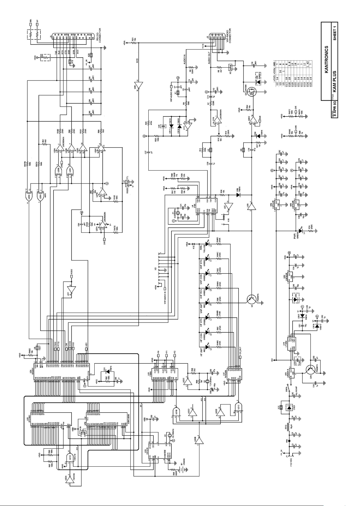
Page 93

 Loading...