

Kanto AVS2, AVS3, AVS SERIES, AVS1 User Manual
AVS SERIES
WALL MOUNT SHELVING SYSTEM
SYSTÈME DE RAYONNAGE DE MONTAGE MURALE
SISTEMA DE ESTANTERÍAS DE MONTAJE EN PARED
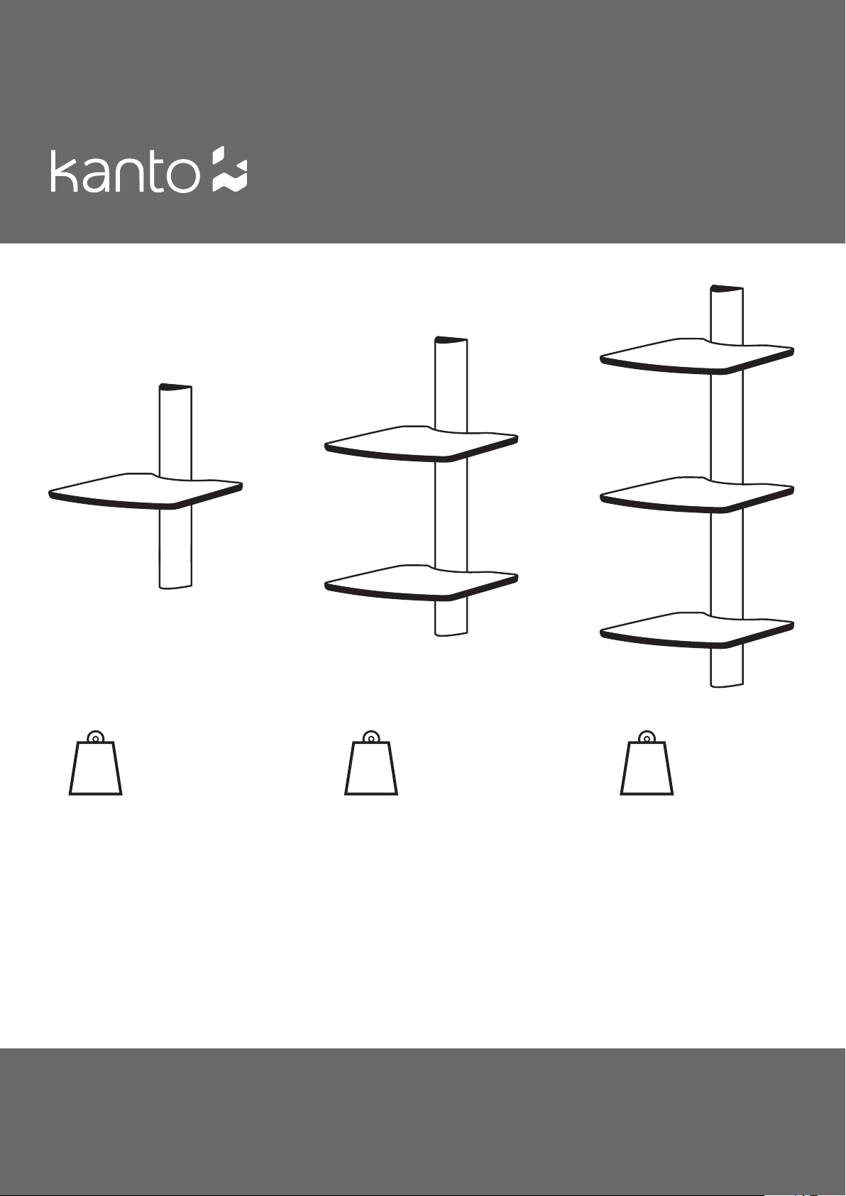
AVS1
30 lbs
(14 kg)
MANUEL DE L’UTILISATEUR
AVS2
45 lbs
(20 kg)
USER MANUAL
AVS3
60 lbs
(27 kg)
MANUAL DEL USUARIO
Table of Contents / Table des Matières / Tabla de Contenidos
English
Introduction .....................................................3
Supplied Parts & Hardware ..........................................4
Setup - Step 1 .................................................... 5
Setup - Step 2 .................................................... 6
Setup - Steps 3, 4 .................................................7
Setup - Step 5 .................................................... 8
Other Kanto Products / Warranty ......................................9
Français
Introduction .....................................................10
Matériel et les pièces fournies ....................................... 11
Installation – Étape 1 ..............................................12
Installation – Étape 2 ..............................................13
Installation – Étapes 3, 4 ...........................................14
Installation – Étape 5 ..............................................15
Autres produits Kanto / Garantíe .....................................16
Español
Introducción ..................................................... 17
Partes suministradas y materiales ....................................18
Preparación - Paso 1 .............................................. 19
Preparación - Paso 2 .............................................. 20
Preparación - Pasos 3, 4 ...........................................21
Preparación - Paso 5 .............................................. 22
Otros productos Kanto / Garantía ....................................23
support.kantoliving.com
888.848.2643
support@kantoliving.com
AVS1/ AVS2/ AVS3
WALL MOUNT SHELVING SYSTEM
Table of Contents
Introduction .............................3
Supplied Parts & Hardware..................4
Setup - Step 1............................5
Setup - Step 2............................6
Setup - Steps 3 to 4 .......................7
Setup - Step 5............................8
Other Kanto Products ......................9
Warranty ................................9
Introduction
Thank you for choosing a Kanto Living Wall Mount Shelving System. The installation instructions for the AVS1, AVS2 and
AVS3 are virtually identical, and you can break down your AVS2 or AVS3 into multiple shelving units, if preferred. The
shelves can be installed to a wood stud, into concrete, or into drywall. Maximum weights are indicated on the cover, and
the height of the shelves is easily adjustable during installation.
Read these instructions fully before installation of this mount. If you do not understand these directions, or have any
doubts about the safety of the installation, please consult a qualified installation contractor to install this mount.
Make sure there are no defective or missing parts. Do not use defective parts. If there is hardware missing, or if you
are uncertain whether the part is defective call Kanto directly at 1-888-848-2643 or support@kantoliving.com. Kanto
cannot be liable for property damage or injury caused by incorrect mounting, incorrect assembly, lifting or incorrect
use of this product.
This product should not be mounted on steel stud walls or cinder block walls. Consult a qualified installation contractor if you are unsure about the type of wall you may have.
See installation video online at:
www.kantoliving.com
Visit our Website for the most recent version of this manual
CAUTION
The maximum loading weight for AVS1 is 30 lbs (14 kg), for AVS2 is 45 lbs (20 kg), and for AVS3 is 60 lbs (27
kg). This shelving system is intended for use only within the maximum weight restrictions indicated. Use with products
heavier than the maximum weights indicated may result in instability causing possible injury.
CAUTION
The wall you plan to affix the Kanto shelving system to must be able to support more than 5 times the weight
of the shelves and AV components combined. Improper installation may cause damage to your AV components or
serious injury. This product should not be mounted to steel stud walls, cinder block or old concrete walls. Consult a
qualified installation contractor if you are unsure about the type of wall you may have.
English
3
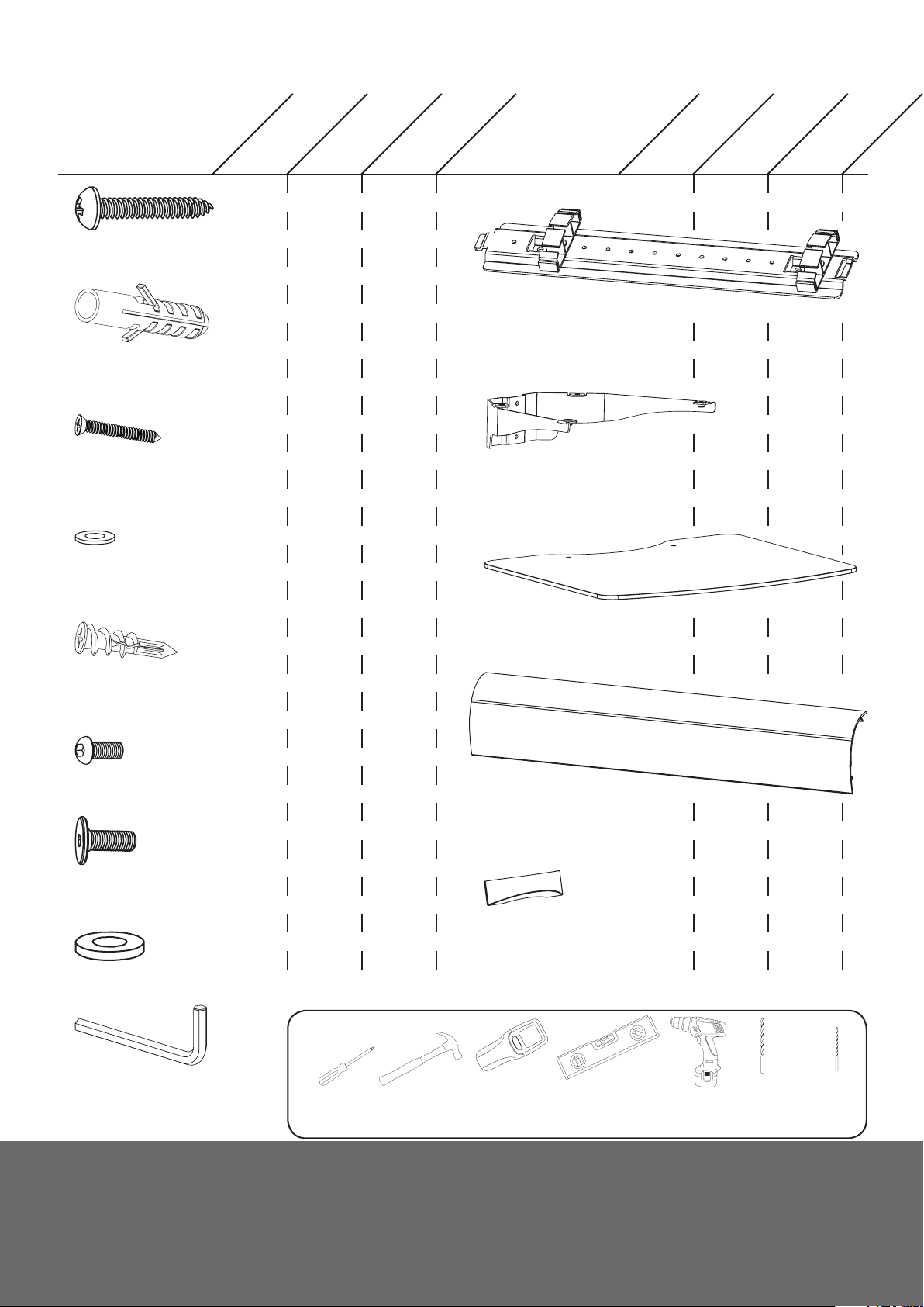
Supplied Parts and Hardware
x2
A: M6 x 50mm Screw
x2
B: Concrete Anchor
x2
C: #8 x 35mm Phillips Screw
x2
D: Washer
AVS1
x4
x4
x4
x4
AVS2
x6
x6
x6
x6
AVS3
I: Wall Plate
J: Shelf Support
x1
x1
AVS1
x2
x2
AVS2
x3
x3
AVS3
E: Drywall Anchor
F: M6 x 10mm Bolt
G: M6 x 15mm Bolt
H: Plastic Washer
I: Allen Key
x2
x2
x2
x2
x4
x4
x4
x4
x6
x6
x6
x6
Required Tools
Phillips
Screwdriver
Hammer
(for concrete
installs)
K: Glass Shelf
L: Cable Cover
M: End Cap
Stud Finder
Level
x1
x1
Drill
x2
x2
3/8”
Masonry
Bit
x3
x3
x6x2 x4
1/8”
Wood
Bit
4
English
Supporting your digital lifestyle
™
Step 1: Preparation
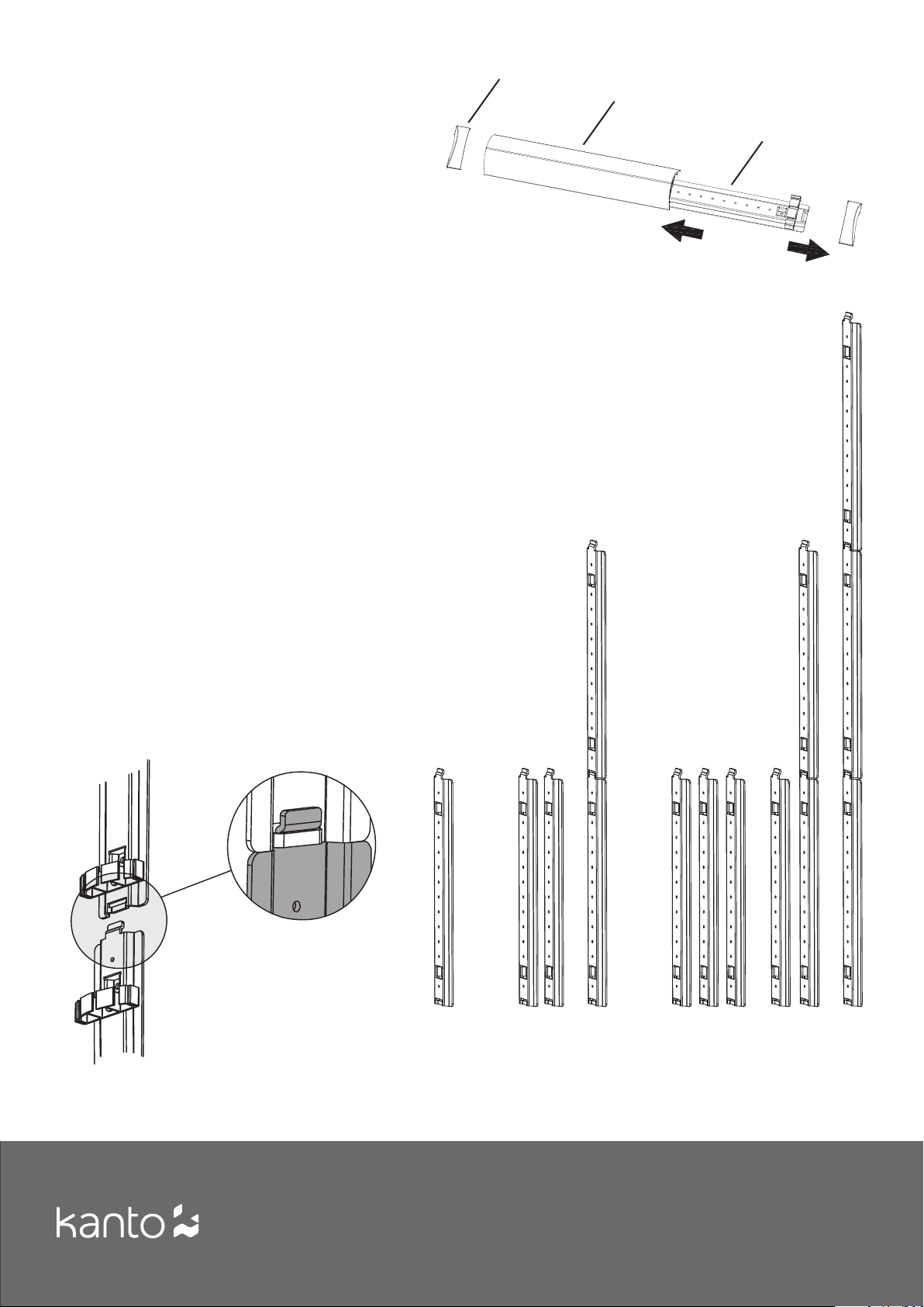
Step 1.1 Remove Cable Covers
The AVS Series Wall Mount Shelving System comes
pre-packaged from the factory with the cable
covers snapped in place on the wall plates’ (I) cable
management clips. Remove the Cable Covers (L)
and End Caps (M) by sliding them off of the cable
management clips (as shown in Diagram A), and set
them aside.
NOTE- The AVS3 is shipped with the cover snapped in
place on one of the three wall plates.
Step 1.2 Connecting Wall Plates
With the AVS2 and AVS3, you can connect wall plates
together by inserting the tab of one wall plate into the
slot on the other wall plate (as shown in Diagram B).
If you are connecting wall plates, mount the top wall
plate first, then insert the tab of the next wall plate from
the bottom and continue.
Step 1.3 Choose Layout
The AVS2 and AVS3 can be installed as a single
intreconnected shelving unit, or as two separate
shelving units. Consider how you want to interconnect
the wall plates to provide the ideal shelf configuration
for your installation.
M
L
I
Diagram A
All possible AVS wall plate configuration options are
shown in Diagram C.
Rear
View
AVS1
AVS2
separate
AVS2
linked
AVS3
separate
AVS3
single +
double
AVS3
triple
Diagram B Diagram C
English
5
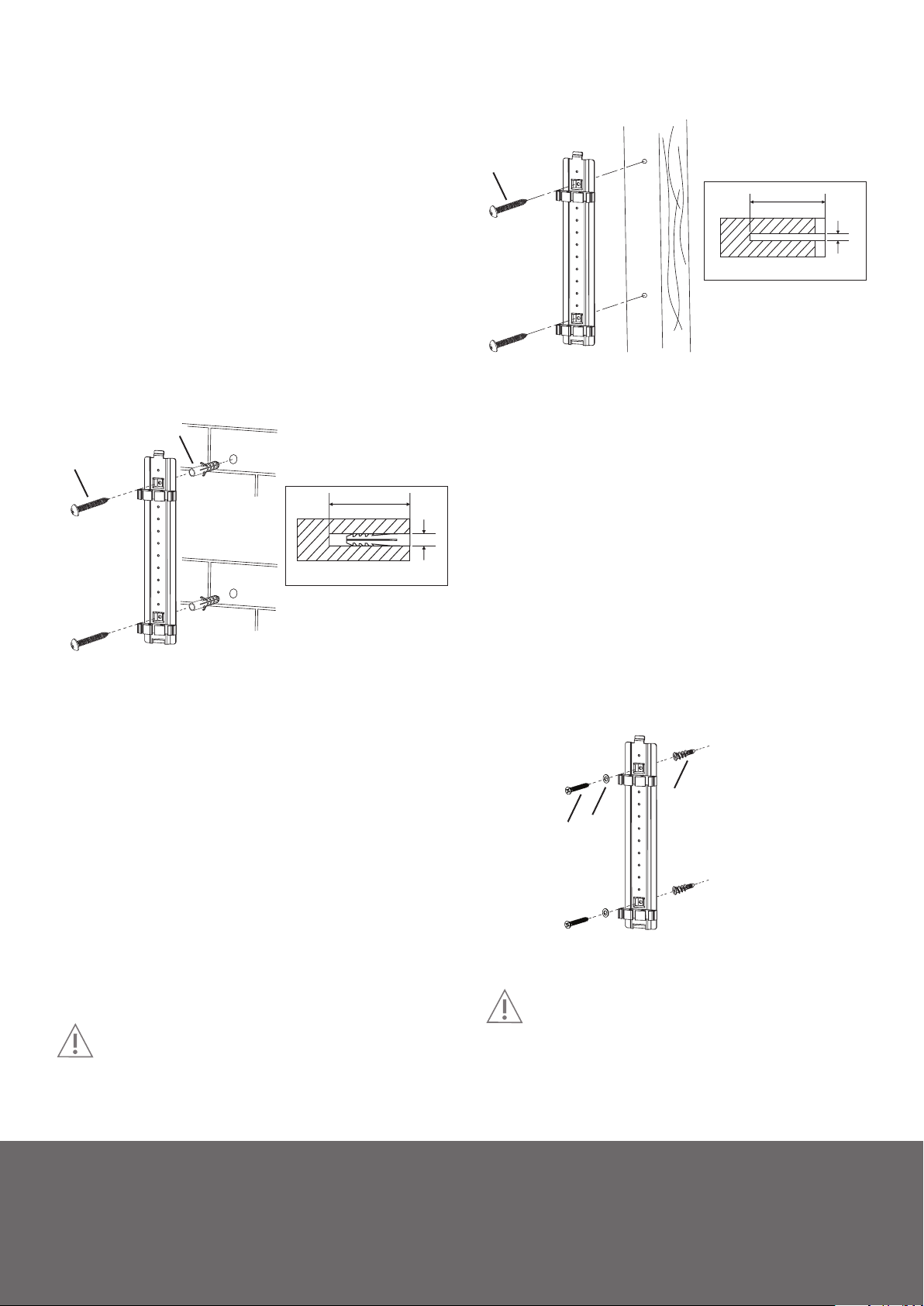
Step 2: Mount Wall Plate(s)
Wood Stud Wall
If possible, mount the wall plates to a wood stud. Use a
stud sensor to locate the stud, clearly marking the outer
edges of the stud.
Pre-drill the upper hole in the center of your stud, and
attach the wall plate temporarily to the wall using M6 x
50mm screw (A), as shown in Diagram D. Use a level to
ensure the wall plate is vertical, then mark the bottom
hole. Remove the wall plate and pre-drill the bottom
hole. Make sure the wall plate is flat against the wall
surface. Attach the wall plate using two M6 x 50mm
screws (A), taking care not to over-tighten.
Subsequent wall plates can be added by inserting tab,
checking vertical, marking, pre-drilling and attaching.
B
A
2” (50 m m)
3/8”
(10 mm )
A
2” (50 m m)
1/8”
(4 mm)
Diagram D
Brick or Concrete Wall
For brick or concrete installations, use a wall plate as
a template and mark two holes at your desired height.
Adjust the wall plate position to be clear of mortar joints.
Use a level to ensure the holes are vertical.
Pre-drill two holes, and insert a Concrete Anchor (B) into
each of the holes flush with the concrete wall surface and
not flush with the surface covering, such as drywall.
Attach the Wall Plate using two M6 x 50mm screws (A),
as shown in Diagram E. Make sure the Wall Plate is flat
against the wall surface. Do not over-tighten screws (A).
Diagram E
Drywall
The AVS series can be mounted to drywall. Use a wall
plate as a template and mark two holes at your desired
height. Use a level to ensure the holes are vertical.
Pre-drill two holes, and screw a Drywall Anchor (E) into
each of the holes flush with the drywall surface. Attach
the wall plate using two #8 x 35mm Phillips screws (C)
and washers (D), as shown in Diagram F. Take care not to
over-tighten.
Subsequent wall plates can be added by inserting tab,
checking vertical, marking, pre-drilling, screwing in
Drywall Anchor (E) and attaching.
CAUTION
Make sure the supporting surface will support
the load limits outlined in the Caution at bottom of
page two. Tighten screws until the Wall Plate is snug flat
against the wall. Do not over tighten screws (A) or (C).
Each screw should be screwed into a wood stud.
Subsequent wall plates can be added by inserting
tab, checking vertical, marking, pre-drilling, inserting
Concrete Anchors (B) and attaching.
E
D
C
Diagram F
CAUTION
Make sure the concrete or brick wall is at least
2.5” thick. Make sure the anchor is seated completely
flush with the concrete surface even if there is another
layer of material, such as drywall. If drywall is over 5/8”
thick custom lag bolts must be used. Concrete must be a
minimum of 2000psi in density.
6
English
Supporting your digital lifestyle
™
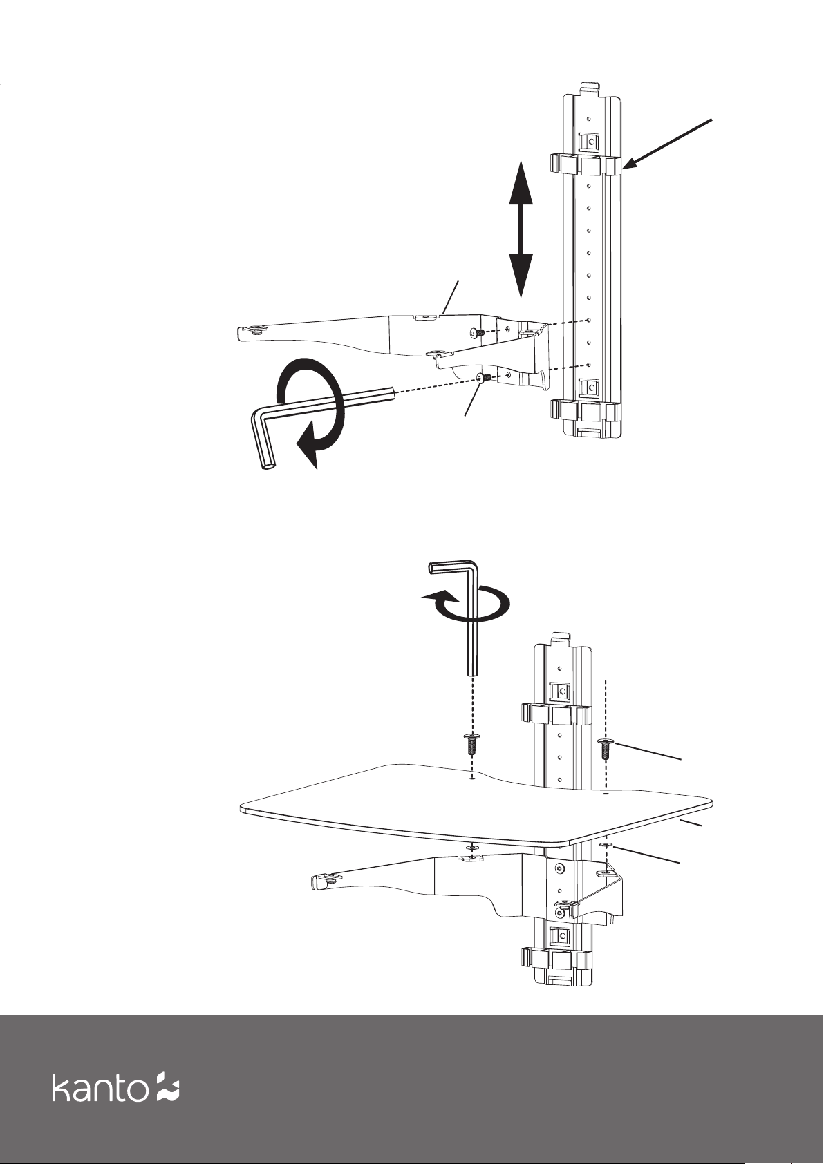
Step 3: Attach Shelf Supports
With the wall plate(s) secured to the wall, you can now attach
the shelf support(s) (J) at the desired height, using two M6
x 10mm bolts (F), as shown in Diagram G. Tighten using the
Allen Key (I).
If necessary, you can move the location of the cable
management clips by unscrewing the M6 x 10 mm bolt
holding the clip to the wall plate, repositioning the cable
management clip, and screwing the M6 x 10mm bolts. Tighten
using the Allen Key (I). The shelf system does not interfere
with the cable covers, so you can position the shelf supports
and cable management clips wherever you wish.
x2
3.2
Cable
Management
Clip
3.1
J
F
Diagram G
Step 4: Attach Shelves
With the shelf support(s) attached at the desired height,
you can now attach the glass shelf (or shelves) (K). Use two
M6 x 15mm bolts (G) and two plastic washers (H) for each
shelf, as shown in Diagram H.
G
K
H
Diagram H
English
7
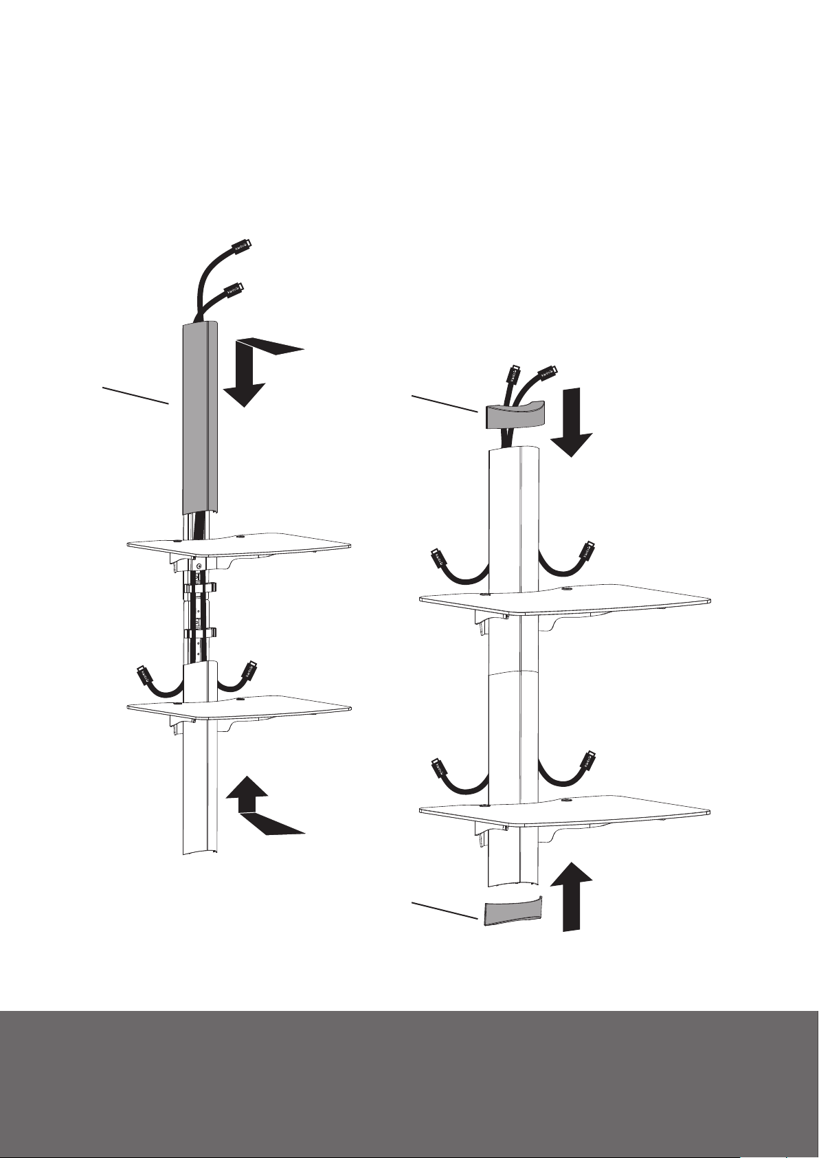
Step 5: Cable Management
Insert your cables into the cable management clips
provided on the wall plates, as shown in Diagram I. Route
cables through as many cable management clips as
required, and leave enough length to comfortably reach
your components.
Slide the cable covers (L) into position as shown, add the
end caps (M) and your installation is complete.
L
M
8
English
M
Diagram I
Supporting your digital lifestyle
™
 Loading...