


Installation Manual
Kantech Telephone Entry System
DN1769-1809


Kantech Telephone Entry System Installation Manual
Table of Contents
KANTECH WARRANTY TERMS ...................................................................................................... v
General Description ....................................................................................................................... 1
Pre-Installation Information................................................................................................................................................1
Copyright Information ........................................................................................................................................................1
Safety Instructions .............................................................................................................................................................1
Technical Support..............................................................................................................................................................2
Compliance Specifications.................................................................................................................................................3
Overview............................................................................................................................................................................5
Features ............................................................................................................................................................................6
Optional Accessories .........................................................................................................................................................7
1 - System Architecture......................................................................................................................................11
2 - Technical Specifications............................................................................................................................... 15
3 - Electrical Specifications ...............................................................................................................................16
4 - Installing the KTES ........................................................................................................................................17
4.1 Preparing to Install the KTES ......................................................................................................................................17
4.2 Installation ...................................................................................................................................................................17
5 - KTES Models, Options, Related Documentation and Miscellaneous Items............................................. 25
6 - Troubleshooting ............................................................................................................................................27
7 - Heartbeat Patterns.........................................................................................................................................28
8 - Hardware Default initialization .....................................................................................................................29
8.1 How to reset the Kantech Telephone Entry System for Factory Default .....................................................................29
9 - Maintenance Recommendations.................................................................................................................. 30
Appendix A - Installation Checklist ............................................................................................... 31
DN1769-1809
iii

iv
DN1769-1809

Kantech Telephone Entry System Installation Manual
KANTECH WARRANTY TERMS
For KANTECH Products Provided With or Without Components or Software
KANTECH Products purchased with or without Components and Software is copyrighted and is purchased under the following limited
warranty terms:
Sensomatic Electronics, LLC (“Kantech”) warrants the original purchaser that for a period of 2 years from the date of purchase, the product shall be free of
defects in materials and workmanship under normal use. During the warranty period, Kantech shall, at its option, repair or replace any defective product
upon return of the product to its factory, at no charge for labour and materials. Any replacement and/or repaired parts are warranted for the remainder
of the original warranty period or ninety (90) days, whichever is longer. The original purchaser must promptly notify Kantech in writing that there is
defect in material or workmanship, such written notice to be received in all events prior to expiration of the warranty period. There is absolutely no
warranty on software, and all software products are sold as a user license under the terms of the software license agreement included with the product.
The Customer assumes all responsibility for the proper selection, installation, operation and maintenance of any products purchased from KANTECH.
Custom products are only warranted to the extent that they do not function upon delivery. In such cases, KANTECH can replace or credit at its option.
International Warranty
The warranty for international customers is the same as for any customer within Canada and the United States, with the exception that Kantech shall not
be responsible for any customs fees, taxes, or VAT that may be due.
Warranty Procedure
To obtain service under this warranty, please return the item(s) in question to the point of purchase. All authorized distributors and dealers have a
warranty program. Anyone returning goods to Kantech must first obtain an authorization number. Kantech will not accept any shipment whatsoever for
which prior authorization has not been obtained.
Conditions to Void Warranty
This warranty applies only to defects in parts and workmanship relating to normal use. It does not cover any of the following, the occurrence of
which will void this warranty:
• damage incurred in shipping or handling;
• damage caused by disaster such as fire, flood, wind, earthquake or lightning;
• damage due to causes beyond the control of Kantech, such as excessive voltage, mechanical shock or water damage;
• damage caused by unauthorized attachment, alterations, modifications or foreign objects;
• damage caused by peripherals (unless such peripherals were supplied by Kantech.);
• defects caused by failure to provide a suitable installation environment for the products;
• damage caused by use of the products for purposes other than those for which it was designed;
• damage from improper maintenance; and
• damage arising out of any other abuse, mishandling or improper application of the products.
Items Not Covered by Warranty
In addition to the items which void the Warranty, the following items shall not be covered by Warranty: (i) freight cost to the repair centre; (ii) products
which are not identified with KANTECH's product label and lot number or serial number; (iii) products disassembled or repaired in such a manner as to
adversely affect performance or prevent adequate inspection or testing to verify any warranty claim. Access cards or tags returned for replacement
under warranty will be credited or replaced at KANTECH's option. Products not covered by this warranty, or otherwise out of warranty due to age, misuse,
or damage shall be evaluated, and a repair estimate shall be provided. No repair work will be performed until a valid purchase order is received from the
Customer and a Return Merchandise Authorization number (RMA) is issued by KANTECH’s Customer Service. Kantech’s liability for failure to repair the
product under this warranty after a reasonable number of attempts will be limited to a replacement of the product, as the exclusive remedy for breach of
warranty. Under no circumstances shall Kantech be liable for any special, incidental, or consequential damages based upon breach of warranty, breach of
contract, negligence, strict liability, or any other legal theory. Such damages include, but are not limited to, loss of profits, loss of the product or any
associated equipment, cost of capital, cost of substitute or replacement equipment, facilities or services, down time, purchaser’s time, the claims of third
parties, including customers, and injury to property. The laws of some jurisdictions limit or do not allow the disclaimer of consequential damages. If the
laws of such a jurisdiction apply to any claim by or against KANTECH, the limitations and disclaimers contained here shall be applicable to the greatest
extent permitted by law. Some states do not allow the exclusion or limitation of incidental or consequential damages, so that the above may not apply to
you.
Disclaimer of Warranties
This warranty contains the entire warranty and shall be in lieu of any and all other warranties, whether expressed or implied (including all implied
warranties of merchantability or fitness for a particular purpose) and of all other obligations or liabilities on the part of Kantech. Kantech neither assumes
responsibility for, nor authorizes any other person purporting to act on its behalf to modify or to change this warranty, nor to assume for it any other
warranty or liability concerning this product. This disclaimer of warranties and limited warranty are governed by the laws of the state of New York.
WARNING:
Kantech recommends that the entire system be completely tested on a regular basis. However, despite frequent testing, and due to, but not limited to,
criminal tampering or electrical disruption, it is possible for this product to fail to perform as expected.
DN1769-1809
v

Out of Warranty Repairs
Kantech will at its option repair or replace out-of-warranty products which are returned to its factory according to the following conditions. Anyone
returning goods to Kantech must first obtain an authorization number. Kantech will not accept any shipment whatsoever for which prior authorization
has not been obtained. Products which Kantech determines to be repairable will be repaired and returned. A set fee which Kantech has predetermined
and which may be revised from time to time will be charged for each unit repaired. Products which Kantech determines not to be repairable will be
replaced by the nearest equivalent product available at that time. The current market price of the replacement product will be charged for each
replacement unit.
WARNING - PLEASE READ CAREFULLY
Note to Installers
This warning contains vital information. As the only individual in contact with system users, it is your responsibility to bring each item in this warning to
the attention of the users of this system.
System Failures
This system has been carefully designed to be as effective as possible. There are circumstances, however, involving fire, burglary, or other types of
emergencies where it may not provide protection. Any access control system of any type may be compromised deliberately or may fail to operate as
expected for a variety of reasons. Some but not all of these reasons may be:
• Inadequate Installation
An access control system must be installed properly in order to provide adequate protection. Every installation should be evaluated by a security
professional to ensure that all access points and areas are covered. Locks and latches on windows and doors must be secure and operate as intended.
Windows, doors, walls, ceilings and other building materials must be of sufficient strength and construction to provide the level of protection expected.
A reevaluation must be done during and after any construction activity.
• Criminal Knowledge
This system contains security features which were known to be effective at the time of manufacture. It is possible for persons with criminal intent to
develop techniques which reduce the effectiveness of these features. It is important that an access control system be reviewed periodically to ensure
that its features remain effective and that it be updated or replaced if it is found that it does not provide the protection expected.
• Access by Intruders
Intruders may enter through an unprotected access point, circumvent a sensing device, evade detection by moving through an area of insufficient
coverage, disconnect a warning device, or interfere with or prevent the proper operation of the system.
• Power Failure
Control units, readers, exit detectors and many other security devices require an adequate power supply for proper operation. If a device operates from
batteries, it is possible for the batteries to fail. Even if the batteries have not failed, they must be charged, in good condition and installed correctly. If a
device operates only by AC power, any interruption, however brief, will render that device inoperative while it does not have power. Power interruptions
of any length are often accompanied by voltage fluctuations which may damage electronic equipment such as an access control system. After a power
interruption has occurred, immediately conduct a complete system test to ensure that the system operates as intended.
• Motion Detectors - Request to Exit
Motion detectors can only detect motion within the designated areas as shown in their respective installation instructions. Motion detectors do not
provide volumetric area protection. They have multiple beams of detection and motion can only be detected in unobstructed areas covered by these
beams. They cannot detect motion which occurs behind walls, ceilings, floor, closed doors, glass partitions, glass doors or windows. Any type of
tampering whether intentional or unintentional such as masking, painting, or spraying of any material on the lenses, mirrors, windows or any other part
of the detection system will impair its proper operation. Passive infrared motion detectors operate by sensing changes in temperature. However their
effectiveness can be reduced when the ambient temperature rises near or above body temperature or if there are intentional or unintentional sources of
heat in or near the detection area. Some of these heat sources could be heaters, radiators, stoves, barbeques, fireplaces, sunlight, steam vents, lighting
and so on.
• Component Failure
Although every effort has been made to make this system as reliable as possible, the system may fail to function as intended due to the failure of a
component.
• Inadequate Testing
Most problems that would prevent a system from operating as intended can be found by regular testing and maintenance. The complete system should
be tested weekly and immediately after a break-in, an attempted break-in, a fire, a storm, an earthquake, an accident, or any kind of construction activity
inside or outside the premises. The testing should include all sensing devices, keypads, consoles, alarm indicating devices and any other operational
devices that are part of the system.
vi
DN1769-1809

Kantech Telephone Entry System Installation Manual
General Description
Pre-Installation Information
To the Installer: If you are familiar with the installation, you can jump to section 4 - Installing the KTES or use the
Appendix A - Installation Checklist on page 31 of this manual.
Copyright Information
Copyright © 2018 Tyco International Ltd. and its Respective Companies. All Rights Reserved. All specifications
were current as of publication date and are subject to change without notice. Kantech and the Kantech logo are
trademarks of Tyco International Ltd. and its Respective Companies.
Safety Instructions
Important: NEVER INSTALL THE EQUIPMENT DURING A LIGHTNING STORM!
This equipment, Kantech Telephone Entry System, shall be installed and used within an environment that provides
the pollution degree max 2 and over voltages category II NON HAZARDOUS LOCATIONS, INDOOR and
OUTDOOR. The equipment is FIXED and PERMANENTLY CONNECTED and is designed to be installed by
Service Persons only; [service person is defined as a person having the appropriate technical training and
experience necessary to be aware of hazards to which that person may be exposed in performing a task and of
measures to minimize the risks to that person or other persons.] The equipment is installed in a metallic cabinet
that meets the applicable requirements for a FIRE ENCLOSURE.
1.The connection to the mains supply must be made as per the local authorities rules and regulations: In the UK
as per BS6701. An appropriate disconnect device must be provided as part of the building installation. Where it is
not possible to rely on the identification of the NEUTRAL in the AC MAINS SUPPLY, the disconnecting device must
disconnect both poles simultaneously (LINE and NEUTRAL).
• Be permanently connected, fail safe, with double or reinforced insulation between primary and secondary
circuits.
• The ground connection must be provided by the TERMINAL BLOCK at the PE (IEC 60417-5019 symbol)
marked connection. It is the installer’s responsibility to provide protection against a short circuit on the
input (bridge rectifier, C2, etc.).
• The system requires the integrity of the subscribed telephone line to be operational at all times. If the
telephone line is cut off, placed out of service, or shared with other interconnect telephone devices other
than the KTES, the unit will not be able to perform its function when required.
2.AVOID setting up the equipment near heaters, air conditioners, ventilators. DO NOT select a place that exposes
the KTES to vapors, chemicals or dust.
3.If during the installation a knockout on the cabinet is removed, it is the installer's responsibility to ensure that the
same degree of protection for the cabinet is provided by the use of bushings, fittings, adequate sealant, etc.
4.The metallic cabinet must be secured to the building structure before operation.
5.The ground connection must be as shown within the included diagram, or equivalent.
6.Internal wiring must be routed in a manner that prevents:
• Excessive strain on wire and on terminal connections;
• Loosening of terminal; connections;
• Damage of conductor insulation.
7.It is the end-user and/or installer's responsibility to ensure that the disposal of the used batteries is made according
to the waste recovery and recycling regulations applicable to the intended market.
8.There are no serviceable parts within the equipment; For any issues regarding the equipment please contact
your installer.
9.CAUTION: To reduce the risk of fire, use only AWG #26 or larger telecommunication line cord.
10.CAUTION: Risk of explosion if battery is replaced by an incorrect type. Dispose of used batteries according to the
instructions.
11. Sealant application is required on all mounting holes and removed knockouts. The draining holes must not be
blocked by any excess of sealant.
12.DISCONNECT POWER BEFORE SERVICING.
DN1769-1809
1

Technical Support
For technical assistance with the Kantech Telephone Entry System and other Kantech products, contact technical
support, Monday to Friday. To contact technical support, you can follow this link:
http://www.kantech.com/Support/Contact_Technical_Support_Advanced.aspx
See the following table for the technical support phone numbers and email address.
Country/Region Phone Numbers Support Hours Email
North America Toll Free +1 888 222 1560 (GMT -05:00)
US and Canada Direct: +1 450 444 2030 8:00 to 20:00 access-support@jci.com
Latin America (GMT -03:00)
Argentina, Buenos
Aires
Brazil, Sao Paolo Direct +5511 3181 7377
Chile, Santiago Direct +562 3210 9662
Colombia, Bogota Direct +571 344 1422
Colombia, Cali Direct +572 891 2476
Colombia, Medellin Direct +574 204 0519
Costa Rica, National Direct +506 4000 1655
Dominican Republic,
Santo Domingo
El Salvador, San Sal-
vador
Guatemala, Guate-
mala City
Mexico, Mexico City Direct +5255 8526 1801
Panama, Panama City Direct +507 836 6265
Peru, Lima Direct +51 1642 9707
Venezuela, Caracas Direct +58 212 720 2340
Asia Direct +8621 6023 0650
China Direct +400 671 1528
India Direct +1800 1082 008
Australia Direct +02 9684 3980
Direct: +5411 5199 3104
Direct +1829 235 3047
Direct +503 2136 8703
Direct +502 2268 1206
Asia Toll free +800 CALL TYCO / +800 2255 8926 (GMT +08:00)
EMEA Toll Free +800 CALL TYCO / +800 2255 8926 (GMT +01:00)
8:00 to 20:00 access-support@jci.com
9:00 to 17:00 access-support@jci.com
Bahrain Direct +800 04127
Belgium Direct +0800 76 452
Denmark Direct +45 4494 9001
France Direct +0800 90 79 72
Germany Direct +0800 1806 757
Greece Direct +00 800 3122 9453
Ireland Direct +1800 94 35 70
Italy Direct +39 0230 510 112
2
8:00 to 18:00 access-support@jci.com
DN1769-1809

Kantech Telephone Entry System Installation Manual
Country/Region Phone Numbers Support Hours Email
Nordic countries Direct +45 4494 9001 8:00 to 18:00 access-support@jci.com
Russia Direct +81 0800 2052 1031
South Africa Direct +2721 100 3882
Spain Direct +900 99 31 61
Tur key Direct +00800 3192 3007
United Arab Emirates Direct +800 0310 7123
United Kingdom Direct +44 330 777 1300
DN1769-1809
3

Compliance Specifications
FCC & IC Compliance
• This device complies with FCC 2000 Part 15 Class B (Radiated Emissions, Residential, USA). Operation
is subject to the following two conditions: (1) this device may not cause harmful interference, and (2) this
device must accept any interference received including interference that may cause undesired operation.
This class B digital apparatus meets all requirements of the Canadian Interference Causing Equipment
Regulations. The Kantech Telephone Entry System is also compliant with EN55022:1998, amendment
1:1995, Class B and CISPR 22.
• TIA968 (FCC part 68) Direct Connection to the PSTN (Public Switched Telephone Network) USA.
• FCC Registration Number: ACTA US: V85OT01BKTES125 REN: 01B
• DOC - CANADA: The Canadian Department of Communications label identifies certified equipment. This
certification means that the equipment meets certain telecommunications network protective, operational,
and safety requirements. The Department does not guarantee the equipment will operate to the users
satisfaction.
-Before installing this equipment, users should ensure that it is permissible to be connected to the facilities
of the local telecommunications company. The equipment must also be installed using an acceptable
means of connection. The customer should be aware that compliance with the above conditions may not
prevent degradation of service in some situations.
-Repairs to certified equipment should be made by an authorized Canadian maintenance facility
designated by the supplier. Any repairs or alterations made by the user to this equipment, or equipment
malfunctions, may give the telecommunications company cause to request the user to disconnect the
equipment.
-Users should ensure, for their own protection, that the electrical ground connections of the power utility,
telephone lines, and internal metallic water pipe system, if present, are connected together. This
precaution may be particularly important in rural areas.
-CAUTION: Users should not attempt to make such connections themselves, but should contact the
appropriate electric inspection authority, or electrician, as appropriate.
-In addition, the Kantech Telephone Entry System complies with the CS-03 (Direct Connection to the Public
Switched Telephone Network, Canada).
-DOC registration Number: IC: 5690B-KTES125
CE & CB Scheme Compliance
• EN50133-1 Alarm Systems – Access control systems for use in security applications, Europe
• EN55022 Radiated Emissions, Europe
• EN60950: Information technology equipment, safety
• EN61000-6-1: Electromagnetic Compatibility (EMC) - Generic Standards - Immunity for residential,
commercial and light-industrial environments
• EN61000-6-2: Electromagnetic Compatibility (EMC) - Generic Standards - Immunity for industrial
environments
• ETSI ES 203 021 Harmonized basic attachment requirements for Terminals for connection to analog interfaces
of the Telephone Networks, Europe
Australia, New Zealand
• Australia: The AS/ACIF 5002 Direct Connection to the Public Switched Telephone Network
• New Zealand: The PTC200 standard which is described as the following: Direct Connection to the Public
Switched Telephone Network, New Zealand
• CISPR 22: Information technology equipment - Radio disturbance characteristics - Limits and methods of
measurement
• The ferrite installation is mandatory, see Connecting the Telephone Line with the Ferrite (KTES-AUS
Model for Australia and New Zealand only) on page 24.
4
DN1769-1809

Kantech Telephone Entry System Installation Manual
Australia, New Zealand (continued)
GENERAL WARNING: The grant of a telepermit for any item of terminal equipment indicates only that Telecom
has accepted that the item complies with minimum conditions for connection to its network. It indicates no
endorsement of the product by Telecom, nor does it provide any sort of warranty. Above all, it provides no
assurance that any item will work correctly in all respects with another item of Telepermitted equipment of a
different make or model, nor does it imply that any product is compatible with all of Telecom's network services.
IMPORTANT NOTICE: Under power failure conditions, the KTES may not operate. Please ensure that a
separate telephone, not dependent on local power, is available for emergency use.
This equipment shall not be set up to make automatic calls to the Telecom "111" Emergency Service.
UL Compliance for the KTES-US and the KTES-CDN Models only
The Kantech Telephone Entry System (KTES) complies with the UL 294 which is described by the following: UL
Standard for Access Control Equipment, USA. The KTES enables users to grant access to the building, to their
visitors, via their own telephone line or cellular telephone. The KTES also supports basic schedule operations for
the postal lock supervision and automatic relay activation.
• The KTES can be connected to the PC via IP or RS-485 or internal PTSN to the phone line, these are all
supplementary. The KTES must be connected to one of the compatible controllers (KT-300 or KT-400).
• Use only a UL listed transformer available through Kantech distributors or dealers, please refer to the
Technical Support contact information to obtain the specific transformer, see page 2.
• Kantech part number TR1640P/UL (manufacturer part number Codex model SEP-1640U)
• Kantech part number TR1640P/CSA (manufacturer part number Codex model SEP/G-1640)
• For UL 294:
• Only models KTES-US (for installation in the USA) and KTES-CDN (for installation in Canada) are UL
listed.
• If the KTES door lock output is used in fail-secure mode, a listed panic hardware device shall be used
to allow emergency exit from the protected area.
• Electrical specifications, refer to Table 1 on page 18 and Table 2 on page 19.
• For class 1 installation, the optional camera need to be installed.
• Each KTES will be battery backed up with a KT-BATT-12, 12V/7Ah battery.
• The optional accessories allowed in a UL installation are:
• Heater kit (part number KTES-HEAT)
• Postal lock (part number KTES-POSTAL)
• Color camera (part number KTES-CAM-N)
• The KTES is an access control accessory.
• Humidity test conducted at 90%.
• Compatible card readers are: P225, P325, P600 and Polaris.
• The KTES has an on-board capability of monitoring 4 input points. Each onboard input is supervised with
or without end-of-line resistors (5.6K ohm). The maximum distance of one line is 600 m (2,000 ft) with
AWG #22 in a single or double EOL configuration.
UL 294 Performance Levels
Destructive
Attack
KTES-US Level I Level I Level IV Level IV
KTES-CDN Level I Level I Level IV Level IV
KTES-OEM Level I Level I Level IV Level IV
Standby power achieved when 12 VDC, 7 Ah battery is used.
Line Security Endurance
Standby
Power
RoHS (Restriction on Hazardous Substances)
This standard restricts the use of the following substances: Lead, cadmium, mercury, chromium IV,
polybrominated biphenyl (PBB), and polybrominated diphenyl ether (PBDE) in electrical and electronic equipment
by no later than July 1, 2006.
DN1769-1809
5

WEEE (Waste Electrical and Electronic Equipment)
This regulation is used for Waste Electrical and Electronic Equipment, and addresses the disposal and the
environmental handling of these products.
6
DN1769-1809
Overview
The Kantech Telephone Entry System enables users to grant access to the building, to their visitors, via their own
telephone line or cellular telephone. This telephone line can also serve, via an integrated modem, as a
programming link and/or a monitoring link. Programmed alarms and troubles can be reported to a pager. The
KTES also supports basic schedule operations for the postal lock supervision, automatic door unlock, automatic
relay activation, pager and dialup reporting.
The KTES is designed to be a stand-alone unit as well as a part of a complete access control system such as
EntraPass from Kantech. The KTES can be connected to a PC via IP or RS-485 or internal PSTN to the phone
line. It can communicate with EntraPass through a Corporate gateway for programming and monitoring. The
KTES installation can also include Kantech controllers (KT-100, KT-300 and KT-400) as well as any controller that
supports a Wiegand interface port.
This manual will describe the installation procedures required to install and power up the KTES. For the
configuration of the KTES, refer to the KTES Programming Manual, DN1770.
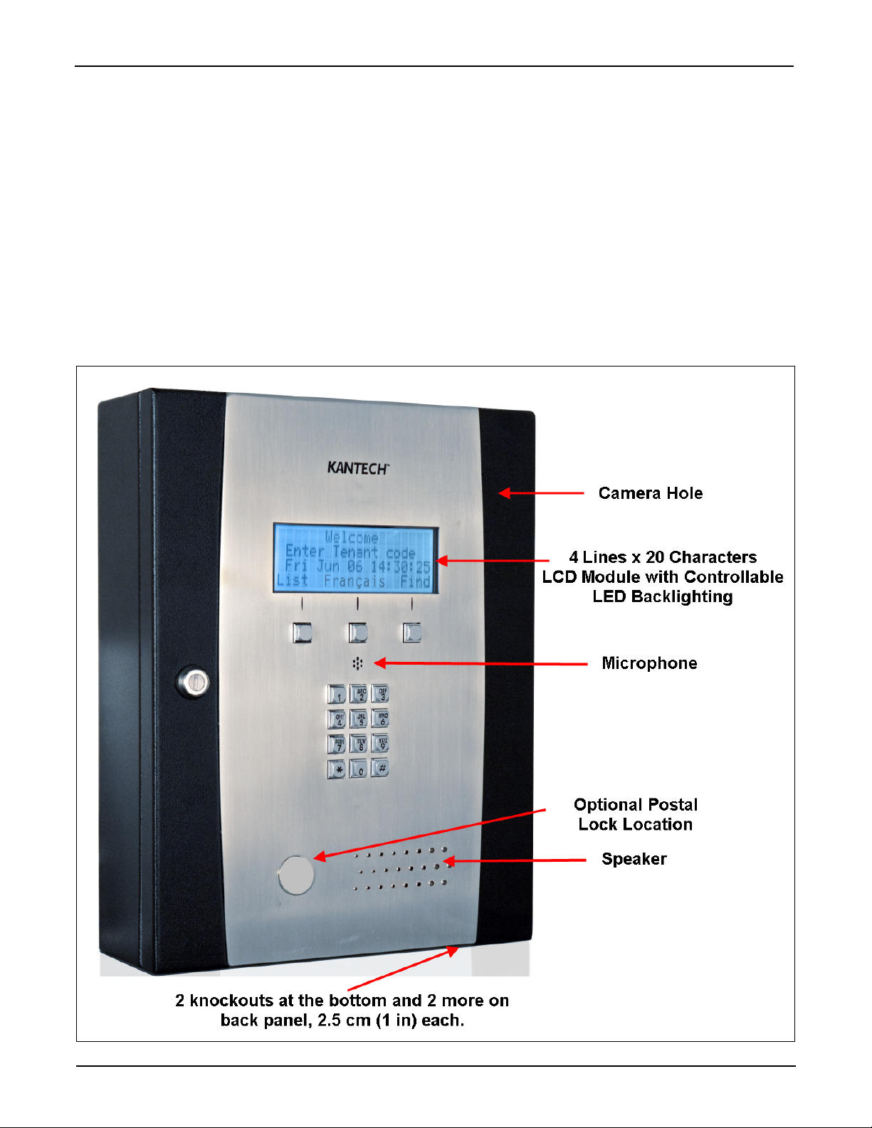
Figure 1: Front Panel Description
Kantech Telephone Entry System Installation Manual
DN1769-1809
7

Features
Compatible with any Access Controller Supporting a Wiegand Interface Port
• Any access controller with Wiegand reader port(s)
• Kantech KT-100, KT-300 and KT-400 controllers
Note: When the KTES is connected to a controller using the Wiegand interface, the control of the attached lock is
managed by the controller. This means the door locking device will be connected to the access controller and
not the KTES.
Compatible with all EntraPass Special, Corporate and Global Editions
The Kantech Telephone Entry System is compatible with all EntraPass Editions v4.02 and higher:
• EntraPass Special Edition
• EntraPass Corporate Edition with a Corporate Gateway
• EntraPass Global Edition with a Corporate Gateway
Multiple Configuration Options
• Visual User Interface (VUI): The KTES can be configured locally with the VUI, refer to the Programming
Manual, DN1770 for details concerning the VUI.
• EntraPass: The KTES can be configured and monitored through the EntraPass system, refer to the
corresponding EntraPass Reference Manual, for additional details.
Communication Ports
• 1 10/100Base-T Ethernet for network connection with the EntraPass Gateway
• 1 (TIP and RING) terminal block for phone line connections and for multiple KTES sharing the same
telephone line
• 1 RS-485 (COM1) for RS-485 communication with the EntraPass Gateway
Inputs
There are four (4) onboard inputs on the KTES. They are configurable with EOL (End-of-Line) resistor, without
EOL resistor, or with double EOL resistors. Respective alarm response timers are also programmable. By default,
Input 1 is assigned to the door contact and Input 2 is assigned to the postal lock. Each input can be individually
configured for one of the following applications:
• Door Contact
• Postal Lock
• Rex (Request to Exit) Device
• General Supervised Input
DC Powered Lock Output
There is one (1) onboard DC powered lock output and it is supervised.
Relay Outputs
There are three (3) onboard relay controlled outputs. The locking function can also be performed by any onboard
relay configured for lock output functionality.
Reader Interfaces
There are two (2) onboard reader interfaces. They can be programmed for one (1) Wiegand input port and one (1)
Wiegand output port.
Automatic Port Detection
The KTES can automatically detect the site communication RS-485 speed set by EntraPass as well as the
communication port which can be IP (ETHERNET #1), RS-485 (COM1) or Dialup modem.
Upgradable Firmware
The firmware program can be downloaded from any EntraPass workstation to the KTES. The firmware program,
stored in the KTES flash memory, is upgraded without having to change any parts.
8
DN1769-1809

Kantech Telephone Entry System Installation Manual
Trouble and Reporting
The KTES constantly supervises ac power and battery condition and reports “AC Lost”, “Normal Battery”, “Low
Battery”, or “No Battery”, status to the EntraPass system. Power outputs are supervised and electronically
protected against circuits surges. The locking device is also supervised for short to common and open circuit.
Event Buffer
The event buffer can hold up to 4000 events.
Visual Status Indicators (LEDs)
The KTES has multiple status indicators such as for troubleshooting, network activity, power status and outputs
activity. See Figure 8: for their locations.
• HEARTBEAT (BLUE): This LED indicates the working status of the KTES. Refer to Table 6 for a
description of the heartbeat patterns.
• COM1 RX, COM1 TX (YELLOW): The RS-485 port LEDs are transmit/receive activity indicators.
• COM2 RX and COM2 TX (YELLOW): For future use.
• OFF-HOOK (RED): This LED turns ON when the KTES is either dialing or answering a call.
• LOCK (RED): This LED turns ON when the lock output is activated.
• RELAY1, RELAY2 and RELAY3 (RED): Each relay output has an indicator which turns ON each time the
corresponding relay is activated.
• AC POWER and DC POWER (GREEN): These LEDs are on when AC and DC power are present.
• TXRX (YELLOW): This LED is OFF when there is no Ethernet network or the cable is disconnected;
FLASHING when there is an Ethernet cable and network activity; and ON when the network is present.
• 100 (GREEN): This LED is ON when the KTES is connected to a 100 Base-T Ethernet network.
Optional Accessories
The KTES can be mounted indoor or outdoor directly on the wall (surface mount) or recessed (flush mount). The
surface mount is described 4 - Installing the KTES. The following figures describes the options available with the
KTES. Each option has its own install sheet included.
DN1769-1809
9

Figure 2: KTES Flush Mounted with Box and Trim Ring
Matching Paper Directory
The KTES itself does not support a paper directory but has an optional matching enclosure designed just for that
purpose. This illuminated enclosure supports the letter format 216 x 279 mm (8.5 x 11 in) and A4 format 210 x
297 mm (8.3 x 11.7 in).
10
DN1769-1809

Figure 3: Paper Index Flush Mounted
Kantech Telephone Entry System Installation Manual
Camera
The KTES offers the possibility to install a color camera in the back of the front door.
Figure 4: Camera Position in Back of Front Door
DN1769-1809
11

Postal Lock
This option fits in the product enclosure. Its role is to allow postal service personnel access to the building. For
added security purpose its usage may be limited by a schedule.
Figure 5: Postal Lock Mounting Location
12
DN1769-1809

Kantech Telephone Entry System Installation Manual
Goose Neck
The KTES can be mounted on a goose neck stand.
Figure 6: Goose Neck Mounting Plate with Gaskets (Goose Neck not Included)
DN1769-1809
13

1 - System Architecture
PSTN
Dial-up
Connection
Stand-Alone with Reader
Kantech Telephone
Entry System (KTES)
EntraPass Software
(Special, Corporate & Global Editions
with Corporate Gateway)
LAN
Internet
Ethernet
Connections
(Optional)
(Optional)
RS-485
Wiegand
KTES
Door
Controller
Integrated with Access Control System
KTES
Stand-Alone over IP
with Reader
Pass-Through
RS-485
Integrated with Access Control System
over a Local Area Network (LAN)
KTES
Dial-Up
Connection
(Optional)
RS-485 Link
The KTES can be configured and monitored through various means:
• Locally with the Visual User Interface (VUI).
• Remotely with EntraPass over an Ethernet network.
• Remotely with EntraPass over RS-485.
• Remotely with EntraPass over the telephone line with a dialup modem. The KTES is compatible with the
US Robotics V.92 external modem.
Figure 7: KTES Configurations with EntraPass
Note: For the UL 294 Compliance, the KTES-US and KTES-CDN models must be integrated with an access control system
over a Wiegand connection.
14
DN1769-1809

Figure 8: PCB view of main board
Kantech Telephone Entry System Installation Manual
DN1769-1809
15
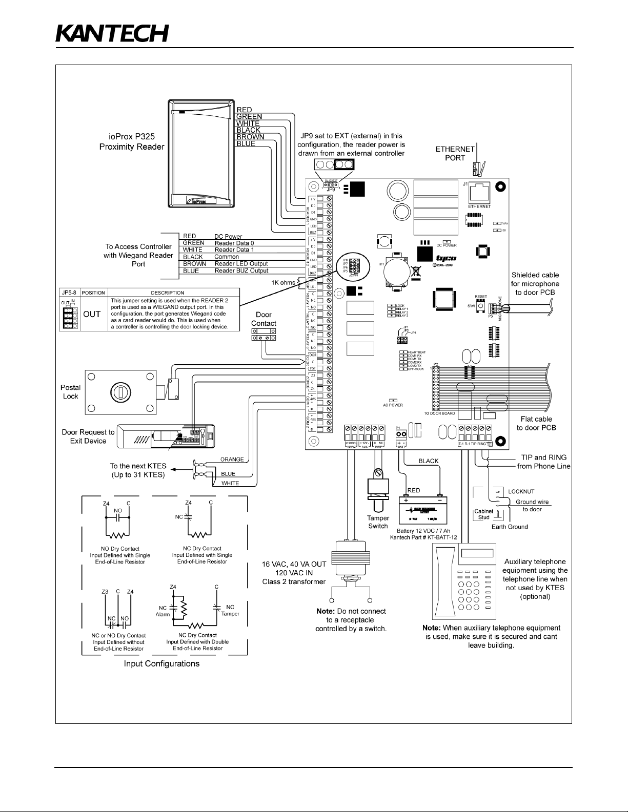
Figure 9: KTES Wiring Example with an External Controller - UL Compliant (North America)
16
DN1769-1809

Kantech Telephone Entry System Installation Manual
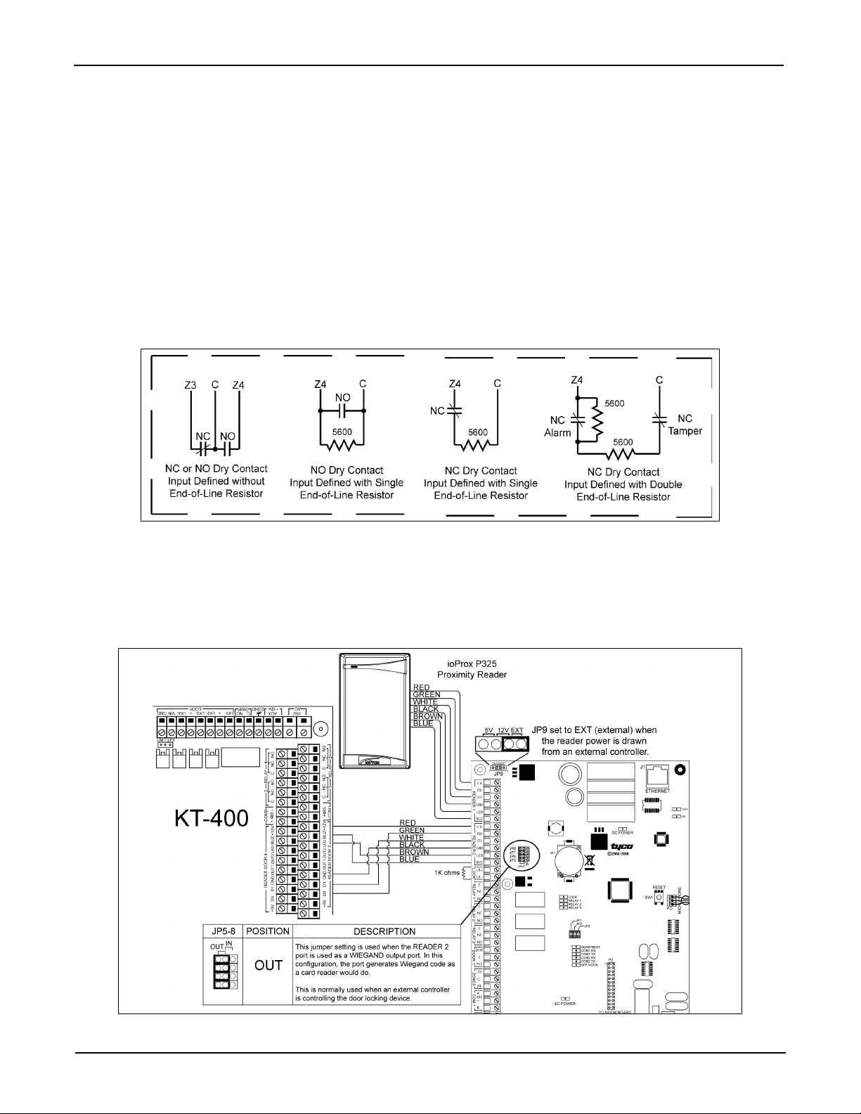
Figure 10: KTES Wiring Example with Reader (Stand Alone Application) - North America
DN1769-1809
17

2 - Technical Specifications
Table 1: Technical Specifications
Specification Description
AC Power Input (UL) 16.5 VAC, 40 VA, 1.9 Amps class 2 transformer, see Table 3 on page 28 for the part
numbers
DC Power Input (CE) 19 VDC, 3.15 Amps, see Table 3 on page 28 for the part numbers
DC Auxiliary Output 11.2 to 13.75 VDC, 450 mA
Lock Output 11.2 to 13.75 VDC, 650 mA
Relay Controlled Outputs • 3 Form C Relay controlled outputs
• 30 VDC, 3 Amps max each, or
• 24 VAC, 3 Amps max each
Reader Power Outputs
(JP9)
Auxiliary Reader Outputs 2 outputs per reader (LED and BUZ), 25 mA max. each, open collector outputs
Reader types Wiegand interface
Monitored Points
(Zone Inputs)
Points maximum wiring AWG #22 - 600 m (2,000 ft.)
Weight (UL Listed) 7.0 kg (15.4 lb)
Weight (CE Compliant) 7.0 kg (15.4 lb)
Visual User Interface (VUI)
Characteristics
Operating Temperatures Without heater kit: -10°C to 55°C (14°F to 131°F)
Humidity Level Indoor and outdoor: 0 to 90%
Storage Conditions Temperature: -40°C to 70°C (-40°F to 158°F)
Multiple KTES Cabling Telephone Line: 305 m (1,000 ft.) maximum
3 options with jumpers (JP9):
• 5 VDC, 175 mA, or
• 12 VDC, 175 mA, or
• from external controller
• 4 monitored points (Z1 to Z4), NO/NC, with or without EOL resistor
• 1 fixed-function tamper switch input
4 lines x 20 Characters LCD module with controllable LED backlighting.
The text on the 4th line cant be edited, but can be changed with the navigation buttons.
With heater kit: -40°C to 55°C (-40°F to 131°F)
RS-485 Bus: 1219 m (4,000 ft.) maximum
Ethernet network: 91 m (300 ft.) maximum
KTES Dimensions
(Surface Mount)
Communication ports 10/100 Base-T Ethernet Port (RJ-45 connector)
Communication speed • Ethernet: 10/100 Base-T
Flush Mount Box 30.33 cm (12 in.) Wide, 38.42 cm (15 1/8 in.) High, 7.15 cm (2 7/8 in.) Deep
Paper Index Flush Mount 29.21 cm (11 1/2 in.) Wide, 37.46 cm (14 3/4 in.) High, 2.82 cm (1 1/8 in.) Deep
18
29.21 cm (11 1/2 in.) Wide x 37.46 cm (14 3/4 in.) High x 9.91 cm (3.9 in.) Deep
1 x RS-485 (COM1)
Global Data Access Arrangement (DAA) interface for the telephone line
• RS-485: from 1200 to 115,200 Baud (automatic detection)
• Dialup Modem: Up to 2400 Baud
DN1769-1809

Kantech Telephone Entry System Installation Manual
Table 1: Technical Specifications
Specification Description
Paper Index Surface Mount 29.21 cm (11 1/2 in.) Wide, 37.46 cm (14 3/4 in.) High, 9.93 cm (4 in.) Deep
Paper Index Black Trim
Ring
Goose Neck Mounting
Plate
35.72 cm (14 in.) Wide, 44.13 cm (17 3/8 in.) High, 0.92 cm (3/8 in.) Deep
25.30 cm (10 in.) Wide, 36.50 cm (14 3/8 in.) High, 3.30cm (1 1/4 in.) Deep
3 - Electrical Specifications
Table 2: Electrical Specifications
AUXILIARY OUTPUTS MAXIMUM CURRENT COMBINED MAXIMUM
LED for each door reader 25 mA (each)
Buzzer (BUZ) for each door reader 25 mA (each)
OUTPUTS MAXIMUM CURRENT
1 for Auxiliary Power (11.2 to 13.75 VDC) 450 mA
2 for Controlled Readers (11.2 to 13.75 VDC) 175 mA
2 for Controlled Readers (5 VDC) 175 mA
1 for Lock Output (11.2 to 13.75 VDC) 650 mA
CURRENT
1.1 Amps
DN1769-1809
19

4 - Installing the KTES
Important: Make sure that the local telephone company has been notified that you will be installing communication
equipment.
4.1 Preparing to Install the KTES
A visual inspection should be made when unpacking the KTES. Any missing item/part or damaged component
should be reported immediately.
Stay away from electrical or communication devices
The KTES has been designed to be mounted indoor or outdoor. The cabinet is large enough to accommodate the
backup battery and the necessary wiring connections for most applications. Four (4) EMT (Electrical Metallic
Tubing) conduit knockouts (1.9 cm (0.75 in)) are provided. The location should be easily accessible for servicing
the equipment. The KTES must be located at a minimum distance of 2 m (6 ft) from any high voltage equipment or
wiring and from electrical equipment susceptible of generating electrical interference and at a minimum of 8 m (25
ft) from any transmitting equipment.
4.2 Installation
STEP 1: Unpacking the KTES
Check that the following parts are in your KTES package when you unpack it:
• Kantech Telephone Entry System (KTES)
• EntraPass software CD-ROM, version 4.02 or higher
• Installation Manual, English and French version
• Programming Manual, English and French version
Any missing item/part or damaged component should be reported immediately.
Note 1: The 12 VDC backup battery and the ground clamp are not included.
Note 2: Make sure you have adequate sealant (not included).
STEP 2: Applying Sealant on the Back of the
KTES
Sealant must be applied on each of the four mounting holes
when the KTES is installed outside in order to avoid water
infiltration. Also, apply sealant around any knockout that will
be removed.
Important: Be careful not to apply sealant on the four (4)
draining holes at the bottom of the KTES.
20
DN1769-1809

Figure 11: Surface Mount Installation
Kantech Telephone Entry System Installation Manual
STEP 3: Mounting
It is recommended that you mount the KTES so that the
bottom of the enclosure is not higher than 117 cm (46 in.)
from the floor. If you install it in a location where there are
extremely low temperatures, the outdoor installation might
require an optional heater kit in order to meet the
environmental conditions.
Caution: Make sure the area stays clear of any objects
below the KTES that could interfere with its daily use.
DN1769-1809
21
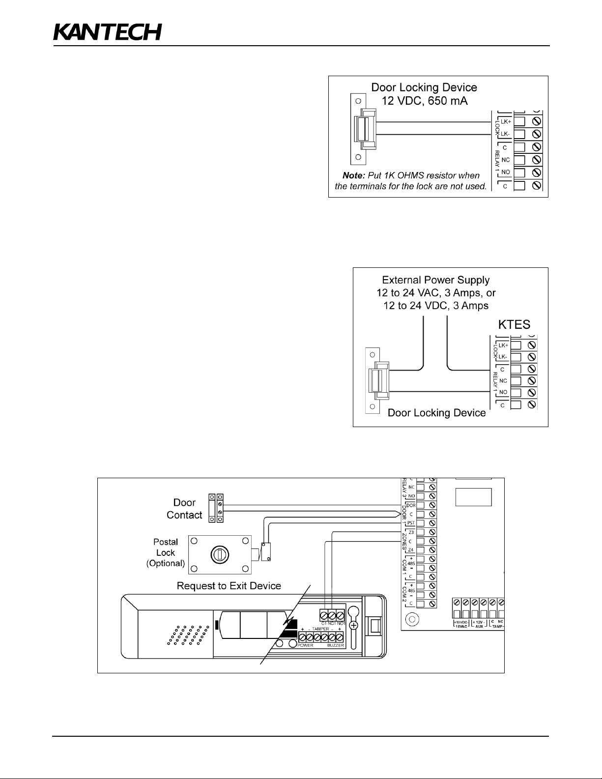
STEP 4: Connecting the Door Locking Device (DC Powered)
Connecting the Door Lock Device to LK+ and
LK-
Check for Local “magnetic lock” Regulations
The door locking device output is controlled according to
the end-user programmed parameters for allowing
access to or unlocking doors according to schedules and
access levels. The door locking device output can
operate DC powered locking devices such as an
electromechanical strike and can be configured to
operate fail-safe or fail-secure (normal or reverse action).
Note: Use 1 K ohm EOL (End-of-Line resistor) between LK+ and LK- terminals if not used.
STEP 5: Connecting the Door Lock Device with an External Power Supply
Use one of the three relay terminals available to connect the
door locking device and the external power supply.
STEP 6: Hooking Up Inputs
Connect Devices to Inputs 1 to 4
Note: Onboard inputs can be defined with: none, single or double EOL (End-of-Line) resistor(s) according to your
settings with the VUI or with EntraPass.
22
DN1769-1809
Kantech Telephone Entry System Installation Manual
Resistors for all Inputs 5.6K Ohms (EOL or DEOL) (Optional)
The KTES has an on-board capability of monitoring 4 input points. Each onboard input is supervised with or
without end-of-line resistors (5.6K ohm). The maximum distance of one line is 600 m (2,000 ft) with AWG #22.
Inputs 1-2 are automatically assigned. The door contact is assigned to input 1 and the postal lock is assigned for
input 2. There is no obligation to follow these rules but this standard convention facilitates servicing.
DRY (without EOL resistor): In a simple NC dry contact configuration, the secure state is given when a short is
detected. The alarm state is given when the input is open. If the alarm switch is programmed as NO device, the
alarm state will be given when the input is shorted.
EOL (with EOL resistor): The secure state is given when a single resistor is detected. The alarm state is given
when the input is open or short.
DEOL (Double EOL Resistor): For NC device only, in a DEOL configuration, the secure state is given when a
single resistor is detected. The alarm state is given when two resistors in series are detected. The trouble state is
given when the input is shorted. The tamper state is given when the input is left open.
STEP 7: Connecting an External Controller
The distance between the reader and the KTES varies by reader type. Consult the installation manual for details.
Important: When you want the external controller to power the reader, the jumper JP9 must be put on external
(EXT) since the external controller will supply the +12 VDC to the reader connected on the READER 1
terminals.
DN1769-1809
23

STEP 8: Connecting a 3rd Party Controller
The +V terminal voltage level is set by jumper JP9 (5V, 12V or EXT).
STEP 9: Connecting the Telephone Line
Connect the TIP (green) and RING (red) from the Phone Line to the TIP and RING terminals.
Note: The (T-1 and R-1) terminals can be connected to the local telephone.
STEP 10: Connecting the Telephone Line with the Ferrite (KTES-AUS Model for
Australia and New Zealand only)
Attach the ferrite as close as possible to the TIP and
RING terminals.
Connect the TIP and RING from the Phone Line to the
TIP and RING terminals.
Tie wrap the cable directly behind the ferrite.
Note: The (T-1 and R-1) terminals can be connected to
the local telephone.
STEP 11: Connecting the RS-485 (optional)
24
DN1769-1809

Kantech Telephone Entry System Installation Manual
STEP 12: Connecting Multiple KTES on the Same Telephone Line (optional)
It is very important to take into consideration that a maximum of 305 m (1000 ft) should be used between the first
KTES and the last KTES, or in total.
STEP 13: Connect the KTES to Earth Ground
Since the KTES uses high performance communication and the telephone line, proper grounding is required to
insure safety and proper operation. An AWG #18 single conductor copper wire must be used to ground each KTES
to good earth ground as per the local electrical code (be careful with ground loops). The ground clamp should be
located below any other ground.
STEP 14: Connect AC Power (North America only)
Power should only be applied to the unit when all connections are completed. Connect the 16VAC terminals to the
secondary of the class 2 transformer 120 VAC 60 Hz IN / 16.5 VAC, 40 VA OUT.
DN1769-1809
25

STEP 15: Connect DC Power (EMEA only)
Power should only be applied to the unit when all connections are completed. Connect the +19VDC- terminals to
the power supply 19 VDC, 3.15 Amps.
STEP 16: Connecting the Backup Battery
The 12 VDC, 7 A/h backup battery provides operation of up to 12 hours.
Note: The battery must be kept indoor if the outdoor temperature drops below -25
C (-13F).
STEP 17: Connecting the Heater Kit for Outdoor Operation (Optional)
Refer to the Heater Kit Install Sheet, DN1856.
26
DN1769-1809

Kantech Telephone Entry System Installation Manual
STEP 18: Connecting the Ethernet Cable (Optional)
Connect the Ethernet cable to the RJ-45 port.
• The TXRX (YELLOW) LED is OFF when there is no Ethernet network or the cable is disconnected;
FLASHING when there is network activity; and ON when the network is present
• The 100 (GREEN) LED is ON only when the KTES is connected to a 100 Mb/s (100 Base-T) network.
STEP 19: Powering Up the KTES
Once powered, check the blue heartbeat LED status indicator to determine the status of communication and other
vital parameters. Refer to the troubleshooting section for the patterns. If the main supply is removed, the 12 VDC,
7 A/h backup battery will support normal operation.
Important: The KTES will not start on backup battery alone.
STEP 20: Programming the KTES
If you intend to program the KTES remotely with an access control software like EntraPass, there are some
options that must be done with the VUI before leaving the customer premises.
Enter the KTES programming mode by pressing and holding
the Installer PIN (8888).
Important: For security reasons, keep in mind to change the default installer PIN (8888) after the installation and
configuration are completed and give it to the owner or the maintenance dept of the building. Refer
to the Tenant Menu in the KTES Programming Manual, DN1770.
Options only Programmable with the VUI
Option Name Keypad Shortcut
Audio Visual > Speaker Volume 8-1-2-2-1
Audio Visual > Microphone Sensitivity 8-1-2-2-2
Audio Visual > Telephone Sensitivity 8-1-2-2-3
Audio Visual > LCD Contrast 8-1-2-2-4
Audio Visual > Live Adjustment 8-1-2-2-5
Note: For more information on how to configure the KTES with the VUI, refer to the KTES Programming Manual,
DN1770.
during 5 seconds, until you hear a beep. Type in
DN1769-1809
27

5 - KTES Models, Options, Related Documentation and
Miscellaneous Items
Table 3: KTES Models
Part number Description
Models
KTES-CDN Kantech Telephone Entry System, plug-in AC transformer 16 VAC, 40 VA (TR1640P/CSA), KTES
EntraPass software (E-KTES-CD1) and accessory kit (KTES-ACC-KIT)
KTES-US Kantech Telephone Entry System, plug-in AC transformer 16 VAC, 40 VA (TR1640P/UL), KTES
EntraPass software (E-KTES-CD1) and accessory kit (KTES-ACC-KIT)
KTES-EU Kantech Telephone Entry System, switching power supply, AC cord for Europe and UK, KTES
EntraPass software (E-KTES-CD1) and accessory kit (KTES-ACC-KIT)
KTES-AUS Kantech Telephone Entry System, switching power supply, AC cord for Australia, KTES EntraPass
software (E-KTES-CD1) and accessory kit (KTES-ACC-KIT-AUS)
Dimensions Drawing
DN1878 KTES Dimensions Drawing
Miscellaneous Items
USB-485 USB-485 interface, USB cable 0.9 m (3 ft) and USB drivers on CD-ROM
VC-485 VC-485 interface, RS-232 cable 3 m (10 ft) with RJ-12 connectors, 740-1012 (DB25F to RJ-12)
adaptor, 740-1022 (DB9F to RJ-12) adaptor and 740-1033 (DB25M to RJ-12) adaptor
Optional Accessories
KTES-FBOX Flush mount box with black trim ring
KTES-HEAT Heater pad for temperature below -10°C (14°F)
KTES-INDEX-F Flush mount paper index, black. KTES-INDEX-R trim ring not included
KTES-INDEX-R Black trim ring for KTES-INDEX-F flush mount paper index
KTES-INDEX-S Surface mount paper index, black
KTES-MPLATE Goose neck mounting plate with seal, black
KTES-CAM-N NTSC color camera with bracket
KTES-CAM-P PAL color camera with bracket
KTES-POSTAL Postal lock with bracket
E-KTES-3000 Option for a maximum of 3000 tenants in total (EntraPass 4.02 required; 1 option per unit)
KTES-ACC-KIT Accessory kit, includes eight (8) 5.6K resistors and one (1) 1K resistor
KTES-ACC-KIT-AUS Accessory kit, includes eight (8) 5.6K resistors, one (1) 1K resistor and one (1) ferrite
KTES-PS-NA Power Supply 100V - 240VAC IN / 19 VDC, 3.15 Amps OUT and AC power cord, 3-pin model,
for KTES-CDN and KTES-US only
KTES-PS-UK Power Supply 100V - 240VAC IN / 19 VDC, 3.15 Amps OUT and AC power cord,
for UK only with KTES-EU
KTES-PS-EU Power Supply 100V - 240VAC IN / 19 VDC, 3.15 Amps OUT and AC power cord,
for Europe only with KTES-EU
28
DN1769-1809

Kantech Telephone Entry System Installation Manual
Part number Description
KTES-PS-AUS Power Supply 100V - 240VAC IN / 19 VDC, 3.15 Amps OUT and AC power cord,
for KTES-AUS only
TR1640P/UL 16.5 VAC, 40 VA, class 2 transformer for installation in the USA
(manufacturer part number Codex model SEP-1640U)
TR1640P/CSA 16.5 VAC, 40 VA, class 2 transformer for installation in Canada
(manufacturer part number Codex model SEP/G-1640)
Spare Parts
E-KTES-CD1 EntraPass Special Edition with only KTES-enabled features. Can be upgraded to a full EntraPass
Special Edition
KT-TAMPER Tamper switch for cabinet
KTES-LOCK Keylock for cabinet with 2 keys
KTES-SPEAK Speaker assembly
KTES-LCD LCD module assembly
KTES-MPCA Main PCB assembly
KTES-DCPA Door PCB assembly with keypad and microphone
KTES-LENS LCD clear lens
DN1769-1809
29

6 - Troubleshooting
Table 4: Reset Types and Descriptions
Jumpers Heartbeat Patterns Resets
Soft Reset:
When JP1 and JP2 are ON, the KTES will reset on a) power up, b)
pushbutton, or c) EntraPass software 'Manual operator soft reset':
• All KTES memory definitions and parameters are verified and
kept intact if still valid.
• The internal event buffer is maintained if still valid.
Continuous Short Pulses
3 Long Pulses
4 Short Pulses
• IP address is kept if valid.
• The KTES generates the appropriate message: a) 'Power ON
Soft Reset' b) 'Manual Pushbutton Soft Reset' c) 'Operator
Soft Reset'.
Forced Default Static:
When JP1 is ON and JP2 is OFF:
• Same as 'Soft Reset' condition, except IP address is forced to
the default static
IP: 192.168.1.2.
Hard Reset:
When JP1 is OFF and JP2 is ON:
• The default installer PIN (8888) is restored.
• All KTES memory is settled to default values.
• Internal event buffer is cleared.
• IP address is kept if valid.
• KTES generates the message, 'KTES Hard Reset'.
• Internal RTC (Real Time Clock) and clock are settled to the
default time and date values January 1st 2009, 00:00:00.
Factory Default:
When JP1 and JP2 are OFF:
• The default installer PIN (8888) is restored.
• All KTES memory is settled to default values.
• Internal event buffer is cleared.
Continuous Long Pulses
• KTES generates the message 'KTES Factory Default Reset'.
• Internal RTC and clock are settled to the default time and date
values January 1st 2009, 00:00:00.
Table 5: AC and DC Power LED Status Indicators
AC Power LED DC Power LED Status Indicators
• The AC power or external AC source is present.
ON ON
OFF ON
• The DC power level is sufficient for all DC operations such as the readers,
outputs and the 12V AUX.
• The KTES is running on the 12V rechargable backup battery only.
• The DC power supply has been connected with reverse polarity,
for CE compliant models only.
30
DN1769-1809

Kantech Telephone Entry System Installation Manual
7 - Heartbeat Patterns
The KTES status can be obtained from the HEARTBEAT blue LED patterns. It is located near the ribbon cable
connected to the door PCB, see Figure 8: PCB view of main board. This information is particularly useful when
connecting the KTES to the EntraPass system. The following table lists all conditions along with a brief
description. Refer to Table 4 on page 30, if you must reset or change the communication mode with the KTES.
Table 6: Heartbeat Patterns
Booting Up Steady
Factory Default Continuous LONG pulses
Forced Default Static 3 Long Pulses
Modem Initialization Single 2.5 Sec. Burst
Dialup Communication
with EntraPass
Corporate Gateway
Communication with
EntraPass
Hard Reset 4 Short Pulses
Fail Soft Continuous Short Pulses
Firmware Update
Rebooting
2 Short Pulses
3 Short Pulses
Quick Pulses
5 pulses per sec.
@ 50% duty cycle
Very Quick Pulses
10 pulses per sec.
@ 50% duty cycle
DN1769-1809
31

8 - Hardware Default initialization
Note: The Soft Reset and the Hard Reset can be performed directly from the VUI, without having to open the KTES,
refer to the KTES Programming Manual, DN1770.
8.1 How to reset the Kantech Telephone Entry System for Factory Default
Before you start, you must be able to:
• Open the KTES with the key.
• Locate the reset button (SW1) and the two jumpers JP1 - JP2.
• See the flashing blue Heartbeat LED.
1. Remove JP1 and JP2 jumpers as described in Tab le 4 for Factory Default.
2. Press the reset button.
3. Check the blue Heartbeat LED pattern, wait until the heartbeat pattern corresponds to this:
Continuous LONG pulses
4. Put back JP1 and JP2 jumpers, close and lock the KTES.
5. Configure the KTES with the VUI, refer to the KTES Programming Manual, DN1770.
Figure 12: KTES Factory Default Steps
32
DN1769-1809

Kantech Telephone Entry System Installation Manual
9 - Maintenance Recommendations
Important: Only a technician should perform the following maintenance recommendations.
The KTES includes a lithium battery (see Figure 8 Kantech Telephone Entry System PCB View on page 15). This
battery cannot be replaced in the field. If the lithium battery stops working, return the circuit board to Kantech. Do
not crush, puncture, open, disassemble or otherwise mechanically interfere with the battery. Do not try to recharge
the battery. If you need to dispose of the circuit board, wrap it in non-conductive tape.
Regarding the recommended backup battery 12 VDC / 7 Ah: It is the technician’s responsibility to assure that the
disposal of used batteries is made according to the waste recovery and recycling regulations applicable to the
intended market. Use the recommended battery type ONLY.
Warning: Do not store the batteries in such a way that they come into contact with each other or with any piece of
metal. Explosion or fire may occur. Should fire occur, use only dry chemical fire extinguishers. Do not use
water to put out the fire. Do not heat the batteries. Do not dispose of the batteries or circuit board in a fire.
Do not disassemble the batteries. Do not apply pressure to or deform the batteries. Ensure that the above
precautions are strictly observed by related departments, including, but not limited to, production, sales
and outside contractors.
It is highly recommended to test the KTES by performing the following tests:
1. Bi-annual test for backup battery:
Remove AC power (UL Listed) or DC power (CE Compliant) from the KTES and let it work on backup battery
power for one hour. This test will ensure that in the event of a power failure, the backup battery will be able to
support normal operations. This test should be performed twice a year. Once the test has been performed
successfully, reconnect power to the KTES.
2. Annual test for lithium battery:
Measure voltage when power is totally removed from the KTES (AC or DC and backup battery power). To
ensure maximum operation and to prevent loss of the database, contact your distributor to return the KTES for
maintenance, if the lithium battery voltage measures below 2.5 VDC.
DN1769-1809
33

34
DN1769-1809

Kantech Telephone Entry System Installation Manual
Appendix A - Installation Checklist
The following checklist enumerates the steps to install the system.
Installation Steps Pages
STEP 1: Unpacking the KTES see page 20
STEP 2: Applying Sealant on the Back of the KTES see page 20
STEP 3: Mounting see page 21
STEP 4: Connecting the Door Locking Device (DC Powered) see page 22
STEP 5: Connecting the Door Lock Device with an External Power Supply see page 22
STEP 6: Hooking Up Inputs see page 22
STEP 7: Connecting an External Controller see page 23
STEP 8: Connecting a 3rd Party Controller see page 24
STEP 9: Connecting the Telephone Line see page 24
STEP 10: Connecting the Telephone Line with the Ferrite (KTES-AUS Model for Australia
and New Zealand only)
STEP 11: Connecting the RS-485 (optional) see page 24
STEP 12: Connecting Multiple KTES on the Same Telephone Line (optional) see page 25
STEP 13: Connect the KTES to Earth Ground see page 25
STEP 14: Connect AC Power (North America only) see page 25
STEP 15: Connect DC Power (EMEA only) see page 26
STEP 16: Connecting the Backup Battery see page 26
STEP 17: Connecting the Heater Kit for Outdoor Operation (Optional) see page 26
STEP 18: Connecting the Ethernet Cable (Optional) see page 27
STEP 19: Powering Up the KTES see page 27
STEP 20: Programming the KTES see page 27
see page 24
DN1769-1809
31

Copyright © 2018 Tyco International Ltd. and its Respective Companies.
All rights reserved.
www.kantech.com
DN1769-1809
 Loading...