

Page 1

KT-400
Ethernet Four-Door Controller
Installation Manual
DN1726-0811
Page 2

Page 3

KT-400 Ethernet Four-Door Controller Installation Manual
Table of Contents
Pre-Installation Information ......................................................................................................................... 1
Copyright Information ............................................................................................................................................. 1
Safety Instructions ..................................................................................................................................................1
Technical Support ....................................................................................................................................... 2
Compliance Specifications .......................................................................................................................... 3
FCC & IC Compliance ................................................................................................................................. 3
UL Compliance ........................................................................................................................................... 3
UL 294 Compliance Notice ......................................................................................................................... 3
UL 1076 Compliance Notice ....................................................................................................................... 3
Overview ..................................................................................................................................................... 5
Compatible with all EntraPass Special, Corporate and Global Editions ..................................................... 5
Multiple Configuration Options .................................................................................................................... 5
Four Onboard doors .............. .... ... ....................................... ... ... ... .... ... ... ... .... ... ... ... ..................................... 5
Communication Ports .................................................................................................................................. 5
IP Connectivity .......................................... ... ... ....................................... ... .... .............................................. 5
Inputs .......................................................................................................................................................... 6
Lock Outputs ............................................................................................................................................... 6
Relay Outputs ............................................................................................................................................. 6
Reader Outputs ........................................................................................................................................... 6
Reader Interfaces ....................................................................................................................................... 6
Elevator Interface ........................................................................................................................................ 6
Alarm Panel Interface ................................................................................................................................. 6
Automatic Port Detection .......... ... ... ... .... ... ... ....................................... ... ... .... ... ... ... ..................................... 6
Downloadable Firmware ................. ... .... ... ... ... .... ... ... ... ... .... ... ... .................................................................. 7
Trouble and Reporting .................... ... .... ... ... ... .... ... ... ... ... .... ... ... ... ............................................................... 7
Visual Status Indicators (LEDs) .................................................................................................................. 7
Built-in SPI Expansion ................................................................................................................................ 7
System Architecture .................................................................................................................................. 11
VITAL LED Heartbeat Patterns ................................................................................................................. 14
Technical Specifications ........................................................................................................................... 15
Electrical Specifications ........ .... ... ... ....................................... ... ... .... ... ... ... ................................................ 16
KT-400 Ethernet Four-Door Controller Models, Expansion Modules Models ........................................... 16
Models Information ................................................................................................................................... 18
Installing the KT-400 Ethernet Four-Door Controller ................................................................................. 19
Preparing to Install the KT-400 Ethernet Four-Door Controller ............................................................................ 19
Physical Installation .............................................................................................................................................. 19
Earth Grounding ............................................. ...................................................................................................... 19
Door Locking Devices ........................................................................................................................................... 19
Hooking Up Inputs ................................................................................................................................................ 20
Connect readers and keypads ............................................................................................................................. 20
Relay Controlled Outputs ............................... ... ................................................................................................... 21
Auxiliary Outputs .................................... ...................................................................... ........................................ 21
Tamper Protection ............................................................................................. .. .................................................21
Connecting the KT-400 Ethernet Four-Door Controller ............................................................................. 22
Connecting the VC-485 or the USB-485 to the RS-485 Bus ................................................................................22
Connecting over Corporate Network (LAN) ................................................ ............. ......... .......... ......... .......... .......... . 23
Powering the KT-400 Ethernet Four-Door Controller ............. ... ... .... .......................................... ... ... ... ...... 23
SPI Expansion Port ................... ... ... ... .... ...................................... .... ... ... ... .... ... ......................................... 24
Important Installation Rules about Expansion Modules ................................................ ... ... ... .... ... ... ... ... ... 25
Troubleshooting ........................................................................................................................................ 29
Default initialization ................................................................................................................................... 30
How to reset the KT-400 Ethernet Four-Door Controller for Factory Default DHCP mode .................................. 30
KT-400 Ethernet Four-Door Controller Maintenance Recommendations ................................................. 31
Configuring the KT-400 Ethernet Four-Door Controller with the Web Configuration Page ....................... 32
Optional Documentation .......................................................................................................................................32
DN1726-0811
iii
Page 4

Configuring the KT-400 Ethernet Four-Door Controller with the KT-Finder .............. ................................ 33
Installation Checklist ................................................................................................................................. 37
Inputs and Outputs Assignments Sheet .................................................................................................... 38
iv
DN1726-0811
Page 5

KT-400 Ethernet Four-Door Controller Installation Manual
Pre-Installation Information
To the Installer: If you are familiar with the installation, you can use the installation checklist on page 37 with
the symbol.
Copyright Information
Copyright © 2008 Tyco International Ltd. and its Respective Companies. All Rights Reserved. All specifications were
current as of publication date and are subject to change without notice. EntraPass, Kantech and the Kantech logo are
trademarks of Tyco International Ltd. and its Respective Companies.
Safety Instructions
Important: NEVER INSTALL THE EQUIPMENT DURING A LIGHTNING STORM!
This equipment, KT-400 Ethernet Four-Door Controller, shall be used installed and used within an environment that provides
the pollution degree max 2 and over voltages category II NON HAZARDOUS LOCATIONS, INDOOR only. The equipment is
FIXED and PERMANENTLY CONNECTED and is designed to be installed by Service Persons only; [service person is defined
as a person having the appropriate technical training and experience necessary to be aware of hazards to which that person
may be exposed in performing a task and of measures to minimize the risks to that person or other persons.] The equipment is
installed in a metallic cabinet that meets the applicable requirements for a FIRE ENCLOSURE.
1. The connection to the mains supply must be made as per the local authorities rule s and regulations: In the UK as per
BS6701. An appropriate disconnect device must be provided as part of the building installation. Where it is not possible to rely
on the identification of the NEUTRAL in the AC MAINS SUPPLY, the disconnecting device must disconnect both poles
simultaneously (LINE and NEUTRAL).
2. AVOID setting up the equipment near heaters, air conditioners, ventilators, and/or refrigerators;
DO NOT select a place that exposes your controller to direct sunlight, excessive heat, moisture, vapors, chemicals or dust.
3. If during the installation a knockout on the cabinet is removed, it is the installer's responsibility to ensure that the same
degree of protection for the cabinet is provided by the use of bushings, fittings, ad eq u ate sealant, etc.
4. The metallic cabinet must be secured to the building structure before operation. Use four (4) stainless steel tapping
screws #8, 32 mm (1.25 in) to mount the cabinet.
5. The ground connection must be as shown within the included diagram, or equivalent.
6. Internal wiring must be routed in a manner that prevents:
- Excessive strain on wire and on terminal connections;
- Loosening of terminal; connections;
- Damage of conductor insulation.
7. It is the end-user and/or installer's responsibility to ensure that the disposal of the used batteries is made according to the
waste recovery and recycling regulations applicable to the intended market.
8. There are no serviceable parts within the equipment; For any issues regarding the equipment please contact your
installer.
9. DISCONNECT POWER BEFORE SERVICING.
DN1726-0811
1
Page 6

Technical Support
For technical assistance with the KT-400 Ethernet Four-Door Controller and other Kantech products, contact technical
support, Monday to Friday. See the following table for the technical support phone numbers.
Country/Region Phone Numbers
North America Toll Free +888 222 1560 (GMT -05:00)
US and Canada
Argentina
Singapore
Europe Toll Free +800 CALL TYCO / +800 2255 8926 (GMT +01:00)
Bahrain +800 04127
France +33 04 72 79 14 83
Greece +00 800 31 22 94 53
Direct: +450 444 2030
Fax: +450 444 2029
Latin America (GMT -03:00)
Direct: +5411 4717 2929
Direct: +5411 4717 1320
Direct: +5411 4717 5525
Fax: +5411 4717 1060
Asia (GMT +08:00)
Direct: +65 6319 9820
Fax: +65 6319 9821
Direct: +65 6389 8297
Fax: +65 6389 8292
Support
Hours
8:00 to 20:00 kantechsupport@tycoint.com
9:00 to 18:00 ingenieria@tycoint.com
8:30 to 18:00
Email
swhuin@tycoint.com
wtooh@tycoint.com
Russia +8 10 800 2052 1031
Spain +900 10 19 45
Turkey +00 800 31 92 30 37
United Arab Emirates +800 0 31 0 7123
+44 08701 ADT SUP / 44 08701 238 787
United Kingdom
Direct: +31 475 352 722
Fax: +31 475 352 725
8:00 to 18:00 tfsemea.support@tycoint.com
2
DN1726-0811
Page 7

KT-400 Ethernet Four-Door Controller Installation Manual
Compliance Specifications
FCC & IC Compliance
This device complies with Part 15 of the FCC rules Class A. Operation is subject to the following two conditions: (1) this
device may not cause harmful interference, and (2) this device must accept any interference received including
interference that may cause undesired operation. This class A digital apparatus meets all requirements of the Canadian
Interference Causing Equipment Regulations. The KT-400 Ethernet Four-Door Controller is also compliant with
EN55022:1998, amendment 1:1995, Class A.
UL Compliance
To comply with UL listings, the following requirements must be met:
• Use of a UL listed computer
• Use of UL listed readers (Wiegand 26 and 34 bits, mag stripe 26 and 34 bits, XSF 39 bits have been tested and found to
comply)
• Use of a UL recognized tamper switch on every housing cabinet for the KT-400 Ethernet Four-Door Controller
• Do not use the SmartLink option
• Do not use a 240 VAC transformer (not UL listed)
• Use only UL listed cables
• Use only UL listed adaptors
• Use only a UL listed transformer Hammond BF2F such as Kantech part number TR1675 (Available through Kantech
distributors or dealers, please refer to the Technical Support contact information on page 2 to obtain the specific
transformer)
Note: All circuits are power limited.
UL 294 Compliance Notice
• IP Connectivity: Only for supplementary use when planning to install the KT-400 Ethernet Four-Door Controller with a
UL 294 access control system.
• Use only UL 294 or UL 1076 listed power supply
• Connect Kantech part number KT-ACPW-LED status indicator to the 16 VAC black terminals of the KT-400
• Use Kantech part number KT-BATT-12 battery, see Note.
Note: Backup battery provides operation of up to 12 hours but has been tested for 4 hours per Section 33 of UL 294,
fifth edition.
UL 1076 Compliance Notice
• The KT-400 is UL 1076 Listed as a Commercial Proprietary Control Unit Accessory and Proprietary Burglar Alarm
Unit (Section 83.2), with EntraPass and Redundant Server, alarm system features, KT-300 Controllers, ioProx
Proximity readers, and TRex request to exit devices – othe r sensor devices (temperature, water level, etc.) may
be used as long as they are also UL 1076 Listed.
• The EntraPass and Redundant Server shall be running at all time, and manned 24 hours a day, 365 days a year
– The EntraPass and Redundant Server will each have their own operator workstation.
• Data processing equipment and office appliance and business equipment used as central supervisory equipment
station shall be listed to Information Technology Equipment - UL 60950.
• Should the EntraPass and/or Redundant Server be replaced, a UL 60950 listed computer must be used.
• The following recommended system requirements apply to the EntraPass Server, Redundant Server, Video Vault,
Card Gateway, SmartLink, and Workstation:
• Operating Systems: Windows® 2000/XP/2003 Standard and Enterprise Server Editions/Vista
• Processor: Pentium IV at 1.8 GHz
DN1726-0811
3
Page 8

• 1 GB RAM
• Minimum free hard disk space: 20 GB
• Color depth: 24-bit (16 million colors), required for Video Integration only
• Screen resolution: 1024 x 768
• Graphic adapter card: 32 MB
• 48X CD-ROM drive
• Network Interface card: 10/100 Base-T network adaptor
Note: Actual requirements may vary based on your operating system and configuration.
• The Central Supervisory Equipment shall employ supply lin e transient protection comply ing with the Standard for
Transient Voltage Surge Suppressors, UL 1449, with a maximum marked rating of 330 V.
• The Central Supervisory Equipment shall employ signal line Transient protection complying with the Standard for
Protectors for Data Communications and Fire Alarm Circuits, UL 497B, with a maximum marked rating of 50 V.
• The Central Supervisory Equipment shall employ that communication circuits and network components
connected to the telecommunications network shall be protected by secondary protectors for communication
circuits. These protectors shall comply with the Standard for Secondary Protectors for Communications Circuits,
UL 497A. These protectors shall be used only in the protected site of the telecommunications network.
• The Central Supervisory Equipment shall be installed in a temperature controlled environment. A temperature
controlled environment is defined as one that can be maintained between 13° - 35°C (55° - 95°F) by HVAC
system. Twenty-four hours on standby power shall be provided for the HVAC system. The standby power system
for the HVAC system may be supplied by an engine driven generator alone. A standby battery is not required to
be used.
• A marking to identify the application and signaling function of the product is located on the inside of the unit (inner
door sticker).
• For certified commercial proprietary control unit accessory applications, the requirements of UL 1076,
Commercial Proprietary Control Unit Accessory also apply.
• Use Kantech part number KT-3LED-PLATE 3-color LED indicators mounted on single plate when the KT-400 is
configured with the (APOU/ALVY) KT-NCC in an EntraPass Global Edition system for remote alarm monitoring.
Refer to the KT-NCC Installation Manual, DN1611 for additional details.
• The reader(s), that is(are) designated to arm or disarm the al arm system, must be w ithin the secured sid e of the
customer premises.
• The following Kantech readers have been validated by UL for the UL 1076 Standard: P225W26, P225KPW26,
P225XSF, P225KPXSF, P325W26, P325KPW26, P325XSF, P325KPXSF and P600.
Note: All readers can be ordered with or without the following suffixes: BEI, BEI-SE, GRY or GRY-SE.
• The KT-400 Ethernet Four-Door Controller is UL 1076 listed when used with the (APOU/ALVY) KT-NCC (Network
Communications Controller).
• All alarms shall be reported and acknowledged in the following priority:
Note: To set these priorities, please adjust the Event Parameters, found in EntraPass System
1. Fire alarm and industrial supervision where a risk of injury to persons, or damage or destruction of property may be
involved
2. Hold-up or panic alarm
3. Burglar alarm
4. Watchman tour (Guard tour)
5. Fire-alarm supervision
6. Burglar-alarm supervision
7. Industrial supervision where a risk of injury to persons, or damage or destruction of property will not be involved.
4
DN1726-0811
Page 9

KT-400 Ethernet Four-Door Controller Installation Manual
Overview
The KT-400 Ethernet Four-Door Controller is designed to meet the highest standards of access control and point
monitoring applications. Here are the features of the KT-400 Ethernet Four-Door Controller.
Compatible with all EntraPass Special, Corporate and Global Editions
The KT-400 Ethernet Four-Door Controller is compatible with all EntraPass Editions v4.01 and higher:
- EntraPass Special Edition
- EntraPass Corporate Edition with a Corporate Gateway
- EntraPass Global Edition with a Corporate Gateway
- EntraPass Global Edition with a Global Gateway
- EntraPass Global Edition with a KT-NCC Network Communications Controller
Multiple Configuration Options
- EntraPass: The KT-400 Ethernet Four-Door Controller can be configured with all EntraPass Editions v4.01 and
higher.
- Web Configuration Page: The Web Configuration Page is accessible through any browser. It can be used to verify
and configure the IP settings of the following Kantech devices: the KT-400 Ethernet Four-Door Controller, the KTNCC and the Kantech IP Link. Refer to the procedure “Configuring the KT-400 Ethernet Four-Door Controller with
the Web Configuration Page” on page 32 for further details.
- KT-Finder: The KT -Finder is a stand-alone application that can be used to verify and configure the IP settings of the
following Kantech devices: the KT-400 Ethernet Four-Door Controller, the KT-NCC and the Kantec h IP Lin k . Th e
Kantech device can be located within the same LAN or in a remote location over the internet. Refer to the procedure
“Configuring the KT-400 Ethernet Four-Door Controller with the KT-Finder” on page 33 for further details.
Four Onboard doors
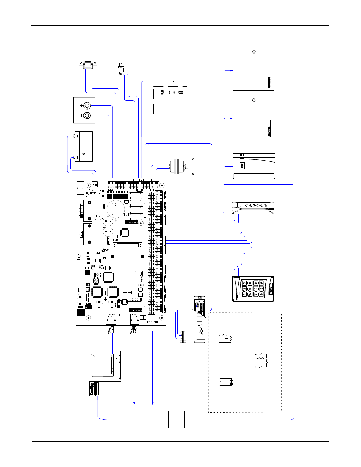
The KT-400 Ethernet Four-Door Controller is a full 4 onboard doors access controller. See Figure 1 for a description of
the PCB and Figure 2 for all the connection possibilities offered by the KT-400 Ethernet Four-Door Controller.
Communication Ports
• 1 10/100Base-T Ethernet for network connection with the EntraPass Gateway
• 1 RS-232 (COM3) for direct connection to the EntraPass Gateway and RS-485 communication with KT-100, KT-200,
KT-300 and KT-400
• 1 RS-485 (COM1) for RS-485 communication between the EntraPass Gateway and the KT-100, KT-200, KT-300 and
KT-400
• 1 SPI (Serial Peripheral Interface) port for expansion modules such as the KT-MOD-REL8 (8-Relay Outputs), the KTMOD-INP16 (16-Input) and the KT-MOD-OUT16 (16-Output)
IP Connectivity
The KT-400 Ethernet Four-Door Controller, when used with EntraPass Special Edition or a Corporate Gateway, can
report events, gather its configuration through an IP connection over the LAN (Local Area Network) and over the Internet
for a WAN (Wide Area Network). In this mode, the 1st or local controller becomes a “Master Controller” and can poll up
to 31 Kantech controller(s). The KT-400 Ethernet Four-Door Controller is compatible with all the controllers. Unlike the
other controllers, the KT-400 Ethernet Four-Door Controller asynchronously polls the controllers (KT-100, KT-200, KT-
300) and communicates with the EntraPass Gateway only when necessary. This significantly reduces the amount of
bandwidth required to operate your security system on the network.
• AES Encryption 128-Bit: The KT-400 Ethernet Four-Door Controller is extremely secure. It uses 128-bit AES
encryption to communicate with the Gateway which prev ents any hacking from the internet and ensures secure
communications when used over the internet on a wide area network (WAN).
DN1726-0811
5
Page 10

Inputs
There are 16 onboard inputs on the KT-400 Ethernet Four-Door Controller. Up to 240 more can be added through the
addition of expansion modules, such as the KT-MOD-INP16, for a total of 256 inputs. Each input can be individually
configured for one of the following application:
• Door contact (4 onboard)
• T.Rex (Request to Exit Detector) (4 onboard)
• Interlock (4 onboard)
• Floor Selection for Elevator Application
•Elevator Action
• External Alarm System Status (Armed / Disarmed)
• External Alarm System Alarm (Alarm / Secure)
• External Alarm System Zones
• Relays to trigger on each input in alarm event
• Zone shunt: Single or group of zones can be permanently or temporaril y 'shunted' to a secure state on the same
controller. Shunt method includes:
- Zone Shunt by another Zone - When a zone in alarm is programmed to shunt another zone / group of zones.
- Zone Shunt on Unlock - When a zone is temporarily frozen to its actual state (alarm or secured) after an access
granted.
- Manual Shunt - Operator can manually 'Shunt' a zone to a secure state.
- Disarmed Door Shunt - When alarm system is disarmed, some zones may be 'Shunted' to a secure state.
- Entry / Exit Delay Shunt - When a user is in the process of disarming / arming the alarm system and entry / exit
delay prevails, some zones may be 'Shunted' to a secure state.
• Arming / Disarming Request
• Postpone Arming Request
• Tamper switch input: The tamper switch is a non-programmable 'Fixed-Function' input. It is used to identify tampering of
the KT-400 cabinet.
Lock Outputs
There are 4 onboard lock outputs and they are supervised. The locking function can also be performed by any onboard
relay configured for this functionality.
Relay Outputs
There are 4 onboard relay outputs. Up to 256 relay output s can be supported th rough th e addition of exp ansion modul es
such as the KT-MOD-REL8.
Reader Outputs
There are 4 different possible outputs for each of the 4 onboard reader inte rfaces for a tot al of 16 programmable output s.
Reader outputs are used to give user visual and/or audible feedback on the ongoing access events.
Reader Interfaces
There are 4 onboard reader interfaces. They can be programmed for Wiegand or ABA (Clock and Data) readers.
Elevator Interface
The KT-400 Ethernet Four-Door Controller supports elevator interfacing with the addition of expansion modules such as
the KT-MOD-REL8, KT-MOD-INP16 and KT-MOD-OUT16.
Alarm Panel Interface
The KT-400 Ethernet Four-Door Controller supports alarm panel interfacing with the appropriate connections made
between zone inputs, relay outputs and the alarm system panel.
Automatic Port Detection
The KT-400 Ethernet Four-D oor Contro ller automatica lly detects the site communication speed set by EntraPass as well
as the communication port which can be IP (ETHERNET #1), RS-485 (COM1) or RS-232 (COM3).
6
DN1726-0811
Page 11

KT-400 Ethernet Four-Door Controller Installation Manual
Downloadable Firmware
The firmware program can be downloaded from any EntraPass workstation to the KT-400 Ethernet Four-Door Controller.
The firmware program, stored in the controller’s flash memory, is upgraded without having to change any parts.
Trouble and Reporting
The KT-400 Ethernet Four-Door Controller constantly supervises ac power and battery condition and reports “AC Lost”,
“Normal Battery”, “Low Battery”, “Battery Critical” or “No Battery”, status to the EntraPass system. Power outputs are
supervised and electronically protected against short-circuits and surges. Locking devices are also supervised for short
and open circuits.
Visual Status Indicators (LEDs)
The KT-400 Ethernet Four-Door Controller has multiple status indicators such as for troubleshooting, network activity,
power status and outputs activity. See Figure 1 for their locations.
- VITAL or Heartbea t: The VITAL blue LED indicates the communication status with EntraPass or the IP mode of the
controller. Refer to Table 1 for a descriptions of the heartbeat patterns.
- SPI Active (YELLOW): This LED signals activity on the SPI expansion port as well as communication between the
main CPU and the input/output CPU.
- COM1-RX, COM1-TX, COM2-RX, COM2-TX, RS232-RX and RS232-TX (YELLOW): The six serial port LEDs are
transmit/receive activity indicators. The COM2-RX and COM2-TX LEDs are for future use.
- LOCK1, LOCK2, LOCK3 and LOCK4 (RED): Each lock output (Open Drain) has an indicator which turns on each
time the corresponding output is activated.
- RELAY1, RELAY2, RELAY3 and RELAY4 (RED): Each relay output has an indicator which turns on each time the
corresponding relay is activated.
- AC PWR and DC PWR (GREEN): Theses LEDs are on when AC and DC power are present at the AC and/or DC
power input terminals.
- ETH1 LINK (GREEN): The LED is OFF when there is no Ethernet network or the cable is disconnected, and ON
when there is an Ethernet cable and network connection.
- ETH1 TXRX (YELLOW): The LED indicates network activity.
Built-in SPI Expansion
The KT-400 Ethernet Four-Door Controller allows connection of expansion modules in order to add outputs, like relays
and open drain outputs, and inputs. See Figure 10 and Figure 11 for an example with expansion modules.
- KT-MOD-REL8: The KT-MOD-REL8 is an 8-relay expansion module. Each relay is 3 Amps, 30 VDC Form C. The
module supports daisy-chaining which can add up to 32 KT-MOD-REL8 modules for a total of 256 relay outputs per
KT-400 Ethernet Four-Door Controller.
- KT-MOD-INP16: The KT-MOD-INP16 is a 16-zone input expansion module. The module supports daisy-chaining
which can add up to 15 KT-MOD-INP16 for a total of 240 external inputs per KT-400 Ethernet Four-Door Controller.
The KT-400 Ethernet Four-Door Controller has 16 onboard inputs which gives a total of 256 inputs per controller.
- KT-MOD-OUT16: The KT-MOD-OUT16 is a 16-output expansion module. Each output is capable of 750 mA. It
gives the opportunity to address the need for external LED, lock, relay, piezo and buzzer control. The module
supports daisy-chaining which can add up to 16 KT-MOD-OUT16 modules for a total of 256 external open drain
outputs per KT-400 Ethernet Four-Door Controller.
Note: The expansion modules support daisy chaining which can add up to 32 KT-MOD-REL8 modules for a total of 256
external relays per KT-400 Ethernet Four-Door Controller. Combining input and output expansion modules gives the
flexibility to connect up to 256 inputs and 256 outputs.
DN1726-0811
7
Page 12
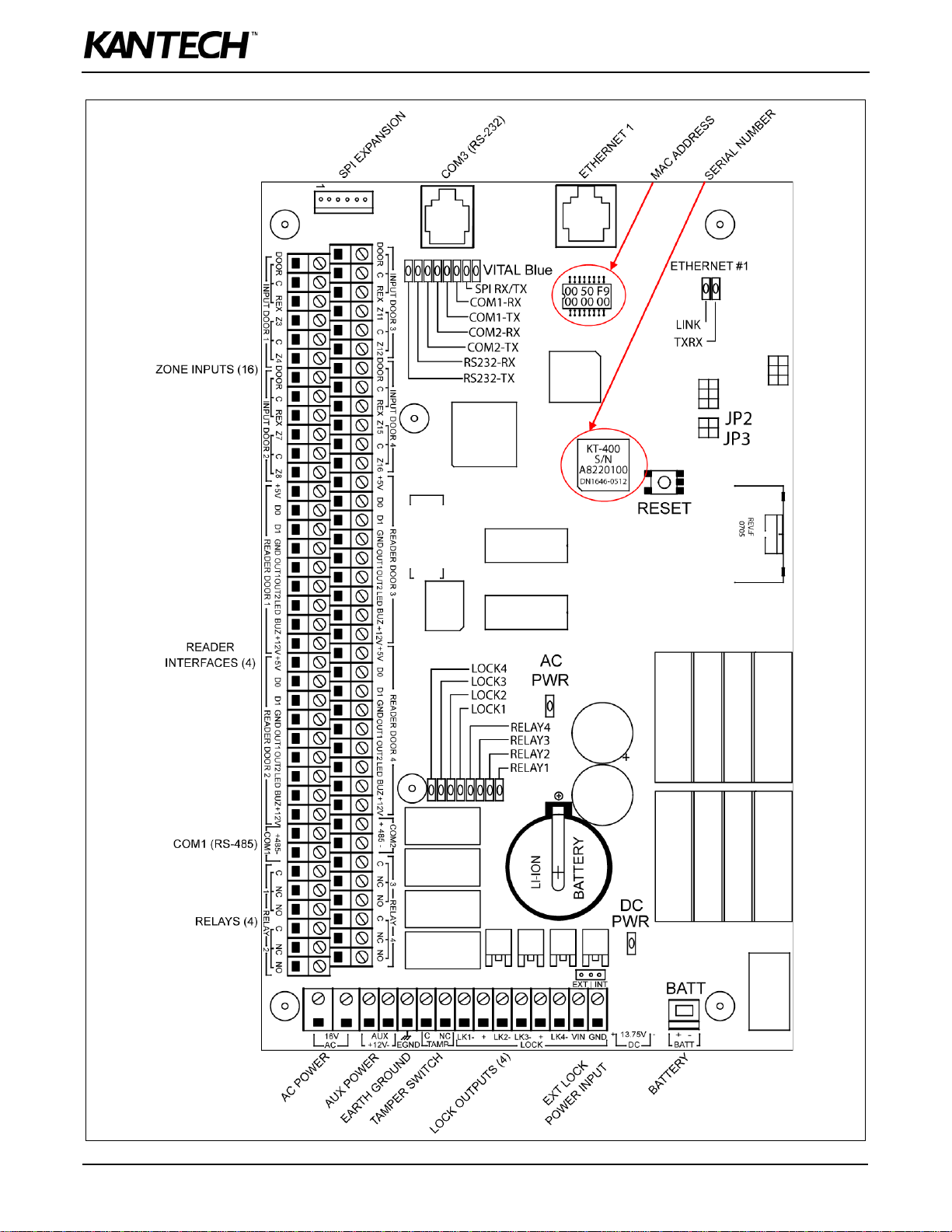
Figure 1: KT-400 Ethernet Four-Door Controller PCB View
8
DN1726-0811
Page 13
KT-400 Ethernet Four-Door Controller Installation Manual
10/100 BASE-T ETHERNET PORT
COMPUTER NETWORK
KT-300
KT-100
RS485 BUS (COM1)
TAMPER
NC
C
NC
Z3
NC DRY CONTACT
INPUT DEFINED OPTION
WITH DOUBLE EOL RESISTORS
INPUT DEFINED
RED
BLACK
7 A/H MINIMUM
12V BATTERY
WITH EOL RESISTOR
INPUT DEFINED
DRY CONTACT
NO
OR NC
WITHOUT EOL RESISTOR
DRY CONTACT
NC
OR NO
1200-115200 BAUDS DEVICE
LOW SPEED RS232C
WITH INTEGRATED KEYPAD
IOPROX P325KP READER
BROWN
BLUE
RED (+12V)
BLACK
WHITE
GREEN
BROWN
BLUE
BLACK
RED (+5V)
WHITE
GREEN
POLARIS 2 READER
WITH INTEGRATED
KEYPAD
NO
NC
CZ3
(CONNECT 1K RESISTOR
WHEN INTERNAL PWR USED
12-13.75 VDC, 1 AMP MAX
DOOR LOCKING DEVICE
Z3C Z4
SPI EXPANSION PORT
OPTIONAL
INPUT CONFIGURATIONS
12-28 VDC POWER
LOCKING DEVICES SUPPLY
12-28 VDC, 3 AMPS MAX
OPTIONAL EXTERNAL
IF NOT USED)
OPTIONAL
TAMPER SWITCH
DOOR 1 CONTACT
DOOR 1
REQUEST TO EXIT DEVICE
12VDC PWR
R
R
RS485 from USB-485
USB
ACCESS CONTROL AND INTEGRATED SYSTEMS
TM
POLARIS
*
9 0
7 8
5 6
3 4
1 2
SEALED RECHARGEABLE
BATTERY
12 VOLT
7 AMP/HR
KT-400
ACCESS CONTROL AND INTEGRATED SYSTEMS
KT-300
KT-400
USB-485
0506
+12V-
COM2-RX
RS232-RX
INPUT DOOR 3
COPYRIGHT (C) 2007 TYCO INTERNATIONAL LTD.
RELAY4
RED
EGND
GND+5V
LK4-
LK2-LK1-
BUZ GND
4
GND+LK3-
LOCK
VIN
+
C
TAMP
NC
RS-232
ETHERNET #1
3
C NC NO C NC NO
RELAY
21
CCNCNO NCNO
RELAY
COM2
+485-
AUX
BUZ +12VD1+5V D0 GND GRN YEL
READER DOOR 2
RED BUZD1+5V D0 GRN YEL
READER DOOR 3
RED BUZ +12VD1D0 GRN YEL
READER DOOR 1
RED +12VD1+5V D0 GRN YELDOOR REX Z3 C Z4
INPUT DOOR 1
DOOR C REX Z7 C
Z8
INPUT DOOR 2
DOOR C REX Z11 C Z12 DOOR C REX C Z16
INPUT DOOR 4
READER DOOR 4
Z15
C
P/N:566-472K
REV.:E
+485-
COM1
+12V
HEARTBEAT
SPI ACTIVE
COM1-RX
COM1-TX
COM2-TX
RS232-TX
LOCK4
LOCK3
LOCK2
LOCK1
RELAY3
RELAY2
RELAY1
AC PWR
CPU JTAG
CPLD JTAG
RESET
SPI
LCD MODULE
ETH2 TXRX
ETH2 100
ETH1 TXRX
ETH1 100
GND
EXT | INT
16V
AC
13.75V
DC
+ -
BATT
+
-
DC PWR
Y6
U36
U35
Q56
Q53
Q51
PTF8
PTF7
PTF6
P8
L9
D22
HS3
HS2
HS1
Y3
Y1
Y2
Y4
U13
U26
U9
U20
U22
U2
U28
U24
U17
U6
U14
U5
U25
U7
U3
U23
TR2
TR1
SW2
RV1
R23
R12
Q3
Q4
Q6
Q7
PTF1
PTF3
P3
P6
P2
P1
P5
L1
L5
L4
L2
L3
K2
K4
K1
JP4
JP2 JP3
DL14
DL12
DL18
DL16
DL4
DL3
DL5
DL19
DL17
DL2
DL11
DL8
DL15
DL13
DL7
DL6
DL10
DL9
DL21
DL20
DL1
C27
C28
C29
BT1
P7
J2
J4
R5
D3
CON1
SW1
DL22
EARTH GROUND
CABINET
PEM
LOCKNUT
JUMPER JP4 ON EXT
JUMPER JP4 ON INT
120 VAC, 60 Hz IN
16 VAC, 75 VA OUT
CLASS 2, WIRE-IN
Figure 2: KT-400 Ethernet Four-Door Controller Inputs and Outputs View
DN1726-0811
9
Page 14

Figure 3: KT-400 Cabinet Model for North America
10
DN1726-0811
Page 15

KT-400 Ethernet Four-Door Controller Installation Manual
System Architecture
The KT-400 Ethernet Four-Do or Controller can be used through va rious si te applications w ith EntraPass Special Edition,
EntraPass Corporate Edition and EntraPass Global Edition.
Applications with EntraPass Special Edition and Corporate Edition with Corporate Gateway.
• Over the internet. See Figure 4.
• Over RS-232 with a USB-485. See Figure 5.
Application with EntraPass Global Edition and a Global Gateway.
• Over RS-232 with a VC-485. See Figure 6.
Application with EntraPass Global Edition and a KT-NCC.
• Over the internet with a KT-NCC. See Figure 7.
Application with EntraPass Special Edition, Corporate Edition and Global Edition.
• Over RS-232 straight from EntraPass RS-232 COM port. See Figure 8.
Figure 4: Over the Internet with EntraPass Special Edition and Corporate Edition with Corporate Gateway
DN1726-0811
11
Page 16

Figure 5: USB-485 with EntraPass Special Edition and Corporate Edition with Corporate Gateway
Figure 6: VC-485 with EntraPass Global Edition and Global or Corporate Gateway
12
DN1726-0811
Page 17

KT-400 Ethernet Four-Door Controller Installation Manual
Figure 7: Over the internet with a KT-NCC and EntraPass Global Edition
Figure 8: Over RS-232 straight from the EntraPass RS-232 COM port
DN1726-0811
13
Page 18

VITAL LED Heartbeat Patterns
Communication status and other vital controller parameters can be obtained from VITAL LED heartbeat patterns. It is
located near the RS-232 port (COM3), see Figure 1. This information is particularly useful when connecting the
controller to the rest of the EntraPass system. The fo llow ing table lists all conditions along with a brief d escription . Refer
to Table 3, if you must reset or change the communication mode of the KT-400 Ethernet Four-Door Controller.
Table 1: VITAL LED Heartbeat Patterns
Booting Up Steady
Factory Default DHCP Continuous LONG Pulses
Unable to Resolve DNS 2 LONG Pulses
Forced Default Static 3 LONG Pulses
DHCP Server Failed 4 LONG Pulses
Receive Broadcast Single 2.5 Sec. Burst
Card Read or Swipe
Hard Reset 4 SHORT Pulses
Corporate Gateway 3 SHORT Pulses
Global Gateway 1 SHORT Pulse
Fail Soft Continuous SHORT Pulses
Firmware Update 5 pulses / sec @ 50% duty cycle
Rebooting 10 pulses / sec @ 50% duty cycle
Single 0.5 sec burst, resume
previous flash
14
DN1726-0811
Page 19

KT-400 Ethernet Four-Door Controller Installation Manual
Technical Specifications
Type Description
Power input (KT-400) Transformer class 2, IN 120 VAC; OUT 16 VAC, 75 VA
Battery back-up (KT-BATT-12) 12 VDC, 7 Ah battery supervised, provides up to 12 hours of operation
Operating Temperatures From 2°C to 49°C (35°F to 120°F) indoor use only
Humidity Level 0 to 85% (relative humidity non-condensing).
Cabinet Dimensions
(High-Wide-Deep)
Cabinet Weight (KT-400) 4.0 kg (8.82 lb)
PCB dimension 22.86 cm (9 in) X 13.97 cm (5.5 in) X 5.20 cm (2.04 in)
Reader types Wiegand, proximity, ABA Clock and Data, bar code, magnetic, integrated keypad,
Reader power output 12 VDC and 5 VDC @ 175 mA max each, protected and supervised
Monitored points (inputs) 16 monitored points, single EOL (End of Line), double EOL, without EOL and
Points maximum wiring AWG #22 - 600 m (2,000 ft)
Door strike power 12 VDC, 250 mA max for KT-400 supervised
Reader outputs 16 outputs, 25mA max each, open collector outputs
Auxiliary outputs LEDs (LED, OUT1 and OUT2) and buzzer (Buz) for each individual door, 25mA max each,
Relay controlled output 4 onboard Form C Relay controlled outputs, 30 VDC, 3 Amps max each
Communication ports 1 x RS-232 with RJ-12, 1 x RS-485, 1 x Ethernet 10/100Base-T with RJ-45
Expansion port 1 x SPI 6-pin connector , bidirectional data exchange supported. Supplies 12 VDC, 500 mA
37.59 cm (14.8 in) x 30.48 cm (12.0 in) x 12.57 cm (4.95 in)
smartcard and others
1 fixed-function tamper switch input
open collector outputs
max shared with 12 VDC Auxiliary port
Auxiliary port 1 x Auxiliary 12 VDC, 500 mA maximum shared with SPI expansion port
Communication speed - Up to 115200 Bauds (automatic detection) over RS-232 and RS-485
- 10/100 Mb/s BaseT over Ethernet
Flash memory 16 MB for application storage
RAM memory 64 MB for application loading and running, protected by a Lithium-Ion battery for a
minimum of 75 hours
Network autonomy Distributed data and processing
Certifications / Listing EN55022, EN61000-6-1, EN61000-6-2
FCC: Class A
UL 294, UL 1076
DN1726-0811
15
Page 20

Electrical Specifications
OPEN COLLECTOR OUTPUTS MAXIMUM CURRENT
(T ypical)
LEDs (LED, OUT1 and OUT2) for each door reader 25 mA (each)
Buzzer (Buz) for each door reader 25 mA (each)
COMBINED MAXIMUM
CURRENT
OUTPUTS MAXIMUM CURRENT
1 for 12 VDC Auxiliary Power (11.2 to 13.75 VDC) polyswitch
protected, shared with SPI expansion port
4 for Controlled Readers (11.2 to 13.75 VDC) 500 mA
4 for Controlled Readers 5 VDC 400 mA
4 for Locks (11.2 to 13.75 VDC) when jumper JP4 is on INT
(internal)
4 for Locks (11.2 to 28 VDC) when jumper JP4 is on EXT
(external)
500 mA
1 Amp for KT-400
2 Amps for KT-400
3 Amp
KT-400 Ethernet Four-Door Controller Models, Expansion Modules Models, Related Documentation and Miscellaneous Items
Part number Description
KT-400 Ethernet Four-Door Controller Models
KT-400 KT-400 Ethernet Four-Door Controller, IP Ready with Accessory Kit in Metal Cabinet, see Table 2
KT-400-PCB KT-400 Ethernet Four-Door Controller PCB only, IP Ready with Accessory Kit, see Table 2
KT-400-CAB KT-400 Black Metal Cabinet with Lock and Keys, see Table 2
Expansion Modules Models
KT-MOD-INP16 KT-400 Expansion Module 16-Zone Inputs with SPI Cable 41 cm (16 in)
KT-MOD-REL8 KT-400 Expansion Module 8-Relay with SPI Cable 41 cm (16 in)
KT-MOD-OUT16 KT-400 Expansion Module 16-Output with SPI Cable 41 cm (16 in)
KT-MOD-CAB KT-400 Expansion Module Cabinet, Black, with SPI Cable 91 cm (36 in), Lock and Two Keys
KT-MOD-SPI16 KT-400 SPI Cable 41 cm (16 in) for SPI Interconnection within the Cabinet
KT-MOD-SPI36 KT-400 SPI Cable 91 cm (36 in) for SPI Interconnection between Cabinets
Related Documentation
DN1420 EntraPass Special Edition, Reference Manual - English version
DN1415 EntraPass Corporate Edition, Reference Manual - English version
DN1316 EntraPass Global Edition, Reference Manual - English version
DN1474 EntraPass Special Edition, Reference Manual - French version
16
DN1435 EntraPass Corporate Edition, Reference Manual - French version
DN1289 EntraPass Global Edition, Reference Manual - French version
DN1726-0811
Page 21

KT-400 Ethernet Four-Door Controller Installation Manual
Part number Description
DN1475 EntraPass Special Edition, Reference Manual - Spanish version
DN1436 EntraPass Corporate Edition, Reference Manual - Spanish version
DN1599 EntraPass Global Edition, Reference Manual - Spanish version
DN1514 EntraPass Special Edition, Reference Manual - German version
DN1598 EntraPass Corporate Edition, Reference Manual - German version
DN1597 EntraPass Global Edition, Reference Manual - German version
DN1684 EntraPass Special Edition, Reference Manual - Italian version
DN1683 EntraPass Corporate Edition, Reference Manual - Italian version
DN1682 EntraPass Global Edition, Reference Manual - Italian version
DN1796 Networking Basics, Application Note, English version
Dimensions Drawings
DN1846 KT-400-PCB Dimensions Drawing in DWG Format
DN1847 KT-400-PCB Dimensions Drawing in PDF Format
DN1848 KT-400-CAB Dimensions Drawing in DWG Format
DN1849 KT-400-CAB Dimensions Drawing in PDF Format
Miscellaneous Items
CBLK-10 Cable kit, RS-232 cable 30 m (100 ft) with RJ-12 connectors for PC to master KT-400, 740-1023
(DB9F to RJ-12) adaptor and 740-1041 (DB9M to DB25F) adaptor
USB-485 USB-485 interface, USB cable 0.9 m (3 ft) and USB drivers on CD-ROM
VC-485 VC-485 interface, RS-232 cable 3 m (10 ft) with RJ-12 connectors, 740-1012 (DB25F to RJ-12)
adaptor, 740-1022 (DB9F to RJ-12) adaptor and 740-1033 (DB25M to RJ-12) adaptor
KT-3LED-PLATE Three-color LED alarm indicator mounted on single plate
KT-ACPW-LED AC power LED indicator
KT-LOCK Keylock for cabinet with 2 keys
KT-SW1224 Internal Power Supply 12 VDC, 2 Amps, 24 Watts
KT-TAMPER Tamper switch for cabinet
DN1726-0811
17
Page 22

Models Information
• KT-400: Cabinet with one KT-400 for North America, up to three expansion modules can be installed in the cabinet,
• KT-400-PCB: KT-400 with parts,
• KT-400-ACC: Accessory kit,
• KT-400-CAB: Cabinet only for North America,
Table 2: Models Bills of Material
Item Description KT-400
(Notes 1,2)
KT-400 PCB 1 1 - -
Cabinet 1 - - 1
KT-400-ACC Accessory Kit 1 1 - -
Ground wire (PCB to cabinet) 1 1 - -
Ground wire (door to cabinet) 1 1 - 1
Tamper switch 1 - - -
Battery cable 1 - - -
Resistor 5.6K, 0.5W - - 32 -
Resistor 1K, 0.5W - - 4 -
Inner door sticker for North America,
DN1762, Figure 14
Installation Manual DN1725 - French 1 1 - -
Installation Manual DN1726 - English 1 1 - -
Note 1: The KT-400, KT-400-CAB models also include the KT-LOCK.
Note 2: The KT-400, KT-400-PCB models also include screws and locknuts.
1- - 1
KT-400-PCB
(Note 2)
KT-400-ACC KT-400-CAB
(Note 1)
18
DN1726-0811
Page 23

KT-400 Ethernet Four-Door Controller Installation Manual
Installing the KT-400 Ethernet Four-Door Controller
Preparing to Install the KT-400 Ethernet Four-Door Controller
Required to install KT-400 Ethernet Four-Door Controller
• For North America: AC transformer 120 VAC 60 Hz IN; 16 VAC, 75 VA OUT; class 2 (not included)
• One battery 12 VDC, 7 Ah (not included)
• Ground clamp (not included)
A visual inspection should be made when unpacking th e KT-400 Ethernet Four-Door Con troller . Any missing item/p art or
damaged component should be reported immediately.
Physical Installa tion
Check for ideal indoor location
Stay away from electrical or communication devices
The KT-400 cabinet has been designed to be mounted on a wall without any additional enclosures. The cabinet is large
enough to accommodate the battery backup supply and the necessary wiring connections for most applications. EMT
(Electrical Metallic Tubing) conduit knockouts are provided in 1.9 cm (0.75 in) on all sides of the cabinet.
The cabinet should be mounted indoors, in a secure location providing normal temperature and humidity, leaving 23 cm
(8 in) clear space around all sides and a minimum of 33 cm (13 in) clear space in front of the cabinet. The loca tion should
be easily accessible for servicing the equipment and it is recommended that controllers be located close to the controlled
doors.
Controllers must be located at a minimum distance of 2 m (6 ft) from any high voltage equipment or wiring and from
electrical equipment susceptible of generating electrical interference, at a minimum distance of 1 m (3 f t) from telepho ne
equipment or lines, and at a minimum of 8 m (25 ft) from any transmitting equipment. Physical access, using keys, on
controlled doors must be provided so that the KT-400 Ethe rnet Four-Door Controller can easily be accessed for servicing
in case of malfunction.
Earth Grounding
AWG #18 grounding wire to EGND
Since the KT-400 Ethernet Four-Door Controller uses high performance communication, proper grounding must be
provided to ensure proper operation.
An AWG #18 single conductor copper wire must be used to ground each controller to good earth ground as
per the local electrical code (be careful with ground loops). The ground clamp shou ld be locate d below any
other ground.
Door Locking Devices
Connect the door lock device to + and LK1-, (+ and LK2 -),
(+ and LK3- ) or (+ and LK4-)
Note: If you need additional power for ALL the external locks, you can use an
external +power supply. Connect the power supply to the VIN and GND
terminals and put jumper JP4 on EXT.
When jumper JP4 is on INT, the total maximum current draw is
1 Amp for KT-400 at 12 to 13.75 VDC, or
When jumper JP4 is on EXT, the total maximum current draw is
3 Amps at 12 to 28 VDC
Check for local “magnetic lock” regulations
LK1-, LK2-, LK3- and LK4- and + terminals are located near the battery
(BATT) terminals. The locking device outputs are controlled according to the end-user programmed parameters for
allowing access to or unlocking doors according to schedules and access levels. These d oors locking device output s can
operate DC powered locking devices such as electromechani cal strikes and can be con figured to operate fail-sa fe or failsecure (normal or reverse action).
Note: Use 1 K ohm EOL (End-of-Line resistor) between + and LK- terminals if not used.
DN1726-0811
19
Page 24

Warning: Controlled door locks may be governed by regulatory bodies and should always be installed according to local
regulations. In most instances, there are strict limitations to installing fail-secure devices and fail-safe locking devices
such as magnetic locks or other similar locking devices on doors used as emergency exits.
Hooking Up Inputs
Connect devices to inputs 1 to 16
Resistors for all inputs 5.6K ohm (if selected)
The KT-400 has an on-board capability of monitoring 16 input points
(expandable to 256 with expansion modules). Each onboard input is
supervised with or without end-of-line resistors (5.6K ohm). The
maximum distance of one line is 600 m (2,000 ft) with AWG #22 in a
single or double EOL configuration.
Note: Onboard Inputs can be defined with: none, single or double EOL
(End-of-Line) resistor(s) according to your EntraPass software
settings.
Inputs 1-2 are automatically reserved for the first controlled door.
The contact is assigned input 1 and the associated request-to-exit
detector as input 2. Inputs 5 and 6 are automatically reserved for the
second controlled door. The contact is assigned input 5 and the
associated request-to-exit detector as input 6. Inputs 9 and 10 are
automatically reserved for the third co ntrolled door. Inputs 13 and 14
are automatically reserved for the fourth controlled door. There is no
obligation to follow these rules but this standard convention
facilitates servicing.
Connect readers and keypads
READER CONNECTION TERMINAL WARNING
Connecting the red wire lead (or power lead) of a 5 VDC reader to
the 12 VDC terminal may damage the reader. See your reader
installation procedure for proper power connection. U p to 4 readers can be conne cted to a KT-400. They can be inst alled
on one door to control both entry and exit or on four separate doors operating independently to control one-way access.
The distance between the readers and the KT-400 varies by reader type (please consult the installation manual for
details). Auxiliary outputs provide visual and/or audible access operation feedback at the controlled door. Outputs
“READER DOOR 1 - OUT1 OUT2 LED & BUZ” are used for the first door, “READER DOOR 2 - OUT1 OUT2 LED &
BUZ” are used for the second door, “READER DOOR 3 - OUT1 OUT2 LED & BUZ” are used for the third door and
“READER DOOR 4 - OUT1 OUT2 LED & BUZ” are used for the fourth door.
20
DN1726-0811
Page 25

KT-400 Ethernet Four-Door Controller Installation Manual
Relay Controlled Outputs
The KT-400 provides four relay outputs RELAY1 to RELAY4 (3
Amps, 30 VAC/VDC). The KT-400 can be expanded up to 256
controlled outputs when using expansion modules.
• The KT-MOD-OUT16 module provides 16 outputs at a maximum of
750 mA per output.
• The KT-MOD-REL8 module provides 8 relay outputs at a maximum
of 3 Amps per relay.
Note: Since the KT-400 maximum output current draw on the SPI
expansion port is 500 mA when the 12V AUX terminals are not
used, an external power supply of 12 VDC, 2 Amps is required
when adding expansion modules to the same KT-400. See
“SPI Expansion Port” on page 24 for additional details
concerning the external power supply requirement for
expansion modules.
Auxiliary Outputs
Connect auxiliary outputs to readers and local warning
devices
Auxiliary outputs are used for visual and audible signal. They can
be activated according to input conditions or events and local
alarms. Auxiliary outputs “READER DOOR 1 to 4 - LED” provide
visual feedback of access operation, and auxiliary outputs “READER DOOR 1 to 4 - BUZ” can activate audible warning
devices, such as T-REX or reader buzzer, to signal door alarms.
T amper Protection
Install tamper switch on cabinet
A tamper switch must be installed on the unit to detect unauthorized cabinet opening.
The normally closed tamper switch must be connected to the dedicated tamper input, next to the EGND.
Note: The tamper switch is required for a UL listed installation.
DN1726-0811
21
Page 26

Connecting the KT-400 Ethernet Four-Door Controller
VC-485
(Preferred for Global Edition)
USB-485
(Preferred for Special Edition and
Corporate Edition)
RS232
GND
V+
GND
X- X+
RJ-12
V+
RECEIVE
TRANSMIT
PWR
RS-485
ORANGE
BLUE
WHITE
Up to 1.2 Km (4000 ft )
to the last controller
WHITE
BLUE
ORANGE
ORANGE
BLUE
WHITE
Max 30 m (100 ft)
DB25F
DB9F
VC-485
RS-232 / RS-485 CONVERTER
KANTECH SYSTEM INC.
Montreal - Canada
X+ X- GND
USB-485
RX
TX
PWR
USB
Powered from USB port
RS-485
DN1485-0302
To USB Port
To RS-232 Port
Max 0.9 m (3 ft)
POWER
GND V+
RS-232
GND
RS-485
X- X+
6 CTS WHITE
1 RTS BLUE
2 GND YELLOW
3 TX GREEN
4 RX RED
5 GND BLACK
RJ-12
Connecting the VC-485 or the USB-485 to the RS-485 Bus
Connect the RS-485 cable to (COM1) + 485 - and the RS-485 signal ground to the 12 VDC AUX - (negative)
Controllers are linked together through their RS-485 terminals. The maximum communication loop length is 1.2 km
(4,000 ft) using appropriate cabling. The RS-485 communication loop should be wired with Ethernet Category 3 double
twisted pair network cable or better. The RS-485 loop can operate from 1200 to 115200 Bauds under normal conditions.
Intermittent communication problems or erratic operation may require network speed drops to 9600 or 19200 Bauds.
Varying the network speed does not perceptibly change the operation speed of the system.
Note 1: Most installations should be set to 38400 Bauds.
Note 2: Connecting several KT-400 at a single point is not recommended neither are splitters or spider web (star) networks.
Note 3: If the 12 VDC - is already used, the RS-485 signal ground can be connected to the other GND terminals on the KT-400.
The EGND (earth ground) terminal cant be used for signal ground, only use the GND and 12 VDC - (negative)
terminals for signal ground.
Note 4: There is no end-of-line resistor to install on the RS-485 COM1 terminals on the last KT-400 controller of a loop.
Note 5: If you must make up your own RS-232 cable
with a RJ-12 connector, refer to the following
diagram for the RJ-12 pin-out.
DN1726-0811
22
Page 27

KT-400 Ethernet Four-Door Controller Installation Manual
Connecting the Master Controller to the Host PC via RS-232
Connect RS-232 cable from KT-400 to the PC (maximum length 30 m (100 ft))
If the local master controller is located more than 30 m (100 ft) from the host computer, you must use a VC-485 or
USB-485 interface.
Note 1: The CBLK-10 kit includes 30 m (100 ft) of RS-232 cable with RJ-12 connectors and the 740-1023 (DB9F to RJ-12)
adaptor
Note 2: If you must make up your own RS-232 cable with RJ- 12 connectors, refer to the following diagram for the RJ-
12 pin-out.
Connecting over Corporate Network (LAN)
If the master controller is used in a LAN-enabled corporate setting, u se the RJ-45 Ethernet port to connect the controller
to the corporate network. This method uses existing wiring for data exchange between EntraPass and the controllers.
Powering the KT-400 Ethernet Four-Door Controller
Install 120 VAC IN / 16 VAC, 75 VA OUT, class 2 transformer
Place battery in cabinet
Power up the KT-400 Ethernet Four-Door Controller
The KT-400 must be powered by a 16 VAC, 75 VA class 2 wire-in or plug-in transformer.
After you have completed all the necessary steps, you can power up the KT-400. Connect AC power and connect the
battery. Once powered, check the VITAL LED status indicator to determine the status of communication and other vital
parameters. Consult Table 1 for VITAL LED behavior identifications.
If the AC supply is removed, the 12 VDC, 7 Ah backup battery will support normal operation for up to 12 hours, if fully
charged. Internal battery verification will cutoff battery power if the battery voltage level falls below 9.5 Volts.
Note: The KT-400 will not start on battery power alone.
Power should only be applied to the unit when all connections are completed and
tested.
DN1726-0811
23
Page 28

SPI Expansion Port
The SPI (Serial Peripheral Interface) expansion port on the KT-400 is used to connect expansion modules, in order to
add more inputs and outputs such as relays. The maximum current draw for the SPI exp ansion port is 500 mA when the
12V AUX terminals are not used. The 6-pin SPI cable must be connected to the SPI IN of the first module. See Figure 9
and Figure 11 for examples of interconnection between the KT-400 and expansion modules.
Figure 9: KT-400 Interconnection Examples with Expansion Modules
The number of expansion modules that can be connected to the KT-400 SPI expansion port, without an additional
external power supply, can vary depending how much current is drawn from all the modules in the SPI chain.
Check the following table to calculate the SPI chain current draw:
Expansion Module Qty of modules x Maximum current draw Total
Current
KT-MOD-REL8 _______ x 330 mA ______ mA
KT-MOD-INP16 _______ x 40 mA ______ mA
KT-MOD-OUT16 _______ x 750 mA ______ mA
Maximum current draw from KT-400 SPI expansion port when the 12 VDC AUX terminals are not used. - 500 mA
If the total current is between 0 mA and 1850 mA (1.85 Amps), 1 external power supply is required.
If the total current is between 1851 mA and 3700 mA (3.70 Amps), 2 external power supply are required.
Example of current draw calculation:
1. 15 modules (KT-MOD-OUT16) x 750 mA = 11250 mA
2. 11250 mA - 500 mA (or 0 mA if the 12 VDC AUX of the KT-400 is used) = 10750 mA
3. 10750 mA divided by 1850 mA = 5.8 which means in fact 6 external power suppli es 12 VDC, 2 Amps are requi red.
4. Connect an external power supply at every expansion module where the current draw has reached 1.85 Amps.
5. Make sure the power jumper on the modules is in the correct position when using external power supply(ies).
24
DN1726-0811
Page 29

KT-400 Ethernet Four-Door Controller Installation Manual
Important Installation Rules about Expansion Modules
Note 1: The maximum current draw must be calculate each time there is a new module added to the SPI chain.
Rule 2: The SPI cable, between the KT-400 and the 1st module or between each modules, cannot exceed 1 m (3 ft). Shielded
wire should only be used in areas with excessive RF noise of electromagnetic interference. Keep in mind that the
expansion modules must be defined in the EntraPass system when they are installed.
Rule 3: There is already 4 relays available on the KT-400 Ethernet Four-Door Controller. Don't forget to check the relays
number assignments to prevent redundancy unless it has been planned on purpose.
For more details concerning the expansion modules, refer to the following documents:
Part number Description
DN1775 KT-MOD-INP16 Install Sheet - French version
DN1776 KT-MOD-INP16 Install Sheet - English version
DN1780 KT-MOD-OUT16 Install Sheet - French version
DN1781 KT-MOD-OUT16 Install Sheet - English version
DN1785 KT-MOD-REL8 Install Sheet - French version
DN1786 KT-MOD-REL8 Install Sheet - English version
DN1805 KT-MOD-CAB Install Sheet - French version
DN1806 KT-MOD-CAB Install Sheet - English version
DN1790 Expansion Modules Dimensions Drawing in DWG format
DN1791 Expansion Modules Dimensions Drawing in PDF format
DN1792 KT-MOD-CAB Dimensions Drawing in DWG Format
DN1793 KT-MOD-CAB Dimensions Drawing in PDF Format
DN1726-0811
25
Page 30

Figure 10: PCB View of Expansion Modules
26
DN1726-0811
Page 31

KT-400 Ethernet Four-Door Controller Installation Manual
MOTION DETECTOR
BUZZER
POWER
TAMPER
-++-
NO1NC1C1
12 VDC
CONTACT
DOOR LOCKING DEVICE
BUZZER
REGULATED POWER
SUPPLY 12 VDC, 2 Amps
FROM EXTERNAL SOURCE
REGULATED POWER
SUPPLY 12 VDC, 2 Amps
FROM EXTERNAL SOURCE
CONNECTION TO
OTHER INPUT
SPI OUT
MODULE
CONNECTION TO
OTHER OUTPUT
SPI IN EXT
MODULE
KT-MOD-REL8
KT-MOD-OUT16
LED
Neg
Pos
Neg
Pos
Neg
Neg
Pos
Pos
Pos
Neg
NC
65
CCNCNO
RELAY
SPI IN
GRN BLK REDYELWHT
1
CCNCNO
RELAY
NO
C 2007-08
43
CCNCNO NC
RELAY2
NC NO
BLU
SPI OUT
EXT
INT
PWR
0801 REV.A-1
566-494K
DC
EXT PWR
PCA
12V
+-
8
NC NO
WBGYRBK
7
CCNCNO
RELAY
NO
SPI MODULE
8 RELAYS
NC
6
5
CCNCNO
RELAY
SPI IN
GRN BLK REDYELWHT
1
CCNCNO
RELAY
NO
C 2007-08
43
CCNCNO NC
RELAY2
NC NO
BLU
SPI OUT
EXT
INT
PWR
0801 REV.A-1
566-494K
DC
EXT PWR
PCA
12V
+-
8
NC NO
WBGYRBK
7
CCNCNO
RELAY
NO
SPI MODULE
8 RELAYS
SPI OUT
5 - 24 VDC
OPTIONAL EXTERNAL
HIGH POWER SOURCE
566-493K
EXT PWR
ABSOLUTE TOTAL OUTPUTS
INTERNAL or EXTERNAL SUPPLY
12 VDC, up to 750 mA
O2
SPI IN
YEL REDWHTBLU BLKGRN
Pos
LED
Neg
+
O1
O11
24VDC
O12
+
O16
+
O14
+
O13 O15
EXT
INT
PWR
O10
Pos
Neg
OUTPUT DEVICE
5 to 24 VDC
up to 750 mA
BUZZER
Neg
O4+
O3
O8+O6+
O5 O7
+
O9
PCA
-+
DC
12V
GBKBW RY
-+
DC
12V
C 2007-08
0801 REV.A-0
16 OUTPUTS
SPI MODULE
Z12
SPI IN
EOL FAST NO
NCSLOWDRY
BLU
VITAL
CZ6
Z7
Z8Z4CZ2
Z3
C
Z5
C
Z10
C
Z9 Z11
C
Z1
YEL REDWHT BLKGRN
GBKRYBW
SPI EXP
C 2007-08
1
ON
JP4
BK
566-492K
EXT PWR
Z16
C
Z14
C
Z15
INT
EXT
PWR
GBW Y
-+
DC
12V
PCA
-+
DC
12V
Z13
SPI OUT
16 ZONES
0801 REV.A-1
SPI MODULE
R
Z12
SPI IN
EOL FAST NO
NCSLOWDRY
BLU
VITAL
CZ6
Z7
Z8Z4CZ2
Z3
C
Z5
C
Z10
C
Z9 Z11
C
Z1
YEL REDWHT BLKGRN
GBKRYBW
SPI EXP
C 2007-08
1
ON
JP4
BK
566-492K
EXT PWR
Z16
C
Z14
C
Z15
INT
EXT
PWR
GBW Y
-+
DC
12V
PCA
-+
DC
12V
Z13
SPI OUT
16 ZONES
0801 REV.A-1
SPI MODULE
R
Z12
SPI IN
EOL FAST NO
NCSLOWDRY
BLU
VITAL
CZ6
Z7
Z8Z4CZ2
Z3
C
Z5
C
Z10
C
Z9 Z11
C
Z1
YEL REDWHT BLKGRN
GBKRYBW
SPI EXP
C 2007-08
1
ON
JP4
BK
566-492K
EXT PWR
Z16
C
Z14
C
Z15
INT
EXT
PWR
GBW Y
-+
DC
12V
PCA
-+
DC
12V
Z13
SPI OUT
16 ZONES
0801 REV.A-1
SPI MODULE
R
KT-MOD-REL8
KT-MOD-INP16
KT-MOD-INP16
KT-MOD-INP16
TO KT-400 CONTROLLER
Neg
Jumper JP5
on EXT
Jumper JP5
on INT
Jumper JP5
on INT
Jumper JP1
on INT
Jumper JP1
on INT
Jumper JP1
on EXT
Figure 11: Example of KT-400 Ethernet Four-Door Controller Interconnection with Expansion Modules
DN1726-0811
27
Page 32

Figure 12: Expansion Modules Cabinet for North America
28
DN1726-0811
Page 33

KT-400 Ethernet Four-Door Controller Installation Manual
Troubleshooting
Table 3: Reset Types and Descriptions
Jumpers Heartbeats Patterns Resets
Soft Reset:
When JP2 and JP3 are ON, the controller will reset
on a) power up, b) pushbutton, or c) EntraPass
software 'Manual operator soft reset':
• All controller's memory definitions and
parameters are verified and kept intact if still
Continuous
quick flashing
4 short pulses
valid.
• With a corporate gateway, the internal event
buffer is maintained if still valid.
• With a global gateway, the internal event buffer
is cleared.
• IP address is kept if valid.
• Controller generates the appropriate message:
a) 'Power ON Soft Reset' b) 'Manual Pushbutton
Soft Reset' c) 'Operator Soft Reset'.
Hard Reset:
When JP2 is OFF and JP3 is ON:
• All controller's memory is settled to default
values.
• Internal event buffer is cleared.
• IP address is kept if valid.
• Controller generates the message, 'Controller
Hard Reset'.
• Internal RTC (Real Time Clock) and clock are
settled to the default time and date values
January 1st 2005, 00:00:00, Saturday.
3 long pulses
Continuous
long pulses
Forced Default Static:
When JP2 is ON and JP3 is OFF:
• Same as 'Soft Reset' condition, except IP
address is forced to the default static
IP: 192.168.1.2.
Factory Default DHCP:
When JP2 and JP3 are OFF:
• All controller's memory is settled to default
values.
• Internal event buffer is cleared.
• Controller generates the message 'Controller
Factory Default Reset'.
• The Ethernet port reverts to DHCP configuration
and waits for an IP address from the local DHCP
server.
• Internal RTC and clock are settled to the default
time and date values January 1st 2005,
00:00:00, Saturday.
DN1726-0811
29
Page 34

Default initialization
The KT-400 default initialization or Factory Default DHCP is done at Kantech. The following steps should only be
followed if:
a) You want to configure the KT-400 with the KT-Finder, see page 33.
b) The KT-400 was communicating via the RS-232 port and you have installed a VC-485 or USB-485 to communicate via
the RS-485 port.
c) The KT-400 was communicating via a VC-485 or a USB-485 interface and you want to communicate directly with the
serial (RS-232) port.
d) You are using a KT-400 from another site and there is no communication.
How to reset the KT-400 Ethernet Four-Door Controller for Factory Default DHCP mode
Before you start:
• Locate the reset button, the two jumpers JP2 - JP3 and the blue VITAL LED.
• The Ethernet cable must be connected to the corporate network. The green LINK LED should lit and the yellow
TXRX LED should be flashing.
• The blue VITAL LED should be flashing.
1. Remove JP2 and JP3 jumpers as described in Table 3 for Factory Default DHCP mode.
2. Press the reset button.
3. Check the blue VITAL LED heartbeat pattern.
4. Verify the IP address with the KT-Finder, see page 33.
5. Put back JP2 and JP3 jumpers.
6. Configure the KT-400 with the KT-Finder, see page 33.
Figure 13: KT-400 Factory Default Steps
30
DN1726-0811
Page 35

KT-400 Ethernet Four-Door Controller Installation Manual
KT-400 Ethernet Four-Door Controller Maintenance Recommendations
The KT-400 includes a lithium ion rechargable battery (see the KT-400 Ethernet Four-Door Controller PCB View on
page 8). This battery must be replaced by a Kantech technician to avoid any risk of explosion. If the Lithium-Ion battery
stops working, return the circuit board to Kantech. Do not crush, puncture, open, disassemble or othe rwise mechanically
interfere with the battery. Do not try to recharge the battery. If you need to dispose of the circuit board and/or the lithium
ion battery, wrap the KT-400 in non-conductive tape. Check with your local authorities for battery disposal regulations.
Warning: Do not store the batteries in such a way that they come into contact with each other or with any piece of metal.
Explosion or fire may occur. Should fire occur, use only dry chemical fire extinguishers. Do not use water to put out
the fire. Do not heat the batteries. Do not dispose of the batteries or circuit board in a fire. Do not disassemb le the
batteries. Do not apply pressure to or deform the batteries. Ensure that the above precautions are strictly observed
by related departments, including, but not limited to, production, sales and outside contractors.
Regarding the recommended battery 12 VDC / 7 Ah: It is the end-user and/or installer responsibility to assure that the
disposal of used batteries is made according to the waste recovery and recycling regulations applicable to the intended
market. Use the recommended battery type ONLY.
It is highly recommended to test the KT-400 by performing the following tests:
1) Bi-annual test for battery:
Remove AC power from the controller and let it work on battery power fo r one hou r. This test will ensu re that in the event
of a power failure, the battery will be able to support normal operations. This test should be performed twice a year.
Once the test has been performed successfully, reconnect AC power to the controller.
2) Annual test for emergency lithium ion battery:
Measure voltage of lithium ion battery when power is totally removed from the controller (AC, DC and backup battery
power). To ensure maximum operation and to prevent loss of the database, contact your distributor to return the KT-400
for maintenance if the lithium ion battery voltage measures below 2.5 VDC.
DN1726-0811
31
Page 36

Configuring the KT-400 Ethernet Four-Door Controller with the Web Configuration Page
This procedure is practical if you want to configure the KT-400 in advance before going on site.
Optional Documentation
Application Note, Networking Basics, DN1796.
Before you start
• The detachable Network Configuration Information Sheet is fully completed.
• Determine your connection to the KT-400 and choose the appropriate network cable that you need.
1. Make sure the KT-400 is in Forced Default Static mode before starting the configuration. Verify the heartbeat patterns to
determine the status. See Table 3 on page 29 for details.
2. Start your web browser and enter the following IP: 192.168.1.2 and press Enter.
3. Put a jumper on JP3. Both jumpers should now be on JP2 and JP3.
4. Enter the IP addresses as per the Network Configuration Information Sheet and click on Save configuration to KT-400.
5. When you will go to the site with the configured KT-400, you will have to enter the same details into the EntraPass
workstation.
32
DN1726-0811
Page 37

KT-400 Ethernet Four-Door Controller Installation Manual
Configuring the KT-400 Ethernet Four-Door Controller with the KT-Finder
The KT-Finder is an application used to configure the KT-400 over the local area network (LAN) or the wide area
network (WAN). It doesn’t require any installation.
Important: The KT-Finder application is:
• C:\Program Files\Kantech\Server_xE\Bin, or
• on the EntraPass CD-ROM, or
• available as a free download from http://www.kantech.com
1. Quit all EntraPass applications.
2. Make sure the KT-400 is in Factory Default DHCP mode. See Table 3 on page 29.
3. Start the KT-Finder.
Note: If you try to run the KT-Finder while running EntraPass, you will get an error message similar to this.
4. Select KT-400 from the Device menu.
5. Enter the MAC address of the KT-400 then click on Connect.
6. When the KT-400 is found, the configuration page will be displayed.
DN1726-0811
33
Page 38

Configuring the KT-400 Ethernet Four-Door Controller with the KT-Finder
(continued)
7. Put jumpers on JP2 and JP3.
8. Verify your Network Configuration Information Sheet:
• Enter the EntraPass IP address or the Domain name of the EntraPass Gateway. This information must be the same
as entered in EntraPass workstation for Devices > Site.
•Select Obtain an IP address automatically or Use the following IP address. This information must be the same as
entered in EntraPass workstation for Devices > Site.
9. Change the Port number, if required.
Note: The port number should only be changed when you have more than one KT-400 at the same remote site.
10.Click OK.
11.Repeat the procedure for each KT-400 at this site.
34
DN1726-0811
Page 39

KT-400 Ethernet Four-Door Controller Installation Manual
KT-400 Ethernet Four-Door Controller
Network Configuration Information Sheet
Please complete one sheet per KT-400 Ethernet Four-Door Controller
Company Name:
Site Name:
LAN or WAN (see other side)
Configuration in a Local Area Network (LAN)
For more details, refer to the EntraPass Reference Manual.
MAC Address: 00:50:F9: ______:______:______
Port (18810 by Default) or _________
IP Address Type:
DHCP
or
Stati c
IP Address: ______.______.______.______
Subnet Mask: ______.______.______.______
Default Gateway (Router): ______.______.______.______
EntraPass Special Edition / Corporate Gateway
IP Address: ______.______.______.______
DN1726-0811
35
Page 40

Configuration in a Wide Area Network (WAN)
EntraPass Site
For more details, refer to the EntraPass Reference Manual.
EntraPass Special Edition / Corporate Gateway
IP Address: ______.______.______.______
Router
Public IP Address:______.______.______.______
or
Domain name: ____________________________
Port Forwarding Checklist
For more details, refer to the EntraPass Reference Manual.
EntraPass Gateway Ports: 18001 (UDP) and 18801 (UDP)
KT-400 Ethernet Four-Door Controller Site
MAC Address: 00:50:F9: ______:______:______
IP Address Type: Static or Reserved DHCP
IP Address: ______.______.______.______
Subnet Mask: ______.______.______.______
Default Gateway (Router): ______.______.______.______
DNS Server IP Address:______.______.______.______
Router
Public IP Address:______.______.______.______
or
Domain name: ____________________________
Port Forwarding Checklist
Note: If you are using more than one KT-400 at the same remote site, you must use a unique port number for each KT-400.
KT-400 Ports: 18803 (UDP) and 18810 (UDP) or _________
36
DN1726-0811
Page 41

KT-400 Ethernet Four-Door Controller Installation Manual
Installation Checklist
To the Installer: If you are familiar with the installation, you can use the checklist with the symbol.
Installing the KT-400 Ethernet Four-Door Controller
Preparing to install the KT-400 Ethernet Four-Door Controller
Required to install KT-400 Ethernet Four-Door Controller
Physical Installa tion
Check for ideal indoor location
Stay away from electrical or communication devices
Earth Grounding
AWG#18 grounding wire to EGND
Door Locking Devices
Connect the door locked device to + and LK1-, (+ and LK2-), (+ and LK3-), or (+ and LK4-)
When jumper JP4 on INT (internal), the maximum current draw is 1 Amp at 12 to 13.75 VDC, or
When jumper JP4 on EXT (external), the maximum current draw is 3 Amps at 12 to 28 VDC
Check for local “magnetic lock” regulations
Hooking Up Inputs
Connect devices to inputs 1 to 16
Resistors for all inputs 5.6K ohm (if necessary)
Connect readers and keypads
Auxiliary Outputs
Connect auxiliary outputs to readers and local warning devices
T amper Protection
Install tamper switch on cabinet
Connecting the KT-400 Ethernet Four-Door Controller
Connecting the VC-485 or the USB-485 to the RS-485 Bus
Connect the RS-485 cable to (COM1) +485- and the RS-485 signal ground to the 12 VDC AUX - (negative)
Connecting the Master Controller to the Host PC
Connect the RS-232 flat cable from the KT-400 to the PC
Connecting Expansion Modules to the KT-400 SPI Expansion Port
Make sure input and output expansion modules are not in the same SPI group
Calculate maximum current draw and connect extern al power supp ly(ies) to e xpansion module(s), if requ ired
Make sure the power jumper on the modules is in th e correct p osition when using exte rnal power su pply(ies)
Powering the KT-400 Ethernet Four-Door Controller (for North America only)
Install 120 VAC IN / 16 VAC, 75 VA OUT, class 2 transformer
Place battery in cabinet
Power up the KT-400 Ethernet Four-Door Controller
DN1726-0811
37
Page 42

Inputs and Outputs Assignments Sheet
Doors
DOOR 1 CONTACT REX
DOOR 2 CONTACT REX
DOOR 3 CONTACT REX
DOOR 4 CONTACT REX
Inputs
DOOR Z1 NO or NC EOL, DRY or DEOL
REX Z2 NO or NC EOL, DRY or DEOL
INPUT Z3 NO or NC EOL, DRY or DEOL
INPUT Z4 NO or NC EOL, DRY or DEOL
DOOR Z5 NO or NC EOL, DRY or DEOL
REX Z6 NO or NC EOL, DRY or DEOL
INPUT Z7 NO or NC EOL, DRY or DEOL
INPUT Z8 NO or NC EOL, DRY or DEOL
DOOR Z9 NO or NC EOL, DRY or DEOL
REX Z10 NO or NC EOL, DRY or DEOL
INPUT Z11 NO or NC EOL, DRY or DEOL
INPUT Z12 NO or NC EOL, DRY or DEOL
DOOR Z13 NO or NC EOL, DRY or DEOL
REX Z14 NO or NC EOL, DRY or DEOL
INPUT Z15 NO or NC EOL, DRY or DEOL
INPUT Z16 NO or NC EOL, DRY or DEOL
Relay Outputs
RELAY 1 NO NC
RELAY 2 NO NC
RELAY 3 NO NC
RELAY 4 NO NC
38
DN1726-0811
Page 43

KT-400 Ethernet Four-Door Controller Installation Manual
Figure 14: KT-400 Cabinet Inner Door Sticker Diagram (North America)
Figure 15
DN1726-0811
39
Page 44

40
DN1726-0811
 Loading...