

Page 1

KT-300
Door Controller
Installation Manual
DN1315-0707
Page 2

Table of Contents
Pre-Installation Information ..........................................................................................................................1
Copyright Info ..........................................................................................................................................................1
Safety Instructions............................................................................................................................................ ... .... 1
Components Required to Install KT-300 ............................................................. ... ...............................................1
Technical Support ...................................................................................................................................................1
KT-300 Compliance Specifications.............................................................................................................. 2
FCC & IC Compliance .............................................................................................................................................2
CE Compliance Notice ............................................................................................................................................2
UL Compliance Notice .............................................................................................................................................2
Overview ......................... .... ... ....................................... ... ....................................... ... ..................................3
Technical Specifications ..................................... ... ....................................... ... ... .... ... ... ... ............................4
Electrical Specifications............................................................................................................................... 5
KT-300 Controller and Accessories .............................................................................................................5
Installing the KT-300 ....................................................................................................................................6
Physical Installation .................................................................................................................................................6
Earth Grounding ......................................................................................................................................................6
Door Locking Devices .............................................................................................................................................6
Hooking Up Inputs ...................................................................................................................................................7
Readers and Keypads .............................................................................................................................................7
Relay Controlled Outputs ........................................................................................................................................ 7
Auxiliary Outputs .....................................................................................................................................................8
Tamper Protection ...................................... .................................................. ... ........................................................8
Connecting the KT-300 ................................................................................................................................8
Connecting to the RS-485 Bus................................................................................................................................ 8
Connecting the Master Controller to the Host PC ...................................................................................................9
Powering the KT-300 .................................................................................................................................10
Installing Combus Modules .......................................................................................................................10
Introduction to Combus Modules ...........................................................................................................................10
Combus Specifications ..........................................................................................................................................10
Combus Repower (If Required) .............................................................................................................................10
Module Housing Cabinet .............................................................. .. .......................................................................11
KT-PC4108 - 8-Zone Input Expansion Module ..........................................................................................12
KT-PC4108 Introduction ........................................................................................................................................12
KT-PC4108 Specifications ....................................................................................................................................12
Unpacking the KT-PC4108 Module .......................................................................................................................12
Mounting the KT-PC4108 Module ................................................................................................. ........................12
Installation and Wiring ...........................................................................................................................................12
Assigning the Module ............................................................................................................................................12
KT-PC4204 - 4-Relay and Additional Power Supply Module ....................................................................13
KT-PC4204 Introduction ........................................................................................................................................13
KT-PC4204 Specifications ....................................................................................................................................13
Assigning the KT-PC4204 Module ........................................................................................................................14
KT-PC4216 - 16-Zone Output Expansion Module .....................................................................................14
KT-PC4216 Introduction ........................................................................................................................................14
KT-PC4216 Specifications ....................................................................................................................................14
Assigning the KT-PC4216 Module ........................................................................................................................15
KT3-LCD - Kantech LCD Time & Date Display Module .................................. ... .... ... ... ... .... ... ... ... ... .... ... ...15
KT3-LCD Introduction ............................................................................................... .. ...........................................15
KT3-LCD Specifications ...................................................... ..................................................................................15
Assigning the KT3-LCD Keypad ............................................................................................................................16
Troubleshooting Communication Problems ............................... ...... ....... ...... ...... ....... ...... ....... ...... .............16
Default Initialization ...............................................................................................................................................16
How to Use the Default Initialization (Hard Reset) ................................................................................................16
VITAL LED status indications ................................................................................................................................16
KT-300 Controller Maintenance Recommendations ..................................................................................17
KT-300 Wiring Diagram (North America Version) .....................................................................................18
KT-300 Wiring Diagram (EU Version) .......................................................................................................19
Page 3

KT-300 Door Controller Installation Manual
Pre-Installation Information
To the Installer: If you are familiar with the installation, you can use the checklist with the symbol.
Copyright Info
© 2007 Tyco Safety Products, Canada, Ltd. All specifications were current as of publication date and are subject to change without notice.
Kantech and the Kantech logo are trademarks of Tyco International Services AG or its affiliates in the U.S. and/or other countries.
Safety Instructions
ONLY SER VICE PERSONEL WILL INSTALL AND MAINTAIN THE KT -300. Service personnel must have appropriate technical training and
experience necessary to be aware of the hazards to which they are exposed and of measures to minimize the danger to themselves or other
persons.
The connection to the mains supply must be made as per local authorities rules and regulations: in the UK as per BS6701.
Provide an appropriate disconnect device, as part of the building installation. Where it is not possible to rely on the identification of the
NEUTRAL in the AC MAINS SUPPLY, the disconnecting device must disconnect both poles simultaneously (LINE and NEUTRAL).
If a knockout is removed during installation, it is the installer’s responsibility to ensure that the same degree of protection is provided for the
cabinet by the use of bushings, fittings, etc.
Secure the metal cabinet to the building structure before operation.
Internal wiring must be routed in a manner that prevents:
• Excessive strain on wire and on terminal connections;
• Loosening of terminal connections;
• Damage of conductor insulation.
The power supply must:
• Be permanently connected, fail safe, with double or reinforced insulation between primary and secondary circuits.
• In EU countries it must meet the applicable requirements of the Low Voltage Directive and protected as per EN60950 requirements.
• In other countries, it must be of approved type acceptable to local authorities.
The ground connection must be provided via the TERMINAL BLOCK at the PE (IEC 60417-5019 symbol) marked connection.
It is the end-user and/or installer’s responsibility to ensure that the disposal of the used batteries is made according to the waste recovery
and recycling regulations currently applicable.
It is the installer’s responsibility to provide protection against a short circuit on the input (bridge rectifier, C2, etc.).
Components Required to Install KT-300
• KT-300 Controller with accessory kit
• AC transformer 120/220 VAC/16 VAC, 40 VA, class 2*
• One 12 volt battery 7 A/h*
• Ground clamp*
A visual inspection should be made when unpacking the KT-300. Any missing item/part or damaged component should be reported
immediately.
*Not included
Technical Support
For technical assistance with the KT-300 and other Kantech products, contact technical support, Monday to Friday 8:00 AM to 8:00 PM
(GMT -5:00)
• Toll-Free phone (US & Canada): 1 (888) 222-1560
• Phone: +1 (450) 444-2030
• Fax: +1 (450) 444-2029
• Internet: www.kantech.com
• E-mail: kantechsupport@tycoint.com
DN1315-0707
1
Page 4

KT-300 Compliance Specifications
FCC & IC Compliance
This device complies with Part 15 of the FCC rules. Operation is subject to the following two conditions: (1) this device may not cause
harmful interference, and (2) this device must accept any interference received including interference that may cause undesired operation.
This class B digital apparatus meets all requirements of the Canadian Interference Causing Equipment Regulations. The KT-300 is also
compliant with EN55022:1994, amendment 1:1995, Class B.
CE Compliance Notice
This equipment has been tested and found to comply with the limits of EN 50130-4: 1995.
This equipment is designed to be used in an environment that meets a maximum pollution degree of 2 and over voltages category II - NON
HAZARDOUS LOCATIONS, indoor only. The equipment is FIXED and PERMANENTLY CONNECTED. It must be installed in a metal
cabinet by service personnel only. Service personnel is defined as: Persons having the appropriate technical training and experience
necessary to be aware of hazards to which they are exposed in performing a task.
UL Compliance Notice
To comply with UL listings, the following requirements must be met:
• Use of a UL listed computer
• Use of UL listed readers (Wiegand 26 and 34 bits, mag stripe 26 and 34 bits, have been tested and found to comply)
• Use of a UL recognized tamper switch on every housing cabinet for the KT-300
• Do not use the SmartLink option
• Use the Kantech IP Link Enhanced Ethernet Device
• Us the KT3-LCD module on each KT-300 controller (should be installed near the controller)
• Do not use a 220 V transformer (not UL listed)
• Use only UL listed cables
• Use only UL listed adaptors
• Use only a UL listed transformer such as Kantech TR1640P/UL or DSC PRD1640
• Use Kantech BD7-12 battery
NOTE: Backup battery provides operation of up to 12 hours but has been tested only 4 hours per Section 33 of UL294, fifth edition.
NOTE: All circuits are power limited.
2
DN1315-0707
Page 5
KT-300 Door Controller Installation Manual
Overview
The KT-300 will operate with the EntraPass software
Innovative and Powerful
The Kantech KT-300 Door Controller is designed to meet the highest standards of access control and point monitoring applications.
Downloadable Firmware
The firmware program, stored in the controller’s flash memory, is updated without changing the memory chips. The firmware program can
be uploaded from any EntraPass workstation.
Speed selection - Fast! Up to 115,200 Bauds
The KT-300 automatically detects the site communication speed set by EntraPass.
Trouble and Reporting
The KT-300 constantly supervises battery condition and reports “Low battery” or “No battery” status to the EntraPass system. Power outputs
are supervised and individually protected against short-circuits and surges by self-resetting PTC. Locking devices are also supervised for
short and open circuits.
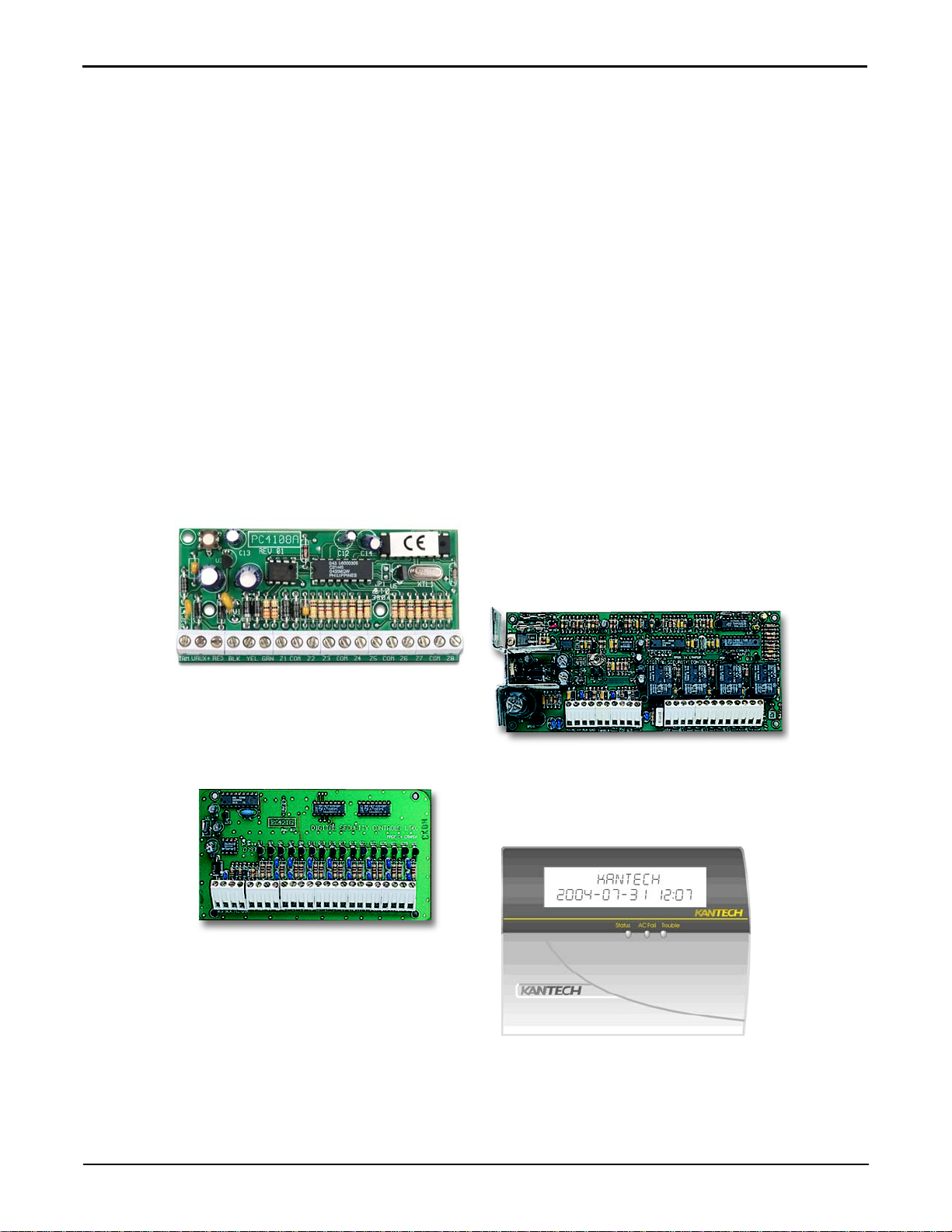
Built-in Combus Expansion
The KT-300 supports expansion modules to add inputs, outputs and an LCD time and date display for Time & Attendance purposes.
KT-PC4108 - 8-Zone Input
Expansion Module
KT-PC4216 - 16-Output
Expansion Module
KT-3LCD-LCD Time and Date Display
for Time & Attendance Functions
KT-PC4204 - 4-Relay and Combus
Additional Power Supply Module
DN1315-0707
3
Page 6

Technical Specifications
Specification Description
AC power 16VAC, 40VA, class 2 transformer
Battery back-up 1battery 12VDC, 7Ah, supervised, provides up to 12 hours of operation, Kantech BD7-12 battery tested for 4 hours
standby for UL294
Operating temperatures From 2°C to 40°C (35°F to 110°F)
Cabinet Dimensions (H-W-D) 29.9 cm x 28.8 cm x 7.7 cm (11-3/4” x 11-3/8” x 3”) EMT 1.9 cm (3/4”)
Cabinet Weight 2.4 kg (5.4 lbs)
PCB dimension 18.3 cm x 12.18 cm x 5.20 cm (7-1/4” x 4-3/4” x 2-1/16”)
Reader types Wiegand, proximity, bar code, magnetic, integrated keypad and others
Reader power output 12 VDC and 5VDC @ 175mA max, protected and supervised
Monitored points 8 monitored points, NO/NC, w/without EOL’s (expandable to 16), use UL recognized tamper switch on cabinet housing
to conform with UL 294
Points maximum wiring AWG #22 - 600 meters (2,000 feet)
Door strike power 12 V DC, 250mA max each, supervised
Auxiliary outputs 4 outputs, 25mA max each, open collector
Relay controlled output 2-relay controlled outputs, 25mA max each. Open collector to ground (use form “C” relays Kantech #KT-RM1 if
needed)
Auxiliary power output 11.5 to 13.85 VDC @ 175mA max, protected and supervised
Communication ports RS-232, RS-485 and Combus
Communication speed Up to 115.200 baud (automatic detection)
Firmware Flash memory 128 K
RAM memory 128 K (512 K unit available) Protected by a lithium battery
Network autonomy Distributed data and processing
Certifications / Listing CE, FCC, UL294 listed
4
DN1315-0707
Page 7

Electrical Specifications
VOLTAGE OUTPUTS MAXIMUM CURRENT ABSOLUTE COMBINED
Lock Outputs (12 VDC) 500 mA
Auxiliary Power (11.5 to 13.85 VDC) 175 mA
Reader 5 VDC and 12 VDC 175 mA
Combus 500 mA
Battery Charging (12 VDC) 250 mA 1.5 A
OPEN COLLECTOR OUTPUTS MAXIMUM CURRENT
LED (door 1 & 2) 25 mA (each)
Buzzer (Buz, door 1 & 2) 25 mA (each)
Controlled Relay 1 & 2 (RL1 & RL2) 25 mA (each)
KT-300 Door Controller Installation Manual
MAXIMUM
(250 mA each)
KT-300 Controller and Accessories
Kantech Model Description
KT-300/128K Door controller with 128K memory including KT-300CAB, KT-300ACC and KT-LOCK
KT-300/512K Door controller with 512K memory including KT-300CAB, KT-300ACC and KT-LOCK
KT-300PCB/128 KT-300/128K PCB only and KT-300 ACC
KT-300PCB/512 KT-300/512K PCB only and KT-300 ACC (not UL listed)
KT-300ACC Accessory kit including: 2 X 1.0k ohm, 10 x 5.6k ohm, 2 x 120 ohm, PCB standoffs, lock hole
cover, ground wire and screwdriver
KT-PC4108 8-zone input expansion module for KT-300
KT-PC4204 4-Relay and Combus additional power supply module for KT-300
KT-PC4216 16-Output expansion module for KT-300
KT-RM1 External isolation relay SPDT for KT-300 output (RL1/RL2) (not UL listed)
KT3-LCD Time & date LCD display unit for KT-300
KT-300CAB KT-300 black metal cabinet including KT- LOCK
KT-4051CAB Standard black metal cabinet for KT-PCxxx modules (order keylock separately)
KT-LOCK Keylock for KT-300CAB/KT-4051CAB metal cabinet (2keys/same as KT-200)
KT-TAMP Tamper switch for KT-300CAB/KT-4051CAB metal cabinet
TR1637W/CSA Transformer, Wire-in, 110V/16V (37VA) CSA (not UL listed)
TR1640P/CSA Transformer, Plug-in, 110V/16V (40VA) CSA (not UL listed)
TR1640P/UL Transformer, Plug-in, 110/16V (40VA) UL or DSC PTD1640 www.dsc.com
TR1640W-220 Transformer, Wire-in, 220V/16V (40VA) CE (not UL listed)
VC-485 or USB-485 Multi-function communication interface
DN1315-0707
5
Page 8

Installing the KT-300
Physical Installation
Check for ideal indoor location.
Stay away from electrical or communication devices.
The KT-300 Controller cabinet has been designed to be mounted on a wall without any additional enclosures. The cabinet is large enough to
accommodate the battery backup supply and the necessary wiring connections for most applications. EMT (Electrical Metallic Tubing)
conduit knockouts are provided in 2.2 cm (7/8”) on all sides of the cabinet.
The cabinet should be mounted indoors, in a secure location providing normal temperature and humidity, leaving 23 cm (8”) clear space
around all sides and a minimum of 33 cm (13”) clear space in front of the cabinet. The location should be easily accessible for servicing the
equipment and it is recommended that controllers be located close to the controlled doors.
Controllers must be located at a minimum distance of 2 m (6 feet) from any high voltage equipment or wiring and from electrical equipment
susceptible of generating electrical interference, at a minimum distance of 1 m (3 feet) from telephone equipment or lines, and at a minimum
of 8 m (25 feet) from any transmitting equipment.
Physical access, using keys, on controlled doors must be provided so that the KT-300 can easily be accessed for servicing in case of
malfunction.
Earth Grounding
AWG#18 grounding wire to EGND.
Since the KT-300 uses high performance communication, proper grounding must be provided to ensure proper operation.
An AWG#18 single conductor copper wire must be used to ground each controller to good earth ground as per the local
electrical code (be careful of ground loops). The ground clamp should be located below any other ground.
It is also recommended that you install an AWG#18 single conductor copper wire between each controller.
Door Locking Devices
Connect door locks to + and LK1- (+ and L2-)
Maximum 250mA @ 12 VDC per output
Check for local “magnetic lock” regulations
LK1-, LK2- and + terminals are located on the bottom left to the KT-300 terminal
strip. The locking device outputs are controlled according to the end-user
programmed parameters for allowing access to or unlocking doors according to
schedules and access levels. These door locking device outputs can operate DC
powered locking devices such as electromechanical strikes and can be configured
to operate fail-safe or fail-secure (normal or reverse action). Maximum DC current
for each lock output is 250 mA.
NOTE: Use 1K ohm EOL (End-Of-Line resistor) between + and LK- if not used.
This resistor is already included within the controller packaged box (KT300ACC).
WARNING: Controlled door locks may be governed by regulatory bodies and
should always be installed according to local regulations. In most
instances, there are strict limitations to installing fail-secure devices
and fail-safe locking devices such as magnetic locks or other similar
locking devices on doors used as emergency exits.
6
DN1315-0707
Page 9

Hooking Up Inputs
Connect devices to inputs 1 to 8.
Resistors (included with KT-300) for all
inputs 5.6K ohm (if selected).
The KT-300 has an on-board capability of
monitoring 8 input points (expandable to 16 if KTPC4108 module is used). Each input is
supervised with or without end-of-line resistors
(5.6K ohm). The maximum distance of one line is
600m (2,000 feet) with AWG#22.
NOTE: Inputs can be defined with: none or one
EOL (End-Of-Line) resistor according to
your EntraPass software settings.
Inputs 1-2 are automatically reserved for the first
controlled door. The contact is assigned input 1
and the associated request-to-exit detector as
input 2. Inputs 3 and 4 are automatically reserved
for the second controlled door. The contact is
assigned input 3 and the associated request-toexit detector as input 4. There is no obligation to
follow these rules but this standard convention
facilitates servicing.
KT-300 Door Controller Installation Manual
Readers and Keypads
READER CONNECTION TERMINAL WARNING
Connection the red wire lead (or power lead) of a 5 VDC reader to the
12 VDC terminal may damage the reader. See your reader installation
procedure for proper power connection.
Up to 2 readers can be connected to a KT-300. They can be installed
on one door to control both entry and exit or on two separate doors
operating independently to control one-way access.
The distance between the readers and the KT-300 controller varies by
reader type (please consult the installation manual for details).
Auxiliary outputs provide visual and/or audible access operation
feedback at the controlled door. Outputs “OUT DOOR 1 LED & BUZ”
are used for the first door and “OUT DOOR 2 LED & BUZ” are used for
the second door.
The 12 VDC auxiliary power can also be used to power low current
audible devices usually located at the controlled door.
Relay Controlled Outputs
Connect controlled outputs to low voltage devices (25 mA
max).
Add external relays for high voltage devices (optional - Kantech # KT-RM1).
The KT-300 provides two controlled outputs -RL1 & RL2 (open collector to ground-current limited to 25 mA). Use a KT-RM1 (optional) to
switch larger currents or voltages or to supply a dry contact.
Can be expanded up to 16 controlled outputs when using a KT-PC4216 module. This module allows a maximum of 16 outputs and a
maximum of up to 50 mA per output. SInce the KT-300 only supports 500 mA, a power supply module can be used to provide an additional
1 A to the Combus.
NOTE: If you are using a KT-PC4204 in “repower” mode and other KT-PC4216 modules that are assigned as relays 1-16 are also
connected to the same loop, do not use relay 1 of those modules or relay 1 of the KT-300 Door Controller (see the Combus
Repower section for more information).
DN1315-0707
7
Page 10

Auxiliary Outputs
Connect auxiliary outputs to readers and local warning devices.
Auxiliary outputs are used for visual and audible signals. They can be activated according to schedules, input conditions or events and local
alarms. Auxiliary outputs “OUT DOOR 1 & 2 LED” provide visual feedback of access operation, and auxiliary outputs “OUT DOOR 1 & 2
BUZ” can activate audible warning devices, such as T-REX, to signal door alarms.
Tamper Protection
Install tamper switch on cabinet (Kantech #KT-TAMP).
A tamper switch must be installed on the unit to detect unauthorized cabinet opening.
The normally closed tamper switch is connected to an input (choose an unused input (5 to 8) as tamper input or any other unused inputs on
the KT-PC4108 module (if used)).
NOTE: The tamper switch is required for a UL listed installation.
Connecting the KT-300
Connecting to the RS-485 Bus
Connect RS’485 cable to X1+, X1- and GND.
If not using VC-485 or USB-485: connect a 120 ohm end-of-line resistor on the first/last KT-300 (X- & X+).
If using VC-485 or USB-485: connect a 120 ohm end-of-line resistor on the last KT-300 only (X- & X+).
Controllers are linked together through their RS-485 connectors. The maximum communication loop length is 1.2 kilometers (4,000 feet)
using appropriate cabling. Connecting several KT-300 controllers at a single point is not acceptable nor are splitters or “spider web
networks.”
The RS-485 communication loop should be wired with Ethernet Category 3 double twisted pair network cable (see cable specifications
Belden 1227A, or equivalent). The RS-485 loop can operate from 1,200 to 115,200 bauds under normal conditions.
Intermittent communication problems or erratic operation may require network speed drops to 9,600 or 19,200 Bauds. Varying the network
speed does not perceptibly change the operation speed of the system. Usually, most installations should be set to 19,200 Bauds.
Important:
• Without a VC-485 or USB-485: Connect a 120 ohm end-of-line resistor between terminals X1- and X1+ of the first and last KT-
300.
• With a VC-485 or USB-485: connect a 120 ohm end-of-line resistor between terminals X1- and X1+ of the last KT -300. No need
to connect on the first KT-300 since the VC-485 contains an end-of-line resistor.
NOTE: To learn more about USB-485 wiring, refer to the USB-485 Installation Sheet, DN1482.
8
DN1315-0707
Page 11

KT-300 Door Controller Installation Manual
Connecting the Master Controller to the Host PC
Connect flat cable from KT-300 to the PC.
From 0 to 30m (0 to 100 feet) :
If the local master controller is located less than 30m (100
feet) from the host computer, use the on-board RS-232 RJ12
jack and the supplied flat cable.
From 30m to 60m (100 to 200 feet)
Since the master controller can be located up to 60m (200
feet) from the host computer, an extra 100 feet cable can be
added to the existing cable.
NOTE: If you plan to locate the host PC more than 30m (100
feet) away from the controller, be sure to use a VC485 interface. Otherwise, reduce the communication
speed to a minimum to avoid data loss.
From 60m to 1.2 km (200 to 4,000 feet)
If the master controller is located more than 60m (200 feet),
an optional VC-485 multi-function communication interface
must be used. It can also be used when running a
communication cable in areas unusually high in electrical
noise.
NOTE: The host computer is used to program the KT-300
Controllers.
RS-232 WITHOUT VC-485
KT-300
C
8
LED
OUTDOOR 1
RS-485 WITH VC-485
S/N
+5V
GND
READER PWR
+12V
X1+
RS485
X1-
VITAL
BUZ
LED
RL1
BUZ
OUTDOOR 2
An optional VC-485 must be used when the PC is located
more than 60m (200”) from the master controller
V+ = 5-14 VDC
DB25 (740-1012)
OR
DB9 (740-1022)
EGND
RJ12F
P3
RL2
VC-485
RS-232/RS-485
CONVERTER
CABLE DESCRIPTION: 1.2 METERS (4”)
AWG#26, 6 WIRES, INCLUDED WITH
VC-485. (MAX LENGTH 60 METERS (200”))
CBLK-20
MAX 60 M (200’)
ORANGE
ORANGE WHITE
BLUE
BLUE WHITE
RED
BLACK
DB9F
(740-1021)
CABLE DESCRIPTION: UNSHIELDED TWISTED PAIR
DATA CABLE, 24 GAUGE ETHERNET GRADE 3,
2 PAIR, BELDEN #1227A
KT-300
KT-300
TB1
+
LK1- LK2-
+12v-
16V
AC
LOCK 12V
AUX
DB25F
(740-1011)
+5V
TB2
WHT
+5V
READER PWR
+12V GND
ORANGE
X1+
ORANGE WHITE
BLUE
RS485
X1-
BLUE WHITE
EGND
*NOTE:
CONNECT A 120 OHMS END
OF LINE RESISTOR ON THE
LAST KT-300
Over Corporate Network (LAN)
If the master controller is used in a LAN-enabled corporate setting, use TCP/IP-to-RS-232
converter (such as the Kantech IP Link or the Lantronix UDS-1100 communication interface) to
connect the controller to the corporate network. This method uses existing wiring for data
exchange between EntraPass and the controllers. The diagram on the left shows how to connect a
DB-9 to RJ-12 flat cable between the master controller and the converter. Consult Application Note
DN1506 to learn how to set up the communication interface.
For remote sites
If the master controller is used in remote areas,
modems must be used to send and receive access
control data over telephone lines. For this application
Kantech supports US Robotics 56K external
Sportster modems at both ends of the communication
line. As shown on the right, a modem connects to the
master controller only using a DB25 to RJ-12 flat
cable. For dial-up communication settings via
software, refer to your communication settings.
EntraPass
Gateway
US Robotics Sportster
External 56k
Part# DU-MODEM-HOS
Host Modem Dipswitch Settings
1, 2, 6 UP
(Optional Host Modem
to receive alarms only)
EntraPass Dial-Up Setup with KT-300
Phone
Jack
Phone
Jack
Phone Line
US Robotics Sportster
External 56k
Part# DU-MODEM-RS
Remote Modem Dipswitch Settings
1, 6 UP
Phone
Jack
VITAL
Adaptor modem
to KT-300 (DB-25)
Part #740-1035
Flat cable
Part #CAB-15
RJ12
CONNECTOR
KT-300 MASTER
DN1315-0707
9
Page 12

Powering the KT-300
BAT
Install 120 / 220VAC / 16VAC, 40 VA, class 2 transformer.
Place battery in cabinet.
Power the KT-300 controller.
The KT-300 Controller must be powered by a 16VAC/40VA class 2 wire-in or plug-in
transformer.
After you have completed all the necessary steps, you may power the KT-300 Controller.
Connect AC power and connect the battery. Once powered, check the VITAL LED status
indicator to determine the status of communication and other vital parameters. Consult the
troubleshooting section for VITAL LED behavior identification.
If the AC supply is removed, the 12 Volt 7 A/h led-type backup battery will support normal
operation for up to 12 hours if fully charged. Internal battery verification will cutoff battery
power if the battery voltage level falls below 9.5 Volts.
NOTE: The KT-300 Controller will not start on battery alone.
NOTE: Power should only be applied to the unit when all connections are completed and
tested.
Installing Combus Modules
120 / 220 VOLTS 40VA
CLASS 2 (WIRE-IN)
RED
BLACK
SEALED RECHARGEABLE
12 VOLT
12 V BATTERY
7Ah MAXIMUM
TB1
BATTERY
7 AMP/h
16V
AC
AC LED
KT-300
LK1-+LK2-
+12v-
AUX
KANTECH PART #
KT-BD7-12
RED BLK YEL
LOCK 12V
PLUG-IN ALSO AVAILABLE
DO NOT CONNECT TO
RECEPTACLE CONTROLLED
BY A SWITCH
COMBUS
GRN
Introduction to Combus Modules
The Combus terminals on the KT-300 Controller are used to connect expansion modules to add more inputs, outputs, relays and LCD time
and date display. The four Combus terminals of the main panel must be connected to the four Combus terminals or wires of all modules.
Four expansion modules can be connected to KT-300’ s Combus (more specifications on each of these modules can be found later on in this
document.):
• KT-PC4108 - 8-Zone input expansion module
• KT-PC4204 - 4-Relay/Power supply expansion module
• KT-PC4216 - 16-Zone output expansion module
• KT3-LCD - Kantech LCD keypad module
Combus Specifications
The Combus provides 500 mA at 12 Volts (13.85 VDC). The recommended cable is #22
AWG. Each loop (module to KT-300) cannot exceed 300 m (1,000 feet) and the total
maximum cable length of all connected loops cannot exceed 1,200 m (4,000 feet).
For example:
• Only four wireruns at 1,000 feet from the KT-300.
• Only eight wireruns at 500 feet from the KT-300.
• Only ten wireruns at 400 feet from the KT-300
Shielded wire should only be used in areas with excessive RF noise of electromagnetic
interference. Modules can be straight run, connected in a daisy chain or T-tapped anywhere
on the Combus.
Keep in mind that the new modules must be defined in the EntraPass system when they are added to the Combus. Refer to the Controller
Definition section in the EntraPass Reference Manual to learn how to assign modules to your system.
10
DN1315-0707
Page 13

KT-300 Door Controller Installation Manual
Combus Repower (If Required)
Depending on how many modules are connected to the Combus
and how far they are from the KT-300 controller , you may need to
“repower” the controller’s Combus.
The Combus needs to be “repowered” if the voltage drops below
12.5 Volts between black and red wires of the last module of each
loop (the modules will still operate but there will be no
communication between the modules and the controller and a
“Combus module defect” event will be generated from the
controller). This voltage drops if modules are drawing too much
current (500mA maximum for the Combus of each KT-300).
Verify this voltage with a multi meter , and determine if you need to
install a KT-PC4204 in “repower” mode. Using this configuration,
you will be provided with an additional 1 amp of current on the
controller’s Combus. The KT-PC4204 is generally installed at the
beginning of the loop.
When using the KT-PC4204 in “repower” mode, the first relay of
the module will be reserved for the “repower function”. You will
have to assign an “all valid” schedule to the first relay so it is
“always activated” (refer to the Controller definition section of your
EntraPass User Reference Manual for the exact procedure.)
If you are using a KT-PC4204 in “repower” mode and other KTPC4204 modules that are assigned as relays 1-4 or KT-PC4216 modules that are assigned as relays 1-16 are also connected to the same
loop, do not use relay 1 of those modules or relay 1 of the KT-300 door controller. Please also note that all KT-PC4204 modules that are
used for Combus repower should be assigned as relays 1-4.
NOTE: Jumper 1 “J1” on the KT-PC4204 must be moved to the Combus relay position.
NOTE: Do not use any power supply other than the KT-PC4204 to repower the Combus. In the event of a power surge or transient, a
module may lock up and cease to communicate with the controller. If the KT-300 loses communication with the module, it will
initiate a module reset and will power down the Combus for five seconds in an attempt to reset the problem module. After five
seconds, the controller will reapply power to the Combus and the problem module should begin to operate as intended.
Module Housing Cabinet
Kantech Part: KT-4051CAB
Measurement: 16.8” H x 10.4” W 4.1” D (42,5cm H x 26.4 cm W x 10.4 cm D)
Color: Black
Cabinet will hold either:
• One KT-PC4204 power supply/relay module with batteries and one KT-PC4108/KTPC4216.
• Three KT-PC4216/KT-PC4108 modules
DN1315-0707
11
Page 14

KT-PC4108 - 8-Zone Input Expansion Module
KT-PC4108 Introduction
The KT-PC4108 module is a zone input module that adds up to 8 fully
programmable zones to the KT-300 Controller.
KT-PC4108 Specifications
• Connects to the controller via 4-wire Combus
• Current draw: 30 mA (from Combus)
• Supports single end-of-line and no end-of-line (5600 ohm resistors) zone loops
• AUX+ output: 12 VDC, 250 mA max. (drawn from Combus)
• Tamper contact input
Unpacking the KT-PC4108 Module
The KT-PC4108 package includes the following parts:
• One KT-PC4108 circuit board
• 16 end-of-line resistors (5600 ohm)
• Four plastic standoffs
Mounting the KT-PC4108 Module
The KT-PC4108 module should be located inside a compatible cabinet (Kantech
part no. KT-4105 CAB), mounted in a dry, secure location. Preferably, it should be
placed at a convenient distance from the connected devices.
Perform the following steps to mount the unit:
1. Press the four plastic standoffs through the mounting holes on the back of the cabinet.
2. Secure the cabinet to the wall in the desired location. Use appropriate wall anchors when securing the cabinet to drywall, plaster, concrete, brick or any other surfaces.
3. Press the circuit board into the four plastic standoffs to secure the unit to the cabinet.
NOTE: Wiring may take place once the unit is mounted.
Installation and Wiring
Before wiring the unit, ensure that all power sources (AC transformer and battery) are disconnected from the controller. Perform the
following steps to complete wiring:
1. Connect the four Combus wires to the KT-PC4108. Connect the Red, Black, Yellow and Green Combus wires to the RED, BLK, YEL and GRN terminals, respectively.
2. Complete all zone wiring to the zone input terminals (Z1-Z8).
3. Connect the external tamper switch, if used.
NOTE: Consult the wiring diagram above for further information.
Applying Power
After wiring is completed, apply power to the controller. Connect the battery leads to the battery, then connect the AC transformer.
NOTE: Do not connect the power until all wiring is completed.
Assigning the Module
Once all wiring is completed, the module must be assigned to the system. To assign the module, perform the following steps:
1. Establish communication between EntraPass and controller.
2. Remove the tamper switch wire.
3. A serial number should be displayed on screen. In the same window where the serial number is located, you should see the type of module and on which controller it is connected.
4. From the EntraPass user interface, go to the Controller definition menu and select the functionality of the module and enter the serial
number in the appropriate field (refer to Chapter 4, Defining Devices of your EntraPass Reference Manuel for more details).
NOTE: Do not forget to reconnect the tamper switch (or the wire, if there is no tamper switch).
12
DN1315-0707
Page 15

KT-300 Door Controller Installation Manual
KT-PC4204 - 4-Relay and Additional Power Supply Module
KT-PC4204 Introduction
The KT-PC4204 module is an output module with four programmable
relays. This module can be used to “repower” the Combus. The KTPC4204 can also be used for elevator control.
NOTE: Do not use any power supply other than the KT-PC4204 module
to repower the Combus. If a power supply other than the KTPC4204 is used, the Combus repower function will not operate
as intended.
KT-PC4204 Specifications
• Current draw: 30 mA (from Combus)
• 40 VA 16 VAC transformer required.
• Maximum 7 A/h battery required
• Connects to the controller via 4-wire Combus
• Four programmable relay contacts rated 2 A, 30 VDC
• AUX current: 1.0 A max.
• Tamper contact input
• Can be used to repower the Combus
Unpacking the KT-PC4204
The KT-PC4204 package should include the following parts/items:
• One KT-PC4204 circuit board
• One ground wire assembly
• Five plastic standoffs
• One 5 A replacement fuse
Mounting the KT-PC4204
The KT-PC4204 should be located inside a compatible cabinet (Kantech
part no. KT-4051CAB), mounted in a dry, secure location. Preferably, it
should be placed at a convenient distance from the connected devices.
Perform the following steps to mount the unit:
1. Push the five plastic standoffs through the mounting holes on the back of the cabinet.
2. Secure the cabinet to the wall in the desired location. Use appropriate wall anchors when securing the cabinet to dry wall, plaster, concrete, brick or other surfaces.
3. Press the circuit board into the plastic standoffs to secure the module to the cabinet.
NOTE: Wiring may take place once the unit is mounted.
Installation and Wiring
Before wiring the unit, ensure that all power (AC transformer and battery) is disconnected from the KT-300 controller. Perform the following
steps to complete wiring:
1. Connect the four Combus wires to the KT-PC4204. Connect the red, black, yellow and green Co mbus wires to the RED, BLK, YEL a nd GRN terminal respectively.
2. If the module is used for Combus Repower, connect the Combus wires according to the diagram on the right. Note that for this option, Jumper J1 must also be set to “Combus Relay”.
3. Complete all output wiring.
4. Connect the external tamper switch, if used.
Applying Power
After wiring is completed, apply power to the KT-300. Connect the battery leads to the battery, and connect the AC transformer. Then,
connect power to the KT-PC4204; the battery leads followed by the AC transformer.
NOTE: Do not connect the power until all wiring is complete.
DN1315-0707
13
Page 16

Assigning the KT-PC4204 Module
Once wiring is completed, the module must be assigned to the system. To assign the module, perform the following:
1. Establish communication between the PC and the controller.
2. Remove the tamper switch wire (or only the wire if tamper switch is not used).
3. A serial number should be displayed in the EntraPass message desktop. Look for the type of module and the controller to which it is connected.
4. From the EntraPass controller definition window, select the functionality of the module and enter the serial number in the appropriate field (refer to Chapter 4, Defining Devices or your EntraPass Reference Manual for more details).
5. If the module is used in “repower” mode, assign an “Always valid” schedule to relay 1 and assign the module’s functionality to “relay 1 to 4” in the EntraPass software.
NOTE: Do not forget to reconnect the tamper switch (or the wire, if there is no tamper switch).
NOTE: Ensure that Jumper J1 is set to “Combus Relay” position if used as “repower”.
KT-PC4216 - 16-Zone Output Expansion Module
KT-PC4216 Introduction
The KT-PC4216 module is an open-collector to 12 VDC 16-zone output module. Can be used for elevator access control (may require
additional hardware).
KT-PC4216 Specifications
• 16-output low current module, 12 VDC, 50 mA max. each, power drawn from Combus (since
Combus can handle a maximum of 500 mA, a KT-PC4204 module in “repower” mode can be used
to increase the current of the Combus of 1A).
• Connects to KT-300 via 4-wire Combus
• Nominal current draw of 15 mA
• Tamper contact input
• Can be used for elevator control
Unpacking the KT-PC4216
The KT-PC4216 package should include the following parts:
• One KT-PC4216 circuit board
• 4 plastic standoffs
Mounting the KT-PC4216
The KT-PC4216 should be located inside a compatible cabinet (part no. KT-4501CAB), mounted in a
dry, secure location. It should be placed at a convenient distance from the connected devices. Perform
the following steps to mount the units:
1. Press the four plastic standoffs through the mounting holes at the back of the cabinet.
2. Secure the cabinet to the wall in the desired location. Use appropriate wall anchors when securing the cabinet to drywall, plaster, concrete, brick or other surfaces.
3. Press the circuit board into the plastic standoffs to secure the module to the cabinet.
Wiring bay be started once the unit is mounted.
Installation and Wiring
Before beginning to wire the unit, ensure that all power (AC transformer and battery) is disconnected
from the controller. Perform the following steps to complete wiring:
1. Connect the four Combus wires to the KT-PC4216. Connect the Red, Black, Yellow and Green Combus wires to the RED, BLK, YEL and GRN terminals, respectively.
2. Complete all output wiring as illustrated on the next page.
3. Connect the external tamper switch, if used.
14
DN1315-0707
Page 17

KT-300 Door Controller Installation Manual
NOTE: Power is drawn from the
Combus. May require a
KT-PC4204 power
supply module if drawing
too much power from the
Combus.
Applying Power
1. After all wiring is completed, apply power to the KT-300.
2. Connect the battery leads to the battery.
3. Then, connect the AC transformer.
NOTE: Do not connect the power until all wiring is completed.
Assigning the KT-PC4216 Module
Follow the Instructions below for assigning and programming your KT-PC4216 module.
1. Establish communication between EntraPass and the controller.
2. Remove the tamper switch wire (or only the wire if tamper switch is not used).
3. A serial number, the type of module and on which controller it is connected should be displayed on the screen.
4. From the EntraPass user interface, go to the controller definition window and select the functionality of the module and enter the serial
number in the appropriate field (refer to Chapter 4, Defining Devices of your EntraPass Reference Manuel for more details).
NOTE: Do not forget to reconnect the tamper switch (or the wire, if there is no tamper switch).
NOTE: If you are using a KT-PC4204 in “repower” mode on the same loop, do not use the first relay of the KT-PC4216.
KT3-LCD - Kantech LCD Time & Date Display Module
KT3-LCD Introduction
The KT3-LCD module is an LCD readout module with integrated keypad which
provides date and time via a 32-character liquid crystal display.
KT3-LCD Specifications
• Connects to control panel via 4-wire Combus
• Current draw: 50 mA (from Combus)
• Input status (green), AC Fail (red) and Trouble (yellow) status lights
Unpacking the KT3-LCD
The KT3-LCD package includes the following parts/items:
• One KT3-LCD keypad
• Four mounting screws
Mounting the KT3-LCD
The keypad should be mounted where it is accessible to designated points to entry/exit. Once a dry and secure location is selected, perform
the following steps to mount the keypad:
1. Remove the keypad back plate by loosening the screw located at the base of the unit.
2. Secure the keypad back plate to the wall in the desired location. Use the included screws.
DN1315-0707
15
Page 18

Wiring the KT3-LCD
Before beginning to wire the unit, ensure that all power (AC transformer and battery) is
disconnected from the control panel.
To complete keypad wiring, connect the four Combus wires (Red, Black, Yellow and Green) to
keypad terminals R,B,Y and G.
Applying Power
1. Once all wiring is completed, turn the controller on.
2. Connect the battery leads to the battery.
3. Connect the AC transformer.
NOTE: Do not connect the power until all wiring is completed.
Assigning the KT3-LCD Keypad
Once all wiring is completed, the module must be assigned to the system. To assign the module, perform the following steps:
1. Establish communication between EntraPass and the controller.
2. Press the pound key (#) on each keypad. A serial number should be displayed in the EntraPass message desktop. Look for the type of module and the controller to which it is connected.
3. From the EntraPass controller definition window, select the functionality of the KT3-LCD and enter the serial number in the appropriate field (refer to Chapter 4, Defining Devices of the EntraPass Reference Manual for more details).
Troubleshooting Communication Problems
Default Initialization
The KT-300 default initialization is done at Kantech. The following steps should only be followed if:
a You are using a KT-300 from another site and there is no communication;
b The KT-300 was communicating via the RS-232 port and you installed a VC-485 to communicate via the
RS-485 port;
c You were using the KT-300 at a local site and now want to configure it for remote operation.
How to Use the Default Initialization (Hard Reset)
1. Disconnect both transformer and battery.
2. Remove all connection to DOOR1 and RL1 terminals.
3. Place a jumper between the DOOR1 and RL1 terminals.
4. Apply AC power to the transformer. The VITAL LED should flash 4 times. This means that the controller is in the initialization mode.
5. Remove jumper.
6. The VITAL LED will flash 3 beats at a time as soon as the controller communicates with the PC.
7. Reconnect the battery.
VITAL LED status indications
RL2
BUZ
OUTDOOR 2
LED
BUZ RL1
OUTDOOR 1
LED
8
C
7
6
AUX INPUTS
C
5
REX
2
C
DOOR
REX
1 DOOR
C
DOOR
Communication status and other vital controller parameters can be obtained from VITAL LED pulsations. This
information is particularly useful when connecting the controller to the rest of the access control system. Consult the
KT-300 Controller Wiring Diagram on page18 to locate the VITAL LED. The following table lists all conditions along with a brief description
.
VITAL LED Pulse Status Identification
1 per second Communication with EntraPass Global Gateway
2 per second Communication with master controller, modem online
3 per second Communication with EntraPass Corporate Gateway
4 per second Hard reset to factory defaults
Continuous Offline
0.5 second ON Reading access card
2.5 seconds ON Modem confirm
JUMPER
16
DN1315-0707
Page 19

KT-300 Door Controller Installation Manual
KT-300 Controller Maintenance Recommendations
The KT-300 circuit board includes a lithium battery (see the KT-300 Controller Wiring Diagram on page 18). This battery must be replaced
by a Kantech technician to avoid any risk of explosion. If the lithium battery stops working, return the circuit board to Kantech. Do not crush,
puncture, open, disassemble or otherwise mechanically interfere with the battery. Do not try to recharge the battery. If you need to dispose
of the circuit board and/or the lithium battery, wrap the KT-300 in non-conductive tape. Check with your local authorities for battery disposal
regulations.
WARNING: Do not store the batteries in such a way that they come into contact with each other or with any piece of metal. Explosion or
fire may occur. Should fire occur, use only dry chemical fire extinguishers. Do not use water to put out the fire. Do not heat
the batteries. Do not dispose of the batteries or circuit board in a fire. Do not disassemble the batteries. Do not apply
pressure to or deform the batteries. Ensure that the above precautions are strictly observed by related departments,
including, but not limited to, production, sales and outside contractors.
Regarding the recommended battery 7 A/12 V: It is the end-user and/or installer responsibility to assure that the disposal of used batteries is
made according to the waste recovery and recycling regulations currently applicable in their area. Use the recommended battery type
ONLY.
It is highly recommended to test the KT-300 Controller by performing the following tests:
1) Bi-annual test for battery:
Remove AC power from the controller and connect the battery to the controller for one hour. This test will ensure that in the event of a power
failure, the battery will be able to support normal operations. This test should be performed twice a year. Once the test has been performed
successfully, reconnect AC power to the controller.
2) Annual test for emergency lithium battery:
Measure voltage of lithium battery when power is totally removed from the controller (AC & DC power). To ensure maximum operation and
prevent loss of power, contact your distributor to return the KT-300 for maintenance if the lithium battery voltage measures below 2.5 VDC.
DN1315-0707
17
Page 20

KT-300 Wiring Diagram (North America Version)
(DATA0)
(DATA1)
(COMMON)
(POWER)
(BUZZER)
(LED)
BROWN
BLUE
RED (+12V)
BLACK
WHITE
GREEN
GRNWHTWHT GRN
TB2
KT300
ACCESS CONTROLLER
1
KANTECH SYSTEMS
U6
1
U7
WITH VC-485: ONLY TO
TO TERMINALS X1+ AND X1-
CONNECT A 120 OHMS
END OF LINE RESISTOR
*
READ1 READ2
+5VGND
IOPROX P325KP READER
THE LAST CONTROLLER
WITHOUT VC-485: FIRST
AND LAST KT-300
*
READER PWR
X1+
BAT
AC
CONTROLLER OR VC-485 AND LAST KT-300
CONNECT TO THE COMPUTER
60 METERS (200 FEET)
ENTRAPASS IF LESS THAN
USING
RS-232C
TO OTHER(S) CONTROLLER(S)
RS-485 NETWORK, ETHERNET CABLE
CATEGORY 3, UNSHIELDED, 4 CONDUCTORS
UP TO 1200 METERS (4000')
FROM THE FIRST AND LAST KT-300
WHITE
BLUE
WHITE
ORANGE
RS485
X1- +12V
EGND
RS232C
LED
VITAL
LED
*
2
1
5
TM
078
634
9
POLARIS
POLARIS 2KP READER
(LED)
(COMMON)
(POWER)
(DATA0)
(DATA1)
BROWN
BLUE (BUZZER)
RED (+5V)
BUZLEDLED BUZREXCBLK YEL GRN
WHITE
OUT DOOR 2
BLACK
NOTE: ONLY A SINGLE READER
FORMAT CAN BE SUPPORTED BY
EACH CONTROLLER. EXAMPLES
SHOWN HERE ARE ONLY TO
REPRESENT THE TYPICAL
CONNECTIONS FOR A WIEGAND
AND CLOCK & DATA INTERFACE
READERS.
WASHE R
NUT
NUT
KANTECH
SUPPLIED BY
OPEN
COLLECTOR
25mA MAX
WASHE R
CABINET
NOTE: ALL POWER OUTPUTS
ARE CURRENT LIMITED
BOLT
NCCOM
RELAY
NO
12 VOLTS DC
LOCAL RELAY
EARTH GROUND
KANTECH PART #
KT-RM1 (OPTIONAL)
GREEN
P3
+12V AUX
OUT DOOR 1
8567C
DOOR1 2 AUX. INPUTS
REX
DOOR
GREEN
NO OR NC
DRY CONTACT
7C
NC
CONTROLLER DEFINED
WITHOUT END OF LINE RESISTOR
C
NO
5600 5600
7
RESISTOR
NC DRY CONTACT
CONTROLLER DEFINED
WITH SINGLE END OF LINE
RESISTOR
NO DRY CONTACT
CONTROLLER DEFINED
WITH SINGLE END OF LINE
YELLOW
BLACK
COMBUS
LOCK 12V
AUXAC
RED
COMBUS EXPANSION
MODULES
DOOR CONTACT
120/240 VOLTS AC
REQUEST TO EXIT
TO RECEPTACLE
NOTE: DO NOT CONNECT
PLUG-IN ALSO AVAILABLE
CONTROLLED BY A SWITCH
16VAC, 40VA, CLASS 2, WIRE-IN
MOTION DETECTOR/SWITCH
RED
BLACK
IF NOT USED
DOOR LOCKING DEVICE
12 VOLTS DC 250 mA MAX.
CONNECT A 1000 OHMS RESISTOR
7 AMP/HR
BATTERY
SEALED RECHARGEABLE
7A/H
KT-BD7-12
12V BATTERY
12 VOLT
KANTECH PART #
RED C C
+
LK1- LK2- DOOR
+12V-
16V RL1 RL2
TB1
18
DN1315-0707
Page 21

KT-300 Wiring Diagram (UE Version)
KT-300 Door Controller Installation Manual
(DATA0)
(DATA1)
(COMMON)
BLACK
WHITE
GREEN
KT300
ACCESS CONTROLLER
(POWER)
(BUZZER)
(LED)
BROWN
BLUE
RED (+12V)
TB2
GRN
WHT
CONNECT A 120 OHMS
END OF LINE RESISTOR
WITH VC-485: ONLY TO
TO TERMINALS X1+ AND X1-
*
READ1 READ2
WHT
GRN
IOPROX P325KP READER
TO OTHER(S) CONTROLLER(S)
RS-485 NETWORK, ETHERNET CABLE
CATEGORY 3, UNSHIELDED, 4 CONDUCTORS
UP TO 1200 METERS (4000')
THE LAST CONTROLLER
WITHOUT VC-485: FIRST
AND LAST KT-300
ORANGE
WHITE
WHITE
*
READER PWR
+5VGND
X1+
FROM THE FIRST AND LAST KT-300
CONTROLLER OR VC-485 AND LAST KT-300
GREEN WIRE TO GROUND CONNECTION
BLUE
RS485
X1- +12V
EGND
LED
VITAL
CONNECT TO THE WORKSTATION (ENTRAPASS
V3.0) IF LESS THAN 60 METERS (200 FEET)
NOTE: ONLY A SINGLE READER FORMAT CAN BE SUPPORTED
BY EACH CONTROLLER. EXAMPLES SHOWN HERE ARE ONLY
TO REPRESENT THE TYPICAL CONNECTIONS FOR A WIEGAND
USING
RS232C
AND CLOCK & DATA INTERFACE READERS.
RS-232C
P3
BUZLEDLED BUZREXCBLK YEL GRN
(DATA0)
GREEN
OUT DOOR 2OUT DOOR 1
(DATA1)
WHITE
*
(COMMON)
(POWER)
RED (+5V)
BLACK
2
1
3
(LED)
BROWN
BLUE (BUZZER)
TM
098
654
7
POLARIS
25mA MAX
OPEN COLLECTOR
+12V AUX
NOTE: ALL POWER OUTPUTS
7C
NC
POLARIS 2KP READER
NC
COM
RELAY
NO
12 VOLTS DC LOCAL RELAY
KANTECH PART #KT-RM1 (OPTIONAL)
ARE CURRENT LIMITED
RESISTOR
NC DRY CONTACT
CONTROLLER DEFINED
WITH SINGLE END OF LINE
1
KANTECH SYSTEMS
U6
1
U7
8567C
2 AUX. INPUTS
REX
DOOR
DOOR
1
REQUEST TO EXIT
MOTION DETECTOR/SWITCH
GREEN
YELLOW
COMBUS
RED C C
+
LOCK 12V
LK1- LK2- DOOR
BAT
AC
LED
AUX
+12V-
AC
16V RL1 RL2
TB1
BLACK
RED
C
NO
7
NO OR NC
DRY CONTACT
CONTROLLER DEFINED
WITHOUT END OF LINE RESISTOR
DOOR CONTACT
COMBUS EXPANSION
MODULES
7 AMP/HR
5600 5600
RESISTOR
NO DRY CONTACT
CONTROLLER DEFINED
WITH SINGLE END OF LINE
IF NOT USED
DOOR LOCKING DEVICE
12 VOLTS DC 500 mA MAX.
CONNECT A 1000 OHMS RESISTOR
AC DC
POWER SUPPLY
AC
+DC
AC
BAT+
-
EARTH GROUND
12 VDC 1 AMP
POWER SUPPLY
DOOR LOCKING DEVICE
GREEN WIRE TO KT300
EGND CONNECTION
250 VAC
FUSE 20mm
315mA SLOBLOW
BATTERY
SEALED RECHARGEABLE
12 VOLT
RED
BLACK
12V BATTERY 7A/H
KANTECH PART #KT-BD7-12
240 VAC IN
16VAC 80VA OUT
TRANSFORMER
MAINS
NEUTRAL
LIVE
240 VAC
50 HERTZ
DN1315-0707
19
Page 22

20
DN1315-0707
 Loading...