

Page 1

Page 2

2
Contents
TYCO INTERNATIONAL LTD END-USER LICENSE AGREEMENT 3
Pre-Installation Notes 7
Technical Support 9
Overview of Features 11
Wiring Charts 17
System Architecture 21
LED Patterns 23
Installation, Connection & Power 27
Reset & Configuration 38
KT-1 Models, Expansion Kits & Related Items 46
Compliance Specifications 47
©Copyright, 2016, all rights reserved
Page 3

3
TYCO INTERNATIONAL LTD
END-USER LICENSE AGREEMENT
FOR KANTECH Software Provided With or Without Products or Components
IMPORTANT - READ CAREFULLY
KANTECH Software purchased with or without Products and Components is copyrighted and is purchased under the following license terms:
• This End-User License Agreement (“EULA”) is a legal agreement between You (the company, individual
or entity who acquired the Software and any related Hardware)and KANTECH, the manufacturer of
the integrated security systems and the developer of the software and any related products or components (“HARDWARE”) which You acquired.
• If the KANTECH software product (“SOFTWARE PRODUCT” or “SOFTWARE”) is intended to be accompanied by HARDWARE, and is NOT accompanied by new HARDWARE, You may not use, copy or install
the SOFTWARE PRODUCT. The SOFTWARE PRODUCT includes computer software, and may include
associated media, printed materials, and “online”or electronic documentation.
• Any software provided along with the SOFTWARE PRODUCT that is associated with a separate enduser license agreement islicensed to You under the terms of that license agreement.
• By installing, copying, downloading, storing, accessing or otherwise using the SOFTWARE PRODUCT,
You agree unconditionally to be bound by the terms of this EULA, even if this EULA is deemed to be a
modification of any previous arrangement or contract. If You do not agree to the terms of this EULA,
KANTECH is unwilling to license the SOFTWARE PRODUCT to You, and You have no right to use it.
SOFTWARE PRODUCT LICENSE
a - The SOFTWARE PRODUCT is protected by copyright laws and international copyright treaties, as well
as other intellectual property laws and treaties. The SOFTWARE PRODUCT is licensed, not sold.
1 - GRANT OF LICENSE - This EULA grants You the following rights:
a - Software Installation and Use - For each license You acquire, You may have only one copy of the
SOFTWARE PRODUCT installed.
b - Storage/Network Use - The SOFTWARE PRODUCT may not be installed, accessed, displayed, run,
shared or used concurrently on or from different computers, including a workstation, terminal or
other digitalelectronic device (“Device”). In other words, if You have several workstations, You will
have to acquire a license for each workstation where the SOFTWARE will be used.
c - Backup Copy - You may make back-up copies of the SOFTWARE PRODUCT, but You may only have
one copy per license installed at any given time. You may use the back-up copy solely for archivalpurposes. Except as expressly provided in this EULA, You may not otherwise make copies of the
SOFTWARE PRODUCT, including the printed materials accompanying the SOFTWARE.
2 - DESCRIPTION OF OTHER RIGHTS AND LIMITATIONS
a - Limitations on Reverse Engineering, Decompilation and Disassembly - You may not reverse engineer,
decompile, or disassemble the SOFTWARE PRODUCT, except and only to the extent that such
© Copyright, 2016, allrights reserved
Page 4

activity is expressly permitted by applicable law notwithstanding this limitation. You may not make
any changes or modifications to the Software, without the written permission of an officer of
KANTECH. You may not remove any proprietary notices, marks or labels from the Software Product.
You shall institute reasonable measures to ensure compliance with the terms and conditions of this
EULA.
b - Separation of Components - The SOFTWARE PRODUCT is licensed as a single product. Its component
parts may not be separated for use on more than one HARDWARE unit.
c - Single INTEGRATED PRODUCT - If You acquired this SOFTWARE with HARDWARE, then the SOFTWARE
PRODUCT is licensed with the HARDWARE as a single integrated product. In this case, the SOFTWARE
PRODUCT may only be used with the HARDWARE as set forth in this EULA.
d - Rental - You may not rent, lease or lend the SOFTWARE PRODUCT. You may not make it available to
others or post it on a server or web site.
e - Software Product Transfer - You may transfer all of Your rights under this EULA only as part of a per-
manent sale or transfer of the HARDWARE, provided You retain no copies, You transfer allof the
SOFTWARE PRODUCT (including allcomponent parts, the media and printed materials, any upgrades
and this EULA), and provided the recipient agrees to the terms of this EULA. If the SOFTWARE
PRODUCT is an upgrade, any transfer must also include all prior versions of the SOFTWARE
PRODUCT.
f - Termination - Without prejudice to any other rights, KANTECH may terminate this EULA if You fail to
comply with the terms and conditions of this EULA. In such event, You must destroy all copies of the
SOFTWARE PRODUCT and all of its component parts.
g - Trademarks - This EULA does not grant You any rights in connection with any trademarks or service
marks of KANTECH or its suppliers.
3 - COPYRIGHT
Alltitle and intellectual property rights in and to the SOFTWARE PRODUCT (including but not limited
to any images, photographs, and text incorporated into the SOFTWARE PRODUCT), the accompanying printed materials, and any copies of the SOFTWARE PRODUCT, are owned by KANTECH or its
suppliers. You may not copy the printed materials accompanying the SOFTWARE PRODUCT. Alltitle
and intellectual property rights in and to the content, which may be accessed through use of the
SOFTWARE PRODUCT, are the property of the respective content owner and may be protected by
applicable copyright or other intellectual property laws and treaties. ThisEULA grants You no rights
to use such content. Allrights not expressly granted under this EULA are reserved by KANTECH and
its suppliers.
4 - EXPORT RESTRICTIONS
You agree that You will not export or re-export the SOFTWARE PRODUCT to any country, person, or
entity subject to US export restrictions.
5 - CHOICE OF LAW
This Software License Agreement is governed by the laws of the State of New York.
6 - LIMITED WARRANTY
a - NO WARRANTY
©Copyright, 2016, all rights reserved
4
Page 5

KANTECH PROVIDES THE SOFTWARE “AS IS” WITHOUT WARRANTY. KANTECH DOES NOT WARRANT
THAT THE SOFTWARE WILLMEET YOUR REQUIREMENTS OR THAT OPERATION OF THE SOFTWARE WILL
BE UNINTERRUPTED OR ERROR-FREE.
b - CHANGES IN OPERATING ENVIRONMENT
KANTECH shall not be responsible for problems caused by changes in the operating characteristics of
the HARDWARE, or for problems in the interaction of the SOFTWARE PRODUCT with non-KANTECH
SOFTWARE or HARDWARE PRODUCTS.
c - LIMITATION OF LIABILITY; WARRANTY REFLECTS ALLOCATION OF RISK
IN ANY EVENT, IF ANY STATUTE IMPLIES WARRANTIES OR CONDITIONS NOT IN THIS LICENSE
AGREEMENT, KANTECH'S ENTIRE LIABILITY UNDER ANY PROVISION OF THIS LICENSE AGREEMENT
SHALL BE LIMITED TO THE GREATER OF THE AMOUNT ACTUALLY PAID BY YOU TO LICENSE THE
SOFTWARE PRODUCT AND FIVE US DOLLARS (USD$5.00). BECAUSE SOME JURISDICTIONS DO NOT
ALLOWTHE EXCLUSION OR LIMITATION OF LIABILITY FOR CONSEQUENTIAL OR INCIDENTAL
DAMAGES, THE ABOVE LIMITATION MAY NOT APPLYTO YOU.
d - DISCLAIMER OF WARRANTIES
THIS WARRANTY CONTAINS THE ENTIRE WARRANTY AND SHALLBE IN LIEU OF ANY AND ALL OTHER
WARRANTIES, WHETHER EXPRESSED OR IMPLIED (INCLUDING ALL IMPLIED WARRANTIES OF
MERCHANTABILITY OR FITNESS FOR A PARTICULAR PURPOSE) AND OF ALLOTHER OBLIGATIONS OR
LIABILITIES ON THE PART OF KANTECH. KANTECH MAKES NO OTHER WARRANTIES. KANTECH
NEITHER ASSUMES NOR AUTHORIZES ANY OTHER PERSON PURPORTING TO ACT ON ITS BEHALF TO
MODIFY OR TO CHANGE THIS WARRANTY, NOR TO ASSUME FOR IT ANY OTHER WARRANTY OR
LIABILITY CONCERNING THIS SOFTWARE PRODUCT.
e - EXCLUSIVE REMEDY AND LIMITATION OF WARRANTY
UNDER NO CIRCUMSTANCES SHALL KANTECH BE LIABLE FOR ANY SPECIAL, INCIDENTAL,
CONSEQUENTIAL OR INDIRECT DAMAGES BASED UPON BREACH OF WARRANTY, BREACH OF
CONTRACT, NEGLIGENCE, STRICT LIABILITY, OR ANY OTHER LEGALTHEORY. SUCH DAMAGES
INCLUDE, BUT ARE NOT LIMITED TO, LOSS OF PROFITS, LOSS OF THE SOFTWARE PRODUCT OR ANY
ASSOCIATED EQUIPMENT, COST OF CAPITAL, COST OF SUBSTITUTE OR REPLACEMENT EQUIPMENT,
FACILITIES OR SERVICES, DOWN TIME, PURCHASERS TIME, THE CLAIMS OF THIRD PARTIES,
INCLUDING CUSTOMERS, AND INJURY TO PROPERTY.
WARNING: KANTECH recommends that the entire system be completely tested on a regular basis.
However, despite frequent testing, and due to, but not limited to, criminal tampering or electrical
disruption, it is possible for this SOFTWARE PRODUCT to fail to perform as expected.
© Copyright, 2016, allrights reserved
5
Page 6

6
©Copyright, 2016, all rights reserved
Page 7

7
Pre-Installation Notes
Copyright Information
Copyright © 2016 Tyco International Ltd. and its Respective Companies. All Rights
Reserved. All specifications were current as of publication date and are subject to
change without prior notice. EntraPass, Kantech and the Kantech logo are trademarks of Tyco International Ltd. and its Respective Companies.
Safety Information
IMPORTANT: NEVER INSTALL THE EQUIPMENT DURING AN ELECTRICAL STORM.
WARNING: DO NOT LOOK DIRECTLY AT LED WITH UNSHIELED EYES: DAMAGE TO
RETINA MAY OCCUR.
The KT-1 One-Door Controller shall be installed and used within an environment
that provides the pollution degree max 2, and over voltages category II NON
HAZARDOUS LOCATIONS, INDOOR only. The equipment is FIXED and
PERMANENTLY CONNECTED. The KT-1 is designed to be installed by Service Persons only (service person is defined as a person having the appropriate technical
training and experience necessary to be aware of hazards to which that person may
be exposed in performing a task and of measures to minimize the risks to that person or other persons). The equipment is installed in a metallic cabinet that meets
the applicable requirements for a FIRE ENCLOSURE.
Note: When installed on the North American Market, powered via the
UL, cUL Listed 40VA Transformer, the KT-1 shall be connected to the
mains by a LICENSED ELECTRICIAN in accordance with the applicable
rules of the National Electrical Code or Canadian Electrical Code
regarding this type of connection.
1 - The connection to the mains supply must be made as per the local authorities
rules and regulations. An appropriate disconnect device must be provided as
part of the building installation. Where it is not possible to rely on the identification of the NEUTRAL in the AC MAINS SUPPLY, the disconnecting device
must disconnect both poles simultaneously (LINE and NEUTRAL).
2 - AVOID setting up the equipment near heaters, air conditioners, ventilators,
and/or refrigerators; DO NOT select a place that exposes your controller to direct sunlight, excessive heat, moisture, vapors, chemicals or dust.
© Copyright, 2016, allrights reserved
Page 8

3 - If during the installation a knockout on the cabinet is removed, it is the
installer's responsibility to ensure that the same degree of protection for the
cabinet is provided by the use of bushings, fittings, adequate sealant, etc.
4 - If a metallic cabinet is used, the cabinet must be secured to the building struc-
ture before operation. Use four (4) stainless steel tapping screws #8, 32 mm
(1.25 in) to mount the cabinet.
5 - The ground connection must be as shown within the included diagram, or equi-
valent.
6 - Internal wiring must be routed in a manner that prevents:
• Excessive strain on wire and on terminal connections;
• Loosening of terminal; connections;
• Damage of conductor insulation;
• Reducing the clearance between SELV (Safety Extra Low Voltage) circuits and NON-POWER Limited Circuits (Battery wires);
• Route the battery wires away from the rest of the SELV circuits.
7 - It is the end-user and/or installer's responsibility to ensure that the disposal of
the used batteries is made according to the waste recovery and recycling regulations applicable to the intended market.
8 - There are no serviceable parts within the equipment; For any issues regarding
the equipment please contact your installer.
9 - Before leaving the premises, the Ethernet communication lines must first be
connected to an approved (acceptable to local authorities) type Network Interface Device (NID), (UL installations, UL 60950 listed NID, for ULC installations
CAN/CSA C22.2, No. 60950-1 Certified NID). All wiring shall be performed
according to the local electrical codes.
10 - DISCONNECT POWER BEFORE SERVICING.
©Copyright, 2016, all rights reserved
8
Page 9

9
Technical Support
For technical assistance with this and other Kantech products, contact technical support, Monday to Friday. See the following table for the technical support phone
numbers.
Country/Region Phone Numbers Support Hours E-mail
North America Toll Free +1 888 222 1560 (GMT -05:00)
USA and Canada
Direct: +1450 444 2030
Fax: +1 450 4442029
8:00to 20:00
kantechsupport
@tycoint.com
Latin America (GMT -03:00)
Argentina
Direct: +5411 4711 8711
Fax: +54114711 8201
9:00to 18:00
ingenieria
@tycoint.com
Asia (GMT +08:00)
Asia Pacific Direct: +31 475352 722 8:30to 18:00
apac.support
@tycoint.com
Europe Toll Free +800 CALL TYCO /+ 800 2255 8926 (GMT +01:00)
Bahrain +800 04127
8:00to 18:00
emea-accesscontrol[email protected]
France +33 04 72 79 14 83
Greece +00 800 31 22 94 53
Russia +8 10 8002052 1031
Spain +900 10 19 45
Turkey +00 800 31 92 30 07
United Arab Emirates +800 0 310 7123
United Kingdom
+44 08701 ADT SUP/4408701
238 787
Direct: +31 475352 722
Fax: +31475 352 725
© Copyright, 2016, allrights reserved
Page 10

10
©Copyright, 2016, all rights reserved
Page 11

11
Overview of Features
The KT-1 One-Door Controller is designed to meet the highest standards of access
control and point monitoring applications.
The KT-1 is available in two configurations:
• KT-1 (single gang mount)
• KT-1-PCB
More information is available near the end of this guide on expansion kits and
related items.
KT-1
KT-1-PCB
© Copyright, 2016, allrights reserved
Page 12

Compatibility
The KT-1 is compatible with all EntraPass Editions v6.02 and higher:
• EntraPass Special Edition
• EntraPass Corporate Edition
• EntraPass Global Edition with a Multi-site Gateway, Global Gateway, or a KT-NCC
Network Communications Controller
IP Communication Configuration
Web Configuration Page: The Web Configuration Page can be used to verify and
configure the IP settings of the KT-1. Refer to the System Architecture section of
this guide for further details.
KT-Finder: The KT-Finder is a stand-alone application that can be used to verify and
configure the IP settings of the KT-1. Refer to the System Architecture section of
this guide for further details.
One Door/Two Readers (Entry/Exit)
The KT-1 is a full onboard door access controller.
Example of KT-1 Setup with T.REX
©Copyright, 2016, all rights reserved
12
Page 13

Communication Ports
• 1 10/100Base-T (ETH1) PoE+ for network connection with the EntraPass Gateway
• 1 RS-232 for communication and integration with third party systems (RS232 is
only available on the KT-1-PCB unit)
Note: For UL listed installations this is for supplementary use only.
• 1 RS-485 (COM1) for communication with EntraPass and/or loop of controllers
• 1 RS-485 (COM2) for future use
IP Connectivity With or Without PoE/PoE+
When used with EntraPass Special Edition, Global Edition and Multi-Site Gateway,
the KT-1 can gather its configuration through an IP connection over the LAN (Local
Area Network) and over the Internet for a WAN (Wide Area Network), (WAN configuration not recommended with Global Edition). In this mode, the 1st controller
becomes a “Master Controller” and can poll up to 31 Kantech controllers. The KT-1
is compatible with all the controllers. The KT-1 asynchronously polls the controllers
(KT-100, KT-300, KT-400) and communicates with the EntraPass Gateway, only
when necessary. This significantly reduces the amount of bandwidth required to
operate your security system on the network.
Note: The KT-100 is not ULlisted model, do not use in UL listed applications.
PoE will provide power for the unit up to 13W. PoE+ provides power for the unit
up to 27W. Use only PoE/PoE+ source or external power supply source to power
KT-1.
Compatible Tested PoE and PoE+ Switches
The following switches have been tested for use with the KT-1:
• Netgear FS108p (PoE)
• Altronix netway8 (PoE+)
• Trendnet TPE-T80 (PoE+)
• Trendnet TPE-105i (PoE+)
• Philong PoE36U-180-R or Poe125U-4-HP-R
The supervision of IP network connection between KT-1 and Entrapass is controlled
by the network pulse time. This feature is programmable in EntraPass between 15
second and 10 minutes. Default times are (1 minute for EntraPass CE and 15
© Copyright, 2016, allrights reserved
13
Page 14

seconds for EntraPass GE). For UL listed installations the allowed range for the heartbeat is 15 seconds to 140 seconds. The loss of communication notification will
occur when the network pulse time has elapsed twice plus 15 seconds.
Note: The KT-1 has been tested by UL with the PoE/PoE+ models Phihong POE36U1AT-R and/or the POE125U-4-HP-R. These devices shall be used in conjunction with
UL listed transient protectors. Other compatible PoE/PoE+ configurations may be
possible.
For UL listed installations use only in conjunction with compatible PoE/PoE+devices
that are UL294 listed. These devices shall be used in conjunction with UL listed Transient protectors.
AES Encryption 128-Bit
The KT-1 is extremely secure. It uses 128-bit AES encryption to communicate with
the Gateway, which prevents any hacking from the internet, and ensures secure
communications when used over the internet on a wide area network (WAN).
128-bit AES encryption has been validated by NIST (Certificate No. 3092).
Inputs
There are 4 onboard inputs that can be used for the following:
• Door contact
• T.Rex (Request to Exit Detector)
• Interlock
• External Alarm System Status (Armed/Disarmed)
• External Alarm System Alarm (Alarm/Secure)
• External Alarm System Zones
• To trigger relays in the event of an alarm
• Zone shunt: Single or group of zones can be permanently or temporarily
'shunted' to a secure state on the same controller. Shunt method includes:
• Zone Shunt by another Zone - When a zone in alarm is programmed to shunt
another zone/group of zones.
• Zone Shunt on Unlock - When a zone is temporarily frozen to its actual state
(alarm or secured) after an access granted.
• Manual Shunt - Operator can manually 'Shunt' a zone to a secure state.
©Copyright, 2016, all rights reserved
14
Page 15

• Disarmed Door Shunt - When alarm system is disarmed, some zones may be
'Shunted' to a secure state.
• Entry/Exit Delay Shunt - When a user is in the process of disarming/arming
the alarm system and entry/exit delay prevails, some zones may be
'Shunted' to a secure state.
• Arming/Disarming Request
• Postpone Arming Request
Tamper Switch
The screw at the bottom of the case, which locks the cover, is also used to identify
tampering of the KT-1 cabinet.
Lock Outputs
There are 2 supervised onboard lock outputs. The locking function can also be performed by any onboard relay configured for this functionality.
Note: Supervision is only provided to detect short-circuit fault, not open-circuit
fault.
Relay Outputs
The KT-1 has 2 open collector onboard switch to ground relay outputs.
The KT-1-PCB has 2 form C relays.
Reader Outputs
There are 4 different possible open collector, switch to ground, outputs. Reader outputs are used to give user visual and/or audible feedback on the ongoing access
events. The outputs consist of LEDs (LED, OUT1 and OUT2) and buzzer (BUZ).
Reader Interfaces
There are 2 onboard 12VDC reader interfaces. They can be programmed for Wiegand or ABA clock and data readers.
© Copyright, 2016, allrights reserved
15
Page 16

Integration Interface
The KT-1 supports alarm panel interfacing with the appropriate connections made
between zone inputs, relay outputs and the alarm system panel. The KT-1-PCB version also supports integration interfacing using RS-232 for fire alarm panel and intrusion integrations.
Note: RS-232 interface communication with fire alarm panel has not been evaluated by UL.
Automatic Port Detection
The KT-1 automatically detects the site communication speed set by EntraPass as
well as the communication port which can be IP (ETHERNET) or RS-485 (COM1).
Downloadable Firmware
The firmware program can be downloaded from any EntraPass workstation to the
KT-1. It is stored in the controller’s flash memory, and is upgraded without having to
change any parts.
Trouble and Reporting
The KT-1 continuously monitors its power and reports low and critical power issues.
Power outputs are monitored and electronically protected against short-circuits
and surges. Locking devices are also monitored for short and open circuits.
©Copyright, 2016, all rights reserved
16
Page 17
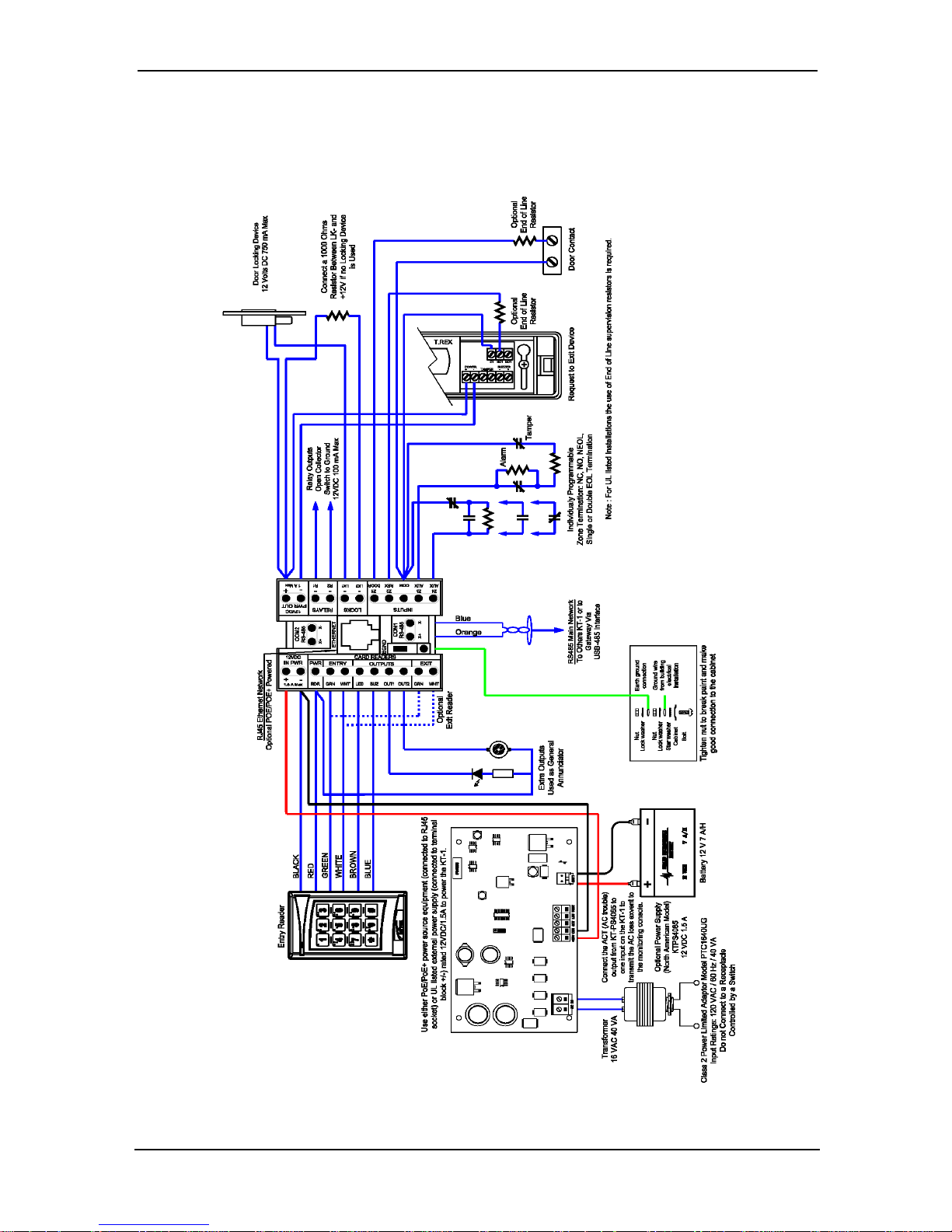
Wiring Charts
KT-1 Inputs and Outputs View
© Copyright, 2016, allrights reserved
17
Page 18
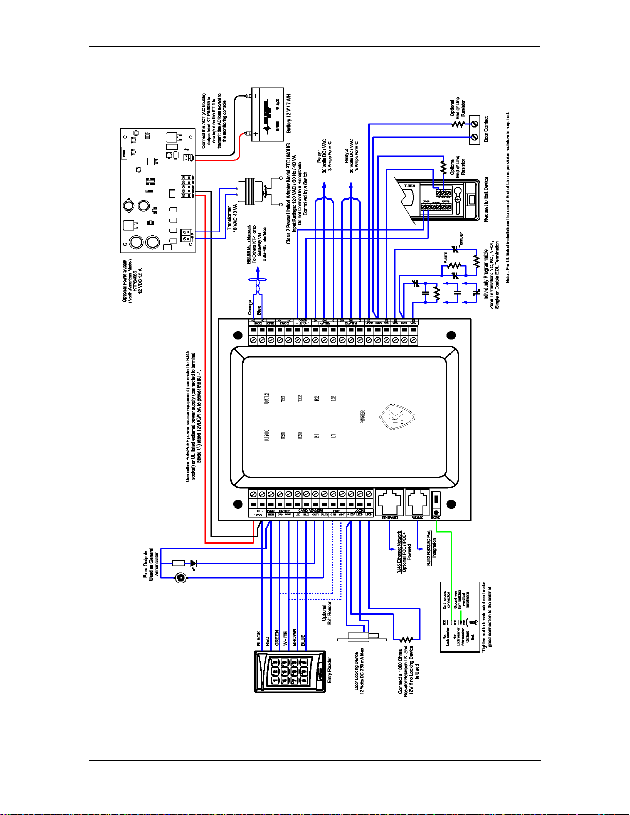
KT-1-PCB Inputs and Outputs View
©Copyright, 2016, all rights reserved
18
Page 19
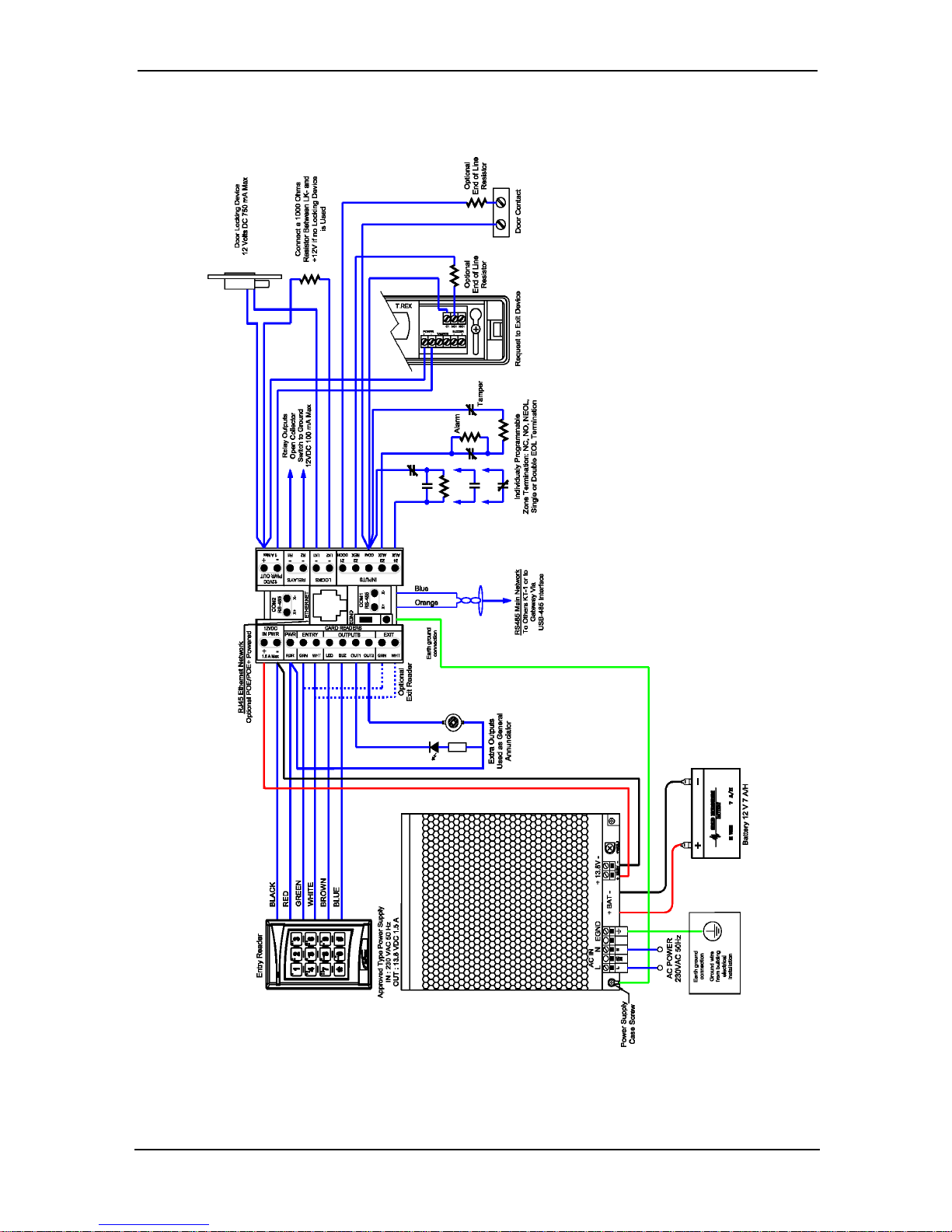
KT-1 EU Inputs and Outputs View
© Copyright, 2016, allrights reserved
19
Page 20
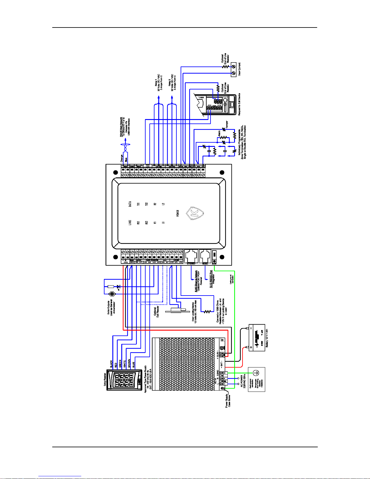
KT-1-PCB EU Inputs and Outputs View
©Copyright, 2016, all rights reserved
20
Page 21
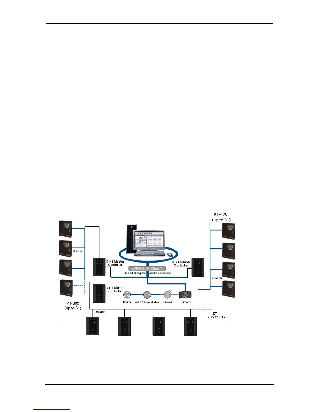
System Architecture
Configurations
The KT-1 can be used through various site configurations with EntraPass Special, Corporate and Global Editions. The following configurations are possible:
Applications with EntraPass Special, Corporate Multi-site Gateway and Global Edition Gateway:
• Over the internet.
• Over RS-485 with a USB-485 or VC-485.
Application with EntraPass Global Edition and a KT-NCC.
• Over the Internet on premises.
• Over RS-485 with a USB-485 or VC-485.
Layout examples of the configurations:
Over the Internet with EntraPass Special and Corporate Editions
with Multi-site Gateway
Note: KT-1 can be connected to EntraPass using either RS-485 bus (shown) or Eth-
ernet connection.
© Copyright, 2016, allrights reserved
21
Page 22
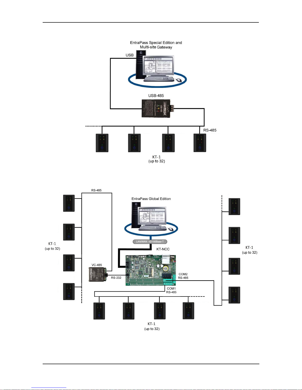
USB-485 with EntraPass Special, Corporate and Global Editions
Over the Internet with a KT-NCC and EntraPass Global Edition
©Copyright, 2016, all rights reserved
22
Page 23
LED Patterns
Visual Status Indicators (LEDs)
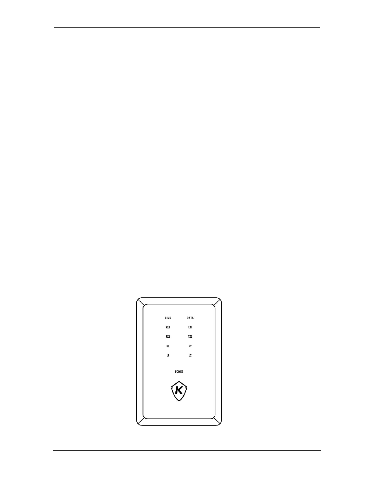
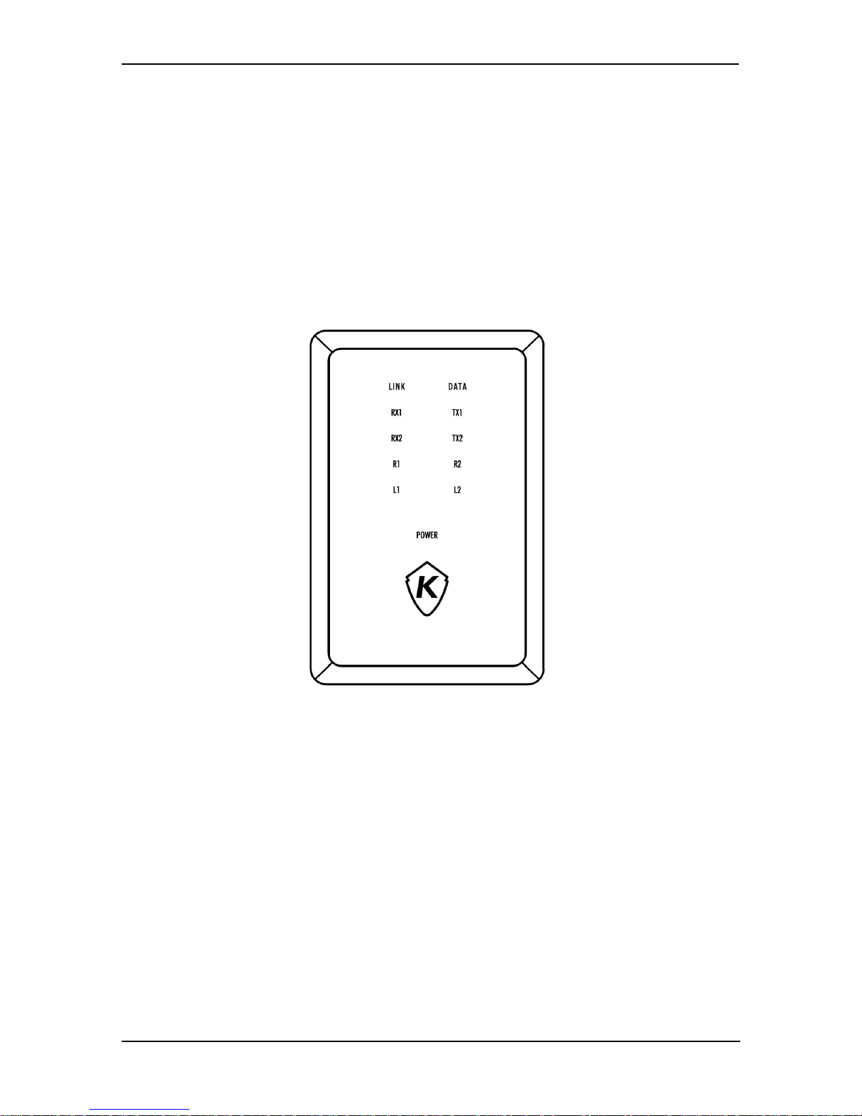
The front cover of the KT-1 controller has multiple LED status indicators, which are
used for such activities as troubleshooting, network activity, power status and outputs.
The LED status indicators, as illustrated on the cover diagram below, are as follows:
• LINK (Ethernet): The green LED is OFF when there is no Ethernet network or
the cable is disconnected, and the LED is ON when there is an Ethernet cable
and network connection.
• DATA (Ethernet): The yellow LED indicates network activity.
• RX1 and TX1: The yellow RS-485 serial port LEDs transmit (TX1) and receive
(RX1) activity between the KT-1and the gateway.
• RX2 and TX2: Future use.
• R1 (Relay 1) and R2 (Relay 2): Each output has a red LED indicator which turns
on each time the corresponding relay is activated.
• L1 (Lock 1) and L2 (Lock 2): Each lock output has a red indicator which turns on
each time the corresponding output is activated.
• POWER: The green DC power LED is ON when the DC level is sufficient for all DC
terminals, such as the 12V AUX. For further details, see the Troubleshooting &
Configuration section of this guide.
• Kantech Shield (The One Button): The blue LED indicates the communication
status with EntraPass or the IP mode of the controller.
© Copyright, 2016, allrights reserved
23
Page 24
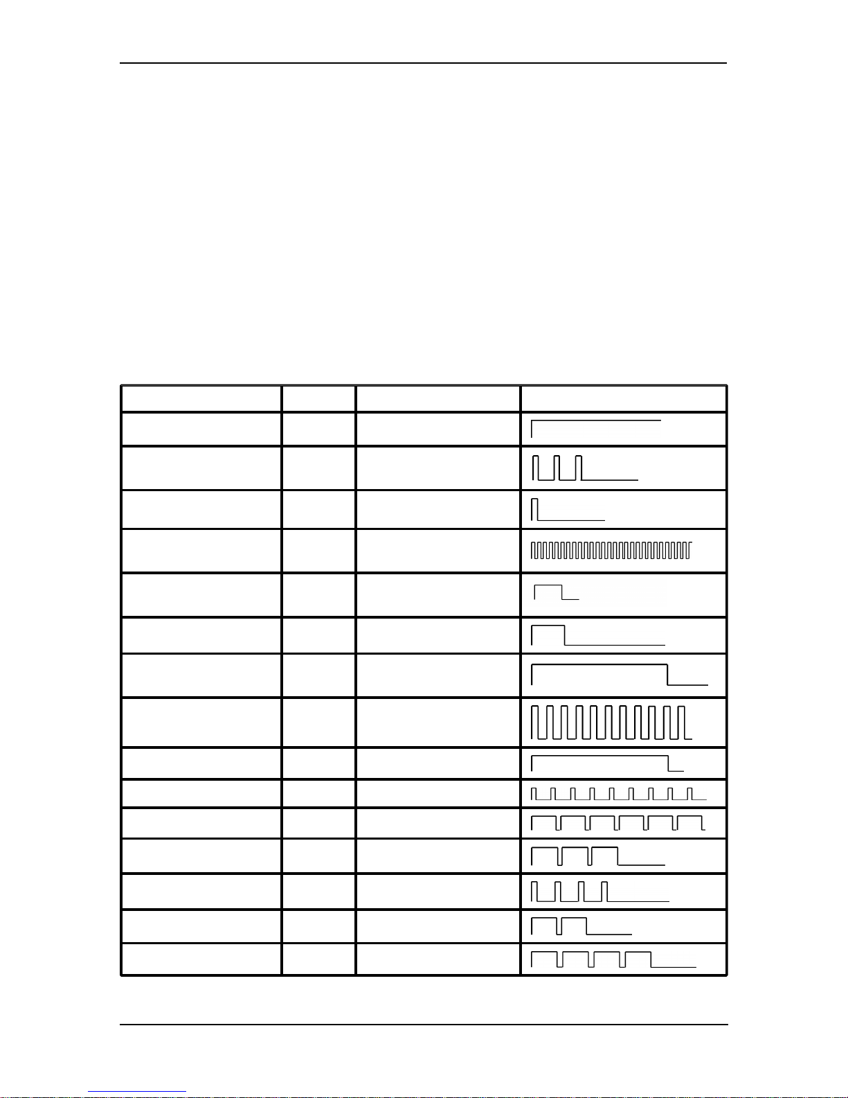
Heartbeat LED Patterns
Communication status and other vital controller parameters can be obtained from
heartbeat LED patterns located in the Kantech shield on the cover. This information
is particularly useful when connecting the controller to the rest of the EntraPass system. The following table lists all possible conditions, along with a brief description of
each. Refer to the Troubleshooting section of this guide if you must reset or change
the communication mode of the KT-1.
WARNING: DO NOT LOOK DIRECTLY AT LED WITH UNSHIELDED EYES, OR
DAMAGE TO RETINA MAY OCCUR.
LED Patterns Table
Mode Color Led Flashing Pattern
Booting Up Blue Steady
Corporate / Multi-site
Gateway
Blue 3 short pulses
Global Gateway Blue 1 short pulse
Rebooting Blue
10pulses / sec @ 50% duty
cycle
Card Read or Swipe Blue
Single 0.5 sec burst,
resume previous flash
During Enrollment White 1 long pulse (every 2 sec)
Enrollment
Acknowledge
Pink 2.5 sec Burst
Firmware Update Green
5 pulses/ sec @ 50% duty
cycle
Receive Broadcast Green Single 2.5 sec burst
FailSoft Yellow Continuous short pulses
Factory Default DHCP Yellow Continuous long pulse
Forced Default STATIC Yellow 3long pulses
Hard Reset Red 4 short pulses
Unableto Resolve DNS Red 2 long pulses
DHCP Server Failed Red 4 long pulses
©Copyright, 2016, all rights reserved
24
Page 25

Technical Specifications
Type Description
DC Power input
11.3VDC- 14VDC, 1.5A Note: Compatible with KT-PS4085
Power supply module. Recommended plug-in adapter model
PTC1640UG. Standby power: 12V/7Ah battery, provides 4h of
battery backup
PoE 13W, 1A *(See note below)
PoE+ 25.5W, 1.9A *(See note below)
Operating Temperatures
For UL listed installations: 0°C to 49°C (32°F to 120°F) indoor
use only For European compliant installations: -10°C to 55°C
(14°F to 131°F) Environmental Class II
Humidity Level 93% max. (relative humidity non-condensing)
Cabinet dimensions: KT-1
From wall surface (Width x Height x Thickness) 3.4” x 5.125”
x 1.81” (2.4” overall thickness)
Cabinet dimensions: KT-1PCB
4.78'' x 5.436'' x 1.863''
Weight: KT-1 10.75 ounces (305g)
Cabinet Weight: KT-1-PCB 13.93 ounces (395g)
Reader types
Wiegand, proximity, ABA Clock and Data, bar code, magnetic,
integrated keypad, smartcard and others
Reader power output 12 VDC 500 mA max, protected and supervised 룈
Monitored points (zone
inputs)
4 monitored points (Z1 to Z4), NO/NC without EOL (DRY),
single EOL, double EOL and 1 fixed-function tamper input
Points maximum wiring
AWG #22 - 600 m (2,000 ft)
For specifications for maximum wiring for readers, refer to
the associated installation manuals of the respective readers.
Door strike power supervised
750 mA for one output or 1.0 A total (in PoE 13W, 375 mA
each or 750 mA total).
Lock outputs can only detect short-circuit fault, not open-circuit fault.
Auxiliary reader outputs
LEDs (LED, OUT1 and OUT2) and buzzer (BUZ), 25mA max
each, open collector outputs
Relay controlled output:
KT-1
2 open collector outputs, 100 mA each
© Copyright, 2016, allrights reserved
25
Page 26

Relay controlled output:
KT-1-PCB
2 onboard form C relays, 30 VDC/VAC, 3 Amps each, 0.6
power factor
Communication ports:
KT-1
2 x RS-485, 1 x Ethernet 10/100 Base-T with RJ-45
Communication ports:
KT-1-PCB
1 x RS-232 with RJ-12, 2 x RS-485, 1 x Ethernet 10/100 BaseT with RJ-45.
Note: RS-232 is for supplementary use.
Auxiliary power 1.0 A max (shared with door strike power)
Communication speed
- 1200 to 115200 Bauds (automatic detection) over RS-485 10/100 Mb/s BaseT over Ethernet
Flash memory
256 MB NAND flash for application, storage and stand-alone
event buffer holding 20,000 events
RAM memory 128 MB DDR2 for application loading and running
Network autonomy Distributed data and processing
Certifications / Listing
USA: UL294, UL1076, FCC Part 15 Class B Canada: ICES-003
(B)/NMB-003 (B) Europe: EN60950-1, EN50130-4:2011,
EN61000-6-3. CE Compliance in accordance with applicable
LVD and EMC Directives. Australia/New Zealand: RCM Compliance
AES Encryption AES NIST Validation of certificate No. 3092
*Note: The KT-1 has been tested by UL with the PoE/PoE+ modles Phihong
POE36U-1AT-R and/or the POE125U-4-HP-R. These devices shall be used in conjunction with UL listed Transient protectors. Other compatible PoE/PoE+ configurations may be possible.
**Note: The KT-1 is capable of restarting automatically after total power loss, and
will keep the programming for an unlimited time of power interruption. The design
uses flash memory for saving access rules. For KT-1 and Class B installations
powered with a PoE device, it is recommended to use a ferrite on the Ethernet
cable. (P/N 10000089).
©Copyright, 2016, all rights reserved
26
Page 27

Installation, Connection & Power
Overview
Installation of the KT-1 varies with the type of unit: KT-1 or KT-1-PCB. Installation is
also dependent on the selection of the 12 V or PoE/PoE+ as the power source (see
Powering the KT-1 later in this section for more details).
Preparing to Install the KT-1
Locate an ideal indoor location for installation of the KT-1/KT-1-PCB while keeping
clear of electrical and communication devices. The KT-1 unit has been designed to
be mounted on a wall without any additional enclosures. The KT-1-PCB has been
designed to go into a cabinet.
The unit shall be mounted indoors in a secure location, providing normal temperature and humidity. There should be 23 cm (8 in) clear space around all sides,
and a minimum of 33 cm (13 in) clear space in front of the unit. The location should
be easily accessible for servicing the equipment and it is recommended that controllers be located close to the controlled doors.
Controllers must be located at a minimum distance of 2 m (6 ft) from any high
voltage equipment or wiring; electrical equipment susceptible of generating electrical interference; at a minimum distance of 1 m (3 ft) from telephone equipment
or lines; and at a minimum of 8 m (25 ft) from any transmitting equipment. Physical
access, using keys on controlled doors, must be provided so that the KT-1 can easily
be accessed for servicing in case of malfunction.
Physical Installation:
Warning: It is the INSTALLER’S RESPONSIBILITY to route and secure the internal
wiring in such a manner (using tie wraps or equivalent means for fixing the cables)
that no cable may become in contact with the FRONT COVER of the METAL
ENCLOSURE.
© Copyright, 2016, allrights reserved
27
Page 28
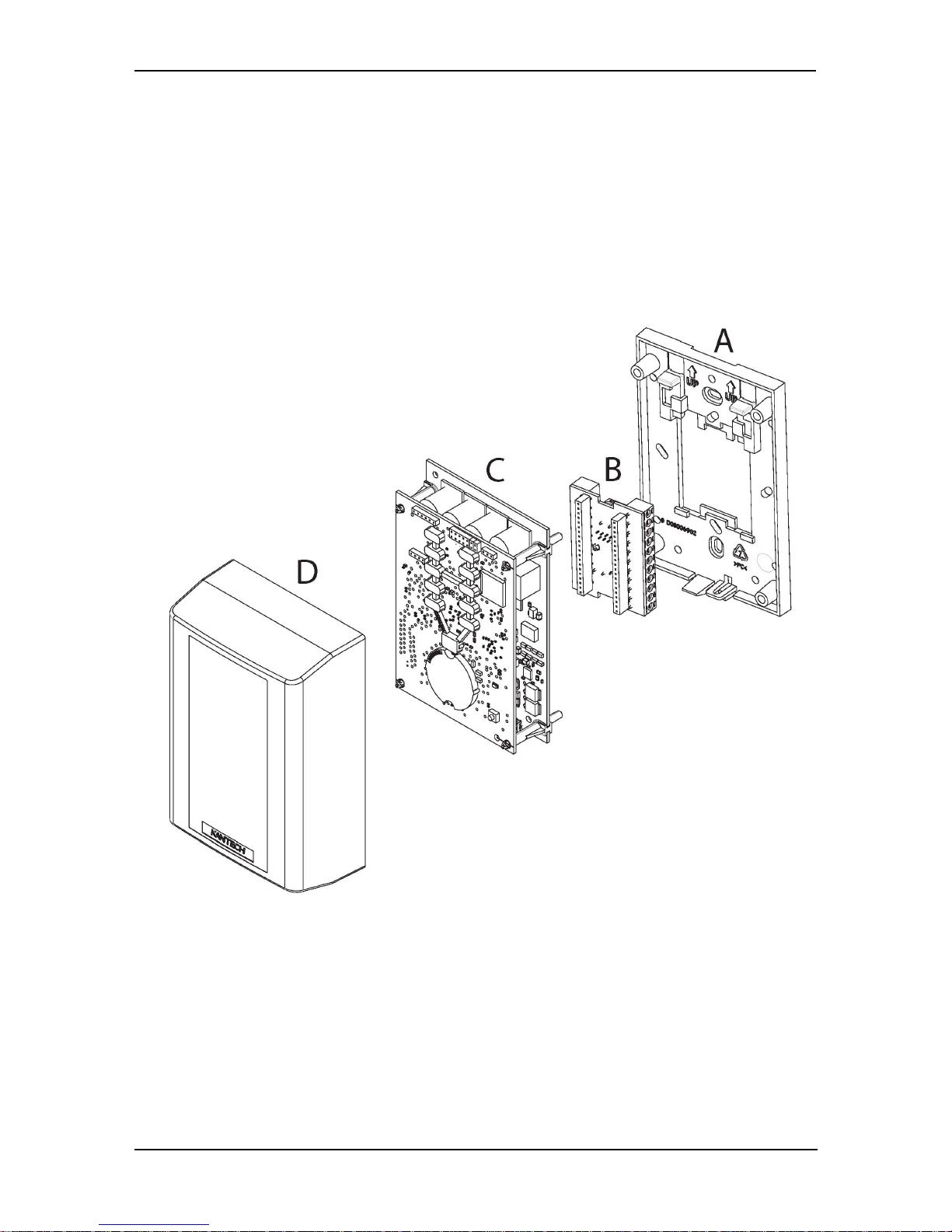
KT-1 Installation
1 - Complete each of the required connections on the small board (B) which
mounts on the wall-plate.
2 - Install the wall-plate (A) to the wall using the two Phillips screws provided.
3 - Clip board (B) on the wall plate (A).
4 - Mount the main boards (C) into board (B)
5 - Mount the cover (D) and secure with one of the Phillips screws provided.
©Copyright, 2016, all rights reserved
28
Page 29
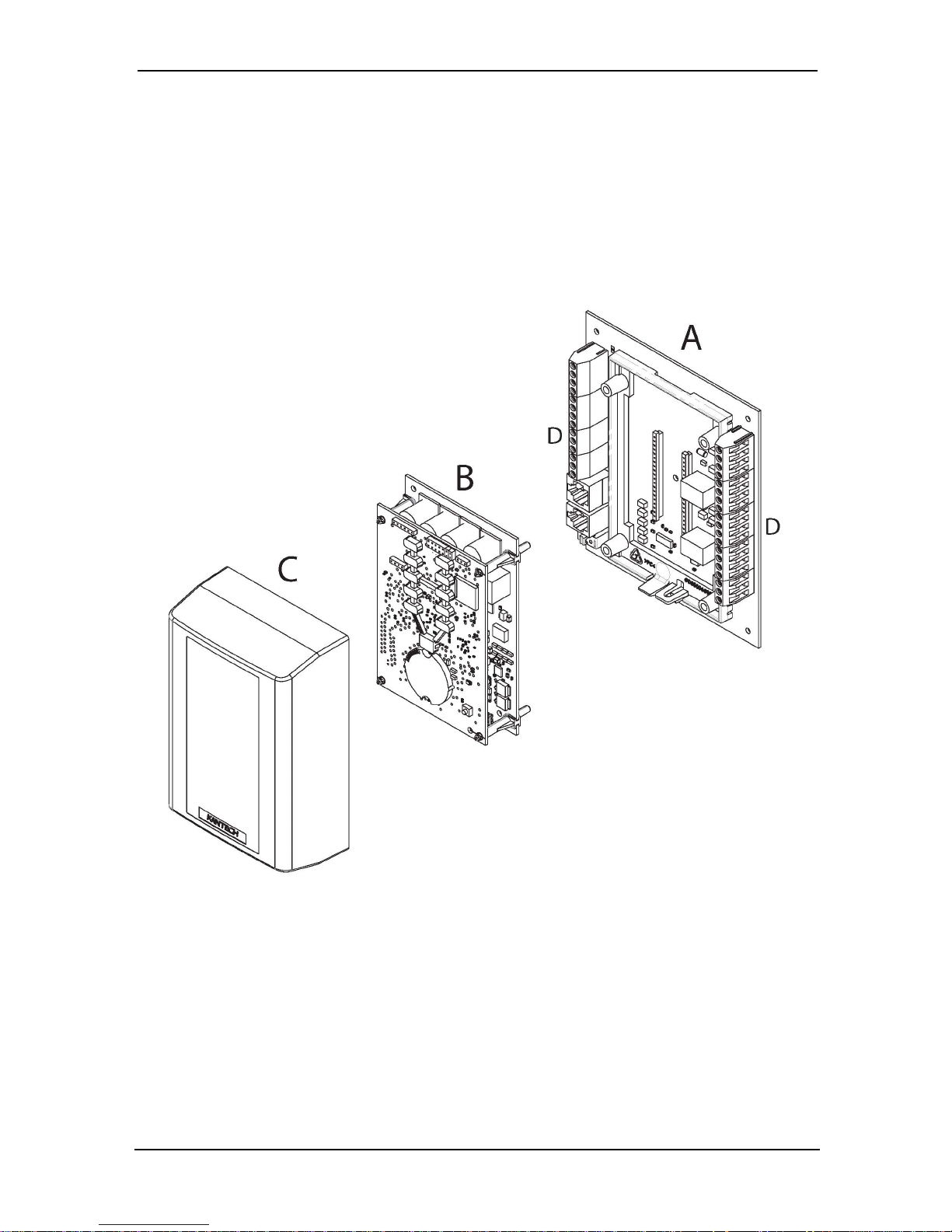
KT-1-PCB Installation
1 - Remove the IO boards from the cabinet (or leave the boards in place, but be
certain power is not connected).
2 - Complete each of the required connections before connecting the 12 VDC, or
if powered by ethernet, reconnect the PoE or PoE+ to the RJ-45 connection.
3 - Replace the boards in the cabinet (if previously removed at beginning of install-
ation).
Earth Grounding
The KT-1 uses high performance communication. Proper grounding must be
provided to ensure proper operation. Connect the ground wire to the green quickconnect terminal. Make an earth ground connection to the cabinet of the KT-1 controller as per the requirements of your local electrical code. Wire the E-GND terminal on the KT-1 printed circuit board directly to that connection point.
© Copyright, 2016, allrights reserved
29
Page 30
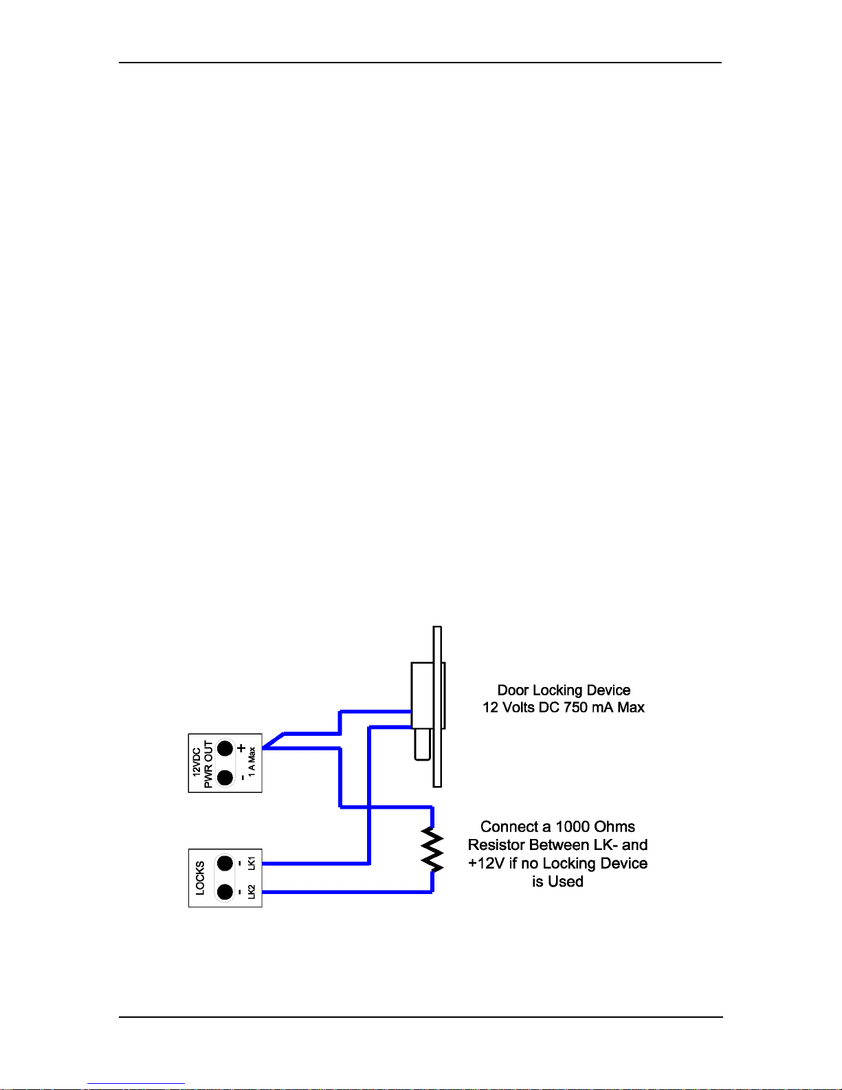
Door Locking Devices
Connect the door lock device to + and LK1- or + and LK2-, if needed. Check for local
“magnetic lock” regulations. The locking device outputs are controlled according to
the end-user programmed parameters for allowing access to or unlocking doors
according to schedules and access levels. These doors locking device outputs can
operate DC powered locking devices such as electromechanical strikes and can be
configured to operate fail-safe or fail-secure (normal or reverse action).
Note: If required, the KT-1 can provide galvanically isolated output(s) by programming any of the relays (KT-1-PCB only).
Note: Use 1 K ohm EOL (End-of-Line resistor) between + and LK- terminals if not
used.
To connect the door locking device:
1 - Connect the negative wire from the door strike to the LK1- output, and option-
ally, the door magnetic lock to the LK2- output.
2 - Connect the positive wire to the +12 VDC output.
Lock Set-up for KT-1
©Copyright, 2016, all rights reserved
30
Page 31
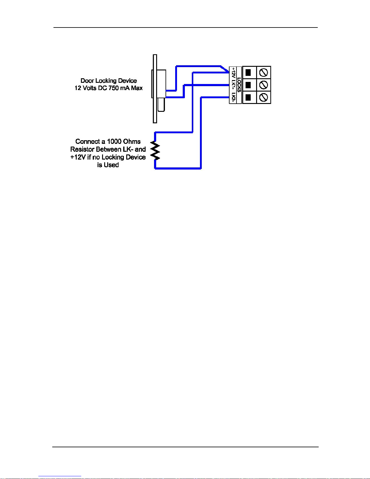
Lock Set-up for KT-1-PCB
Warning: Controlled door locks may be governed by regulatory bodies and always
be installed according to local regulations. In most instances, there are strict limitations to installing fail-secure devices and fail-safe locking devices such as magnetic locks or other similar locking devices on doors used as emergency exits.
Hooking Up Inputs
Connect devices to inputs 1 to 4. Resistors for all inputs are 5.6K ohm (if selected).
The KT-1 has an on-board capability of monitoring 4 input points. Each onboard
input is supervised with or without end-of-line resistors (5.6K ohm). The maximum
distance of one line is 600 m (2,000 ft) with AWG #22 in a single or double EOL configuration.
Note: Onboard Inputs can be defined with: none, single or double EOL (End-ofLine) resistor(s) according to your EntraPass software settings. For UL listed installations use of supervised EOLresistors is required.
Inputs 1-2 are automatically reserved for the controlled door. The door contact is
assigned to input 1 and the associated request-to-exit detector as input 2. There is
no obligation to follow these rules but this standard convention facilitates servicing.
© Copyright, 2016, allrights reserved
31
Page 32
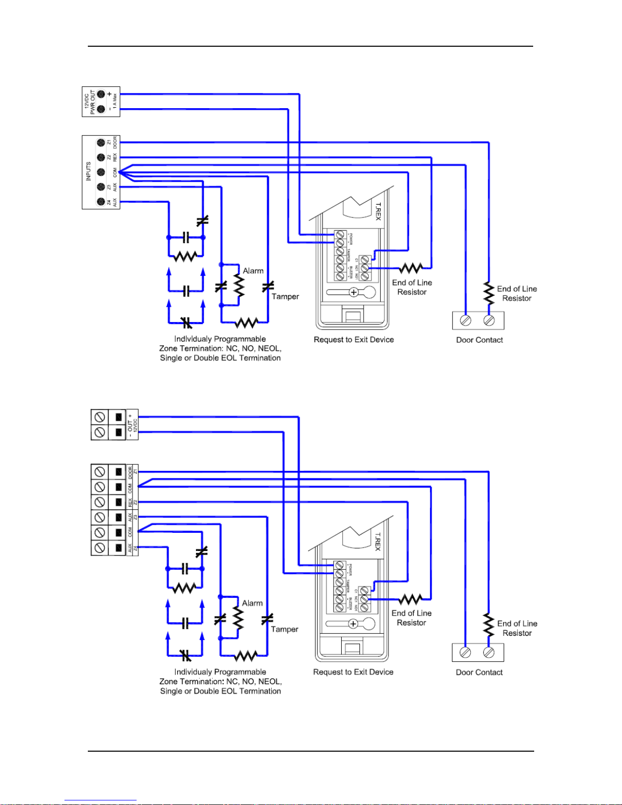
Inputs for KT-1
Inputs for KT-1-PCB
©Copyright, 2016, all rights reserved
32
Page 33
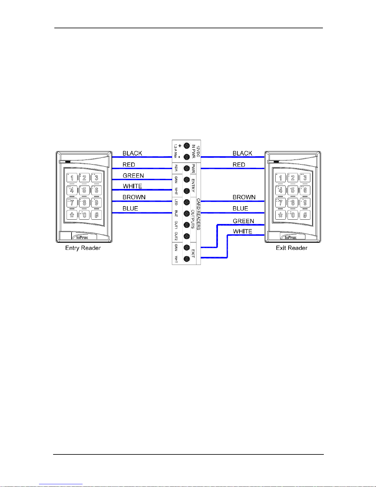
Connecting Reader Units
The KT-1 provides 12 VDC power for card readers. Up to 2 readers can be connected to a KT-1. The distance between the readers and the KT-1 varies by reader
type, please refer to the documentation provided with the reader. Auxiliary outputs
provide visual and/or audible access operation feedback at the controlled door.
One controller can be installed to control the entry of a single door, or two readers
can be installed on a single door and used to control both the entry and exit. Outputs OUT1 and OUT2 are extra multipurpose outputs.
Relay Controlled Outputs
The KT-1 provides two relay outputs: RELAY1 and RELAY2. These outputs are opencollector rated for up to 100 mA each. The KT-1-PCB provides two form C relays:
© Copyright, 2016, allrights reserved
33
Page 34
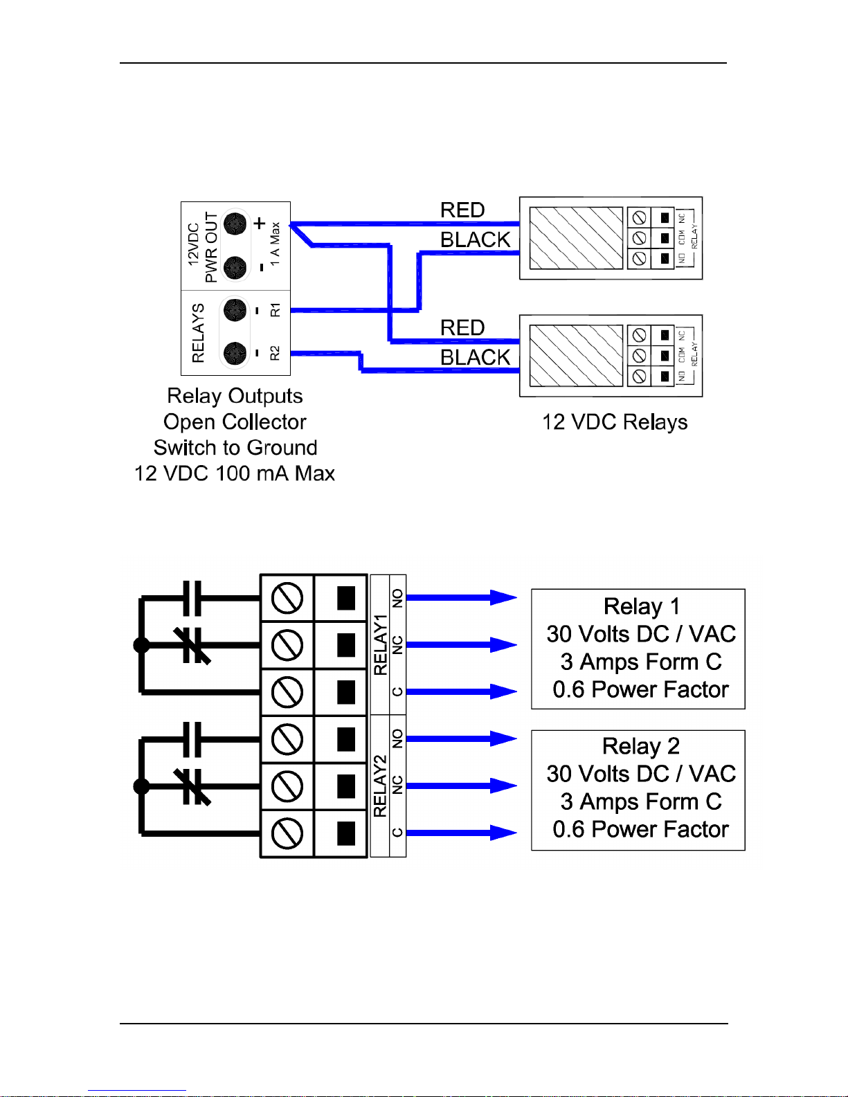
RELAY1 and RELAY2. These relays are rated at 3 Amps, 30 VAC/VDC, 0.6 power
factor.
Relay Controlled Outputs for the KT-1
Relay Controlled Outputs for KT-1-PCB
Auxiliary Outputs
Connect auxiliary outputs to readers and local warning devices. Auxiliary outputs
are used for visual and audible signals. They can be activated according to input con-
©Copyright, 2016, all rights reserved
34
Page 35

ditions, events and local alarms. Visual feedback of access operation is by LED. Audible warning devices, such as T-REX or reader buzzer, signal door alarms.
Connecting the KT-1
Connecting the VC-485 or the USB-485 to the RS-485 Bus:
Connect the RS-485 cable to (COM1) X+, X-. Controllers are linked together through
their RS-485 terminals. The maximum communication loop length is 1.2 km (4,000
ft) using appropriate cabling. The RS-485 communication loop should be wired with
Ethernet Category 3 double twisted pair (unshielded) network cable or better. The
RS-485 loop can operate from 1200 to 115200 Bauds under normal conditions.
Intermittent communication problems or erratic operation may require network
speed drops to 9600 or 19200 Bauds. Varying the network speed does not noticeably change the operation speed of the system.
Note 1: Connecting several KT-1 at a single point is not recommended, neither are
splitters or spider web (star) networks.
Note 2: There is no end-of-line resistor to install on the RS-485 COM1 terminals on
the last KT-1 controller of a loop
Note3: Use of VC-485 was not evaluated by UL.
© Copyright, 2016, allrights reserved
35
Page 36
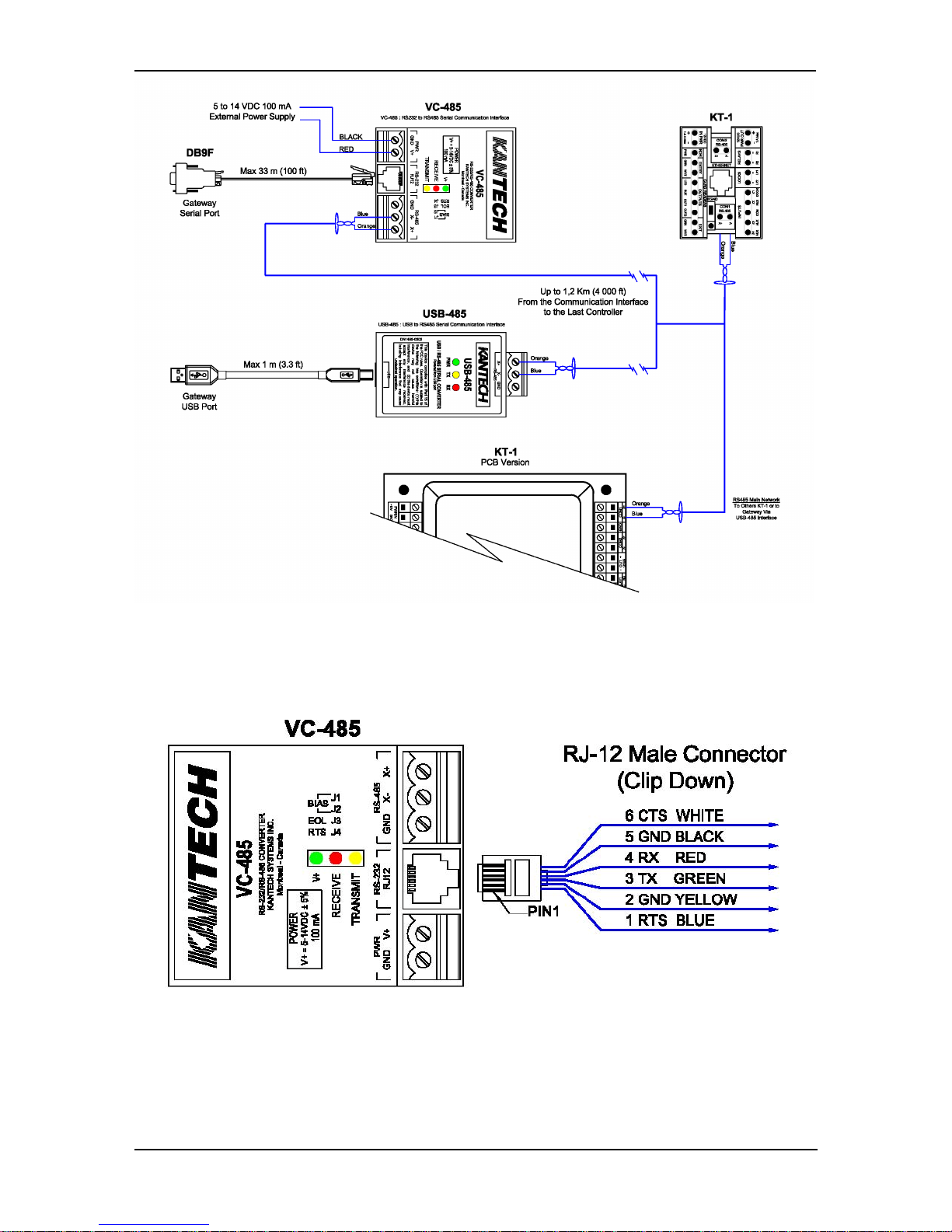
Note 4: If you must make up your own RS-232 cable with a RJ-12 connector, refer
to the following diagram for the RJ-12 pin-out:
©Copyright, 2016, all rights reserved
36
Page 37

Powering the KT-1
Powering the KT-1 is dependent upon the power selection options: PoE, PoE+ and
external power source. Both PoE and PoE+ are powered through the connection of
the Ethernet wire. However, it is also possible to power the KT-1 externally by connecting an external power supply to the 12 VDC input.
The power assembly needs to be finalized once the power is connected, but the
action is dependent upon the type of unit:
KT-1: Reattach the main boards into the wall-plate connector.
KT-1-PCB: For the PoE and PoE+, connect the ethernet wire to the RJ-45 connector
and put the main board back in place. If using an external power supply, reconnect
the 12 VDC connection.
The KT-1 can be installed in enclosure KT-1-CAB along with compatible power supply model KT-PS4085. When used in this configuration the KT-1 is also provided
with 4h of standby power. For KT-PS4085 use Plug in adapter PTC1640UG and battery rated 12V/7Ah.
Only apply power to the unit once all connections have been completed, tested
and the unit has been fixed to the wall.
Note: The KT-1 should not be connected to POE/PoE+ injector and external power
supply at the same time. Use PoE/PoE+ Phihong models POE125U-4-HP-R or
POE36U-1AT-R. AC trouble output from KT-PS4085 power supply shall be connected to one of the available inputs on KT-1 for transmission of AC loss event to
the monitoring console.
© Copyright, 2016, allrights reserved
37
Page 38
Reset & Configuration
One Button
The One Button is used in the configuration of the KT-1 controller. It is located on
the lower front of the KT-1, where the Kantech Shield is placed. Placing a finger
over the imprint of the shield activates various functionalities of the controller.
KT-1 Cover illustrating location of LEDs and Kantech Shield
There are three functionalities of the One Button, which are dependant upon how
long a finger is placed over the button:
1 - Status LED: Hold for 3 seconds to turn on the status LED for 10 minutes. Hold it
another 3 seconds to turn it off.
2 - Entrapass Enrollment: Hold for 6 seconds to trigger enrollment to EntraPass for
10 minutes and activate the status LED. Hold another 6 seconds to turn off
enrollment and status LED.
3 - Fifth Input: It can also be used as a fifth input, such as REX.
Note: There is a 20 second delay after replacing the cover before the One Button
will respond.
©Copyright, 2016, all rights reserved
38
Page 39
Reset Button
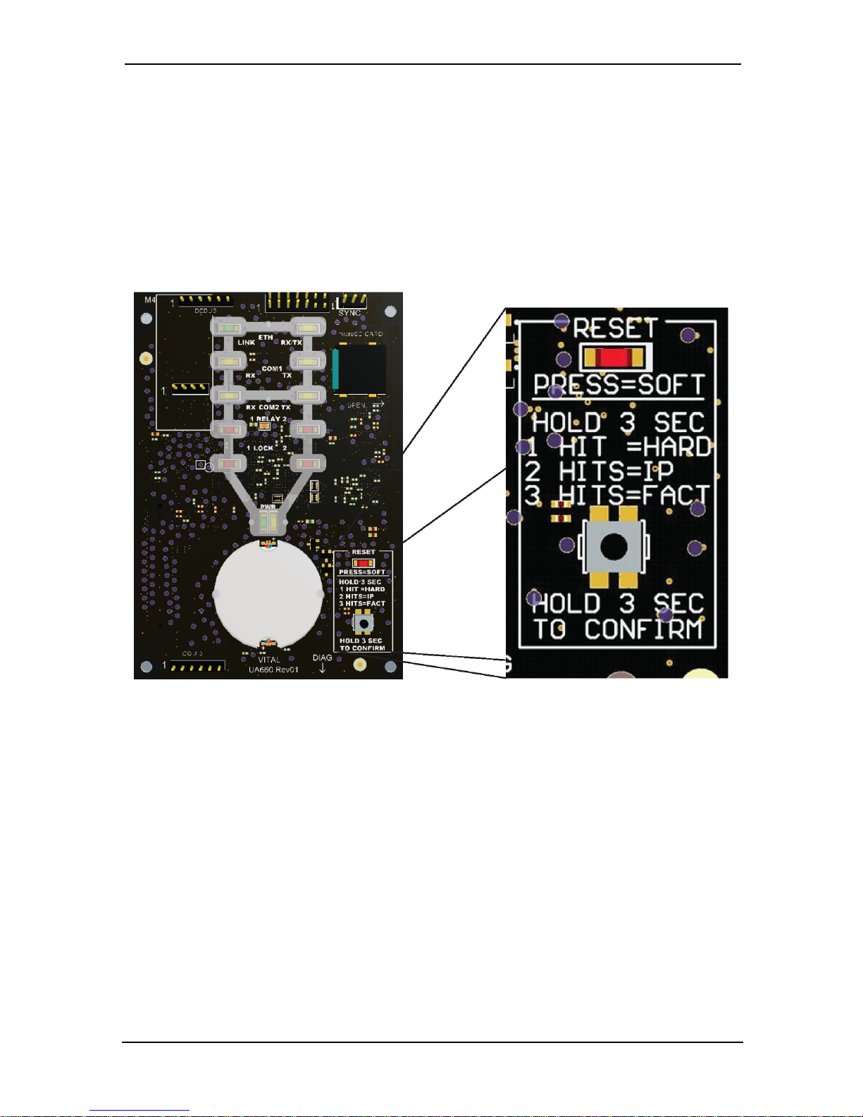
A reset of the system is possible using the reset button located on the main board.
The main board is accessed by removing the front cover of the KT-1. The reset button is on the bottom right side and is accompanied by a legend detailing the reset
options.
KT-1 with cover removed (L) and enlargement of reset button (R)
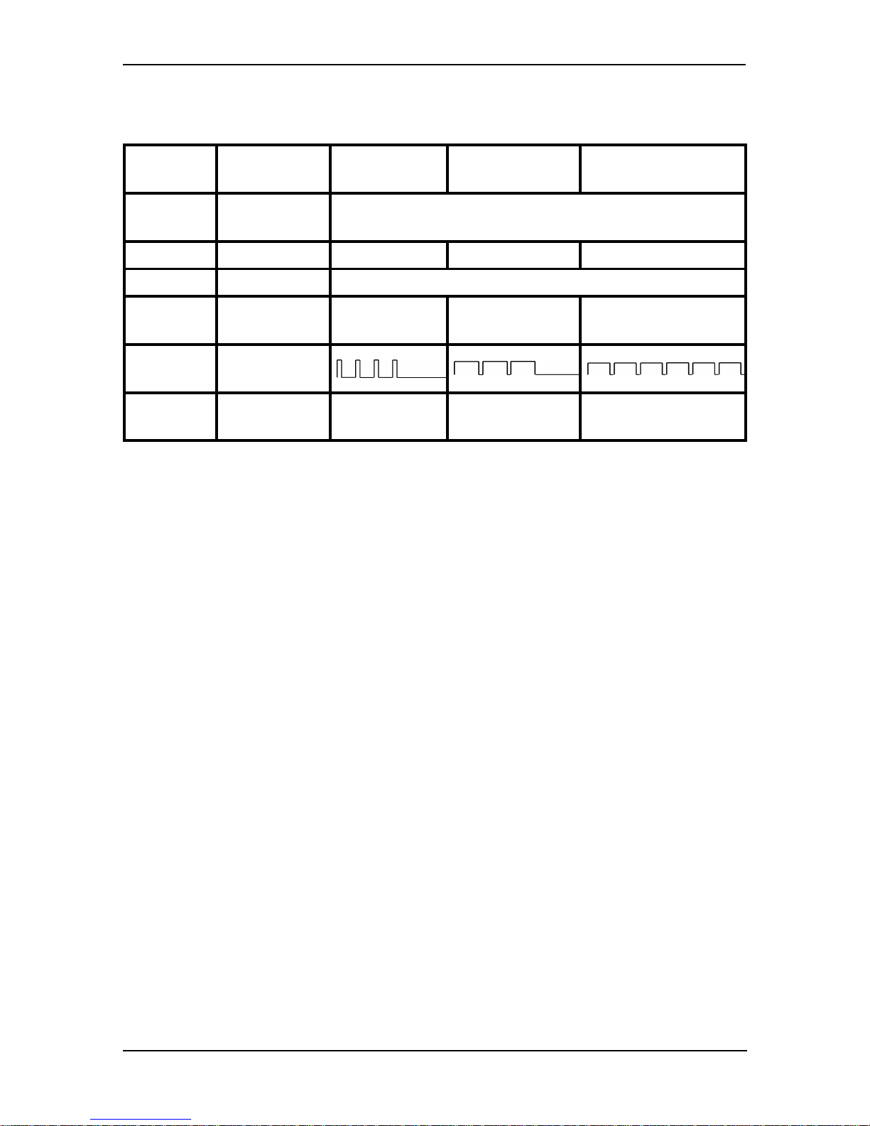
There are four reset options: Soft Reset, Hard Reset, Forced IP Reset and Factory
Default DHCP mode. The reset options are illustrated in the chart which follows.
© Copyright, 2016, allrights reserved
39
Page 40
Reset Chart
The following chart indicates reset types, with expanded descriptions below:
Soft Hard
Forced Default
Static
Factory Default DHCP
Initiation
Press and release
within 2 seconds
Hold 3 seconds until 5 beeps
Action - 1Hit 2 Hits 3 Hits
Confirmation - Hold 3 seconds until 5 beeps
LEDColor
See LED Patterns
Table
Red Yellow Yellow
Pattern
See LED Patterns
Table
Description
Continuous
Quick Flashing
4 Short Pulses 3 Long Pulses Continuous Long Pulses
Soft Reset:
• All controller memory definitions and parameters are verified and kept intact if
they are still valid. If not, the controller will go into Hard Reset mode.
• The internal event buffer is maintained if still valid.
• Previous IP address is kept, if defined.
• The flashing beat of the vital LED follows what it was before reset occurs, either
“Off Line communication state” (fast beat) or normal communication (1
beat/sec = Global or 3 beats/sec = Corporate).
• Controller generates the appropriate message: a) 'Power ON Soft Reset' b)
'Manual Pushbutton Soft Reset' c) 'Operator Soft Reset'.
Hard Reset
• All controller memory is set to default values.
• Internal event buffer is cleared.
• IP address is kept, if valid.
• The flashing beat of the vital LED is as Hard Reset state (4 beats/sec, if not in factory default or forced default static).
• Controller generates the message, 'Controller Hard Reset'.
• Internal RTC (Real Time Clock) and clock are settled to the default time and date
values January 1st 2014, 00:00:00, Wednesday.
©Copyright, 2016, all rights reserved
40
Page 41

Forced Default Static
• Same as 'Soft Reset' condition, except IP address is forced to the default static IP:
192.168.1.2 Subnet mask: 255.255.255.0.
The LED flashing pattern will remain on “Force default static” flashing beat (3
reversed pulses), until controller is reset to another mode.
Factory Default DHCP
• All controller's memory is settled to default values.
• Internal event buffer is cleared.
• Controller generates the message 'Controller Factory Default Reset'.
• The flashing beat of vital LED is “Reversed Flash” continuous beat.
• Internal RTC and clock are settled to the default time and date values January 1st
2014, 00:00:00, Wednesday.
Controller waits for valid communication from EntraPass to be received on any
effective comm port (ETH, RS-485) which will configure Controller Master Mode.
Power LED Status Indicator
There are two power LED status indicators, one green and one yellow. The colors
indicate when the primary power supply is present. The specific LED which illuminates is dependent upon the power source.
WARNING: DO NOT LOOK DIRECTLY AT LED WITH UNSHIELDED
EYES, OR DAMAGE TO RETINA MAY OCCUR.
Default Initialization
The KT-1 default initialization or Factory Default DHCP is done at Kantech. The following steps should be followed only if:
• You want to configure the KT-1 with the KT-Finder. (Refer to the section on configuring the KT-Finder, in this guide).
• The KT-1 was communicating via a VC-485 or a USB-485 interface and you want
to communicate via the ethernet port.
• You are using a KT-1 from another site and there is no communication.
© Copyright, 2016, allrights reserved
41
Page 42

Maintenance Recommendations
Important: Only qualified service technicians should perform maintenance recom-
mendations.
The KT-1 includes a lithium CR2032 primary battery. To avoid risk of explosion, the
battery must be replaced by a qualified service technician only. Do not crush, puncture, open, disassemble or otherwise mechanically interfere with the battery. Do
not try to recharge the battery. If you need to dispose of the PCB and/or the lithium
battery, wrap the KT-1 in non-conductive tape. Check with your local authorities for
battery disposal regulations.
Warning: Do not store the batteries in such a way that they come into contact with
each other or with any piece of metal. Explosion or fire may occur. Should fire
occur, use only dry chemical fire extinguishers. Do not use water to put out the fire.
Do not heat the batteries. Do not dispose of the batteries or PCB in a fire. Do not disassemble the batteries. Do not apply pressure to deform the batteries. Ensure that
the above precautions are strictly observed by related departments, including, but
not limited to, production, sales and outside contractors.
CAUTION: Risk of Fire, Explosion, And Burns. Do Not Recharge, Disassemble, Heat
Above 100°C Or Incinerate.
Configuring the KT-1 with the Web Configuration Page
This procedure is useful for configuring the KT-1 prior to going on site.
1 - Determine your connection to the KT-1 and choose the appropriate network
cable that you need.
2 - Make sure the KT-1 is in Forced Default Static mode before starting the con-
figuration. Verify the heartbeat patterns to determine the status. See the
Power LED Status Indicator table for details.
3 - Start your web browser and enter the following IP: 192.168.1.2 and press
Enter.
Note: The Web Configuration is for initial system set up only, and will no longer be
accessible once the system is configured.
©Copyright, 2016, all rights reserved
42
Page 43
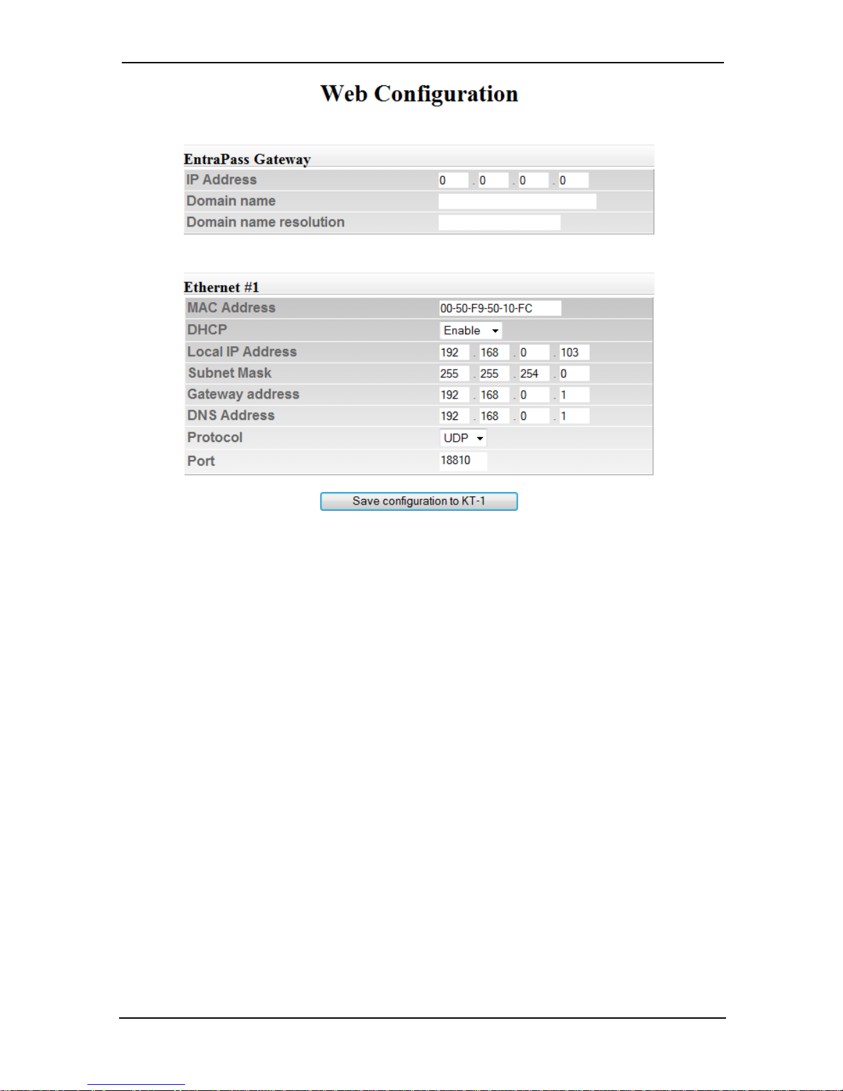
Note: Even though the KT-1 is in Forced Default Static mode, the DHCP status dis-
plays Enable. Make sure to change it accordingly when entering the parameters
from the Network Configuration Information Sheet.
4 - Enter the IP addresses. See the Entrapass Help Files for more information.
5 - Select a Protocol (TCP or UDP).
6 - Enter a Port (UDP only).
7 - Click on Save configuration to KT-1.
8 - When you go to the site with the configured KT-1, you will have to enter the
same details into the EntraPass workstation.
Configuring the KT-1 with the KT-Finder
The KT-Finder is an application used to configure the KT-1 over the local area network (LAN) or the wide area network (WAN). It doesn’t require any installation.
The KT-Finder application is:
• Located in: Start>All Programs>Entrapass Corporate Edititon>Server>KT-Finder
© Copyright, 2016, allrights reserved
43
Page 44
• Available as a free download from http://www.kantech.com
1 - Quit all EntraPass applications.
2 - Make sure the KT-1 is in Factory Default DHCP mode. See the Power LED Status
Indicator table for details.
3 - Start the KT-Finder.
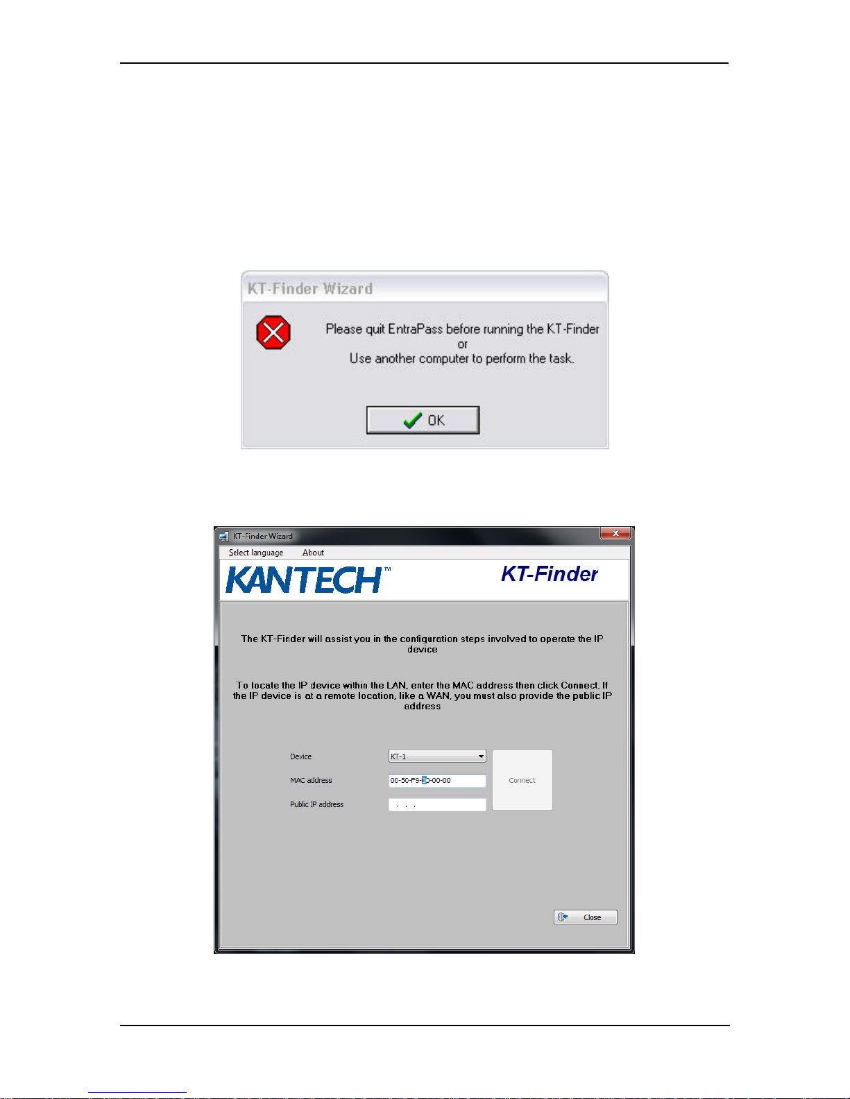
Note: If you try to run the KT-Finder while running EntraPass, you will get an error
message similar to this:
4 - Select KT-1 from the Device menu.
5 - Enter the MAC address of the KT-1 then click on Connect.
6 - When the KT-1 is found, the configuration page displays.
©Copyright, 2016, all rights reserved
44
Page 45
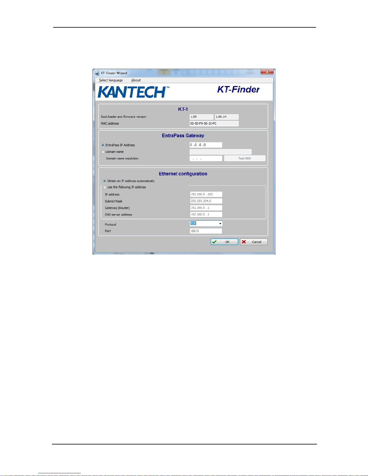
Configuring the KT-1 with the KT-Finder
7 - Enter the IP addresses. See the Entrapass Help Files for more information.
8 - Select a Protocol (UDP or TCP).
9 - Change the Port number, if required (not applicable in TCP).
Note: The port number should only be changed when you have more than one KT-
1 at the same remote site.
10 - Click OK.
11 - Repeat the procedure for each KT-1 at this site.
© Copyright, 2016, allrights reserved
45
Page 46
KT-1 Models, Expansion Kits & Related
Items
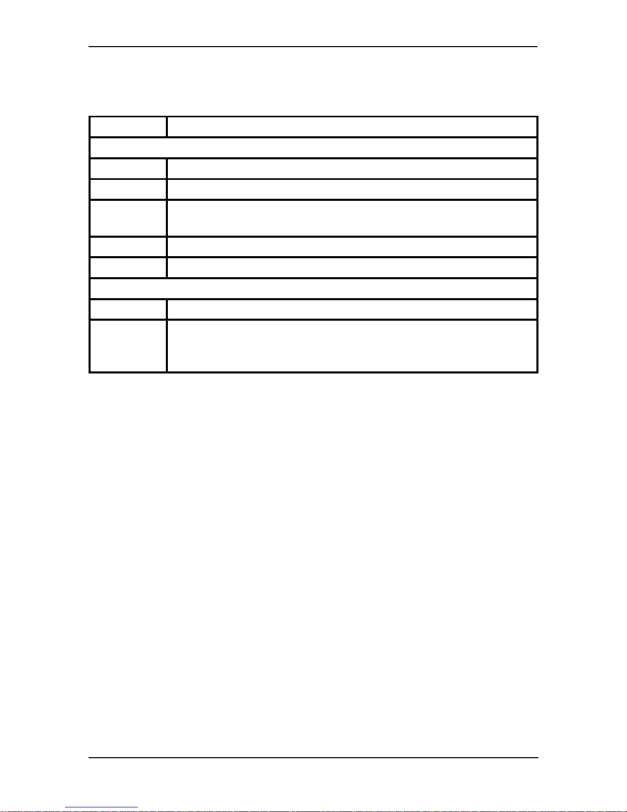
Part Number Description
KT-1 Models
KT-1 One-Door IP controller Single Gang Mount
KT-1-M One KT-1-PCB, IP controller PCB with metal cabinet (No P/S, No BAT)
KT-1-PCB
One-Door IP Controller PCB including connector board (Compatible with KT1-CAB-M or P)
KT-1-CVR Black replacement cover for KT-1 including back box
KT-1-CAB-M Metal enclosure only for KT-1-PCB
Miscellaneous Items
USB-485 USB-485 interface, USB cable 0.9 m (3 ft) and USB drivers on CD-ROM
VC-485
VC-485 interface, RS-232 cable 3 m (10 ft) with RJ-12 connectors, 7401012 (DB25F to RJ-12) adaptor, 740-1022 (DB9F to RJ-12) adaptor and
740-1033 (DB25M to RJ-12) adaptor
©Copyright, 2016, all rights reserved
46
Page 47

47
Compliance Specifications
UL
When KT-1 is enclosed in the metal cabinet model KT-1-CAB and powered by the power supply model
KTPS4085in conjunction with the external adapter PTC1640UG the following performance levels are
defined for the access control unit as per UL294:
Destructive attack: Level I (no attack test)
Line Security: Level II (Standard line security, RS-485or Ethernet) and Level III (encrypted line security
128 bit, Ethernet only)
Endurance: level IV (100,000 cycles)
Standby power: Level1 (when no standby power is provided)and level IV (4 hours, when using KTPS485)
Note: If KT-1 is used in a single gang configuration, powered by an external, separately listed power supply or PoE/PoE+ switch the performance levels remain the same with the exception of the standby time
that will be rated Level I (no secondary power source).
To comply with UL listings, the following requirements must be met:
• Installation locations and wiring methods shall be in accordance with the National Electrical Code,
ANSI/NFPA 70. Do not connect to a receptacle controlled by a switch.
• Use of a UL listed computer.
• Use of ULlisted readers (Wiegand 26 and 34bits, stripe 26 and 34bits, XSF 39 bits have been tested
and found to comply).
• Kantech XSF 39bits have been tested and found to comply.
• Use of a UL recognized tamper switch on every housing cabinet for the KT-1 One-Door Controller.
• Do not use the SmartLink option.
• Do not use a 230 VAC transformer (not UL listed).
• Use only UL listed cables.
• Use only UL listed adaptors.
• Use only a ULlisted power supply such as Kantech part number KT-PS4085(availablethrough
Kantech distributors or dealers, pleaserefer to the Technical Support contact information at the
beginning of this guide to obtain the specific transformer).
• The KT-1-EU has not been validated as a UL Listed system.
• The PTC1640UG and 12V/7Ah battery are used for 4 hours of standby power.
Note: Allcircuits are power limited with the exception of battery connection. Separation of 3/4" shall be
maintained between power limited and non-power limited wiring.
Note: Replace Battery with Pansonic or Energizer Part No. CR2032 Only. Use of another battery may
present a risk of fire or explosion.
UL 294 Compliance Notice
• Use only UL 294 or UL1076 listed power supply.
• Connect Kantech part number KT-ACPW-LED status indicator to the AC terminals of the KT-PS4085.
• Use Kantech part number KT-BATT-12 battery.
Note: Using a 12V/7Ah battery, backup battery provides a minimum of 4 hours stanby time.
© Copyright, 2016, allrights reserved
Page 48

UL 1076 Compliance Notice
• The KT-1 is UL1076 Listed as a Commercial Proprietary Control Unit Accessory and Proprietary Burglar Alarm Unit (Section 83.2), with EntraPass and Redundant Server, alarm system features, KT-300,
KT-400 Controllers, Kantech ioProx Proximity readers, and TRex request to exit devices – other
sensor devices (temperature, water level, etc.) may be used as long as they are also UL 1076 Listed.
• The EntraPass and Redundant Server shall be running at all time, and manned 24 hours a day, 365
days a year – The EntraPass and Redundant Server will each have their own operator workstation.
• Data processing equipment and office appliance and business equipment used as central supervisory
equipment station shall be listed to Information Technology Equipment - Safety-Part 1: General
Requirements - UL 60950-1.
• Should the EntraPassand/or Redundant Server be replaced, a UL 60950-1 listed computer must be
used.
• The following recommended system requirements apply to the EntraPass Server, Redundant Server,
Video Vault, Card Gateway, SmartLink, and Workstation:
• Operating Systems: Windows® 2008/Windows 2012/Windows 7 Standard/Enterprise
Server Editions/Windows 8
• Processor: Dual Core
• 4 GB RAM
• Minimum freehard disk space: 20 GB
• Color depth: 24-bit (16 million colors), required for Video Integration only
• Screen resolution: 1024 x 768
• AGP or PCI Express 8X graphics card with 64 MB memory and DirectX 9.0 support
• Network Interface card: 10/100 Base-T network adaptor
Note: Actual requirements may vary based on your operating system and configuration.
• The Central Supervisory Equipment shall employ supply line transient protection complying with the
Standard for Transient Voltage Surge Suppressors, UL 1449, with a maximum marked rating of 330 V.
• The Central Supervisory Equipment shall employ signal line Transient protection complying with the
Standard for Protectors for Data Communications and Fire Alarm Circuits, UL 497B, with a maximum marked rating of 50 V.
• The Central Supervisory Equipment shall employ that communication circuits and network components connected to the telecommunications network shall be protected by secondary protectors for communication circuits. These protectors shall comply with the Standard for Secondary
Protectors for Communications Circuits, UL 497A. These protectors shallbe used only in the protected site of the telecommunications network.
• The Central Supervisory Equipment shall be installed in a temperature controlled environment. A
temperature controlled environment is defined as one that can be maintained between 14° - 10°C
(55° - 95°F) by HVAC system. Twenty-four hours on standby power shallbe provided for the HVAC
system. The standby power system for the HVAC system may be supplied by an engine driven generator alone. A standby battery is not required to be used.
• A marking to identify the application and signaling function of the product islocated on the inside of
the unit (inner door sticker).
• For certified commercial proprietary control unit accessory applications, the requirements of UL
1076, CommercialProprietary Control Unit Accessory also apply.
• The reader(s), that is(are)designated to arm or disarm the alarm system, must be within the secured
side of the customer premises.
©Copyright, 2016, all rights reserved
48
Page 49

• The following Kantech readers have been validated by UL for the UL 1076Standard: P225W26,
P225KPW26, P225XSF, P225KPXSF, P325W26, P325KPW26, P325XSF, P325KPXSF and P600.
• Allalarms shallbe reported and acknowledged in the following priority:
Note: To set these priorities, please adjust the Event Parameters, found in EntraPass System
• Fire alarm and industrial supervision where a risk of injury to persons, or damage or destruction of
property may be involved
• Hold-up or panic alarm
• Burglar alarm
• Watchman tour (Guard tour)
• Fire-alarm supervision
• Burglar-alarm supervision
• Industrialsupervision where a risk of injury to persons, or damage or destruction of property will
not be involved.
If multiplex system signalsare transmitted directly from the protected systems to the central supervising station and the loss of the channel prevents the receipt of signals from protective circuits beyond
the fault, the number of separate signals on a single channelshallbe limited to 1000.
Minimum 4 hours of stand-by power provided by a standby rechargeable battery, rated 12V, 7Ah. Loss
of AC signal is transmitted immediately to the centralstation. Required use of Reader's LED (flashing) as
acknowledgement signal indicator.
Use EntraPass and under Definition/Alarm System/Door enable the option "Supervised door when
armed" when using the Reader's flashing LED to indicate the acknowlegdment signal. POE/POE+ feature
is not permitted for UL 1076.
FCC & IC
Operation is subject to the following two conditions: (1) this device may not cause harmful interference,
and (2) this device must accept any interference received including interference that may cause
undesired operation.
• This classB digital apparatus meets allrequirements of the Canadian Interference Causing Equipment
Regulations CAN ICES-3 (B) / NMB-3 (B).
CE & RCM
• EN60950-1, EN50130-4:2011, EN61000-6-3. CE Compliance in accordance with applicable LVD and EMC
Directives.
• Australia/New Zealand: RCM Compliance.
© Copyright, 2016, allrights reserved
49
Page 50

 Loading...