

Kantech IoPass SA-500, IoPass SA-600 Installation Manual

WARNING: This manual contains information on limitations regarding product use
and function and information on the limitations as to liability of the manufacturer.
The entire manual should be carefully read.
IoPass™
Stand-Alone Door Controller
Installation Manual
DN1445-0303 / V.2.22

Warning! Please Read Carefully
Note to Installers
This warning contains vital information. As the only individual in contact with system users, it is your responsibility to bring each item in
this warning to the attention of the users of this system.
System Failures
This system has been carefully designed to be as effective as possible.
There are circumstances, however, involving fire, burglary, or other
types of emergencies where it may not provide protection. Any access
system of any type may be compromised deliberately or may fail to
operate as expected for a variety of reasons. Some but not all of these
reasons may be:
Inadequate Installation
An access system must be installed properly in order to provide adequate protection. Every installation should be evaluated by a qualified
professional to ensure that every access point is adequately controlled
to the building owner’s or facility management’s expectations. Electric
solenoid locks, magnetic locks and gate controllers should be secure
and operate as intended. All latches used with the system should have
adequate holding power (lbs of force) and latch cavity size for the door
weight type (glass, wood, steel) used. A reevaluation must be done
during and after construction activity. An evaluation by the fire and/or
postal carrier is recommended if this service is available. All authorized emergency personnel should be able to gain immediate access to
the premises when required.
Criminal Knowledge
This system contains security features which were known to be effective at the time of manufacture. It is possible for persons with criminal
intent to develop techniques which reduce the effectiveness of these
features. It is important that a security system be reviewed periodically
to ensure that its features remain effective and that it be updated or
replaced if it is found that it does not provide the protection expected.
Access by Intruders
Intruders may enter through an unprotected access point, circumvent a
sensing device, evade detection by moving through an area of insufficient coverage, disconnecting a device, immediately following a person through the controlled gate or door, or interfering with the proper
operation of the system.
Power Failure
Control units, intrusion detectors, smoke detectors and many other
security devices require an adequate power supply for proper operation. If a device operates from batteries, it is possible for the batteries to
fail. Even if the batteries have not failed, they must be charged, in good
condition and installed correctly. If a device operates only by AC
power, any interruption, however brief, will render that device inoperative while it does not have power. Power interruptions of any length are
often accompanied by voltage fluctuations which may damage electronic equipment such as a security system. After a power interruption
has occurred, immediately conduct a complete system test to ensure
that the system operates as intended.
System Users
A user may not be able to operate the system due to permanent or temporary physical disability, inability to reach the keypad, or unfamiliarity with the correct operation. It is important that all system users be
trained in the correct operation of the system and that they know how
to respond when prompted.
Warnin g Devices
Warning devices such as sirens, bells, horns, or strobes may not warn
people or waken someone sleeping if there is an intervening wall or
door. If warning devices are located on a different level of the premise,
then it is less likely that the occupants will be alerted or awakened.
Audible warning devices may be interfered with by other noise sources
such as stereos, radios, televisions, air conditioners or other appliances,
or passing traffic. Audible warning devices, however loud, may not be
heard by a hearing-impaired person.
Component Failure
Although every effort has been made to make this system as reliable as
possible, the system may fail to function as intended due to the failure
of a component.
Security and Insurance
Regardless of its capabilities, a system is not a substitute for property
or life insurance. A system also is not a substitute for property owners,
renters, or other occupants to act prudently to prevent or minimize the
harmful effects of an emergency situation.

Limited Warranty
Kantech Systems warrants the original purchaser that for a period of
twelve months from the date of purchase, the product shall be free of
defects in materials and workmanship under normal use. During the
warranty period, Kantech Systems shall, at its option, repair or replace
any defective product upon return of the product to its factory, at no
charge for labour and materials. Any replacement and/or repaired parts
are warranted for the remainder of the original warranty or ninety (90)
days, whichever is longer. The original owner must promptly notify
Kantech Systems in writing that there is defect in material or workmanship, such written notice to be received in all events prior to expiration of the warranty period.
International Warranty
The warranty for international customers is the same as for any customer within Canada and the United States, with the exception that
Kantech Systems shall not be responsible for any customs fees, taxes,
or VAT that may be due.
Warranty Procedure
To obtain service under this warranty, please return the item(s) in question to the point of purchase. All authorized distributors and dealers
have a warranty program. Anyone returning goods to Kantech Systems
must first obtain an authorization number. Kantech Systems will not
accept any shipment whatsoever for which prior authorization has not
been obtained.
Conditions to Void Warranty
This warranty applies only to defects in parts and workmanship relating to normal use. It does not cover:
damage incurred in shipping or handling;
damage caused by disaster such as fire, flood, wind,
earthquake or lightning;
damage due to causes beyond the control of Kantech Sys-
tems such as excessive voltage, mechanical shock or
water damage;
damage caused by unauthorized attachment, alterations,
modifications or foreign objects;
damage caused by peripherals (unless such peripherals
were supplied by Kantech Systems);
defects caused by failure to provide a suitable installation
environment for the products;
damage caused by use of the products for purposes other
than those for which it was designed;
damage from improper maintenance;
damage arising out of any other abuse, mishandling or
improper application of the products.
Kantech Systems’s liability for failure to repair the product under this
warranty after a reasonable number of attempts will be limited to a
replacement of the product, as the exclusive remedy for breach of warranty. Under no circumstances shall Kantech Systems be liable for any
special, incidental, or consequential damages based upon breach of
warranty, breach of contract, negligence, strict liability, or any other
legal theory. Such damages include, but are not limited to, loss of profits, loss of the product or any associated equipment, cost of capital, cost
of substitute or replacement equipment, facilities or services, down
time, purchaser’s time, the claims of third parties, including customers,
and injury to property.
Disclaimer of Warranties
This warranty contains the entire warranty and shall be in lieu of any
and all other warranties, whether expressed or implied (including all
implied warranties of merchantability or fitness for a particular purpose) And of all other obligations or liabilities on the part of Kantech
Systems neither assumes nor authorizes any other person purporting to
act on its behalf to modify or to change this warranty, nor to assume for
it any other warranty or liability concerning this product.
This disclaimer of warranties and limited warranty are governed by the
laws of the state of California, U.S.A.
WARNING: Kantech Systems recommends that the entire system
be completely tested on a regular basis. However, despite frequent
testing, and due to, but not limited to, criminal tampering or electrical disruption, it is possible for this product to fail to perform as
expected.
Out of Warranty Repairs
Kantech Systems will at its option repair or replace out-of-warranty
products which are returned to its factory according to the following
conditions. Anyone returning goods to Kantech Systems must first
obtain an authorization number. Kantech Systems will not accept any
shipment whatsoever for which prior authorization has not been
obtained.
Products which Kantech Systems determines to be repairable will be
repaired and returned. A set fee which Kantech Systems has predetermined and which may be revised from time to time, will be charged for
each unit repaired.
Products which Kantech Systems determines not to be repairable will
be replaced by the nearest equivalent product available at that time.
The current market price of the replacement product will be charged
for each replacement unit.


Table of Contents
Section 1 • Introduction to IoPass™ 7
1.1 Product Overview .........................................................7
1.2 About this Manual ........................................................7
1.2.1 - New in this Version ...........................................7
1.2.2 - Record Sheet and Worksheet ............................7
1.3 Features .........................................................................7
1.4 Specifications ................................................................8
Section 2 • Installing and W iring IoPass™ 9
2.1 Unpacking the IoPass Unit ...........................................9
2.2 Required Equipment .....................................................9
2.3 Selecting a Mounting Location .....................................9
2.4 Typical Mounting Diagram ..........................................9
2.5 Mounting the IoPass Unit .............................................9
2.6 Mounting the IoProx P100 Reader .............................10
2.7 Connecting the Door Locking Device ........................10
2.8 Connecting the T.Rex Exit Detector or Exit Button ...10
2.9 Connecting the Door Contact .....................................10
2.10 Connecting the Alarm Annunciator ............................10
2.11 Setting Relay 1 Functions ...........................................11
2.12 Connecting the Power .................................................11
General Wiring Diagram ......................................... 12
Section 3 • Programming IoPass™ - Introduction 13
3.1 IoPass Programming Mode .........................................13
3.2 IoPass Factory Defaults ..............................................13
Section 4 • Programming IoPass™ - Features 15
4.1 Access Mode Selection ...............................................15
4.2 System Passwords ......................................................15
4.3 Card Management .......................................................15
4.4 Relay-1 Functions .......................................................15
4.5 Alarm Relay Functions ...............................................15
4.6 Tamper Alarm Function .............................................15
4.7 Forced Entry Alarm Function .....................................15
4.8 Door Ajar Alarm Function ..........................................16
4.9 PIN Error Alarm Function ..........................................16
4.10 Beeper Key Tone Function .........................................16
4.11 Loop Type Selection ...................................................16
4.12 Strike Relay Activation Timer ....................................16
4.13 Reset to Factory Default .............................................16
4.14 Selecting the System Language ..................................16
Section 5 • Programming IoPass™-Step by Step 17
5.1 Selecting the System Language ..................................17
5.2 Selecting the Access Mode .........................................17
5.3 Managing Passwords ..................................................17
5.3.1 - Modifying the Master Password ......................17
5.3.2 - Modifying the Main Password ........................18
5.3.3 - Modifying the Auxiliary Password .................18
5.3.4 - Modifying the Guard Password .......................18
5.4 Adding & Deleting Cards ...........................................19
5.4.1 - Single Add/Single Deletion .............................19
5.4.2 - Batch Add/Batch Deletion ..............................19
5.4.3 - Adding & Deleting Auxiliary Cards ...............20
5.5 Viewing Cards ............................................................20
5.6 Verifying a Card Number ...........................................21
5.7 Guard Function Configuration (Relay-1) ...................21
5.7.1 - Enabling the Guard Function ..........................21
5.7.2 - Arming / Disarming Quick Reference ............21
5.7.3 - Viewing the Audit Trail ..................................22
5.8 Auxiliary Function Configuration (Relay-1) .............. 22
5.8.1 - Enabling the Auxiliary Function .....................22
5.9 Configuring the Duress Function (Relay-1) ...............23
5.9.1 - Enabling the Duress Function .........................23
5.9.2 - Setting the Duress Relay Timer ......................23
5.9.3 - Using the Duress Function ..............................23
5.10 Configuring the Tamper Alarm Function ...................23
5.10.1 - Enabling the Tamper Alarm Function ...........23
5.10.2 - Using the Tamper Alarm Function ................24
5.11 Configuring the Forced Entry Alarm ..........................24
5.11.1 - Enabling/Disabling the Force Entry Alarm
Function ..........................................................24
5.11.2 - Using the Force Entry Function ...................24
5.12 Configuring the Door Ajar Function ..........................24
5.12.1 - Enabling/Disabling the Door Ajar Function .24
5.12.2 - Activating the Alarm Relay on Door Ajar ....25
5.12.3 - Setting the Door Ajar Timer ..........................25
5.12.4 - Using the Door Ajar Function .......................25
5.13 PIN Error Function Configuration ..............................25
5.13.1 - Enabling the PIN Error Function ..................25
5.13.2 - Enabling Auto-Deletion on PIN Error ..........25
5.14 Beeper Key Tone Configuration .................................26
5.15 Loop Type Configuration ...........................................26
5.16 Alarm Relay Timer Configuration .............................26
5.17 Setting the Strike Relay Timer ...................................27
5.18 Resetting the IoPass Unit to Factory Defaults ............27
Quick Reference Programming Table ................... 28
Programming Worksheet ....................................... 29
Card Information Record Sheet ............................. 30
Using the IoPass™ System .................................... 31
v

vi

Section 1 • Introduction to IoPass™
Product Overview
1.1
The IoPass is a fully programmable stand-alone access
control system that allows entry using proximity
technology, keypad or both, for up to 5,000 users. Compact
and surface mount, the IoPass is programmed directly from
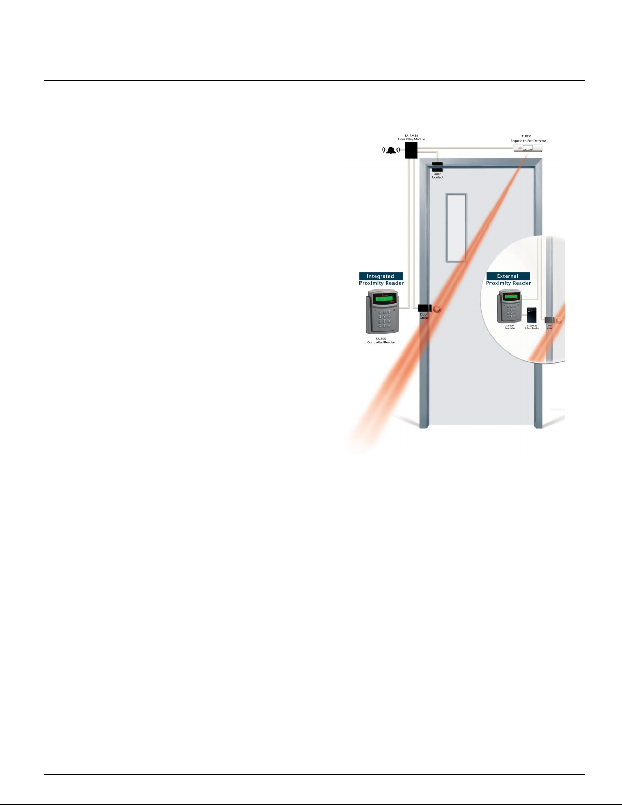
the keypad. The system is available in two models: with
integrated or external proximity reader.
Easy Programming
Programming is performed directly from the keypad with
visual confirmation of each operation on the 16-character,
2-line LCD display.
Custom Language
IoPass lets you select the system operating language.
Messages are displayed in English, French, Spanish,
German and Dutch.
Lockout on Invalid Password
To prevent unauthorized persons from gaining password
entry by trial and error, the system activates an alarm relay
and/or automatically deletes the card number after five
tries, once the option is selected in the system.
Integrated or External IoProx Proximity Reader
Two IoPass models are available. The integrated proximity
reader model is used for indoor installations. The external
proximity reader model provides a vandal and weather
resistant feature.
Higher Security Provided by Concealed Relay Module
The IoPass relay module is separate from the unit and can
be concealed inside a wall or ceiling. The relay module
acts as a connecting module between the IoPass unit and
the system devices. Devices (door contact, strike, exit
button or detector, alarm annunciator, power, etc.) are
connected to this module.
About this Manual
1.2
This Installation Manual provides installation and
programming instructions for IoPass installers. Please read
this manual carefully before installing or programming the
IoPass unit.
1.2.1 - New in this Version
This version of the manual was released to support the new
revision of the IoPass firmware (as of version 2.22 The
new features include:
1. Reset
2. View
function: you can clear the IoPass memory and
reset it to factory default values.
function: you can view the next and previous
card (access and auxiliary card) programmed in the
system.
Introduction to IoPass™ - Product Overview
Custom language selection: the IoPass unit can be
3.
operated in five languages (English, French, Spanish,
German and Dutch).
4. More transaction in the Audit trail: 380 last
transactions (instead of 10).
User PIN required for arming/disarming the unit.
5.
1.2.2 - Record Sheet and Worksheet
You can find the Card Information Record Sheet on
page 30. Please photocopy this form as reference material
so you can keep a record of the cards that are programmed
in the IoPass unit.
You can also find a
the settings that were modified within the unit. For more
information, refer to the “ Quick Reference Programming
Table”, page 28.
Features
1.3
• Proximity type reader with a read range up to 10 cm
(4");
• Capacity to store up to 5,000 user records;
• Large 2-line LCD of 16 characters with back light
feature including power saver function: the backlight
will turn off if inactive for more than 3 minutes;
• Three (3) access mode options:
• Card only (default);
• Card and PIN;
• Card only OR main password.
• Relay 1 offers one of the three (3) following options:
• Ability to arm and disarm an external alarm system;
• Duress function;
• Auxiliary card function.
• Cards can be enrolled/deleted in batch mode;
• The “Alarm Relay” can be activated if:
• an incorrect password is entered five times
consecutively within four (4) minutes;
• the unit detects a forced entry;
• the front cover of the unit is removed (tamper alarm
function);
• the door is opened longer than pre-set time (door ajar
function).
• Last 380 Access Granted card numbers can be viewed
on-screen;
• Audible key tones;
• Strike, alarm and duress relay have a selectable
activation timer (1-255 seconds);
• Selectable door left open timer (1-255 seconds);
• Can be mounted on a standard flush mount electrical
box (vertical or horizontal positioning of the box
acceptable).
Programming Worksheet
to record
7

Introduction to IoPass™ - Specifications
Specifications
1.4
• Typical read range—Up to 10 cm (4")1;
•
Input voltage
—12VDC;
• Current DC maximum—300mA;
•
Display
•
Cards
—16 characters, 2 lines, LCD with backlight;
:
• Access cards—5000 cards
• Auxiliary cards—20 cards
•
Dimensions (H • W • D)
:
• cm—15 x 11 x 4.5
• in—5.9 x 4.3 x 1.8
•
Weight
—380g (13.5oz);
• Case material—Gray ABS (UL 94V-0);
•
LED indicator
•
Operating temperatures
—Bicolor (green/red);
—0°C to 50°C (32°F to
122°F);
• Operating humidity—5% to 95% (relative humidity
non-condensing);
•
Door contact input
•
Request-to-Exit input
•
Relay output
—NO or NC selectable;
—NO or NC selectable;
(Strike, Alarm and Relay-1 relay)—Form
C, NO and NC, 3A, 24VDC;
• Strike, Alarm and Relay-1 timer—1 to 255 sec.;
•
Door ajar timer
•
Audit trail
•
Compatible cards
—1 to 255 sec.;
—On unit, last 380 transactions;
—IoProx cards P10SHL, P20DYE
and P40KEY;
•
PIN length
•
Certifications
—4 digits;
—CE and FCC.
1. Reduced read range with keytag and Dye-Sub cards.
8
Installing and Wiring IoPass™ - Unpacking the IoPass Unit
Section 2 • Installing and Wiring IoPass™
Unpacking the IoPass Unit
2.1
Check that the following parts are in your IoPass package:
• One (1) IoPass unit (SA-500 or SA-600);
• One (1) relay module (SA-RM56 including connectors);
• One (1) hardware kit;
• Ten (10) proximity keytags (P40KEY);
• One (1) IoProx P100 proximity reader (with SA-600
model only).
NOTE: The SA-RM56 relay module comes with all the
necessary connectors to facilitate installation.
Required Equipment
2.2
• Power supply—12VDC, 1A (required);
• Cables (required):
•
Between IoPass and reader
2 twisted pairs, solid conductor #22AWG
UNSHIELDED
•
Between IoPass and relay module
2 twisted pairs, solid conductor, #22AWG
UNSHIELDED
•
Between relay module and power supply
1 pair, solid conductor #22AWG UNSHIELDED
Typical Mounting Diagram
2.4
NOTE: Maximum wiring distance between equipment—
150m (500’).
• Door contact (recommended);
• Locking device (required);
• Door alarm or annunciator (recommended);
• T.Rex Request-to-Exit detector (recommended).
Selecting a Mounting Location
2.3
Select a mounting location for the unit using the following
guidelines:
• Close to the door being supervised;
• Away from areas with a large amount of background
noise;
• It is recommended that you mount the unit so that the
LCD is visible to users when requesting access. The top
of the unit should not be higher than 45 to 50 inches
from the floor.
Mounting the IoPass Unit
2.5
Remove the front panel by squeezing the sides of the
1.
unit and sliding forward;
Use the provided paper-sticker template to mark the
2.
position of the holes on the wall;
Mount the base unit to the wall using four (4) screws
3.
(provided) to secure the unit to the wall;
Replace the cover by gently sliding it back on the
4.
unit;
The unit offers a tamper alarm protection in case
5.
someone tries to remove the cover. For more
information, please refer to “Configuring the Tamper
Alarm Function” (page 23).
9

Installing and Wiring IoPass™ - Mounting the IoProx P100 Reader
Mounting the IoProx P100 Reader
2.6
NOTE: For model SA-600 only.
To mount the IoProx proximity reader, please refer to
installation instructions provided with the reader.
NOTE: If the IoPass unit and P100 reader are not on the
same side of the door, you will not be able to use the “card
and PIN” mode since the keypad of the IoPass unit will not
be accessible to cardholders when a valid card is presented
to the P100 reader.
Wiring Diagram
Connecting the Door Locking Device
2.7
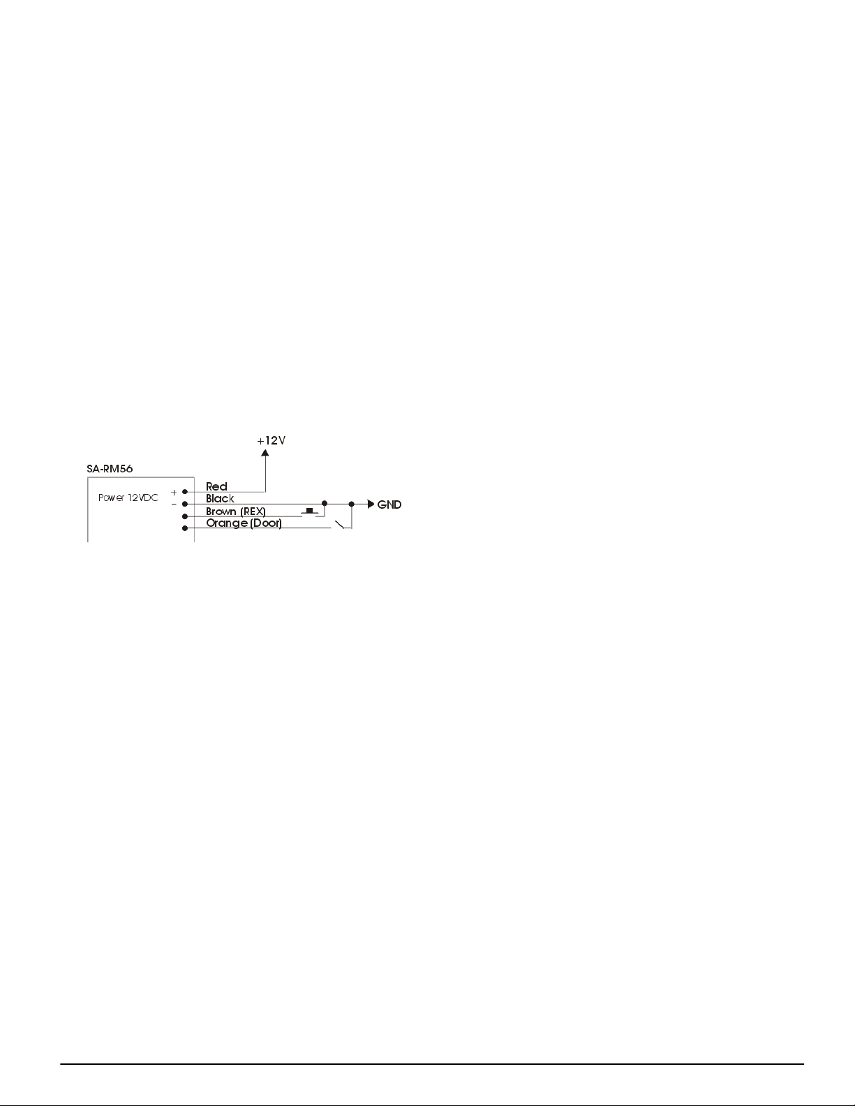
Connecting the T.Rex Exit Detector or Exit
2.8
Button
To install the T.Rex Exit Detector/push button, refer to the
manufacturer’s instructions. To connect it, refer to the
diagram below.
Wiring Diagram
Connecting the Door Contact
2.9
To install the door contact, refer to the manufacturer’s
instructions. To connect it, refer to the diagram below.
Wiring Diagram
To install the door locking device, refer to the
manufacturer’s instructions. To connect it, refer to the
diagram below.
Wiring Diagram
Connecting the Alarm Annunciator
2.10
To install the alarm annunciator, refer to the
manufacturer’s instructions. To connect the annunciator
(i.e.: horn, bell, etc.), refer to the diagram below.
Wiring Diagram
10
Setting Relay 1 Functions
2.11
Depending on how you intend to use Relay-1, you will
need to configure the jumpers, located on the SA-RM56
relay module, before you mount it inside the wall.
NOTE: For more information on the relay function, please
refer to “Relay-1 Functions” (page 15).
Jumper Settings:
Relay-1 Function
Function 1 2 3
DURESS
ON
OFF OFF
Installing and Wiring IoPass™ - Setting Relay 1 Functions
GUARD OFF
AUX. CARD OFF OFF
Connecting the Power
2.12
ON
OFF
ON
Once all other wiring is complete, power up the unit.
Wiring Diagram
NOTE: Once all connections are finished, you may start to
program the unit. Before you do so, we recommend you
read the section called “Programming IoPass™ Introduction” (page 13).
11
 Loading...